secondary metallurgy solutions - siemens industry, inc
TRANSCRIPT
Secondary metallurgy solutions Technology, mechanical engineering, automation, and electrical engineering from a single source – top values in productivity, consumption, and availability
siemens-vai.com
Answers for industry.
120430_Update_DS_Secondary_Metallurgy_Solutions_11RZ.indd 1 13.09.12 11:20
2
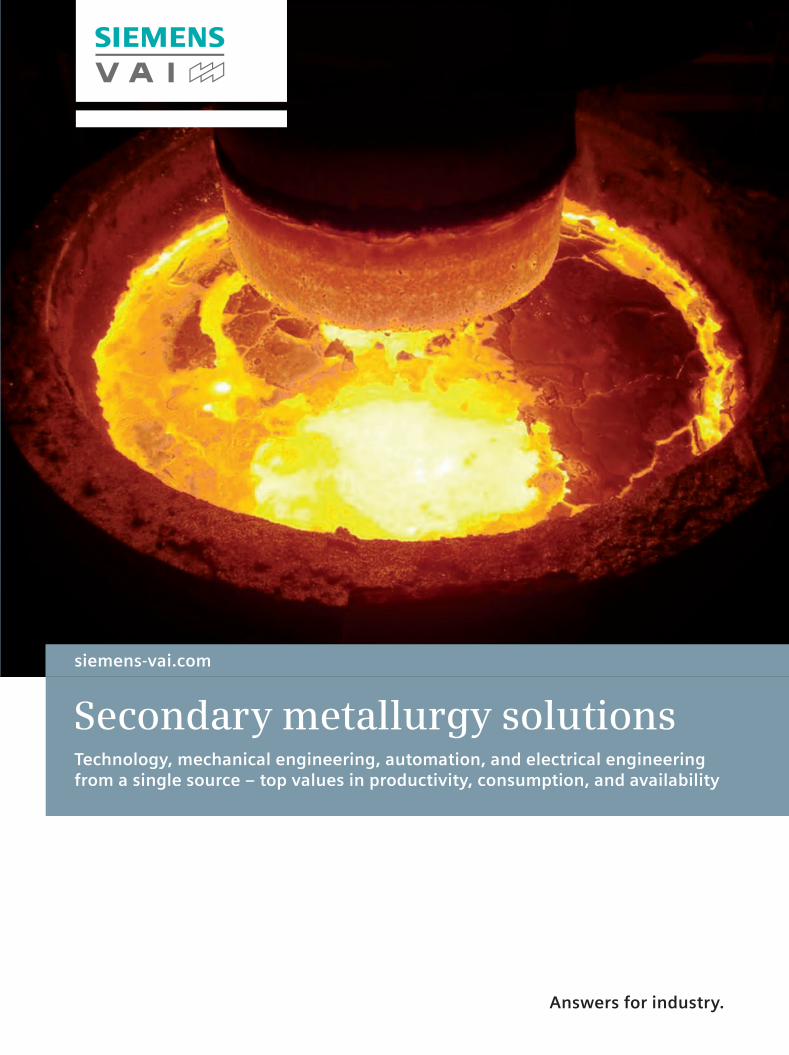
You expect:
• Efficient production and maximum pro-ductivity – through plant expertise
• Reliable delivery times, prompt commissioning, fast run-up – and reliable spare parts supply
• Flexible plant design – for the production of various steel qualities
• Low, demonstrably reachable consumption values – for alloying elements and energy
• Compliance with environmental regula-tions – including future requirements
As the demand for quality and stainless steel is rising throughout the industry and as the value added by secondary metallurgy treated steel increases, the number of installed and contracted secondary metallurgy plants for the improvement of the steel quality is growing.
2
120430_Update_DS_Secondary_Metallurgy_Solutions_11RZ.indd 2 13.09.12 11:20
3
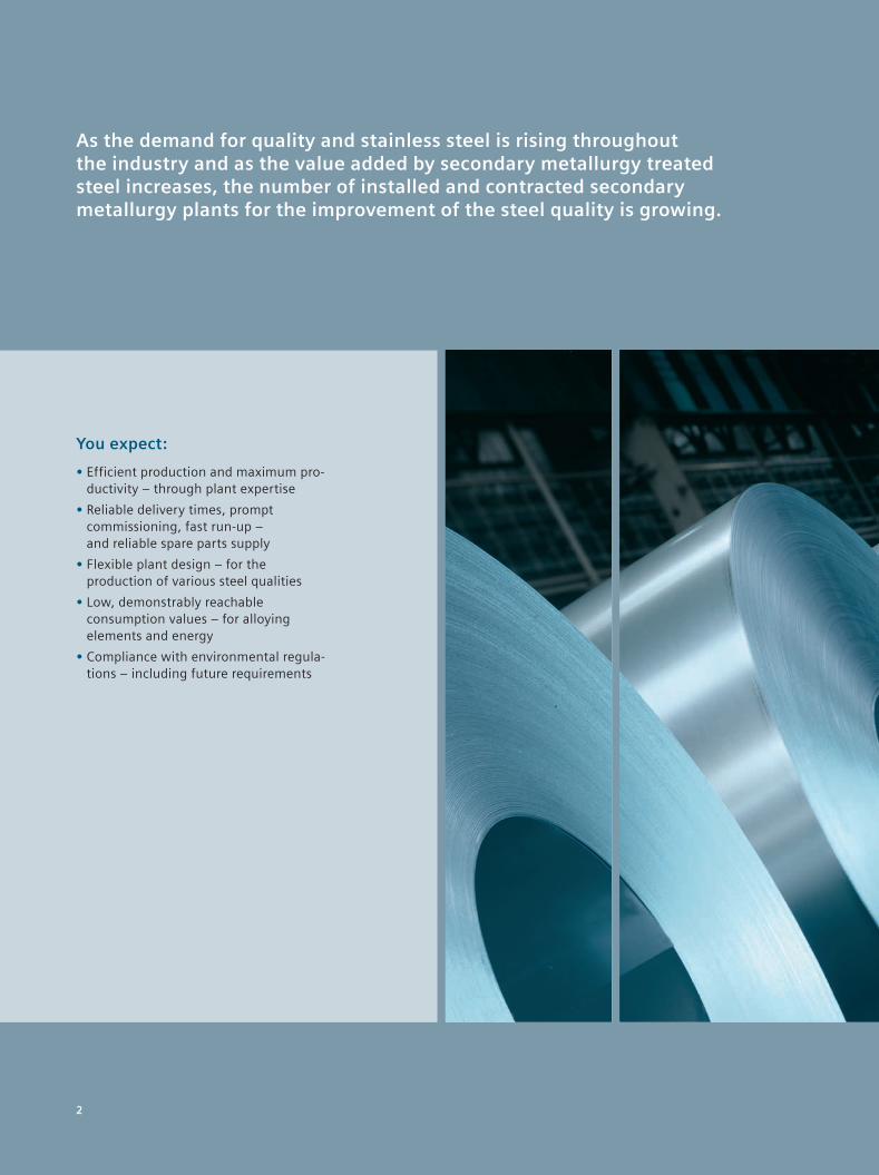
Your challenge:Rising demand for quality and stainless steel
Perfect teamwork for maximum efficiency It is vital that the entire plant should meet all required performance values, while at the same time delivering the planned steel quality in a safe, reproducible way. This requires basic expertise from your solution provider, as short charge cycle times, low consumption values, and reduced person-nel costs are decisive factors for the per-formance and productivity of your second-ary metallurgy.
Your customers require the best High availability, wide variety and the ability to adapt quickly to different requirements enable you to respond flexi-bly to new market requirements and the individual needs of your customers.
Long-lasting plant performance Siemens Metals Technologies can pass on its knowledge to your operating per-sonnel and support your service experts at any time with necessary spare parts.
Environmental requirements are growing International agreements and national laws require a reduction of pollution, dust, and CO2 emissions.
120430_Update_DS_Secondary_Metallurgy_Solutions_11RZ.indd 3 13.09.12 11:21
4
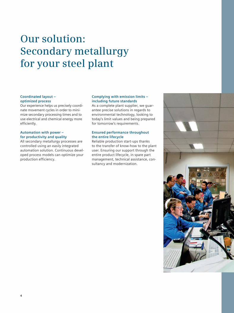
Our solution:Secondary metallurgy for your steel plant
Coordinated layout – optimized process Our experience helps us precisely coordi-nate movement cycles in order to mini-mize secondary processing times and to use electrical and chemical energy more efficiently.
Automation with power – for productivity and quality All secondary metallurgy processes are controlled using an easily integrated automation solution. Continuous devel-oped process models can optimize your production efficiency.
Complying with emission limits – including future standards As a complete plant supplier, we guar-antee precise solutions in regards to environmental technology, looking to today’s limit values and being prepared for tomorrow’s requirements.
Ensured performance throughout the entire lifecycle Reliable production start-ups thanks to the transfer of know-how to the plant user. Ensuring our support through the entire product lifecycle, in spare part management, technical assistance, con-sultancy and modernization.
120430_Update_DS_Secondary_Metallurgy_Solutions_11RZ.indd 4 13.09.12 11:21
5
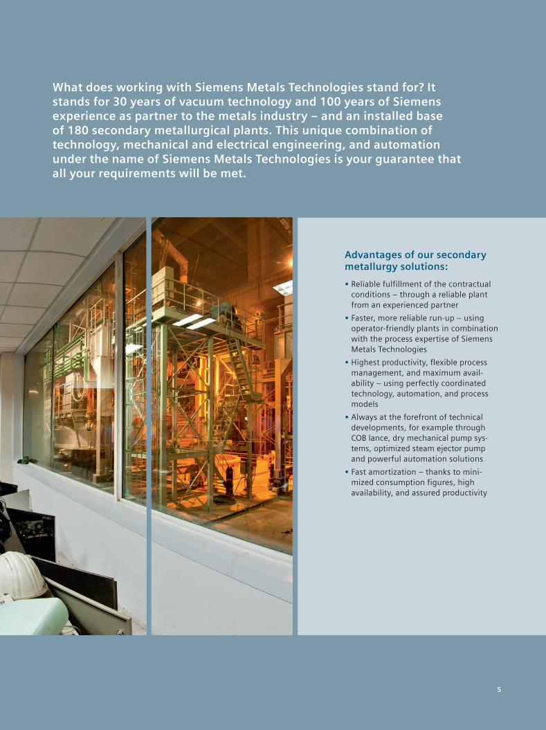
Advantages of our secondary metallurgy solutions:
• Reliable fulfillment of the contractual conditions – through a reliable plant from an experienced partner
• Faster, more reliable run-up – using operator-friendly plants in combination with the process expertise of Siemens Metals Technologies
• Highest productivity, flexible process management, and maximum avail-ability – using perfectly coordinated technology, automation, and process models
• Always at the forefront of technical developments, for example through COB lance, dry mechanical pump sys-tems, optimized steam ejector pump and powerful automation solutions
• Fast amortization – thanks to mini-mized consumption figures, high availability, and assured productivity
What does working with Siemens Metals Technologies stand for? It stands for 30 years of vacuum technology and 100 years of Siemens experience as partner to the metals industry – and an installed base of 180 secondary metallurgical plants. This unique combination of technology, mechanical and electrical engineering, and automation under the name of Siemens Metals Technologies is your guarantee that all your requirements will be met.
5
120430_Update_DS_Secondary_Metallurgy_Solutions_11RZ.indd 5 13.09.12 11:21
6
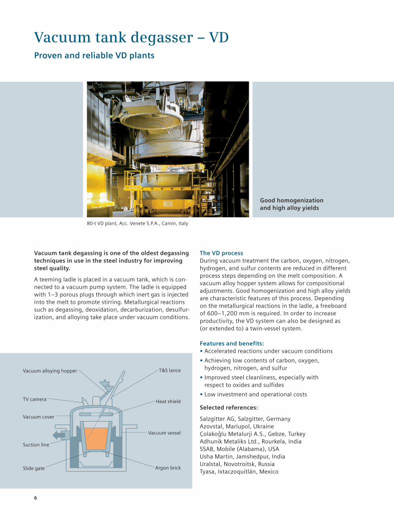
Vacuum tank degassing is one of the oldest degassing techniques in use in the steel industry for improving steel quality.
A teeming ladle is placed in a vacuum tank, which is con-nected to a vacuum pump system. The ladle is equipped with 1–3 porous plugs through which inert gas is injected into the melt to promote stirring. Metallurgical reactions such as degassing, deoxidation, decarburization, desulfur-ization, and alloying take place under vacuum conditions.
The VD process During vacuum treatment the carbon, oxygen, nitrogen, hydrogen, and sulfur contents are reduced in different process steps depending on the melt composi tion. A vacuum alloy hopper system allows for compositional adjustments. Good homogenization and high alloy yields are characteristic features of this process. Depending on the metal lurgical reactions in the ladle, a freeboard of 600–1,200 mm is required. In order to increase productivity, the VD system can also be designed as (or extended to) a twin-vessel system.
Features and benefits: • Accelerated reactions under vacuum conditions
• Achieving low contents of carbon, oxygen, hydrogen, nitrogen, and sulfur
• Improved steel cleanliness, especially with respect to oxides and sulfides
• Low investment and operational costs
Selected references:
Salzgitter AG, Salzgitter, GermanyAzovstal, Mariupol, UkraineÇolakoglu Metalurji A.S., Gebze, TurkeyAdhunik Metaliks Ltd., Rourkela, IndiaSSAB, Mobile (Alabama), USA Usha Martin, Jamshedpur, India Uralstal, Novotroitsk, Russia Tyasa, Ixtaczoquitlán, Mexico
Vacuum tank degasser – VDProven and reliable VD plants
80-t VD plant, Acc. Venete S.P.A., Camin, Italy
Good homogenization and high alloy yields
Vacuum alloying hopper
Vacuum cover
TV camera
Suction line
Slide gate
T&S lance
Heat shield
Vacuum vessel
Argon brick
120430_Update_DS_Secondary_Metallurgy_Solutions_11RZ.indd 6 13.09.12 11:21
7
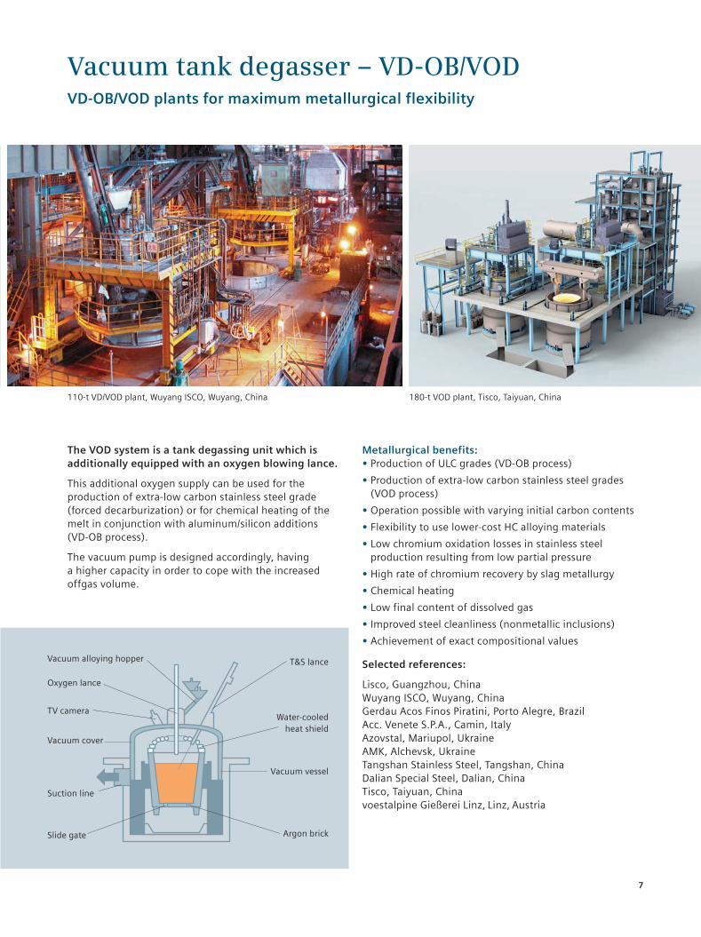
The VOD system is a tank degassing unit which is additionally equipped with an oxygen blowing lance.
This additional oxygen supply can be used for the produc tion of extra-low carbon stainless steel grade (forced decarburization) or for chemical heating of the melt in conjunction with aluminum/silicon additions (VD-OB process).
The vacuum pump is designed accordingly, having a higher capacity in order to cope with the increased offgas volume.
Metallurgical benefits: • Production of ULC grades (VD-OB process)
• Production of extra-low carbon stainless steel grades (VOD process)
• Operation possible with varying initial carbon contents
• Flexibility to use lower-cost HC alloying materials
• Low chromium oxidation losses in stainless steel production resulting from low partial pressure
• High rate of chromium recovery by slag metallurgy
• Chemical heating
• Low final content of dissolved gas
• Improved steel cleanliness (nonmetallic inclusions)
• Achievement of exact compositional values
Selected references:
Lisco, Guangzhou, ChinaWuyang ISCO, Wuyang, ChinaGerdau Acos Finos Piratini, Porto Alegre, BrazilAcc. Venete S.P.A., Camin, ItalyAzovstal, Mariupol, UkraineAMK, Alchevsk, UkraineTangshan Stainless Steel, Tangshan, ChinaDalian Special Steel, Dalian, ChinaTisco, Taiyuan, China voestalpine Gießerei Linz, Linz, Austria
Vacuum tank degasser – VD-OB/VODVD-OB/VOD plants for maximum metallurgical flexibility
110-t VD/VOD plant, Wuyang ISCO, Wuyang, China
Vacuum alloying hopper
Vacuum cover
TV camera
Suction line
Slide gate
T&S lance
Water-cooled heat shield
Vacuum vessel
Argon brick
Oxygen lance
180-t VOD plant, Tisco, Taiyuan, China
120430_Update_DS_Secondary_Metallurgy_Solutions_11RZ.indd 7 13.09.12 11:21
8
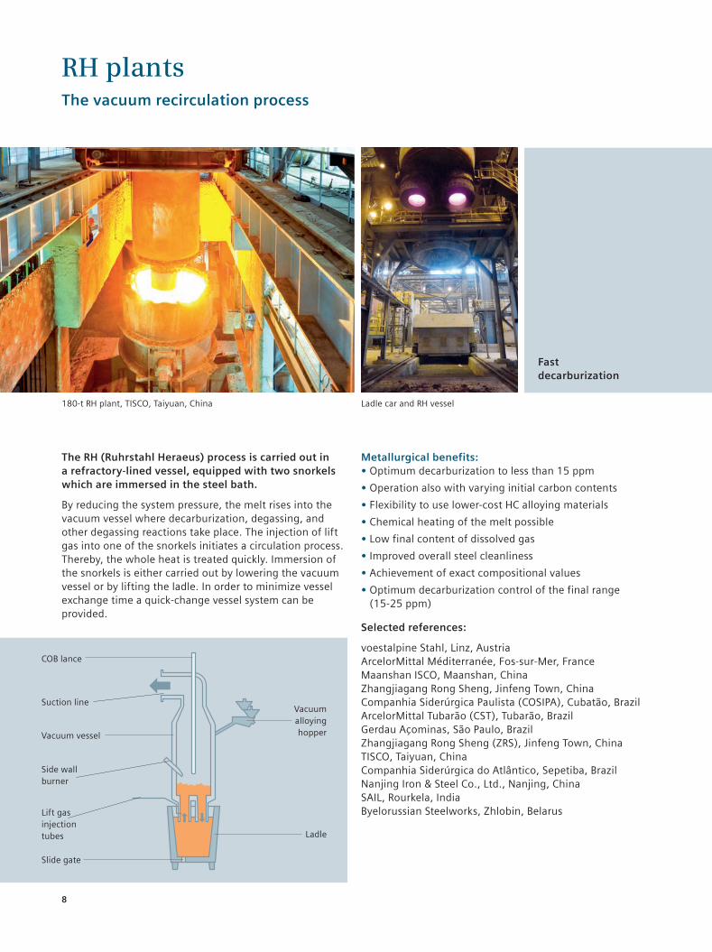
The RH (Ruhrstahl Heraeus) process is carried out in a refractory-lined vessel, equipped with two snorkels which are immersed in the steel bath.
By reducing the system pressure, the melt rises into the vacuum vessel where decarburization, degassing, and other degassing reactions take place. The injection of lift gas into one of the snorkels initiates a circulation process. Thereby, the whole heat is treated quickly. Immersion of the snorkels is either carried out by lowering the vacuum vessel or by lifting the ladle. In order to minimize vessel exchange time a quick-change vessel system can be provided.
Metallurgical benefits: • Optimum decarburization to less than 15 ppm
• Operation also with varying initial carbon contents
• Flexibility to use lower-cost HC alloying materials
• Chemical heating of the melt possible
• Low final content of dissolved gas
• Improved overall steel cleanliness
• Achievement of exact compositional values
• Optimum decarburization control of the final range (15-25 ppm)
Selected references:
voestalpine Stahl, Linz, AustriaArcelorMittal Méditerranée, Fos-sur-Mer, FranceMaanshan ISCO, Maanshan, ChinaZhangjiagang Rong Sheng, Jinfeng Town, ChinaCompanhia Siderúrgica Paulista (COSIPA), Cubatão, BrazilArcelorMittal Tubarão (CST), Tubarão, BrazilGerdau Açominas, São Paulo, BrazilZhangjiagang Rong Sheng (ZRS), Jinfeng Town, ChinaTISCO, Taiyuan, ChinaCompanhia Siderúrgica do Atlântico, Sepetiba, BrazilNanjing Iron & Steel Co., Ltd., Nanjing, ChinaSAIL, Rourkela, IndiaByelorussian Steelworks, Zhlobin, Belarus
RH plantsThe vacuum recirculation process
180-t RH plant, TISCO, Taiyuan, China Ladle car and RH vessel
Fast decarburization
Vacuum alloying hopper
Lift gas injection tubes
Vacuum vessel
Suction line
Slide gate
Ladle
Side wallburner
COB lance
120430_Update_DS_Secondary_Metallurgy_Solutions_11RZ.indd 8 13.09.12 11:21
9
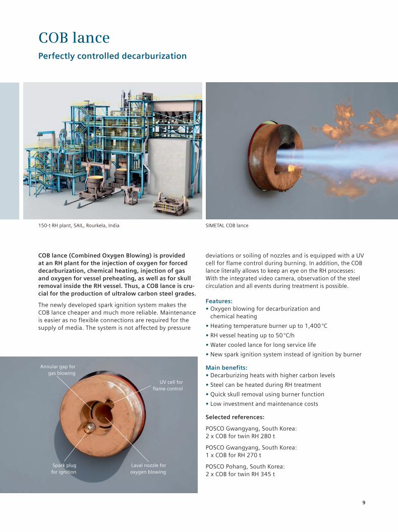
COB lance (Combined Oxygen Blowing) is provided at an RH plant for the injection of oxygen for forced decarburization, chemical heating, injection of gas and oxygen for vessel preheating, as well as for skull removal inside the RH vessel. Thus, a COB lance is cru-cial for the production of ultralow carbon steel grades.
The newly developed spark ignition system makes the COB lance cheaper and much more reliable. Maintenance is easier as no flexible connections are required for the supply of media. The system is not affected by pressure
deviations or soiling of nozzles and is equipped with a UV cell for flame control during burning. In addition, the COB lance literally allows to keep an eye on the RH processes: With the integrated video camera, observation of the steel circulation and all events during treatment is possible.
Features: • Oxygen blowing for decarburization and chemical heating
• Heating temperature burner up to 1,400 °C
• RH vessel heating up to 50 °C/h
• Water cooled lance for long service life
• New spark ignition system instead of ignition by burner
Main benefits: • Decarburizing heats with higher carbon levels
• Steel can be heated during RH treatment
• Quick skull removal using burner function
• Low investment and maintenance costs
Selected references:
POSCO Gwangyang, South Korea: 2 x COB for twin RH 280 t
POSCO Gwangyang, South Korea: 1 x COB for RH 270 t
POSCO Pohang, South Korea: 2 x COB for twin RH 345 t
COB lancePerfectly controlled decarburization
150-t RH plant, SAIL, Rourkela, India SIMETAL COB lance
UV cell for flame control
Laval nozzle for oxygen blowing
Annular gap for gas blowing
Spark plug for ignition
120430_Update_DS_Secondary_Metallurgy_Solutions_11RZ.indd 9 13.09.12 11:21
10
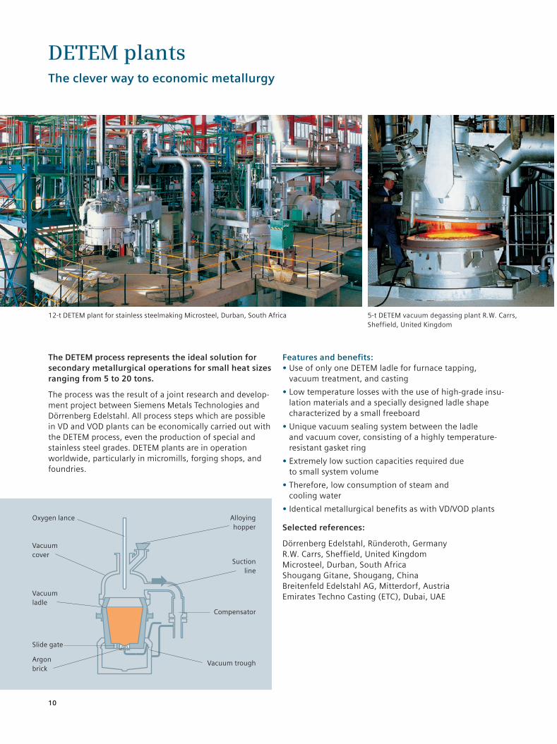
The DETEM process represents the ideal solution for secondary metallurgical operations for small heat sizes ranging from 5 to 20 tons.
The process was the result of a joint research and develop-ment project between Siemens Metals Technologies and Dörrenberg Edelstahl. All process steps which are possible in VD and VOD plants can be economically carried out with the DETEM process, even the production of special and stainless steel grades. DETEM plants are in operation worldwide, particularly in micromills, forging shops, and foundries.
Features and benefits: • Use of only one DETEM ladle for furnace tapping, vacuum treatment, and casting
• Low temperature losses with the use of high-grade insu-lation materials and a specially designed ladle shape characterized by a small freeboard
• Unique vacuum sealing system between the ladle and vacuum cover, consisting of a highly temperature-resistant gasket ring
• Extremely low suction capacities required due to small system volume
• Therefore, low consumption of steam and cooling water
• Identical metallurgical benefits as with VD/VOD plants
Selected references:
Dörrenberg Edelstahl, Ründeroth, GermanyR.W. Carrs, Sheffield, United KingdomMicrosteel, Durban, South AfricaShougang Gitane, Shougang, ChinaBreitenfeld Edelstahl AG, Mitterdorf, AustriaEmirates Techno Casting (ETC), Dubai, UAE
DETEM plantsThe clever way to economic metallurgy
5-t DETEM vacuum degassing plant R.W. Carrs, Sheffield, United Kingdom
12-t DETEM plant for stainless steelmaking Microsteel, Durban, South Africa
Alloying hopper
Argonbrick
Oxygen lance
Slide gate
Suctionline
Compensator
Vacuumcover
Vacuumladle
Vacuum trough
120430_Update_DS_Secondary_Metallurgy_Solutions_11RZ.indd 10 13.09.12 11:21
11
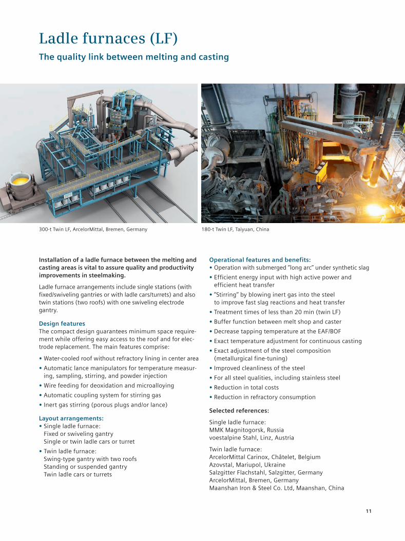
Installation of a ladle furnace between the melting and casting areas is vital to assure quality and productivity improvements in steelmaking.
Ladle furnace arrangements include single stations (with fixed/swiveling gantries or with ladle cars/turrets) and also twin stations (two roofs) with one swiveling electrode gantry.
Design features The compact design guarantees minimum space require-ment while offering easy access to the roof and for elec-trode replacement. The main features comprise:
• Water-cooled roof without refractory lining in center area
• Automatic lance manipulators for temperature measur-ing, sampling, stirring, and powder injection
• Wire feeding for deoxidation and microalloying
• Automatic coupling system for stirring gas
• Inert gas stirring (porous plugs and/or lance)
Layout arrangements: • Single ladle furnace: Fixed or swiveling gantry Single or twin ladle cars or turret
• Twin ladle furnace: Swing-type gantry with two roofs Standing or suspended gantry Twin ladle cars or turrets
Operational features and benefits: • Operation with submerged ‘’long arc’’ under synthetic slag
• Efficient energy input with high active power and efficient heat transfer
• ”Stirring’’ by blowing inert gas into the steel to improve fast slag reactions and heat transfer
• Treatment times of less than 20 min (twin LF)
• Buffer function between melt shop and caster
• Decrease tapping temperature at the EAF/BOF
• Exact temperature adjustment for continuous casting
• Exact adjustment of the steel composition (metallurgical fine-tuning)
• Improved cleanliness of the steel
• For all steel qualities, including stainless steel
• Reduction in total costs
• Reduction in refractory consumption
Selected references:
Single ladle furnace:MMK Magnitogorsk, Russiavoestalpine Stahl, Linz, Austria
Twin ladle furnace:ArcelorMittal Carinox, Châtelet, BelgiumAzovstal, Mariupol, UkraineSalzgitter Flachstahl, Salzgitter, GermanyArcelorMittal, Bremen, GermanyMaanshan Iron & Steel Co. Ltd, Maanshan, China
Ladle furnaces (LF)The quality link between melting and casting
180-t Twin LF, Taiyuan, China300-t Twin LF, ArcelorMittal, Bremen, Germany
120430_Update_DS_Secondary_Metallurgy_Solutions_11RZ.indd 11 13.09.12 11:21
12
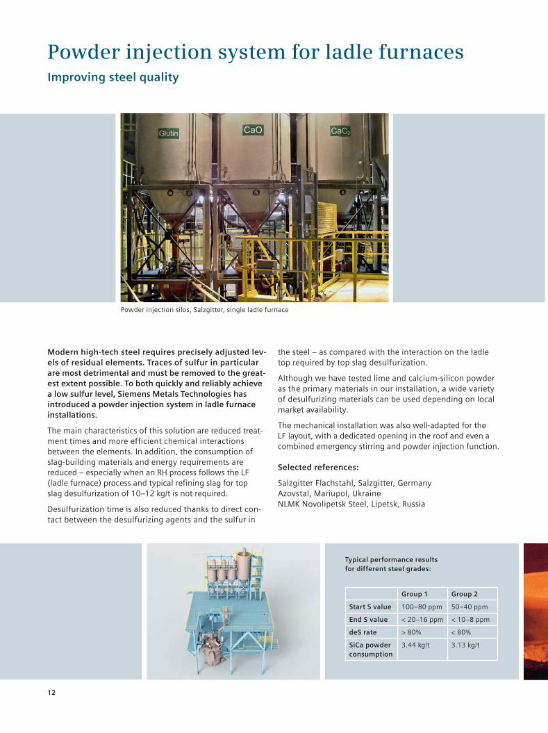
Modern high-tech steel requires precisely adjusted lev-els of residual elements. Traces of sulfur in particular are most detrimental and must be removed to the great-est extent possible. To both quickly and reliably achieve a low sulfur level, Siemens Metals Technologies has introduced a powder injection system in ladle furnace installations.
The main characteristics of this solution are reduced treat-ment times and more efficient chemical interactions between the elements. In addition, the consumption of slag-building materials and energy requirements are reduced – especially when an RH process follows the LF (ladle furnace) process and typical refining slag for top slag desulfurization of 10–12 kg/t is not required.
Desulfurization time is also reduced thanks to direct con-tact between the desulfurizing agents and the sulfur in
the steel – as compared with the in teraction on the ladle top required by top slag desulfurization.
Although we have tested lime and calcium-silicon powder as the primary materials in our installation, a wide variety of desulfurizing materials can be used depending on local market availability.
The mechanical installation was also well-adapted for the LF layout, with a dedicated opening in the roof and even a combined emergency stirring and powder injection function.
Selected references:
Salzgitter Flachstahl, Salzgitter, GermanyAzovstal, Mariupol, UkraineNLMK Novolipetsk Steel, Lipetsk, Russia
Powder injection system for ladle furnacesImproving steel quality
Powder injection silos, Salzgitter, single ladle furnace
Group 1 Group 2
Start S value 100–80 ppm 50–40 ppm
End S value < 20–16 ppm < 10–8 ppm
deS rate > 80% < 80%
SiCa powder consumption
3.44 kg/t 3.13 kg/t
Typical performance results for different steel grades:
120430_Update_DS_Secondary_Metallurgy_Solutions_11RZ.indd 12 13.09.12 11:21
13
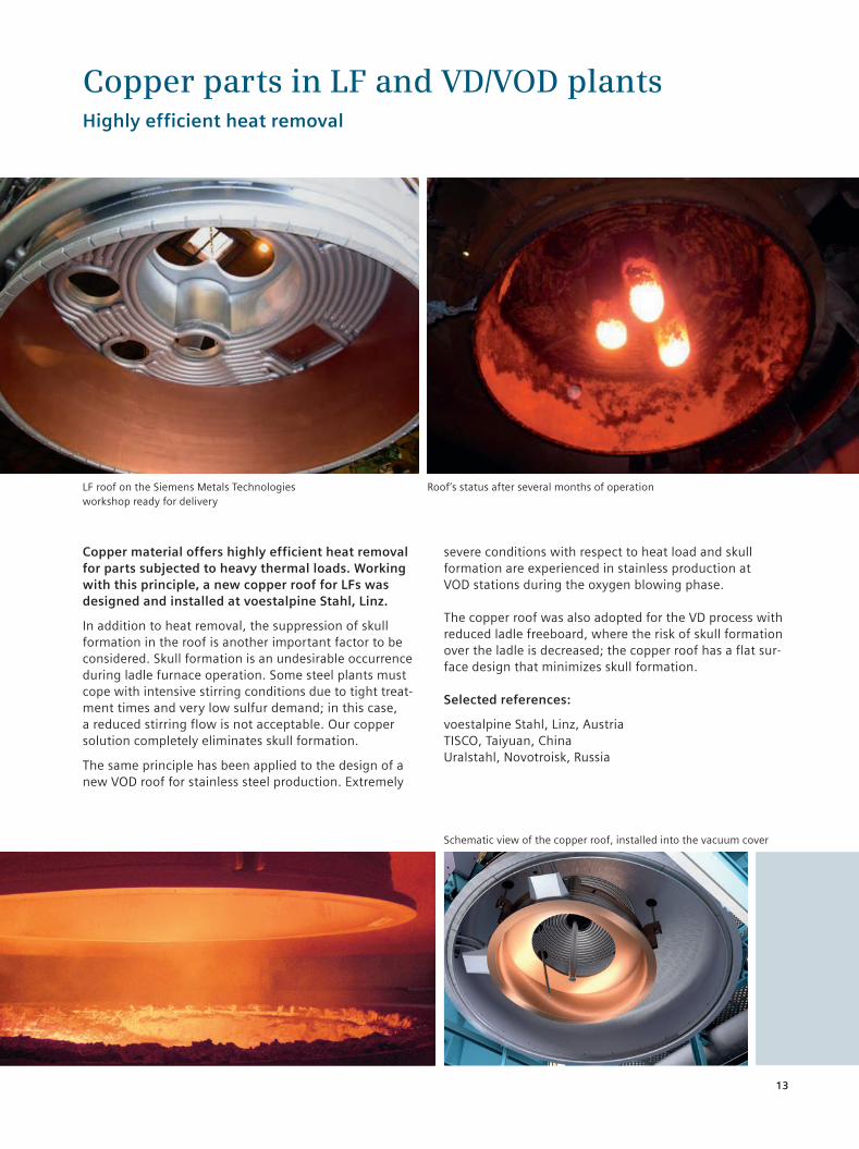
Copper material offers highly efficient heat removal for parts subjected to heavy thermal loads. Working with this principle, a new copper roof for LFs was designed and installed at voestalpine Stahl, Linz.
In addition to heat removal, the suppression of skull formation in the roof is another important factor to be considered. Skull formation is an undesirable occurrence during ladle furnace operation. Some steel plants must cope with intensive stirring conditions due to tight treat-ment times and very low sulfur demand; in this case, a reduced stirring flow is not acceptable. Our copper solution completely eliminates skull formation.
The same principle has been applied to the design of a new VOD roof for stainless steel production. Extremely
severe conditions with respect to heat load and skull formation are experienced in stainless production at VOD stations during the oxygen blowing phase.
The copper roof was also adopted for the VD process with reduced ladle freeboard, where the risk of skull formation over the ladle is decreased; the copper roof has a flat sur-face design that minimizes skull formation.
Selected references:
voestalpine Stahl, Linz, AustriaTISCO, Taiyuan, ChinaUralstahl, Novotroisk, Russia
Copper parts in LF and VD/VOD plantsHighly efficient heat removal
Roof’s status after several months of operation
Schematic view of the copper roof, installed into the vacuum cover
LF roof on the Siemens Metals Technologies workshop ready for delivery
120430_Update_DS_Secondary_Metallurgy_Solutions_11RZ.indd 13 13.09.12 11:22
14
The vacuum pump systems necessary for vacuum de- gassing units are entirely designed and engineered by Siemens Metals Technologies process specialists. This ensures that the technical performance of each supplied pump system will meet the process and metallurgical requirements under all climatic conditions.
A typical pump system consists of an arrangement of steam ejectors with the necessary condensation stages, often in combination with water ring pumps. Siemens Metals Technologies offers the full range of pumping systems, including customized and cost-saving solutions for tailpipe and hot-well tank systems. Dry mechanical pumps are also part of our portfolio.
An economic solution for dust removal Significant dust quantities (up to 5 kg of dust per ton of treated steel) are generated during vacuum degassing processes, mainly with oxygen blowing. In order to avoid the high investment costs which could be necessary for a water treatment plant, including a sludge thickener and sludge disposal system, a specially designed bag filter unit is installed in the suction line prior to the vacuum pump. Virtually all of the generated dust is removed from the waste gas stream under vacuum conditions.
Selected references:
POSCO Gwangyang, South Korea: 4-stage hybrid pump for twin RH plants from 270 to 345 t
TYASA, Ixtaczoquitlán, Mexico: Dry mechanical pump
voestalpine Gießerei Linz, Austria: Dry mechanical pump
Vacuum pump system and dust removalThe driving force behind every vacuum degassing plant
voestalpine Gießerei Linz, Linz, Austria
Cooling tower
Water ring pumps
Hybrid pump
Full steam ejector pump
Cooling tower
120430_Update_DS_Secondary_Metallurgy_Solutions_11RZ.indd 14 13.09.12 11:22