section 2 flight instruments - uppsala flygklubb integrated flight... · 190-00498-07 rev. a garmin...
TRANSCRIPT

190-00498-07 Rev. A Garmin G1000 Pilot’s Guide for Cessna Nav III 47
FLIGHT INSTRUMENTS
SYSTEMO
VERVIEWFLIG
HTIN
STRUMEN
TSEIS
AUDIO
PANEL
& CN
SFLIG
HTM
ANAG
EMEN
THAZARD
AVOIDAN
CEAFCS
ADD
ITION
ALFEATURES
APPEND
ICESIN
DEX
SECTION 2 FLIGHT INSTRUMENTS
WARNING: If the airspeed, attitude, altitude, or heading indications become unusable, refer to the backup instruments.
NOTE: The Automatic Flight Control System (AFCS) provides additional readouts and bugs on selected flight instruments. Refer to the AFCS Section for details on these bugs and readouts, as they appear on the display during certain AFCS modes.
Increased situational awareness is provided by replacing the traditional instruments on the panel with an easy-to-scan Primary Flight Display (PFD) that features a large horizon, airspeed, attitude, altitude, vertical speed, and course deviation information. In addition to the flight instruments, navigation, communication, terrain, traffic, and weather information are also presented on the PFD and explained in other sections of this Pilot’s Guide.
The following flight instruments and supplemental flight data are displayed on the PFD:
– Indicated airspeed
– True airspeed
– Trend vector
– Vspeed reference flags
– Trend vector
– Barometric setting
– Reference altitude
Indicators
– Turn Rate Indicator
– Bearing pointers and information windows
– Course Deviation Indicator (CDI)
– DME Information Window
– Generic timer
– Vspeed values
The PFD also displays various alerts and annunciations.

Garmin G1000 Pilot’s Guide for Cessna Nav III 190-00498-07 Rev. A48
FLIGHT INSTRUMENTS
SYST
EMO
VERV
IEW
FLIG
HTIN
STRU
MEN
TSEI
SAU
DIO
PAN
EL&
CN
SFL
IGHT
MAN
AGEM
ENT
HAZA
RDAV
OID
ANCE
AFCS
ADD
ITIO
NAL
FEAT
URES
APPE
ND
ICES
IND
EX
Figure 2-1 Primary Flight Display (Default)
1 NAV Frequency Box
2 Airspeed Indicator
3 True Airspeed
4 Current Heading
5 Turn Rate Indicator
6 Heading Bug
7 Outside Air Temperature (OAT)
8 Softkeys
9 System Time
10 Transponder Data Box
11 Horizontal Situation Indicator (HSI)
12 Barometric Altimeter Setting
13 Vertical Speed Indicator (VSI)
14 Reference Altitude Bug
15 Altimeter
16 Reference Altitude
17 COM Frequency Box
18 Navigation Status Box
19 Slip/Skid Indicator
20 Attitude Indicator
3
16
4
11
15
7
6
20
13
1819
12
17
8
9
2
1
10
5
14

190-00498-07 Rev. A Garmin G1000 Pilot’s Guide for Cessna Nav III 49
FLIGHT INSTRUMENTS
SYSTEMO
VERVIEWFLIG
HTIN
STRUMEN
TSEIS
AUDIO
PANEL
& CN
SFLIG
HTM
ANAG
EMEN
THAZARD
AVOIDAN
CEAFCS
ADD
ITION
ALFEATURES
APPEND
ICESIN
DEX
Figure 2-2 Additional PFD Information
1 Traffic Annunciation
2 Vspeed Reference
3 Selected Heading
4 Wind Data
5 Inset Map
6 DME Information Window
7 Bearing Information Windows
8 Minimum Descent Altitude/Decision Height
9 Flight Plan Window
10 Annunciation Window
11 Selected Course
12 Current Vertical Speed
13 Glideslope Indicator
14 Marker Beacon Annunciation
15 Terrain Annunciation
16 AFCS Status Annunciation
3
4
6
16
8
1
2
9
7
5
10
11
12
13
1415

Garmin G1000 Pilot’s Guide for Cessna Nav III 190-00498-07 Rev. A50
FLIGHT INSTRUMENTS
SYST
EMO
VERV
IEW
FLIG
HTIN
STRU
MEN
TSEI
SAU
DIO
PAN
EL&
CN
SFL
IGHT
MAN
AGEM
ENT
HAZA
RDAV
OID
ANCE
AFCS
ADD
ITIO
NAL
FEAT
URES
APPE
ND
ICES
IND
EX
2.1 FLIGHT INSTRUMENTS
AIRSPEED INDICATOR
NOTE: Refer to the Pilot’s Operating Handbook (POH) for airspeed criteria and Vspeed values.
The true airspeed is
indicated
(V ), at which point it turns red.
Figure 2-4 Red Pointer Showing Overspeed (Model 172R)
Figure 2-3 Airspeed Indicator (Model 182T)
Indicated Airspeed
Vspeed References
Speed Ranges
True Airspeed
Airspeed Trend Vector
denote flaps operating range, normal operating range, caution range, and never-exceed speed (Vis also present for low speed awareness.
the tip of the airspeed pointer while the other end moves continuously up or down corresponding to the rate of acceleration or deceleration. For any constant rate of acceleration or deceleration, the moving end of the line shows approximately what the indicated airspeed value will be in six seconds. If the trend vector crosses V , the text of the actual airspeed readout changes to yellow. The trend vector is absent if the speed remains constant or if any data needed to calculate airspeed is not available due to a system failure.

190-00498-07 Rev. A Garmin G1000 Pilot’s Guide for Cessna Nav III 51
FLIGHT INSTRUMENTS
SYSTEMO
VERVIEWFLIG
HTIN
STRUMEN
TSEIS
AUDIO
PANEL
& CN
SFLIG
HTM
ANAG
EMEN
THAZARD
AVOIDAN
CEAFCS
ADD
ITION
ALFEATURES
APPEND
ICESIN
DEX
Vspeeds (Glide, VR, VX, and VY,
Window. When active (on), the Vspeeds are displayed to the right of the airspeed scale.
Changing Vspeeds and turning Vspeed flags on/off:
1) Press the TMR/REF Softkey.
2) Turn the large FMS Knob to highlight the field of the desired Vspeed to be changed.
3) Use the FMS Knob to enter the desired value. When a speed has been changed from a default value, an asterisk appears next to the speed.
4) Press the ENT Key or turn the large FMS Knob to highlight the ON/OFF field.
5) Turn the small FMS Knob clockwise to ON or counterclockwise to OFF.
6) To remove the window, press the CLR Key or the TMR/REF Softkey.
Figure 2-5 Timer/References Window and Menu
Turning all Vspeed flags on/off:
1) Press the TMR/REF Softkey.
2) Press the MENU Key.
3) To activate all Vspeed flags, press the ENT Key with All References On highlighted.
4) To remove all Vspeed flags, turn the FMS Knob to highlight All References Off and press the ENT Key.
Restoring all Vspeed defaults:
1) Press the TMR/REF Softkey.
2) Press the MENU Key.
3) Turn the FMS Knob to highlight Restore Defaults and press the ENT Key.

Garmin G1000 Pilot’s Guide for Cessna Nav III 190-00498-07 Rev. A52
FLIGHT INSTRUMENTS
SYST
EMO
VERV
IEW
FLIG
HTIN
STRU
MEN
TSEI
SAU
DIO
PAN
EL&
CN
SFL
IGHT
MAN
AGEM
ENT
HAZA
RDAV
OID
ANCE
AFCS
ADD
ITIO
NAL
FEAT
URES
APPE
ND
ICES
IND
EX
ATTITUDE INDICATOR
1 Roll Pointer
2 Roll Scale
3 Horizon Line
4 Aircraft Symbol
5 Land Representation
6 Pitch Scale
7 Slip/Skid Indicator
8 Sky Representation
9 Roll Scale Zero
Figure 2-6 Attitude Indicator
5
6
8
72
4
3
1
9
of the pointer on the roll scale.
The displacement on a traditional inclinometer. The indicator bar moves with the roll pointer and moves laterally
indicated by the location of the bar relative to the pointer.
Figure 2-7 Slip/Skid Indication

190-00498-07 Rev. A Garmin G1000 Pilot’s Guide for Cessna Nav III 53
FLIGHT INSTRUMENTS
SYSTEMO
VERVIEWFLIG
HTIN
STRUMEN
TSEIS
AUDIO
PANEL
& CN
SFLIG
HTM
ANAG
EMEN
THAZARD
AVOIDAN
CEAFCS
ADD
ITION
ALFEATURES
APPEND
ICESIN
DEX
ALTIMETERThe
The
tape, the bug appears at the upper or lower edge of the tape. When the metric value is selected it is displayed
approximate altitude to be reached in six seconds at the current vertical speed. The trend vector is not shown if altitude remains constant or if data needed for calculation is not available due to a system failure.
Setting the Selected Altitude:
Turn the ALT Knob to set the Selected Altitude (large knob for 1000-ft increments, small knob for 100-ft increments).
If set, the Minimum Descent Altitude/Decision Height (MDA/DH) value is also available for the Selected Altitude.
Figure 2-8 Altimeter Settings, In Hg and Metric
Barometric Setting
Altitude Trend
Vector
Selected Altitude
Bug
Barometric Setting Box
(Hectopascals)
Barometric Minimums Bug
Selected Altitude
Indicated Altitude
Indicated Altitude (Meters)
Selected Altitude (Meters)
Selected Altitude
Bug
Displaying altitude in meters:
1) Press the PFD Softkey to display the second-level softkeys.
2) Press the ALT UNIT Softkey.
3) Press the METERS Softkey to turn on metric altitude readouts.
4) Press the BACK Softkey to return to the top-level softkeys.

Garmin G1000 Pilot’s Guide for Cessna Nav III 190-00498-07 Rev. A54
FLIGHT INSTRUMENTS
SYST
EMO
VERV
IEW
FLIG
HTIN
STRU
MEN
TSEI
SAU
DIO
PAN
EL&
CN
SFL
IGHT
MAN
AGEM
ENT
HAZA
RDAV
OID
ANCE
AFCS
ADD
ITIO
NAL
FEAT
URES
APPE
ND
ICES
IND
EX
The
Selecting the altimeter barometric pressure setting:
Turn the BARO Knob to select the desired setting.
Selecting standard barometric pressure:
1) Press the PFD Softkey to display the second-level softkeys..
2) Press the STD BARO Softkey; STD BARO is displayed in barometric setting box (Figure 2-9).
Figure 2-9 Standard Barometric Altimeter Setting
Changing altimeter barometric pressure setting units:
1) Press the PFD Softkey to display the second-level softkeys.
2) Press the ALT UNIT Softkey.
3) Press the IN Softkey to display the barometric pressure setting in inches of mercury (in Hg).
Or: Press the HPA Softkey to display the barometric pressure setting in hectopascals (hPa).
4) Press the BACK Softkey to return to the top-level softkeys.
through this altitude and the STD BARO
Setting the Baro Transition Alert:
1) Use the FMS Knob to select the AUX - System Setup Page.
2) Press the FMS Knob to activate the cursor.
3) Turn the large FMS Knob to highlight ‘OFF or ON’ in the ‘BARO TRANSITION ALERT’ box.
4) Turn the small FMS Knob to turn the alert OFF or ON and press the ENT Key.
5) With the altitude field highlighted, turn the small FMS Knob to select the desired altitude and press the ENT Key.
6) To cancel the selection, press the FMS Knob.

190-00498-07 Rev. A Garmin G1000 Pilot’s Guide for Cessna Nav III 55
FLIGHT INSTRUMENTS
SYSTEMO
VERVIEWFLIG
HTIN
STRUMEN
TSEIS
AUDIO
PANEL
& CN
SFLIG
HTM
ANAG
EMEN
THAZARD
AVOIDAN
CEAFCS
ADD
ITION
ALFEATURES
APPEND
ICESIN
DEX
Pressure setting flashes during climb above transition altitude if the STD BARO Softkey
has not been pressed.
Pressure setting flashes during descent below transition altitude to indicate setting has not
been changed from STD BARO.
Figure 2-10 Baro Transition Alert(AUX - System Setup Page)
VERTICAL SPEED INDICATOR (VSI)The
edge of the tape and the rate appears inside the pointer.

Garmin G1000 Pilot’s Guide for Cessna Nav III 190-00498-07 Rev. A56
FLIGHT INSTRUMENTS
SYST
EMO
VERV
IEW
FLIG
HTIN
STRU
MEN
TSEI
SAU
DIO
PAN
EL&
CN
SFL
IGHT
MAN
AGEM
ENT
HAZA
RDAV
OID
ANCE
AFCS
ADD
ITIO
NAL
FEAT
URES
APPE
ND
ICES
IND
EX
VERTICAL DEVIATION
NOTE: The Glidepath Indicator is only shown for aircraft with GIA 63W Integrated Avionics Units when SBAS is available.
The
source, the Glidepath Indicator appears as a magenta diamond during the approach. If the approach type
Full-scale deflection of two dots is 1000 feet.
Figure 2-11 Vertical Speed and Vertical Deviation Indications
Glipepath Indicator
Glidepath Indicator
Glideslope Indicator
Vertical Speed Indicator
Vertical Speed Pointer
VNV Target Altitude
Vertical Deviation Indicator
Vertical Speed and Deviation Indicator (VSI and VDI)
Glideslope Indicator
RequiredVertical Speed
Indicator

190-00498-07 Rev. A Garmin G1000 Pilot’s Guide for Cessna Nav III 57
FLIGHT INSTRUMENTS
SYSTEMO
VERVIEWFLIG
HTIN
STRUMEN
TSEIS
AUDIO
PANEL
& CN
SFLIG
HTM
ANAG
EMEN
THAZARD
AVOIDAN
CEAFCS
ADD
ITION
ALFEATURES
APPEND
ICESIN
DEX
HORIZONTAL SITUATION INDICATOR (HSI)The
Changing the HSI display format:
1) Press the PFD Softkey
2) Press the HSI FRMT Softkey.
3) Press the 360 HSI or ARC HSI Softkey.
Figure 2-12 Horizontal Situation Indicator (360˚ HSI)
1
10
11
14
12
16
3
4
2
8
97
5
1 Turn Rate Indicator
2 Selected Heading
3 Current Track Indicator
4 Lateral Deviation Scale
5 Navigation Source
6 Aircraft Symbol
7 Course Deviation Indicator (CDI)
8 Rotating Compass Card
9 OBS Mode Active
10 To/From Indicator
11 Heading Bug
12 Course Pointer
13 Flight Phase
14 Selected Course
15 Turn Rate and Heading Trend Vector
16 Current Heading
17 Lubber Line
6
13
17 15

Garmin G1000 Pilot’s Guide for Cessna Nav III 190-00498-07 Rev. A58
FLIGHT INSTRUMENTS
SYST
EMO
VERV
IEW
FLIG
HTIN
STRU
MEN
TSEI
SAU
DIO
PAN
EL&
CN
SFL
IGHT
MAN
AGEM
ENT
HAZA
RDAV
OID
ANCE
AFCS
ADD
ITIO
NAL
FEAT
URES
APPE
ND
ICES
IND
EX
Lateral Deviation
Scale
Course Deviation and To/From Indicator
Figure 2-13 Arc HSI
Course Pointer
Navigation Source
Flight Phase Annunciation
The heading bug on the compass rose corresponds to the selected heading.
Adjusting the selected heading:
Turn the HDG Knob to set the selected heading.
Press the HDG Knob to synchronize the bug to the current heading.
The
Adjusting the Selected Course:
Turn the CRS Knob to set the Selected Course.
Press the CRS Knob to re-center the CDI and return the course pointer to the bearing of the active waypoint or navigation station (see OBS Mode for adjusting a GPS course).
Selected Heading
Selected Course
Figure 2-14 Heading and Course Indications (Magnetic)
Current Heading Heading Bug

190-00498-07 Rev. A Garmin G1000 Pilot’s Guide for Cessna Nav III 59
FLIGHT INSTRUMENTS
SYSTEMO
VERVIEWFLIG
HTIN
STRUMEN
TSEIS
AUDIO
PANEL
& CN
SFLIG
HTM
ANAG
EMEN
THAZARD
AVOIDAN
CEAFCS
ADD
ITION
ALFEATURES
APPEND
ICESIN
DEX
true north has been loaded into the flight plan, the system generates a message to change the navigation angle setting to True at the appropriate time.
Figure 2-15 Heading and Course Indications (True)
Changing the navigation angle true/magnetic setting:
1) Use the FMS Knob to select the AUX - System Setup Page on the MFD.
2) Press the FMS Knob to activate the cursor.
3) Turn the large FMS Knob to highlight Nav Angle in the Display Units box.
4) Turn the small FMS Knob to highlight the desired setting and press the ENT Key.
TRUE - References angles to true north (T)
MAGNETIC - Angles corrected to the computed magnetic variation (Mag Var)
Figure 2-16 Navigation Angle Settings(AUX - System Setup Page)

Garmin G1000 Pilot’s Guide for Cessna Nav III 190-00498-07 Rev. A60
FLIGHT INSTRUMENTS
SYST
EMO
VERV
IEW
FLIG
HTIN
STRU
MEN
TSEI
SAU
DIO
PAN
EL&
CN
SFL
IGHT
MAN
AGEM
ENT
HAZA
RDAV
OID
ANCE
AFCS
ADD
ITIO
NAL
FEAT
URES
APPE
ND
ICES
IND
EX
TURN RATE INDICATORThe
Arrow Shown for Turn Rate> 4 deg/sec
Half-standard Turn Rate
Standard Turn Rate
Figure 2-17 Turn Rate Indicator and Trend Vector
BEARING POINTERS AND INFORMATION WINDOWSTwo
sources by pressing the PFD BRG or DME bearing pointers are light blue and are
the navigation source. The bearing pointers never override the CDI and are visually separated from the CDI by a white ring. Bearing pointers may be selected but not necessarily visible due to data unavailability. When
NOTE: ADF radio installation is optional.
Figure 2-18 HSI with Bearing and Distance Information
Bearing 1 Pointer
Bearing 2 Pointer
Bearing 2 Information Window
ADF Frequency
Pointer 2 Bearing SourceBearing 1 Information Window
Bearing Source Pointer 1
Distance to Bearing Source
Station Identifier
Frequency
Tuning Mode
Distance

190-00498-07 Rev. A Garmin G1000 Pilot’s Guide for Cessna Nav III 61
FLIGHT INSTRUMENTS
SYSTEMO
VERVIEWFLIG
HTIN
STRUMEN
TSEIS
AUDIO
PANEL
& CN
SFLIG
HTM
ANAG
EMEN
THAZARD
AVOIDAN
CEAFCS
ADD
ITION
ALFEATURES
APPEND
ICESIN
DEX
When a bearing pointer is displayed, the associated information window is also displayed. The Bearing
information:
line)bearing
source
selected.
Selecting bearing display and changing sources:
1) Press the PFD Softkey.
2) Press a BRG Softkey to display the desired bearing pointer and information window with a NAV source.
3) Press the BRG Softkey again to change the bearing source to GPS.
4) To remove the bearing pointer and information window, press the BRG Softkey again.
DME INFORMATION WINDOWThe
NOTE: DME installation is optional.
Displaying the DME Information Window:
1) Press the PFD Softkey.
2) Press the DME Softkey to display the DME Information Window.
3) To remove the DME Information Window, press the DME Softkey again.
Garmin G1000 Pilot’s Guide for Cessna Nav III 190-00498-07 Rev. A62
FLIGHT INSTRUMENTS
SYST
EMO
VERV
IEW
FLIG
HTIN
STRU
MEN
TSEI
SAU
DIO
PAN
EL&
CN
SFL
IGHT
MAN
AGEM
ENT
HAZA
RDAV
OID
ANCE
AFCS
ADD
ITIO
NAL
FEAT
URES
APPE
ND
ICES
IND
EX
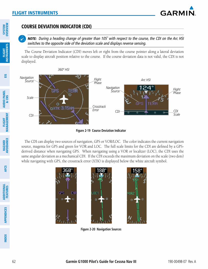
COURSE DEVIATION INDICATOR (CDI)
NOTE: During a heading change of greater than 105˚ with respect to the course, the CDI on the Arc HSI switches to the opposite side of the deviation scale and displays reverse sensing.
The Course Deviation Indicator (CDI) moves left or right from the course pointer along a lateral deviation scale to display aircraft position relative to the course. If the course deviation data is not valid, the CDI is not displayed.
Figure 2-19 Course Deviation Indicator
Crosstrack Error CDI
Navigation Source
CDI Scale
Flight Phase
Arc HSINavigation
Source
Scale
CDI
360º HSI
Flight Phase
navigation
same angular deviation as a mechanical CDI. If the CDI exceeds the maximum deviation on the scale (two dots)
Figure 2-20 Navigation Sources

190-00498-07 Rev. A Garmin G1000 Pilot’s Guide for Cessna Nav III 63
FLIGHT INSTRUMENTS
SYSTEMO
VERVIEWFLIG
HTIN
STRUMEN
TSEIS
AUDIO
PANEL
& CN
SFLIG
HTM
ANAG
EMEN
THAZARD
AVOIDAN
CEAFCS
ADD
ITION
ALFEATURES
APPEND
ICESIN
DEX
Changing navigation sources:
1) Press the CDI Softkey to change from GPS to VOR1 or LOC1. This places the light blue tuning box over the NAV1 standby frequency in the upper left corner of the PFD.
2) Press the CDI Softkey again to change from VOR1 or LOC1 to VOR2 or LOC2. This places the light blue tuning box over the NAV2 standby frequency.
3) Press the CDI Softkey a third time to return to GPS.
Pressing the CDI Softkey Cycles through
Navigation Sources
GPS Selected
Figure 2-21 Selecting a Navigation Source
LOC1 Selected
NAV1 Selected for Tuning
VOR2 Selected
NAV2 Selected for Tuning
when all of the following occur:
provided after the switch.

Garmin G1000 Pilot’s Guide for Cessna Nav III 190-00498-07 Rev. A64
FLIGHT INSTRUMENTS
SYST
EMO
VERV
IEW
FLIG
HTIN
STRU
MEN
TSEI
SAU
DIO
PAN
EL&
CN
SFL
IGHT
MAN
AGEM
ENT
HAZA
RDAV
OID
ANCE
AFCS
ADD
ITIO
NAL
FEAT
URES
APPE
ND
ICES
IND
EX
GPS CDI SCALING
magenta, but when cautionary conditions exist the color changes to yellow. If the current leg in the flight plan
scaling is smaller than the automatic setting for enroute and terminal phases, the CDI is scaled accordingly and the selected setting is displayed rather than the flight phase annunciation.
Changing the selected GPS CDI setting:
1) Use the FMS Knob to select the AUX - System Setup Page on the MFD.
2) Press the FMS Knob to activate the cursor.
3) Turn the large FMS Knob to highlight Selected in the GPS CDI box.
4) Turn the small FMS Knob to highlight the desired setting and press the ENT Key.
5) To cancel the selection, press the FMS Knob or the CLR Key.
Figure 2-22 GPS CDI Settings(AUX - System Setup Page)

190-00498-07 Rev. A Garmin G1000 Pilot’s Guide for Cessna Nav III 65
FLIGHT INSTRUMENTS
SYSTEMO
VERVIEWFLIG
HTIN
STRUMEN
TSEIS
AUDIO
PANEL
& CN
SFLIG
HTM
ANAG
EMEN
THAZARD
AVOIDAN
CEAFCS
ADD
ITION
ALFEATURES
APPEND
ICESIN
DEX
Figure 2-23 Automatic CDI Scaling2.
0 nm
Enroute(Oceanic if >200 nmfrom nearest airport)
0.3
nm
MissedApproach
1.0
nm
Approach
1.0
nm
Terminal1.
0 nm
Terminal
0.3
nm
Departure
CD
I Ful
l-sca
le D
efle
ctio
n
Refer to accompanyingapproach CDI scaling figures
departure
terminal CDI scaling (1.0 nm) under the following conditions:
- The next leg in the departure procedure is not aligned with the departure runway
Glossary for leg type definitions)
enroute phase of flight is automatically entered and CDI scaling
- When navigating with an active departure procedure, the flight phase and CDI scale does not change
the leg after the last departure waypoint has been activated or a direct-to waypoint is activated.
and the approach procedure has not yet commenced, the CDI is scaled for oceanic
terminal
over a distance of 1.0 nm.
approach
once the approach procedure is activated or if Vectors-To-Final (VTF) are selected.
final approach segment course.
- If the active waypoint is part of the missed approach procedure, the active leg and the preceding missed approach legs must be aligned with the final approach segment course and the aircraft must not have passed the turn initiation point.

Garmin G1000 Pilot’s Guide for Cessna Nav III 190-00498-07 Rev. A66
FLIGHT INSTRUMENTS
SYST
EMO
VERV
IEW
FLIG
HTIN
STRU
MEN
TSEI
SAU
DIO
PAN
EL&
CN
SFL
IGHT
MAN
AGEM
ENT
HAZA
RDAV
OID
ANCE
AFCS
ADD
ITIO
NAL
FEAT
URES
APPE
ND
ICES
IND
EX
Figure 2-24 Typical LNAV and LNAV+V Approach CDI Scaling
1.0
nm
2 nm
350
ftangle setby system
0.3
nm
FAF
CD
I Ful
l-sca
le D
efle
ctio
n CDI scale is set to the smaller of 0.3 nmor an angle set by the system
CDI scale varies if VTF is activated
Figure 2-25 Typical LNAV/VNAV and LPV Approach CDI Scaling
1.0
nm
2 nm
FAF
0.3
nm
cour
se w
idth
LandingThreshold
CD
I Ful
l-sca
le D
efle
ctio
n
angle basedon databaseinformation
CDI scale varies if VTF is activated
missed approach
terminal mode under the following conditions:
- The next leg in the missed approach procedure is not aligned with the final approach path
-
Flight Phase Annunciation* Automatic CDI Full-scale DeflectionDeparture DPRT 0.3 nmTerminal TERM 1.0 nmEnroute ENR 2.0 nmOceanic OCN 2.0 nm
Approach (Non-precision) LNAV
1.0 nm decreasing to 350 feet depending on variables (Figure 2-24)Approach
(Non-precision with Vertical Guidance)
LNAV + V
Approach (LNAV/VNAV) L/VNAV
1.0 nm decreasing to a specified course width, then 0.3 nm, depending on variables (Figure 2-25)Approach
(LPV) LPV
Missed Approach MAPR 0.3 nm* Flight phase annunciations are normally shown in magenta, but when cautionary conditions exist the color changes to yellow.
Table 2-1 Automatic GPS CDI Scaling

190-00498-07 Rev. A Garmin G1000 Pilot’s Guide for Cessna Nav III 67
FLIGHT INSTRUMENTS
SYSTEMO
VERVIEWFLIG
HTIN
STRUMEN
TSEIS
AUDIO
PANEL
& CN
SFLIG
HTM
ANAG
EMEN
THAZARD
AVOIDAN
CEAFCS
ADD
ITION
ALFEATURES
APPEND
ICESIN
DEX
OBS MODE
NOTE: VNV is inhibited while automatic waypoint sequencing has been suspended.
symbol when
Mode. The flight plan on the moving map retains the modified course line.
Figure 2-26 Omni-bearing Selector (OBS) Mode
Pressing the OBS Softkey Again Disables OBS Mode
Extended Course
Line
GPSSelected
OBS Mode Enabled
Pressing the OBS Softkey Enables OBS Mode
Enabling/disabling OBS Mode while navigating a GPS flight plan:
1) Press the OBS Softkey to select OBS Mode.
2) Turn the CRS Knob to select the desired course to/from the waypoint. Press the CRS Knob to synchronize the Selected Course with the bearing to the next waypoint.
3) Press the OBS Softkey again to return to automatic waypoint sequencing.

Garmin G1000 Pilot’s Guide for Cessna Nav III 190-00498-07 Rev. A68
FLIGHT INSTRUMENTS
SYST
EMO
VERV
IEW
FLIG
HTIN
STRU
MEN
TSEI
SAU
DIO
PAN
EL&
CN
SFL
IGHT
MAN
AGEM
ENT
HAZA
RDAV
OID
ANCE
AFCS
ADD
ITIO
NAL
FEAT
URES
APPE
ND
ICES
IND
EX
OBSSUSP
Figure 2-27 Suspending Automatic Waypoint Sequencing
SUSP Softkey SUSP
Annunciation

190-00498-07 Rev. A Garmin G1000 Pilot’s Guide for Cessna Nav III 69
FLIGHT INSTRUMENTS
SYSTEMO
VERVIEWFLIG
HTIN
STRUMEN
TSEIS
AUDIO
PANEL
& CN
SFLIG
HTM
ANAG
EMEN
THAZARD
AVOIDAN
CEAFCS
ADD
ITION
ALFEATURES
APPEND
ICESIN
DEX
2.2 SUPPLEMENTAL FLIGHT DATA
NOTE: Pressing the DFLTS Softkey turns off metric Altimeter display, the Inset Map and wind data display.
In addition to the flight instruments, the PFD also displays various supplemental information, including
OUTSIDE AIR TEMPERATUREThe
pilot, in the lower left of the PFD under normal display conditions. Temperature is displayed below the true airspeed in reversionary mode.
Figure 2-28 Outside Air Temperature
Reversionary Mode
Normal Display

Garmin G1000 Pilot’s Guide for Cessna Nav III 190-00498-07 Rev. A70
FLIGHT INSTRUMENTS
SYST
EMO
VERV
IEW
FLIG
HTIN
STRU
MEN
TSEI
SAU
DIO
PAN
EL&
CN
SFL
IGHT
MAN
AGEM
ENT
HAZA
RDAV
OID
ANCE
AFCS
ADD
ITIO
NAL
FEAT
URES
APPE
ND
ICES
IND
EX
Changing temperature display units:
1) Select the AUX - System Setup Page on the MFD using the FMS Knob.
2) Press the FMS Knob to activate the cursor.
3) Turn the large FMS Knob to highlight the TEMP field in the Display Units box.
4) Turn the small FMS Knob to highlight either CELSIUS or FAHRENHEIT and press the ENT Key to confirm the selection.
5) To cancel the selection, press the FMS Knob or the CLR Key.
Figure 2-29 Temperature Selection(AUX - System Setup Page)

190-00498-07 Rev. A Garmin G1000 Pilot’s Guide for Cessna Nav III 71
FLIGHT INSTRUMENTS
SYSTEMO
VERVIEWFLIG
HTIN
STRUMEN
TSEIS
AUDIO
PANEL
& CN
SFLIG
HTM
ANAG
EMEN
THAZARD
AVOIDAN
CEAFCS
ADD
ITION
ALFEATURES
APPEND
ICESIN
DEX
WIND DATA
Figure 2-30 Wind Data
No Data
Option 2Option 1
Option 3
Displaying wind data:
1) Press the PFD Softkey.
2) Press the WIND Softkey to display wind data below the selected heading.
3) Press one of the OPTN softkeys to change how wind data is displayed:
OPTN 1: Wind direction arrows with headwind/tailwind and crosswind components
OPTN 2: Wind direction arrow and numeric speed
OPTN 3: Wind direction arrow with numeric True direction and numeric speed
4) To remove the window, press the OFF Softkey.

Garmin G1000 Pilot’s Guide for Cessna Nav III 190-00498-07 Rev. A72
FLIGHT INSTRUMENTS
SYST
EMO
VERV
IEW
FLIG
HTIN
STRU
MEN
TSEI
SAU
DIO
PAN
EL&
CN
SFL
IGHT
MAN
AGEM
ENT
HAZA
RDAV
OID
ANCE
AFCS
ADD
ITIO
NAL
FEAT
URES
APPE
ND
ICES
IND
EX
VERTICAL NAVIGATION (VNV) INDICATIONS
VNV Target Altitude
GPS is the Selected
Navigation Source
Phase of Flight
Required VerticalSpeed Indicator
Figure 2-31 Vertical Navigation Indications
Vertical Deviation Indicator
Top of Descent Message
CriteriaVNV Indication Removed
Required Vertical Speed (RVSI)
Vertical Deviation (VDI)
VNV Target Altitude*
Aircraft > 1 min before the next TOD due to flight plan change X X XVNV cancelled (CNCL VNV Softkey pressed on MFD) X X XDistance to active waypoint cannot be computed due to unsupported flight plan leg type (see Flight Management Section)
X X X
Aircraft > 250 feet below active VNV Target Altitude X X XCurrent crosstrack or track angle error has exceeded limit X X XActive altitude-constrained waypoint can not be reached within maximum allowed flight path angle and vertical speed X X
Table 2-2 VNV Indication Removal Criteria

190-00498-07 Rev. A Garmin G1000 Pilot’s Guide for Cessna Nav III 73
FLIGHT INSTRUMENTS
SYSTEMO
VERVIEWFLIG
HTIN
STRUMEN
TSEIS
AUDIO
PANEL
& CN
SFLIG
HTM
ANAG
EMEN
THAZARD
AVOIDAN
CEAFCS
ADD
ITION
ALFEATURES
APPEND
ICESIN
DEX
2.3 PFD ANNUNCIATIONS AND ALERTING FUNCTIONS
information on alerts and annunciations.
SYSTEM ALERTING
simultaneously. The FMSdisabled by pressing the ALERTS If the window is already open when a new message is generated, pressing the ALERTS
The ALERTS
ALERTSa descriptive message of the alert.
annunciation text for aircraft alerts. Warnings appear in red, cautions in yellow, advisory alerts in white,
Alerts Window
Softkey Annunciations
Annunciation Window
Figure 2-32 System Alerting

Garmin G1000 Pilot’s Guide for Cessna Nav III 190-00498-07 Rev. A74
FLIGHT INSTRUMENTS
SYST
EMO
VERV
IEW
FLIG
HTIN
STRU
MEN
TSEI
SAU
DIO
PAN
EL&
CN
SFL
IGHT
MAN
AGEM
ENT
HAZA
RDAV
OID
ANCE
AFCS
ADD
ITIO
NAL
FEAT
URES
APPE
ND
ICES
IND
EX
MARKER BEACON ANNUNCIATIONS
Figure 2-33 Marker Beacon Annunciations
Inner MarkerOuter Marker
Altimeter
Middle Marker
TRAFFIC ANNUNCIATION
the following automatically occur:
Figure 2-34 Traffic Annunciation and Inset Map with TIS Traffic Displayed
Traffic Symbols
InsetTraffic Enabled

190-00498-07 Rev. A Garmin G1000 Pilot’s Guide for Cessna Nav III 75
FLIGHT INSTRUMENTS
SYSTEMO
VERVIEWFLIG
HTIN
STRUMEN
TSEIS
AUDIO
PANEL
& CN
SFLIG
HTM
ANAG
EMEN
THAZARD
AVOIDAN
CEAFCS
ADD
ITION
ALFEATURES
APPEND
ICESIN
DEX
TAWS ANNUNCIATIONS
Figure 2-35 Traffic and TAWS Annunciations

Garmin G1000 Pilot’s Guide for Cessna Nav III 190-00498-07 Rev. A76
FLIGHT INSTRUMENTS
SYST
EMO
VERV
IEW
FLIG
HTIN
STRU
MEN
TSEI
SAU
DIO
PAN
EL&
CN
SFL
IGHT
MAN
AGEM
ENT
HAZA
RDAV
OID
ANCE
AFCS
ADD
ITIO
NAL
FEAT
URES
APPE
ND
ICES
IND
EX
ALTITUDE ALERTING
Figure 2-36 Altitude Alerting Visual Annunciations
Within 1000 ft Within 200 ft Deviation of ±200 ft
LOW ALTITUDE ANNUNCIATION
NOTE: A Low Altitude Annunciation is available only when SBAS is available. This annunciation is not shown for systems with TAWS, unless TAWS is inhibited.
for several seconds, then remaining displayed until the condition is resolved.
Figure 2-37 Low Altitude on GPS SBAS Approach

190-00498-07 Rev. A Garmin G1000 Pilot’s Guide for Cessna Nav III 77
FLIGHT INSTRUMENTS
SYSTEMO
VERVIEWFLIG
HTIN
STRUMEN
TSEIS
AUDIO
PANEL
& CN
SFLIG
HTM
ANAG
EMEN
THAZARD
AVOIDAN
CEAFCS
ADD
ITION
ALFEATURES
APPEND
ICESIN
DEX
MINIMUM DESCENT ALTITUDE/DECISION HEIGHT ALERTING
with the altitude in light blue text. The bug appears on the altitude tape in light blue once in range.
is heard.
Figure 2-38 Barometric MDA/DH Alerting Visual Annunciations
Barometric Minimum
Box
MDA/DHBug
Light Blue Within 2500 ft Yellow When Altitude ReachedWhite Within 100 ft
Setting the barometric Minimum Descent Altitude/Decision Height and bug:
1) Press the TMR/REF Softkey.
2) Turn the large FMS Knob to highlight the Minimums field.
3) Turn the small FMS Knob to select BARO. Off is selected by default. Press the ENT Key or turn the large FMS Knob to highlight the next field.
4) Use the small FMS Knob to enter the desired altitude from zero to 16,000 feet.
5) To remove the window, press the CLR Key or the TMR/REF Softkey.
Figure 2-39 MDA/DH Setting(Timer/References Window)

Garmin G1000 Pilot’s Guide for Cessna Nav III 190-00498-07 Rev. A78
FLIGHT INSTRUMENTS
SYST
EMO
VERV
IEW
FLIG
HTIN
STRU
MEN
TSEI
SAU
DIO
PAN
EL&
CN
SFL
IGHT
MAN
AGEM
ENT
HAZA
RDAV
OID
ANCE
AFCS
ADD
ITIO
NAL
FEAT
URES
APPE
ND
ICES
IND
EX
2.4 ABNORMAL OPERATIONS
ABNORMAL GPS CONDITIONS
Annunciation Location Description
LOI Lower left of aircraft symbol
Loss of Integrity Monitoring–GPS integrity is insufficient for the current phase of flight
INTEG OK Lower left of aircraft symbol
Integrity OK–GPS integrity has been restored to within normal limits (annunciation displayed for 5 seconds)
DR Upper right of aircraft symbol
Dead Reckoning–System is using projected position rather than GPS position to compute navigation data and sequence active flight plan waypoints
Table 2-3 Abnormal GPS Conditions Annunciated on HSI
Figure 2-40 Example HSI Annunciations
It is important to note that estimated navigation data supplied by the G1000 in DR Mode may become
for more information about DR mode

190-00498-07 Rev. A Garmin G1000 Pilot’s Guide for Cessna Nav III 79
FLIGHT INSTRUMENTS
SYSTEMO
VERVIEWFLIG
HTIN
STRUMEN
TSEIS
AUDIO
PANEL
& CN
SFLIG
HTM
ANAG
EMEN
THAZARD
AVOIDAN
CEAFCS
ADD
ITION
ALFEATURES
APPEND
ICESIN
DEX
UNUSUAL ATTITUDESWhen the aircraft enters an unusual pitch attitude, red chevrons pointing toward the horizon warn of extreme
line.
Figure 2-41 Pitch Attitude Warnings
Nose LowNose High
is removed. The
unusual attitudes:
right corner of the PFD:
– Flight Plan
– Procedures
and Glidepath Indicators

Garmin G1000 Pilot’s Guide for Cessna Nav III 190-00498-07 Rev. A80
FLIGHT INSTRUMENTS
SYST
EMO
VERV
IEW
FLIG
HTIN
STRU
MEN
TSEI
SAU
DIO
PAN
EL&
CN
SFL
IGHT
MAN
AGEM
ENT
HAZA
RDAV
OID
ANCE
AFCS
ADD
ITIO
NAL
FEAT
URES
APPE
ND
ICES
IND
EX
BLANK PAGE