section 2 safety, tools & equipment, shop practices unit 8 system...
TRANSCRIPT
SECTION 2
SAFETY, TOOLS & EQUIPMENT,
SHOP PRACTICES
UNIT 8
SYSTEM EVACUATION
UNIT OBJECTIVES
After studying this unit, the reader should be able to
• Describe a standing pressure test.
• Choose a leak detector for a particular type of leak.
• Describe a deep vacuum.
• Describe two different types of evacuation.
• Describe two different types of vacuum measuring instruments.

UNIT OBJECTIVES
After studying this unit, the reader should be able to
• Choose a proper high-vacuum pump.
• List some of the proper evacuation practices.
• Describe a high-vacuum single evacuation.
• Describe a triple evacuation.
RELIABLE AND EFFICIENT
SYSTEMS• Systems must be leak-free as possible
• All systems leak
– Piping materials are slightly porous
– Very small leaks are not detectable and do not affect system efficiency
– Some systems are critically charged
– Leak tests must be performed on systems
STANDING PRESSURE TEST
• Visually inspect the newly assembled system
– Solder joints should have no gaps
– Flanged and threaded connections should be tight
– Control valves should be installed properly
– All service valve covers should be in place
PERFORMING A STANDING
PRESSURE TEST• Pressurize the system with dry nitrogen to a pressure no higher than
the lowest system test pressure
• Allow the system to rest for 5 minutes
• Mark the needle positions on the gage manifold
• Allow the system to rest for as long as practical
• Monitor gage needle position

LEAK DETECTING METHODS
• Audible leaks are large and relatively easy to locate
• Halide Leak Detector
• Ultrasonic Leak Detector
• Ultraviolet Leak Detectors
• Electronic Leak Detectors
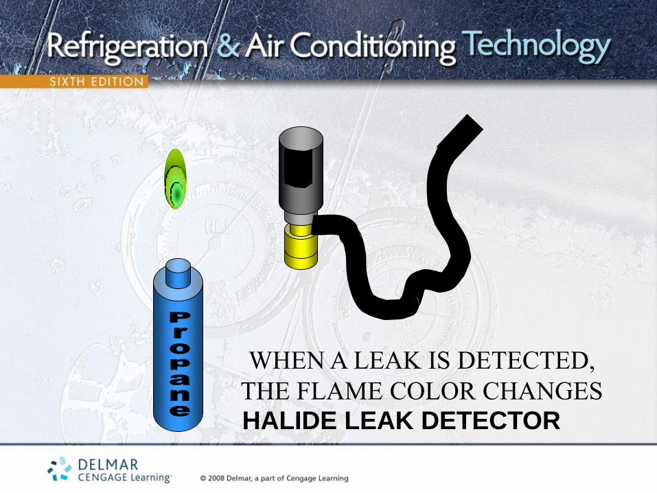
WHEN A LEAK IS DETECTED,
THE FLAME COLOR CHANGES
HALIDE LEAK DETECTOR
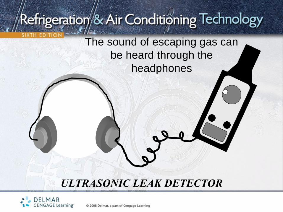
ULTRASONIC LEAK DETECTOR
The sound of escaping gas can
be heard through the
headphones

ULTRAVIOLET LEAK DETECTOR
Ultraviolet dye in the
system glows at the
point of leak when
viewed under
ultraviolet light

ELECTRONIC LEAK DETECTOR
Beeping frequency increases
when a leak is detected
LEAK DETECTING TIPS
• Newly installed systems should be leak tested with a standing pressure test
• The system must be evacuated to required vacuum levels
• Refrigerant/nitrogen mixes cannot be recovered
• Visual inspection for oil and dirt spots
• Leaks can be caused by vibration or temperature
• Leak check gage ports prior to gage installation
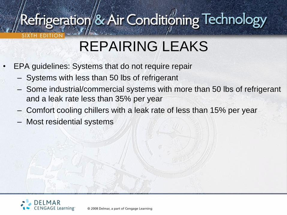
REPAIRING LEAKS
• EPA guidelines: Systems that do not require repair
– Systems with less than 50 lbs of refrigerant
– Some industrial/commercial systems with more than 50 lbs of refrigerant
and a leak rate less than 35% per year
– Comfort cooling chillers with a leak rate of less than 15% per year
– Most residential systems

PURPOSE OF SYSTEM
EVACUATION • Air contains oxygen, nitrogen, hydrogen, water vapor
• Nitrogen is a non-condensable gas
• Non-condensables will cause a rise in the system’s operating head pressure
• Oxygen, hydrogen, and water vapor cause chemical reactions in the system
• Produces acids that deteriorate system components and can cause copper
plating
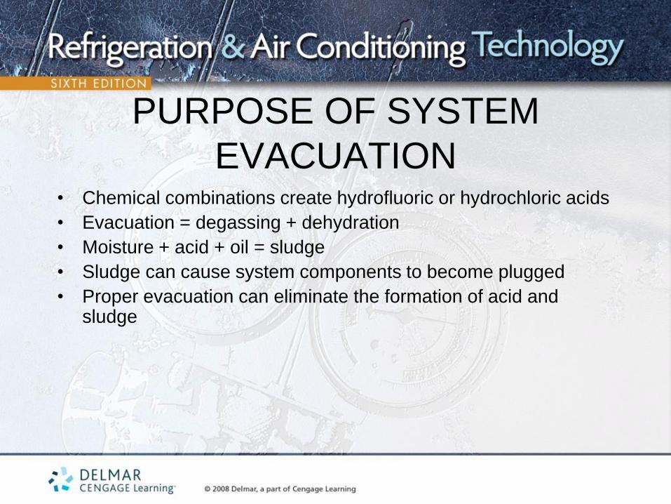
PURPOSE OF SYSTEM
EVACUATION • Chemical combinations create hydrofluoric or hydrochloric acids
• Evacuation = degassing + dehydration
• Moisture + acid + oil = sludge
• Sludge can cause system components to become plugged
• Proper evacuation can eliminate the formation of acid and sludge

THEORY INVOLVED WITH
EVACUATION • Pulling a vacuum lowers the pressure in a system below atmospheric
• Atmospheric pressure = 14.696 psia
• Psia = atmospheric pressure + gage pressure (psig)
• Pulling a vacuum removes non-condensable gases from a system
• Systems should be evacuated from the high and low pressure sides of the system
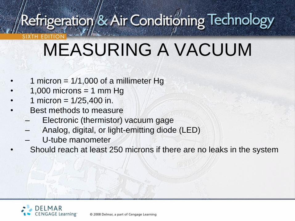
MEASURING A VACUUM
• 1 micron = 1/1,000 of a millimeter Hg
• 1,000 microns = 1 mm Hg
• 1 micron = 1/25,400 in.
• Best methods to measure
– Electronic (thermistor) vacuum gage
– Analog, digital, or light-emitting diode (LED)
– U-tube manometer
• Should reach at least 250 microns if there are no leaks in the system
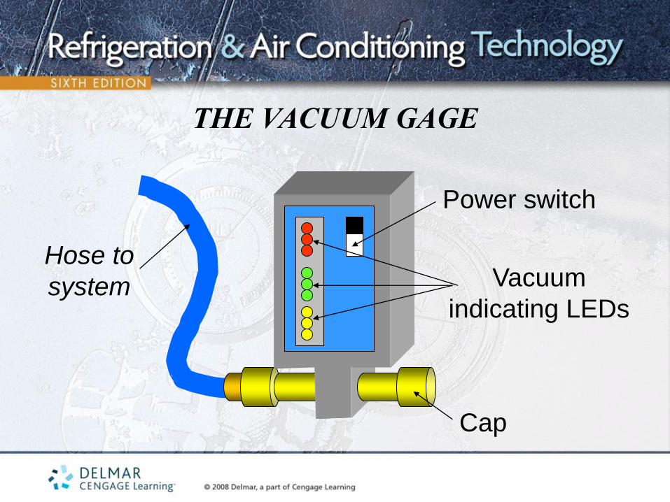
THE VACUUM GAGE
Hose to
system
Cap
Power switch
Vacuum
indicating LEDs

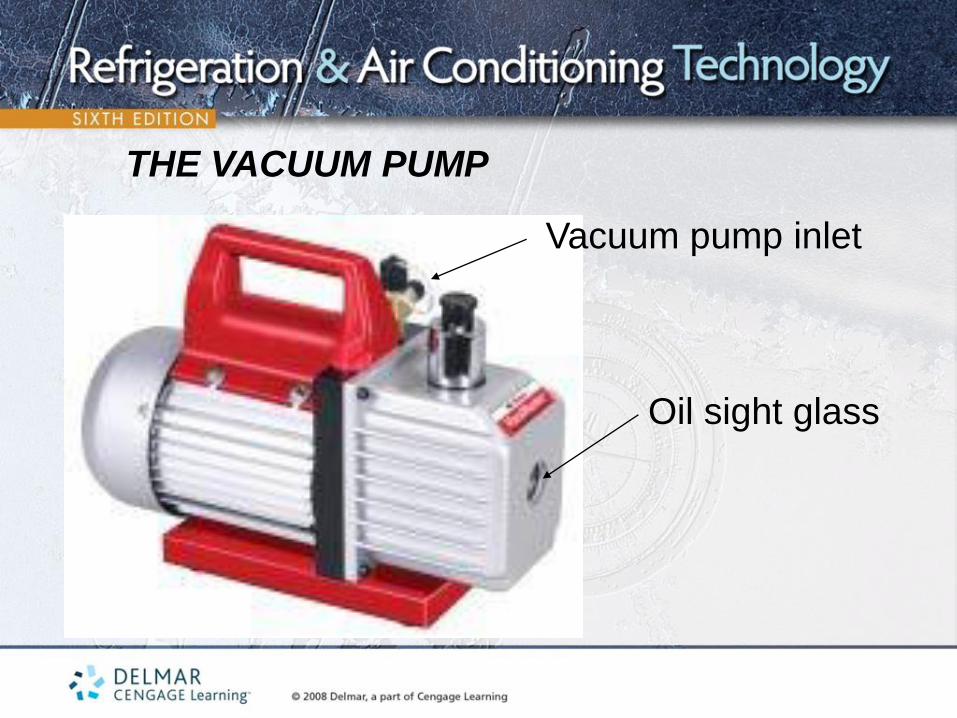
THE VACUUM PUMP
• Two-stage vacuum pumps produce the lowest vacuum
• EPA mandates systems reach at least 500 microns during evacuation
• Very low vacuums cause moisture inside a sealed system to boil to a vapor which is then removed by the pump and released to the atmosphere
THE VACUUM PUMP
Oil sight glass
Vacuum pump inlet

DEEP VACUUMS• Measured in the 250- to 50-micron range
• Once proper micron levels are reached, the vacuum pump is valved off
• When system pressure is reduced to the required vacuum level and remains
constant, no non-condensable gas or moisture is left in the system
LEAK DETECTION WHILE IN A
VACUUM • Checking for a leak in system by watching to see if the pressure rises on a
vacuum gage is not a recommended leak-test procedure
• If there is a leak during the above-mentioned problem, air is allowed to enter the system
• This method only proves that the system will not leak under a pressure difference of 14.696 (atmospheric pressure)

GENERAL EVACUATION PROCEDURES
• Cold trap
• Do not start a hermetic compressor while it is in a deep vacuum
• Applying heat to the compressor will assist in removing water that may be trapped under the oil
• Gage manifolds with large valve ports and hoses help speed the evacuation process
• Schrader stem depressors can be removed from gage hoses to reduce evacuation time
SYSTEMS WITH SCHRADER
VALVES• Take longer to evacuate than systems with service valves
• Field service valves are used to replace Schrader valve stems while the
system is under pressure
• Schrader valve caps should be put back on the valve after service
GAGE MANIFOLD HOSES AND
SYSTEM VALVES• Hoses can have pinhole leaks and slow down the evacuation process
• Using copper tubing for the gage lines will help eliminate evacuation problems
• Check system valves to verify they are open before evacuation
• Closed valves can trap air in the system

USING DRY NITROGEN • Sweeping dry nitrogen through a sealed system
– Helps keep the atmosphere out of the system
– Helps clean the piping of the system
• Do not pressurize the system with pressures that are above the
system’s test pressures
• Never start a system that is pressurized with nitrogen

CLEANING A DIRTY
SYSTEM • Formation of acid, soot and sludge
• Created by heat that causes refrigerant and oil to break down
• Cannot be removed from a system with a vacuum pump
• Fumes can be toxic
• Safety goggles and gloves should be worn
UNIT SUMMARY - 1• The standing pressure test involves pressurizing the system with dry
nitrogen and then monitoring the system pressure
• Common leak detection methods include the halide torch, ultrasonic leak detector, electronic leak detector and the ultraviolet leak detector
• System evacuation removes moisture from the system prior to putting the system into operation
• Evacuation reduces the formation of acid and sludge
UNIT SUMMARY - 2• Evacuation removes system non-condensables
• Vacuums can be measured with micron gauges
• 1 micron = 1/1,000 of a millimeter Hg
• Evacuation = Dehydrating + Degassing
• Systems should not be leak checked in a vacuum
• Removing Schrader valves and pin depressors will help to speed the
evacuation process