section 3.11: cargo transfer and transhipment systems ... · section 3.11: cargo transfer and...
TRANSCRIPT
Section 3.11: Cargo Transfer and Transhipment Systems
TERMPOL Surveys and Studies
ENBRIDGE NORTHERN GATEWAY PROJECT
FINAL - REV. 0
Prepared for: Northern Gateway Pipelines Inc.
January 20, 2010

Northern Gateway Pipelines Inc. Section 3.11: Cargo Transfer and Transhipment Systems Table of Contents
January 20, 2010 FINAL - REV. 0 Page i
Table of Contents
1 Objectives ...................................................................................................... 1-1 2 Cargo Transfer Systems ................................................................................. 2-1
2.1 Vessel Cargo Containment and Transfer Systems ........................................... 2-1 2.2 Terminal Cargo Transfer System...................................................................... 2-2
2.2.1 Marine Loading Arms .................................................................................... 2-2 2.2.2 Ship Manifold and Loading Arm Connection ................................................. 2-4 2.2.3 Marine Loading Arm Operating Envelope ..................................................... 2-4 2.2.4 Onshore Booster Pumps ............................................................................... 2-5 2.2.5 Electrical Discontinuity between Ship and Terminal...................................... 2-5
2.3 Vapour Emissions Control System ................................................................... 2-5 2.4 Segregated and Dirty Ballast Treatment Facilities ............................................ 2-8
2.4.1 Segregated Ballast ........................................................................................ 2-8 2.4.2 Dirty Ballast.................................................................................................... 2-8
2.5 Tank Washing and Slops Treatment Facilities .................................................. 2-8
2.5.1 Tank Washing ................................................................................................ 2-8 2.5.2 Cargo Slops ................................................................................................... 2-8 2.5.3 Engine Room Slops (Bilge Water) ............................................................... 2-10
3 Safety Monitoring and Alarm Systems ............................................................. 3-1
3.1 Temperature Sensors and Alarms .................................................................... 3-1 3.2 Gas Alarm System ........................................................................................... 3-1 3.3 Tanker Berth Safety Warning Systems ............................................................. 3-1 3.4 Fire Detection and Fire Fighting Systems ......................................................... 3-1 3.5 Control Room Monitoring Systems ................................................................... 3-2
3.5.1 Loading Arms, Gas Sensors, and Fire Detection .......................................... 3-2 3.5.2 Communication Systems ............................................................................... 3-3 3.5.3 Automatic and Manual Shut-down ................................................................. 3-3 3.5.4 Cargo Pressures, Temperatures and Transfer Rates ................................... 3-3 3.5.5 Activating a Fixed Fire Protection Device ...................................................... 3-3 3.5.6 Safety Equipment Storage ............................................................................. 3-3
3.6 Emergency Power Supply ................................................................................ 3-4
Northern Gateway Pipelines Inc. Section 3.11: Cargo Transfer and Transhipment Systems Table of Contents
Page ii FINAL - REV. 0 January 20, 2010
Table of Contents (continued) 4 Cargo Transfer Operations ..............................................................................4-1
4.1 General Cargo Transfer Procedures ................................................................. 4-1
4.1.2 Pre-Arrival Activities ...................................................................................... 4-1 4.1.3 Pre-Mooring Activities .................................................................................... 4-2 4.1.4 Mooring of Vessel .......................................................................................... 4-3 4.1.5 Canadian Customs and Custody Transfer .................................................... 4-3
4.2 Discharging of Imported Condensate ................................................................ 4-3
4.2.1 Pre-transfer Activities .................................................................................... 4-3 4.2.2 Pre-Cargo Transfer Circulation Test .............................................................. 4-4 4.2.3 Cargo Discharge Operation ........................................................................... 4-4 4.2.4 Inert Gas Injection .......................................................................................... 4-5 4.2.5 Ballasting Operation ...................................................................................... 4-5
4.3 Loading of Exported Oil .................................................................................... 4-5
4.3.1 Pre-Transfer Activities ................................................................................... 4-6 4.3.2 Pre-Cargo Transfer Circulation Test .............................................................. 4-6 4.3.3 Cargo Loading Operation .............................................................................. 4-6 4.3.4 Ballasting Operation ...................................................................................... 4-7
4.4 Pre-Departure Activities .................................................................................... 4-7 4.5 Unmooring of Vessel ........................................................................................ 4-8 4.6 Purging, Venting and Inerting Cargo Lines ........................................................ 4-8
4.6.1 Draining of Loading Arms .............................................................................. 4-8 4.6.2 Purging of Onshore Pipelines ........................................................................ 4-8
4.7 Ship Access during Transfer Operations ........................................................... 4-8 4.8 Ship and Terminal Security ............................................................................. 4-10 4.9 Bunkering, Ship Repair, and Provisioning ....................................................... 4-10
5 References .....................................................................................................5-1
Northern Gateway Pipelines Inc. Section 3.11: Cargo Transfer and Transhipment Systems Table of Contents
January 20, 2010 FINAL - REV. 0 Page iii
List of Figures
Figure 2-1 Typical Marine Loading Arms Connected to a Ship’s Manifold ............... 2-3 Figure 2-2 Vapour Recovery Unit ............................................................................ 2-7 Figure 4-1 Typical Telescoping Vessel Gangway Access Tower ............................. 4-9

Northern Gateway Pipelines Inc. Section 3.11: Cargo Transfer and Transhipment Systems Section 1: Objectives
January 20, 2010 FINAL - REV. 0 Page 1-1
1 Objectives The objective of this study is to assess the suitability of the terminal facilities for transferring oil products from shore to ship and condensate products from ship to shore by providing the following plans and descriptions:
• The design vessel’s cargo containment and transfer systems.
• The onshore components of the cargo transfer system.

Northern Gateway Pipelines Inc. Section 3.11: Cargo Transfer and Transhipment Systems Section 2: Cargo Transfer Systems
January 20, 2010 FINAL - REV. 0 Page 2-1
2 Cargo Transfer Systems
2.1 Vessel Cargo Containment and Transfer Systems The ship’s cargo containment and transfer system consists of a series of tanks, pipes and pumps (See TERMPOL Study 3.9 Section 2.10 for Ship Specifications). The cargo is contained in the ship’s tanks, which consist of a series of separate compartments within the ship’s inner hull. Cargo can be transferred from the tanks via pipes located in the bottom of each tank compartment. The pipes run from the bottom of each tank to pipe manifolds on the ship’s deck, where the actual connection between the ship and the onshore facilities is made. Tankers are typically equipped with manifolds on both their starboard side and port side to allow the ship to berth at the terminal with either a starboard-to or port-to orientation.
In order to discharge the tanks to the shore facilities, the cargo must be pumped from the bottom of the tanks up to the pipe manifolds on the ship’s deck. Typically a tanker is equipped with three or four cargo pumps located in a pump room immediately forward of the engine room near the ship’s stern and at the end of the tank section. Some Aframax class vessels are equipped with several pumps of a type called a “deep well pump” which are actually located within the cargo tanks and are operated by hydraulics. The ship’s pumps have the power to move the cargo from the tanks to the deck manifold and on to the shore side distribution system. The following cargo transfer pump ratings are typical for the proposed design vessels:
• Aframax: 3 pumps each at 1800 to 3000 m3/hr capacity or 6 or more “Deep Well Pumps” each at 100 to 1500 m3/hr.
• Suezmax: 3 or 4 pumps each at 3500 to 4000 m3/hr capacity.
• VLCC: 3 or 4 pumps each at 5500 m3/hr capacity.
Tankers will have a boiler to manufacture power for the steam turbines, which in turn provide power to the cargo pumps. Alternately, a tanker may have electric motor-driven cargo pumps which are powered by diesel generators. Typically a tanker is equipped with three service generators which supply the electric power for all tanker operations. All generators need not operate simultaneously providing a certain redundancy in case one breaks down. Electrical power can also be generated using steam driven turbo-alternators if the ship is so equipped.
An important part of the tankers cargo system is Inert Gas Generation. The Inert Gas System (IGS) is used to inert the atmosphere within the cargo tanks, as the cargo is pumped to the terminal (See Section 4.2.4).
When cargo is loaded into the ship’s tanks, it bypasses the ship’s pumps and feeds directly into the cargo tanks via gravity. As the tanks are loaded, the air space and vapours inside them, including inert gas, are displaced by the incoming cargo. These vapours will be collected and processed by a Vapour Emission Control System (VECS) where the cargo tank vapours are sent to collection tanks on shore to be treated (See Section 2.3).
Northern Gateway Pipelines Inc. Section 3.11: Cargo Transfer and Transhipment Systems Section 2: Cargo Transfer Systems
Page 2-2 FINAL - REV. 0 January 20, 2010
The tankers load and discharge process is controlled by a Deck Officer usually located in the vessels Cargo Control Room (CCR). This is done in concert with the Kitimat Terminal shore control room. The system used to control cargo operations is typically a combination of mechanical, hydraulic and electronic automated systems that provides cargo personnel with the ability to fully monitor operations, and gives adequate warnings when tanks are full or pumps are not operating correctly.
2.2 Terminal Cargo Transfer System The topside equipment and systems (topsides) will provide all the pipelines, valves, fire protection, vessel access, and control systems required to safely transfer the cargo and crew between the land facility and the tanker. This includes the supporting structures and infrastructure needed to ensure a safety connection. The topsides are designed concurrently with the marine structures allowing certain topside elements to be incorporated into the marine structures as appropriate. All topside equipment will be controlled by the central control room located onshore near the water. Topside equipment and systems can be categorized into cargo transfer systems, safety and security systems, emergency response systems, vessel services, and control systems.
The onshore cargo transfer system includes marine loading arms, manifolds, pipelines, booster pumps and valves. All cargo pipelines and hoses connecting the ship to the marine terminal will conform to industry standards. The onshore transfer equipment will be mounted to the decks of the loading platforms for each tanker berth. The actual connection between the ship and the marine terminal will be made with the use of marine loading arms. The loading arms feed into an adjacent onshore manifold which controls the flow of product being transferred through the system. The onshore manifold in turn is connected to pipelines running on the platform deck and along the access trestle to the onshore tank facilities. For the proposed project there will be two pipelines between the manifold and the onshore facilities, one dedicated for oil products and the other dedicated for condensate products.
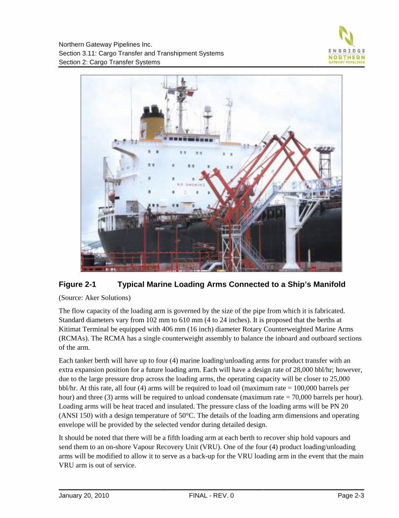
2.2.1 Marine Loading Arms Marine loading arms are special components of the cargo transfer system which are designed to be directly connected to the ship’s manifold. They consist of articulated pipe assemblies which have the ability to swivel in all directions. As such the loading arms can accommodate the movements of a moored ship, including those from tides, while maintaining a secure seal for leak-free cargo transfer. Marine loading arms are standard equipment for most marine oil terminals around the world. A typical loading arm assembly is shown in Figure 2-1 below.
Northern Gateway Pipelines Inc. Section 3.11: Cargo Transfer and Transhipment Systems Section 2: Cargo Transfer Systems
January 20, 2010 FINAL - REV. 0 Page 2-3
Figure 2-1 Typical Marine Loading Arms Connected to a Ship’s Manifold (Source: Aker Solutions)
The flow capacity of the loading arm is governed by the size of the pipe from which it is fabricated. Standard diameters vary from 102 mm to 610 mm (4 to 24 inches). It is proposed that the berths at Kitimat Terminal be equipped with 406 mm (16 inch) diameter Rotary Counterweighted Marine Arms (RCMAs). The RCMA has a single counterweight assembly to balance the inboard and outboard sections of the arm.
Each tanker berth will have up to four (4) marine loading/unloading arms for product transfer with an extra expansion position for a future loading arm. Each will have a design rate of 28,000 bbl/hr; however, due to the large pressure drop across the loading arms, the operating capacity will be closer to 25,000 bbl/hr. At this rate, all four (4) arms will be required to load oil (maximum rate = 100,000 barrels per hour) and three (3) arms will be required to unload condensate (maximum rate = 70,000 barrels per hour). Loading arms will be heat traced and insulated. The pressure class of the loading arms will be PN 20 (ANSI 150) with a design temperature of 50°C. The details of the loading arm dimensions and operating envelope will be provided by the selected vendor during detailed design.
It should be noted that there will be a fifth loading arm at each berth to recover ship hold vapours and send them to an on-shore Vapour Recovery Unit (VRU). One of the four (4) product loading/unloading arms will be modified to allow it to serve as a back-up for the VRU loading arm in the event that the main VRU arm is out of service.
Northern Gateway Pipelines Inc. Section 3.11: Cargo Transfer and Transhipment Systems Section 2: Cargo Transfer Systems
Page 2-4 FINAL - REV. 0 January 20, 2010
2.2.2 Ship Manifold and Loading Arm Connection Each loading arm will be equipped with a hydraulic Emergency Release Couplings/Powered Emergency Release Couplings (ERC/PERC). These couplings allow for a connection between the loading arm and various diameters of ship manifolds without the need for special adaptors. They also allow for a rapid connection to begin cargo operations or disconnection in the case of emergency. During emergencies, the ERC/PERC system, which includes fast-acting, hydraulically actuated ball valves, will stop material flow before the arms are automatically de-coupled from the ship manifold.
There are two loading arm connection options being considered for the project. The first option consists of using Chiksan Quick Connect/Disconnect Couplers (QCDC) for the loading arm connections. These couplers are hydraulically driven and use three clamps to connect the arms to the ship’s manifold facilitating rapid coupling. Each clamp is powered by a reversible hydraulic motor that is connected to a mechanical linkage that operates the clamp. Each motor is hydraulically connected to ensure simultaneous operation of the clamps. In case of a power or hydraulic failure, the coupler fails safe and remains securely fastened to the ship’s manifold. An O-ring fitted into the coupler flanges provides positive sealing. The flanges on the QCDC are rated for AMSE Class 150 applications.
The second option consists of using Chiksan manual Quikcon couplings. These couplings are manually operated, utilizing multiple large hex-headed clamping jaws that rotate onto the mating flanges of the ship manifold and seal into place via an o-ring fitted into the coupling flange. The coupling is available for corrosive or non-corrosive service, with a temperature range of 100°C to -162°C. The flanges on the Quikcon are rated for ASME Class 150 applications.
The final option will be selected during the detailed design stage and will be based on vendor recommendations and the Operational and Maintenance review by Enbridge.
2.2.3 Marine Loading Arm Operating Envelope Marine loading arms have an operating range which is established based on the required ship movement envelope. When the arm is connected to a moored tanker, movement can be caused by numerous effects including: tidal fluctuations; wind, wave, and current forces on the vessel; and changes in vessel draught as it is loaded or unloaded.
The marine arms are equipped with a variety of alarms and systems designed to monitor the arm’s position and provide warnings when the maximum operation envelope is reached. An Integrated Position Monitoring System (IPMS) is used in conjunction with an Over Travel Alarm to monitor the arms and provide a multi-stage alarm system.
The maximum operation envelope for arm movements would be in the order of ±1.5 m for surge (motion along the berth) and sway (motion away from the berth). The maximum physical limit for arm movements would be in the order of ±3.0 m for surge and sway motions, based on criteria for maximum vessel displacements as recommended by PIANC [Reference 1].
A visual and audible pre-alarm is used to alert the operator that the ship is drifting and to tighten the mooring lines.
Northern Gateway Pipelines Inc. Section 3.11: Cargo Transfer and Transhipment Systems Section 2: Cargo Transfer Systems
January 20, 2010 FINAL - REV. 0 Page 2-5
The first step alarm is an audible and visual alert that lets the operator know that the first boundary in the operating envelope has been reached. A hydraulic pump will activate to drain the loading arms while the product pumps are stopped and the control valves closed to stop product transfer. The arms are now ready to be disconnected.
The second step alarm is an audible and visual alarm which alerts the operator that the powered Emergency Release Coupling (PERC) is opened and the arm disconnects from the ship’s manifold.
The operating envelope and alarm locations are dependent on the size and dimensions of the loading arms and will be developed during the detailed design phase.
2.2.4 Onshore Booster Pumps Since the onshore tank facilities are located at a much higher elevation than the marine berths, the cargo pumps on board the ship will not have enough power to transfer condensate cargo all the way to the onshore tanks when unloading the ship. Onshore booster pumps will be required to help overcome the hydraulic head difference between the onshore tanks and the marine berths. Because the discharge capability of the overall system is so greatly influenced by the hydraulic head difference, the design and efficiency of the in-line booster pumps is critical. It is estimated that three 3000 kW (4000-hp) booster pumps (two operating and one spare) are required. It should be noted that the booster pumps are not required when loading cargo onto the ship, since this is done by gravity feed.
2.2.5 Electrical Discontinuity between Ship and Terminal For the proposed loading arms, the electrical resistance of the insulating flange face of the loading arm coupling shall be no less than 10,000 ohms in order to protect against stray currents.
More specific details of the electrical discontinuity arrangements for the loading arms will be developed in the detailed design phase once the final loading arm vendor has been selected.
2.3 Vapour Emissions Control System Vessels destined to be loaded at Kitimat Terminal will arrive with the cargo tanks either entirely or partially empty. When a vessel’s cargo tanks are empty of liquid cargo, the space is occupied with vapours. Although these vapours will mainly consist of inert gas, they will also contain other elements including volatile organic compounds (VOCs).
As the terminal loads liquid cargo into the vessel’s tanks, these vapours are required to be simultaneously discharged. The vapours can either be vented into the atmosphere or captured and processed. Kitimat Terminal will use a Vapour Recovery Unit (VRU) as part of its Vapour Emission Control System to capture and process the vapours from the vessel’s cargo tanks.
The preliminary design of the VRUs uses two sets of activated carbon drums to provide uninterrupted service in capturing VOC vapours from the vessel cargo tanks. The two sets of carbon drums alternate in online service. While one set of carbon drums is used to adsorb hydrocarbons, the other set regenerates.
Northern Gateway Pipelines Inc. Section 3.11: Cargo Transfer and Transhipment Systems Section 2: Cargo Transfer Systems
Page 2-6 FINAL - REV. 0 January 20, 2010
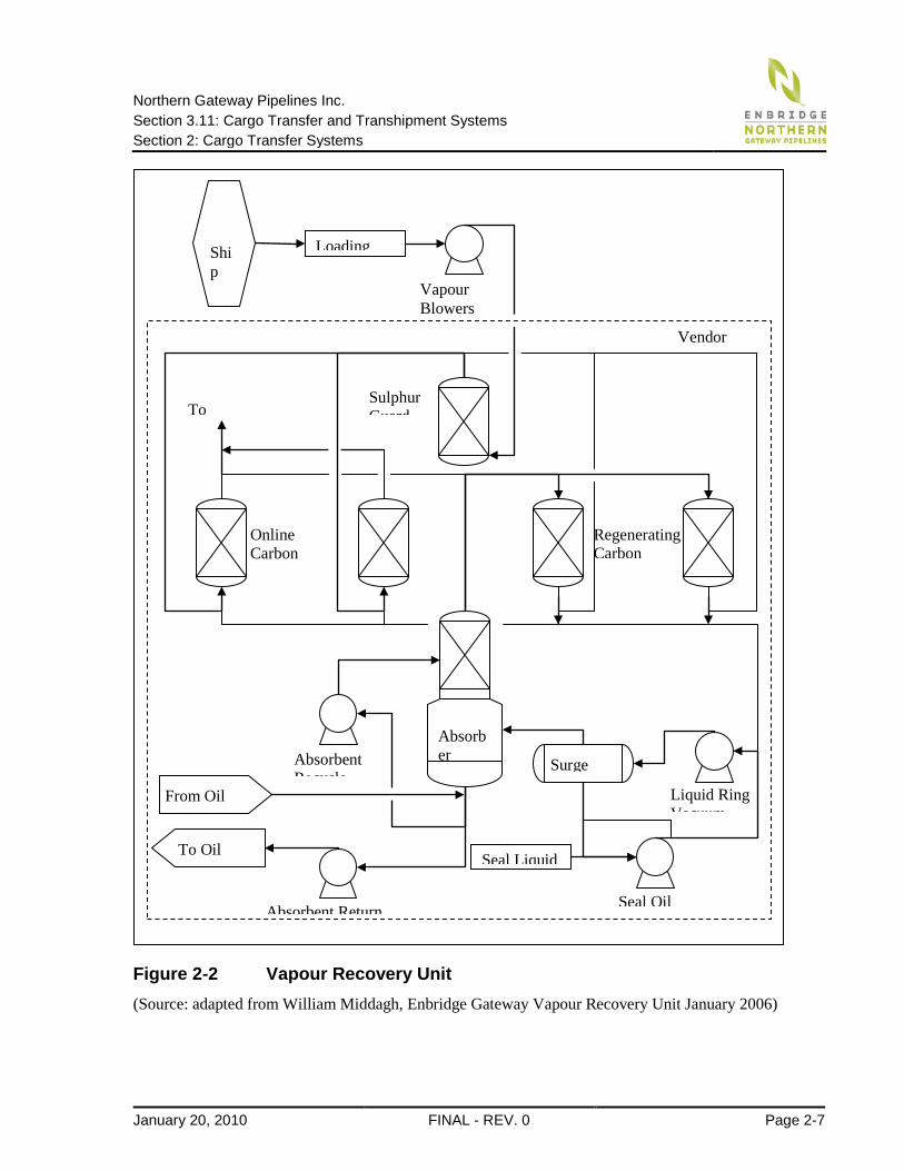
A Process Flow Diagram (PFD) of the VRU is shown in Figure 2-1. The function of the VRUs is described as follows:
1. The vapours from the loading arms are first sent through a sulphur-guard bed to remove H2S, which decreases the effectiveness of the activated carbon beds.
2. The hydrocarbons are subsequently adsorbed by the porous surface area of the activated carbon within the carbon drums. The rate of hydrocarbon adsorption is increased by higher hydrocarbon concentrations, elevated pressures and lower temperatures. A small volume of treated vapour is then emitted into the atmosphere from the carbon drums. The hydrocarbon molecules remain trapped within the carbon drums until the regeneration step.
3. The regeneration step involves desorption or removal of the hydrocarbons from the carbon drums. The rate of desorption increases with decreased pressure, reduced hydrocarbon concentration and increased temperature. The liquid ring vacuum pump provides the required drop in pressure (mild vacuum) to send the hydrocarbon vapours and condensed hydrocarbon liquids from the carbon drums being regenerated to the surge vessel.
4. The surge vessel separates the seal fluid from the recovered hydrocarbon vapour and condenses it to hydrocarbon liquid.
5. The non-condensed hydrocarbon vapours are sent to the absorber tower where liquid hydrocarbons are recovered and sent to the oil tanks.
6. Vapour from the absorber tower containing decreased hydrocarbon concentrations are sent back to the carbon drums being regenerated.
The preliminary design of the VRU is based on an oil loading rate of 100,000 bbl/hr and uses two vapour blowers with capacities of 10,000 SCFM per blower and a 508 mm (20 inch) loading arm. The final configuration and equipment requirements will be determined during the detailed design phase.
Northern Gateway Pipelines Inc. Section 3.11: Cargo Transfer and Transhipment Systems Section 2: Cargo Transfer Systems
January 20, 2010 FINAL - REV. 0 Page 2-7
Figure 2-2 Vapour Recovery Unit (Source: adapted from William Middagh, Enbridge Gateway Vapour Recovery Unit January 2006)
Ship
Loading
Vapour Blowers
Vendor
Surge
Liquid Ring Vacuum
Absorbent Return
Seal Oil
Absorbent Recycle
Seal Liquid
Online Carbon
Sulphur Guard
Regenerating Carbon
To
Absorber
To Oil
From Oil
Northern Gateway Pipelines Inc. Section 3.11: Cargo Transfer and Transhipment Systems Section 2: Cargo Transfer Systems
Page 2-8 FINAL - REV. 0 January 20, 2010
2.4 Segregated and Dirty Ballast Treatment Facilities Kitimat Terminal will have no treatment facilities to receive either segregated ballast or dirty ballast from the tankers. Depending on the nature of the ballast, the tankers will need to follow certain procedures as given in the following sections.
2.4.1 Segregated Ballast During cargo transfer operations, tankers will be allowed to discharge clean segregated ballast into Canadian waters assuming that proper ballast exchange was conducted in the open ocean as per International and Canadian law. The Kitimat Terminal will test the segregated ballast to ensure there are no evasive species present and that the ship has conducted proper ballast exchange in the open ocean. If the tests indicate the segregated ballast does contain evasive aquatic organisms, the tanker will not be allowed to discharge the segregated ballast and will need to retain it onboard (See Section 4.3.3 Cargo Loading Operations).
2.4.2 Dirty Ballast Under no circumstances can dirty ballast be discharged into Canadian waters. Canadian law requires that dirty ballast must be discharged to a proper treatment facility or retained on board the vessel. Also, if the ballast originated from a foreign harbour or port-of-call, it must be retained on the vessel regardless of whether reception facilities are available or not. Since the Kitimat Terminal will have no dirty ballast treatment facility, oil tankers arriving with dirty ballast will be required to retain it onboard and may use either load-on-top or segregated short-loading procedures for loading cargo into the vessel (See Section 4.3.3 Cargo Loading Operations).
2.5 Tank Washing and Slops Treatment Facilities
2.5.1 Tank Washing Cargo tank washing is typically done by rinsing the inside of the tank with cold either or both heated seawater. Sometimes this process may be required due to product incompatibility between previous and future product shipments, or for the purposes of sediment and wax control. Tank washing may also be required to facilitate internal tank inspections and repairs. In either case, the washings or “cargo slops” that are generated are collected and held in the vessel’s dedicated cargo slop tank(s).
Another washing method is Crude Oil Washing (COW) which is a procedure that allows crude oil to be used to assist in the cleaning of a vessel’s cargo tanks in order to control cargo tank residue. COW is typically used at marine terminals that receive oil. Since Kitimat Terminal is strictly exporting oil, it is not expected that COW procedures will be required.
2.5.2 Cargo Slops Kitimat Terminal will have facilities to receive, treat and recover oil from the vessel’s cargo slops. There will be no provisions to receive tank washings from chemical carriers, since no chemical carriers are anticipated to use the terminal.
Northern Gateway Pipelines Inc. Section 3.11: Cargo Transfer and Transhipment Systems Section 2: Cargo Transfer Systems
January 20, 2010 FINAL - REV. 0 Page 2-9
Cargo slops, also known as “wash slops”, is a seawater and oil mixture which can result from a number of cargo related operations including:
• Cargo Slops Generation from Tank Washing: As mentioned previously, cargo tanks may require washing for various reasons such as product incompatibility as well as tank inspections and repairs. The resulting washings or “wash slops" are collected in the cargo slop tanks.
• Cargo Slops Generation from Residual Product: Cargo slops can be generated when residual product is left over inside the empty cargo tanks after a cargo discharge operation. These residuals will naturally drain down the sides and collect at the bottom of the tanks. It is a routine operation to internally strip each of the cargo tanks to a cargo slop tank whist the vessel is on a ballast passage.
• Cargo Slops Generation from Dirty Ballast: Occasionally vessel safety requires that dirty ballast is carried in the cargo tank(s) to maintain ship stability during extreme weather conditions. On cessation of the extreme weather the bulk of the dirty ballast would typically be decanted and discharged to the ocean via a 15 ppm Oily-Water Discharge Monitoring System (ODM) as per MARPOL requirements. The remainder of the dirty ballast would be collected in the cargo slop tanks and allowed to settle before further decanting. After settling, additional water can be separated from the bottom of the cargo slop tanks and discharged to the ocean via the ODM. Any amount of water and oil that cannot be settled out and separated by this process is retained in the cargo slop tanks as ROB (Retained on Board) cargo slops.
• Cargo Slops Generation from Crude Oil Washing (COW): Crude Oil Washing can generate cargo slops that contain undesirable residues, whether they are contaminants from a previous cargo type or excessive sediments. This can occur when a vessel was neither allowed to discharge the slops to shore or to use Load-on-Top (LOT) procedures while at the previous port-of-call. This is not a very common situation. When a tanker does Crude Oil Washing during discharge, washings are commingled and delivered to shore as part of the cargo.
All cargo slops are held in dedicated cargo slop tanks, which are essentially smaller capacity cargo tanks located adjacent to the vessel’s cargo pump room. Any cargo slops that are generated and which cannot be dealt with by decanting or discharged to an onshore treatment facility must be retained in one or more of these dedicated cargo slop tanks. Modern tankers will typically have two or three dedicated cargo slop tanks to assist in the process of settling and separation of the oil and water mixture. It is desirable that the total quantity of cargo slops that are retained on board a vessel are segregated to only one slop tank, unless the quantity is such that more than one tank is required. The cargo slop tanks on a typical VLCC can hold up to 8,000 m3 of cargo slops. Kitimat Terminal’s cargo slop facility will have a capacity to receive and treat up to 10,000 m3 of cargo slops per oil tanker visit.
The oil component of the cargo slop mixture can be recovered and marketed. As such, the cargo slops can be discharged from the vessel to the terminal’s facility using the same cargo pumps and transfer arms that are used to transfer regular cargo. The cargo slop discharge operation takes approximately two to three hours and is typically conducted before regular cargo transfer operations begin.
Northern Gateway Pipelines Inc. Section 3.11: Cargo Transfer and Transhipment Systems Section 2: Cargo Transfer Systems
Page 2-10 FINAL - REV. 0 January 20, 2010
2.5.3 Engine Room Slops (Bilge Water) Engine room slops or bilge water typically consists of a mixture of water, oils, detergents, and other chemicals. A typical VLCC may hold approximately 40 to 50 m3 of engine room slops or bilge water. These potentially noxious mixtures require special treatment and disposal methods. Kitimat Terminal will not provide onsite facilities to treat or dispose of engine room slops. However, the terminal will have provisions for receiving and transferring engine room slops for disposal offsite. This service will be provided by a third party contractor which will use vacuum trucks to receive and transfer the slops to an offsite facility for proper disposal and incineration.
To avoid contamination of the ship’s and terminal’s cargo transfer systems, a separate transfer line will be used to discharge the engine room slops from the vessel. This dedicated line will run from the berth face to the shore end of the tanker berth’s access trestle and will include a flexible transfer hose at the berth face to connect to the ship’s slops/bilge discharge port. The ship’s bilge pump will pump the engine room slops or bilge water to the shore where it will be received by the vacuum truck connected to the other end of line.

Northern Gateway Pipelines Inc. Section 3.11: Cargo Transfer and Transhipment Systems Section 3: Safety Monitoring and Alarm Systems
January 20, 2010 FINAL - REV. 0 Page 3-1
3 Safety Monitoring and Alarm Systems
3.1 Temperature Sensors and Alarms There are no cargo temperature sensors in the berth area. There are temperatures sensors located in the custody transfer metering stations, which are immediately on-shore from the berth trestles.
3.2 Gas Alarm System The preliminary design of the gas alarms has an accuracy of ±3 percent for LEL levels of 0-50 percent and ±5 percentfor LEL levels of 51-100 percent. The H2S alarms have an accuracy of ±2ppm or 10 percent of applied gas, whichever is greater.
The number of alarms will be in accordance with applicable standards and guidelines and will be determined in detailed design.
3.3 Tanker Berth Safety Warning Systems Tanker berth safety warning systems will include separate fire alarm systems and emergency situation alarm systems. The systems will have activation boxes throughout the terminal and will be able to notify terminal personnel through both audible and visual signals. The terminal emergency response plan will outline actions to be taken when the various alarms sound and will also include a response plan to possible oil releases.
The visual and audible warning systems for the berth and the main control rooms will be determined in the detailed design phase and will be in accordance with current industry standards and guidelines.
3.4 Fire Detection and Fire Fighting Systems The fire protection system will have available multiple fire detection alarms and fire fighting systems. All electrical services buildings at the terminal will be equipped with heat detectors and smoke detectors. Individual pump shelters and pump motor units will be equipped with smoke, heat and flame detection equipment. Fire detection will also be provided at each oil tank, each condensate tank, the custody transfer metering station, and at all Quality Assurance (QA) buildings. The loading arms on the berth will be monitored with flame detectors and cameras.
The firefighting systems at the tanker berths will be designed to extinguish fire within the area of the berth platforms and within the immediate vicinity of the loading arm connection to the ship’s manifold. The fire water for the primary fire fighting system will be supplied from the fire water pond via a redundant closed loop line. There will be water and foam monitors located on towers on the main loading platforms, and water monitors located on the berthing structures. These monitors are proposed to be operated remotely and to provide coverage of the berth area and ships, as required by current standards and guidelines.
Northern Gateway Pipelines Inc. Section 3.11: Cargo Transfer and Transhipment Systems Section 3: Safety Monitoring and Alarm Systems
Page 3-2 FINAL - REV. 0 January 20, 2010
Foam concentrate for the foam system will be supplied via a mobile foam trailer, which can be positioned to fight fires either at the tanker berths or the upland facilities. The foam trailer can also be used to provide foam at any of the fire hydrants and applied using aspirating foam nozzles and hoses. The mobile foam tank trailer will have capacity for 3.8 m3 (1,000 US gallon) of foam concentrate.
Onshore tanks will be protected from a rim seal fire by a semi-fixed foam system. In the case of a fire, the mobile foam trailer will be connected to a foam solution connection point adjacent to a fire hydrant located outside the containment berms of the tank. The connection will permit foam concentrate to be blended into the water and delivered to foam distribution chambers located around the periphery of each tank roof.
A redundant firewater system that uses seawater as its source will also be provided. The seawater firewater pump will be located on-shore at the head of the berth trestles and will have a by-pass that ties into the main ring header for the berth platform and berthing structures. The size of the pumps and their location will be determined in the detailed design phase. An alternate foam compound will be considered for the seawater firewater source as well.
The tankers will also be equipped with their own on-board fire suppression systems. Although the terminal’s shore-side fire fighting system may not be designed to extinguish a fire onboard the vessel beyond the ship’s manifold area, it can provide some assistance in suppressing a vessel fire. All support tugs will also be classed as fire-fighting capable and will be able to provide assistance in an emergency.
The terminal will have a firefighting plan in place, including firefighting training of terminal personnel. Refuge areas are typically provided in the topsides areas to provide shelter to operations crew in the event of an emergency. A description of the fire fighting system design parameters is given in TERMPOL Study 3.10 Section 4.9.
3.5 Control Room Monitoring Systems The Kitimat Control Centre is the terminal’s central control room located onshore near the water. It will monitor and control the cargo transfer operations at the marine terminal, as well as the associated terminal equipment. This control centre will also provide primary oversight of the entire terminal including the reception of all operating data, the capability of controlling valves and the monitoring of all security systems.
A system redundancy back-up plan will be evaluated for the Kitimat Control Centre during detailed design. It is proposed that an alternate use Control Centre will be tied in as a fully redundant back-up control centre that is separate from the primary site. Operators can direct a controlled shutdown of the system from this location in the event that the primary control centre is unavailable.
3.5.1 Loading Arms, Gas Sensors, and Fire Detection The loading arms will be designed to include continuous fire and gas monitoring.
Northern Gateway Pipelines Inc. Section 3.11: Cargo Transfer and Transhipment Systems Section 3: Safety Monitoring and Alarm Systems
January 20, 2010 FINAL - REV. 0 Page 3-3
3.5.2 Communication Systems The project will use a communication system with redundant equipment and alternate data routes for the controller to maintain control over the terminal, pump stations and remote valve sites.
A combination of wide area network frame relay, telephone lines and satellite communication circuits will provide main and back-up communication systems to remote terminal units (RTUs) at all terminal, pump station and valve locations. Satellite communication circuits use “report by exception” communication, in which RTUs report changes in the terminal or pump station data to the control centre as soon as changes are detected.
The Kitimat Terminal and pump stations will be connected to network services supplied by a qualified service provider. The communications system will be equipped with frame relay and voice communication interfaces. The lines will provide infrastructure for dial-up voice communication and the SCADA data link to the Control Centre, refer to TERMPOL Study 3.10, Section 4.15.
The Kitimat Terminal and pump stations will be equipped with a satellite data link to provide backup SCADA communications. Alternate voice communications required at the terminal for marine operations will be provided, in order to comply with Canadian Marine Transport Security requirements.
Pump stations will have a local Ethernet network to provide an interface between local computer systems and programmable logic controllers.
Network connections inside buildings will use conventional wiring, and links between buildings will use fibre optic cable.
3.5.3 Automatic and Manual Shut-down The automatic and manual shut-down systems will be developed during detailed design. As a minimum requirement, the shutdown systems will be designed to fail in a “fail safe” mode, per industry standards.
3.5.4 Cargo Pressures, Temperatures and Transfer Rates The berths will be equipped with a safety control system that will allow terminal personnel to continuously monitor hydrocarbon transfer operations from the Kitimat Control Centre. The safety control system also allows the terminal personnel to continuously monitor tanker security at the berth, weather information, mooring line forces, and other important vessel safety parameters.
3.5.5 Activating a Fixed Fire Protection Device The procedures for activating the fixed fire protection devices will be developed during detailed design.
3.5.6 Safety Equipment Storage Each berth will have available marine lifesaving equipment capable of rescuing personnel who might fall into the water. The utility boats will also be equipped for rescue operations and safety rules will be established to help prevent accidents. The storage and use of safety equipment will be further developed during detailed design.
Northern Gateway Pipelines Inc. Section 3.11: Cargo Transfer and Transhipment Systems Section 3: Safety Monitoring and Alarm Systems
Page 3-4 FINAL - REV. 0 January 20, 2010
3.6 Emergency Power Supply An emergency power supply for the terminal facilities and infrastructure will be provided through the use of portable emergency generator units. An emergency generator dedicated to each tanker berth will be capable of generating enough power to allow for the safe and orderly shut-down of all operations, and the removal of transfer arms and gangways. The specifics of these generator units including size and power output will be developed in the detailed design phase once the required capacity has been determined.
No infrastructure has been included for emergency power supply to any moored ships.
Northern Gateway Pipelines Inc. Section 3.11: Cargo Transfer and Transhipment Systems Section 4: Cargo Transfer Operations
January 20, 2010 FINAL - REV. 0 Page 4-1
4 Cargo Transfer Operations
4.1 General Cargo Transfer Procedures The cargo transfer procedures at Kitimat Terminal will include the import of condensate and the export of oil. Imported condensate will be transferred from the vessels to the tanks onshore, a procedure commonly referred to as “discharging”, and exported oil will be transferred from the onshore tanks to the vessels, a procedure commonly referred to as “loading”. The products being transferred are owned by third parties (customers) and not by Enbridge Northern Gateway Pipelines which is strictly providing a transhipment service for the products through Kitimat Terminal.
Cargo transfer operations occur as a series of procedures with the common purpose of achieving a safe and efficient transfer of product. Some procedures are common to both discharging and loading of products. Other procedures will be specific, depending on the direction of product movement. The various procedures can be grouped sequentially as follows:
1. Pre-Arrival Activities—common to both discharging and loading operations;
2. Pre-Mooring Activities—common to both discharging and loading operations;
3. Mooring of Vessel—common to both discharging and loading operations;
4. Canadian Customs and Custody Transfer—common to both discharging and loading operations;
5. Loading Arm and Manifold Warming-up/Cooling-Down Procedures—common to both discharging and loading operations;
6. Pre-transfer Activities—specific to direction of cargo transfer;
7. Pre-Cargo Transfer Circulation Test—specific to direction of cargo transfer;
8. Cargo Transfer Operations—specific to direction of cargo transfer;
9. Pre-Departure Activities—common to both discharging and loading operations; and,
10. Unmooring of Vessel—common to both discharging and loading operations.
4.1.2 Pre-Arrival Activities Planning for the discharge or loading of product at the terminal will begin several months prior to the arrival of any given tanker. The terminal will begin to plan for the movement of a specific volume of product by using a nomination system. The terminal will have written procedures to allow customers to nominate, or schedule, movement of product through the terminal at a certain time and at a fixed volume.
Northern Gateway Pipelines Inc. Section 3.11: Cargo Transfer and Transhipment Systems Section 4: Cargo Transfer Operations
Page 4-2 FINAL - REV. 0 January 20, 2010
The type of product and the specific tanker that will be involved may not be known at the time of nomination, since the customer is merely reserving a place within the overall transhipment schedule. The nomination process can begin as early as three months in advance of the actual product shipment. Within this period, there are certain deadlines for proposing a specific tanker. As soon as the name of the tanker is nominated and made known to the terminal, Enbridge will begin the vetting process through its Tanker Acceptance Program (TAP) to determine if the nominated tanker meets the minimum acceptance criteria and can be allowed to call on the facility. Although Enbridge personnel will not physically pre-inspect the tankers, the program will examine all aspects of a tanker’s safety record through the Ship Inspection Report (SIRE) program (See TERMPOL Study 3.9, Section 3).
If the Tanker Acceptance Program finds the vessel acceptable, it will be allowed to berth at the terminal. Tanker acceptance however, does not preclude Enbridge’s right to inspect the tankers once they are berthed at the terminal. Enbridge can and will conduct tanker inspections at the berth for their own future reference. Conversely, if the Tanker Acceptance Program finds information about the tanker which indicates the tanker may not be suitable to meet the requirements of Kitimat Terminal, the tanker will be denied access to the terminal, and the shipper will be requested to nominate another ship.
If the tanker has been accepted by the TAP, it is entered into the scheduling system using the tanker’s Estimated Time of Arrival (ETA). Conflicts in scheduling are addressed by the terminal. In addition to placing the tanker in the schedule, the terminal will make available to the tanker and its owner copies of the Port Information Booklet (See TERMPOL Study 3.16), and the Terminal Regulations (See TERMPOL Study 3.17). The Port Information Booklet will contain information about general marine subjects including pilots, tugs, weather, references to Canadian regulations, and the like. The Terminal Regulations will include mandatory procedures and regulations for the tanker to follow while it is moored at Kitimat Terminal. If the tanker does not follow the regulations, all cargo transfer shall be stopped and the tanker may be required to leave the dock.
4.1.3 Pre-Mooring Activities Prior to the approach to the pilot station, the vessel will begin preparations for mooring and cargo operations. Cargo tanks will be monitored for inert gas pressure and oxygen content. If either is found to be not to required standards, the inert gas system will be activated and the pressure either or both oxygen content will be brought to within standard values. The inert gas status should be reported, maintained, and re-checked upon arrival at the terminal. The cargo steam boilers will be warmed and brought up to temperature in preparation for cargo operations. The ship’s cargo officer will complete the vessel’s cargo transfer plan which must be approved by the ship’s master.
About one hour before the actual mooring operation begins, a conference will be held with the ship’s master, the pilot and the ship’s deck officers to discuss the mooring operation. Positioning of tugs, mooring line sequencing, and mooring position will be agreed upon. The mooring position of the vessel will depend on the weather conditions at the terminal dock, since current and wind are major determinants of whether the vessel will moor starboard or port side to the dock. Environmental monitoring will be conducted at the terminal, thus real time weather values can be reported to the vessel. Communications will be made with the terminal and the assisting tug boats outlining the mooring plan.
Northern Gateway Pipelines Inc. Section 3.11: Cargo Transfer and Transhipment Systems Section 4: Cargo Transfer Operations
January 20, 2010 FINAL - REV. 0 Page 4-3
4.1.4 Mooring of Vessel Approximately 4 to 5 km from the terminal; the harbour tugs will meet the incoming tanker and take their positions to assist in the mooring operation. If escort tugs are attending the ship (e.g., for laden in-bound condensate ships), it may be used to assist in berthing. With the assistance of the harbour tugs and other docking aid systems, the vessel will be manoeuvred alongside the dock and the mooring lines will be deployed. Once the vessel is secure, all tugs will be dismissed and the pilot will leave the vessel. The entire mooring operation will take approximately two hours. See TERMPOL Study 3.13 for a detailed summary of the mooring procedures and berthing strategy.
4.1.5 Canadian Customs and Custody Transfer Once mooring operations are complete and the gangway has been placed on the vessel, Canada Customs officials will access the vessel to finalize the “entering and clearing” process before any cargo transfer can begin. Canada Customs officials will examine the vessels papers, obtain signatures from the ship’s master on required documentation, review the crew, and collect any duties or fees necessary for any vessel not registered under the Canadian flag. This is routine for all non-Canadian flag ships. The entering and clearing process typically takes about one and half hours. Whether cargo transfer preparations can begin during this period is a decision for the Canadian authorities.
Custody transfer includes the changing of legal custody of the cargo between parties and the collection of taxes and fees by the government. Measurement of the amount of cargo transferred is crucial for these activities as well as for detecting leaks in the system. The custody transfer metering system will consist of a metering facility, prover, and quality assurance building. The metering facility will accurately monitor the total flow of cargo being transferred. The quality assurance building will take periodic samples and provide in-line density and viscosity monitoring of the cargo. The prover will be used to regularly confirm and calibrate the accuracy of the meters in the facility. The metering system also includes a computer controlled flow management system used to optimize the accuracy of the various components of the metering system.
Oil and condensate have separate, segregated metering facilities. A single condensate metering system is used for the metering of condensate from either berth. The two oil metering systems are berth specific in order to allow loading oil to two berths simultaneously.
4.2 Discharging of Imported Condensate
4.2.1 Pre-transfer Activities Once the vessel has cleared customs, pre-transfer activities can begin. The following activities can be conducted concurrently:
• Cargo measurement: The cargo in the vessel’s tanks will be measured and sampled, usually by an independent inspector accompanied by a ships officer. Both parties will take cargo measurements for comparison.
Northern Gateway Pipelines Inc. Section 3.11: Cargo Transfer and Transhipment Systems Section 4: Cargo Transfer Operations
Page 4-4 FINAL - REV. 0 January 20, 2010
• Marine loading arms connected: The loading arms at the terminal will be hydraulically powered and can be guided into place with a remote controller. The arms will be equipped with automatic couplers. A terminal employee will board the vessel, and with the assistance of the vessel’s crew, guide the arms to the vessel’s manifold and couple the two together.
• Pre-transfer conference: Perhaps the most important activity during this period is the pre-transfer conference. This conference is attended by the ships master, the chief engineer, the senior officer in charge of cargo operations and by the senior terminal personnel in charge of terminal activities. At the conference they will discuss the cargo transfer plan, the terminal’s requirements, emergency procedures and any other information necessary for the safe transfer of the cargo.
• Pre-transfer inspection: When the pre-transfer conference is completed, the parties will proceed to physically inspect the vessel for readiness and complete the Declaration of Inspection. The Declaration of Inspection is an itemized document which covers all aspects of the cargo transfer operation including safety, emergency procedures and communications. The Declaration of Inspection will have as many as 50 items which must be co-signed by both parties. Upon completion of the inspection, the parties will sign the Declaration of Inspection indicating that cargo transfer operations can be initiated.
4.2.2 Pre-Cargo Transfer Circulation Test Cargo transfer will begin when parties on the vessel and terminal test communications and agree via radio that all systems are ready. A pre-cargo transfer circulation test will be conducted where the initial transfer will begin at a very slow rate, until all the systems are checked for leaks and confirmation is given that cargo is being directed to the intended onshore tanks. Once confirmation is obtained, the vessel will gradually increase the discharge pumping rate under the direction of the terminal until the maximum allowable rate is obtained.
4.2.3 Cargo Discharge Operation The discharge rate can be governed by many factors including the size of the pipeline, the pipeline back-pressure either or both the difference in height (head) between the tanker and the shore tanks. The maximum allowable pipeline back-pressure at Kitimat Terminal will be determined once the topside equipment and pipelines are designed. Vessel pressures will vary depending on the design of the vessel’s cargo transfer system.
Transfer operations can continue for many hours depending on pump size, pipeline size and cargo viscosity. For a modern terminal, the total transfer time is typically 24 to 36 hours. During the discharge period, both the terminal and vessel personnel will make periodic inspections of the water, pipelines, loading arms and tanks to be sure that there are no leaks and that the operation is proceeding normally. They will also exchange, on an hourly basis, the values for the volume of cargo transferred. If there are significant discrepancies, the operation will be stopped and the differences reconciled.
Northern Gateway Pipelines Inc. Section 3.11: Cargo Transfer and Transhipment Systems Section 4: Cargo Transfer Operations
January 20, 2010 FINAL - REV. 0 Page 4-5
Near the completion of the cargo transfer operation, the vessel’s pumps will be slowed to begin the process of discharging the last bit of cargo in the cargo tanks, a procedure known as “stripping”. The ship will typically give terminal personnel 30-minute, 10-minute, and 1-minute notices before completing the discharge operation. In practice, especially where the cargo discharged is of light density and booster pumps must be employed to overcome a large hydraulic head, stripping of the ship’s individual cargo tanks is carried out internally where each tank is stripped successively to the next. This process maintains overall cargo transfer efficiency and ensures that maximum bulk pumping of cargo to the shore facilities continues uninterrupted. Only the final ship’s tank is stripped directly to the shore. When this last bit of cargo is stripped, the transfer operation will be declared finished.
4.2.4 Inert Gas Injection Injection of inert gas into the “ullage” space of a cargo tank being discharged is an extremely important safety process and is conducted simultaneously with the cargo transfer operation. The inert gas maintains the atmosphere in the cargo tanks outside of the explosive or combustible range by keeping the oxygen content in the cargo tanks at less than 8 percent oxygen by volume. Whilst 8 percent oxygen by volume is sufficient to maintain this status, the industry requires a content of less than 5 percent by volume to be maintained throughout cargo operations for vessel and terminal safety.
Inert gas is either produced by scrubbing the flue gas from the ship’s boilers or manufactured with an inert gas generator. The vessel personnel must frequently check the inert gas pressure and confirm the oxygen content in the vessel’s tanks is less than 5 percent. Since the inert gas system is the most important system to prevent explosions on the vessel, it is important for the pressure and oxygen content to be checked on an hourly basis.
4.2.5 Ballasting Operation A ballasting operation is conducted simultaneously with the cargo discharging operation and is initiated shortly after the cargo discharging has begun. This operation involves loading sea water into dedicated ballast tanks of the vessel, which are completely segregated from the cargo tanks. The ballasting operation will continue throughout the cargo transfer operation and is completed prior to unmooring.
4.3 Loading of Exported Oil The pre-arrival activities for cargo loading operations are the same as for cargo discharging operations including tanker nomination and vetting through the terminal’s Tanker Acceptance Program. Pre-mooring activities, mooring procedures, pre-departure activities, and unmooring procedures are also the same. The difference between cargo loading and cargo discharging occurs during the pre-transfer activities and the actual cargo transfer operation. These differences are discussed below.
Northern Gateway Pipelines Inc. Section 3.11: Cargo Transfer and Transhipment Systems Section 4: Cargo Transfer Operations
Page 4-6 FINAL - REV. 0 January 20, 2010
4.3.1 Pre-Transfer Activities Similar to cargo discharge operations, once the vessel has cleared customs, pre-transfer activities for the cargo loading operation can begin. The following activities can be conducted concurrently:
• Tank inspection: An independent inspector will board the vessel. The inspector will examine all cargo tank measuring instruments on the ship to assure the cargo tanks are empty. Typically tankers are fitted with special equipment that allows for the closed measurement or dipping of cargo tanks without the undue release of cargo tank atmosphere. In this way, cargo “innage” can be accurately quantified.
• Cargo transfer arms connected: Same procedure as for cargo discharging operations, see Section 4.2.1.
• Environmental Protection Boom deployed: As a safety measure, prior to oil loading operations, an environmental protection boom will be deployed to contain any product release.
• Pre-transfer conference: Same procedure as for cargo discharging operations, see Section 4.2.1.
• Pre-transfer inspection: Same procedure as for cargo discharging operations, see Section 4.2.1.
4.3.2 Pre-Cargo Transfer Circulation Test The Pre-Cargo Transfer Circulation Test is similar to that described in Section 4.2.2.
4.3.3 Cargo Loading Operation Overall loading rates are typically governed by the vessel’s capability rather than the terminal’s capability. Tanker loading rates are primarily governed by the allowable gas flow rate in the vessel’s inert gas venting system. During loading operations it is critical that vapour pressure is not allowed to build up within the cargo tank’s atmosphere as this can cause physical damage to the tanker’s internal structure.
Clean segregated ballast that has been checked, tested and approved on arrival will be discharged to the sea concurrent with the loading operation.
Loading operations can continue for many hours depending on the vessel’s capability, pipeline size and viscosity of the cargo. For a modern terminal the total loading time is typically 18 to 24 hours. During the loading period both the terminal and vessel personnel will make periodic inspections of the water, pipelines, loading arms and tanks to be sure there are no leaks and the operation is proceeding normally. They will also exchange, on an hourly basis, the values for the volume of cargo transferred. If there are significant discrepancies, the operation will be stopped and the differences reconciled.
Under the direction of the tanker’s cargo officer and before all cargo has been loaded into the vessel, the flow will be slowed to agreed rates to carry out the “topping-off” process. The topping-off process consists of bringing the level of the product to the highest point in the vessel’s cargo tanks. Care must be taken to avoid overflowing the cargo tanks. Thus the ship will typically give terminal personnel 30-minute, 10-minute, and 1-minute notices before completing the transfer operation. Once the final cargo tank is topped-off, the shore valves have been closed, and the loading arms have been drained to the tanker, the transfer operation will be declared finished.
Northern Gateway Pipelines Inc. Section 3.11: Cargo Transfer and Transhipment Systems Section 4: Cargo Transfer Operations
January 20, 2010 FINAL - REV. 0 Page 4-7
4.3.4 Ballasting Operation A vessel arriving at the Kitimat Terminal with its cargo tanks empty will arrive in a “ballasted” condition, where sea water is taken-on as ballast in order to stabilize the ship and allow it to safely operate in the ocean. Modern tankers place the seawater ballast in the space between the inner and outer hulls. The common name for this ballast is “segregated ballast” because it is isolated from the cargo system and cargo tanks. Although segregated ballast is typically oil free and can be discharged directly into the water, it is known to potentially carry evasive species that may not be indigenous to Canadian waters. Therefore, when the tanker is in the open ocean, it must conduct ballast exchange operations, where the ballast that was taken-on from the previous port-of-call is exchanged with water from the open ocean. This procedure reduces the possibility of evasive species entering local Canadian waters through a vessel’s segregated ballast discharge. Canada has strict laws and regulations concerning the discharge of ballast and the Kitimat Terminal will abide by these laws and regulations.
The discharge of segregated ballast into the water is conducted simultaneously with the cargo loading operation and is initiated shortly after the cargo loading has begun. This ballast will be inspected prior to pumping to be sure no petroleum product is floating on the segregated ballast. If any petroleum product is noticed, the transfer of the segregated ballast will not begin.
• Retention of Dirty Ballast - The terminal has no ballast treatment facility. If a ship has dirty ballast, it will need to be retained on the ship. Typically the dirty ballast is retained in a single cargo tank and cargo is loaded in the remaining cargo tanks, keeping the dirty ballast fully segregated. This method, known as ‘Short-loading”, will involve loading less cargo quantity.
4.4 Pre-Departure Activities Upon the completion of the cargo transfer operation, the pre-departure activities will begin as follows:
• Draining of cargo loading arms: The necessary valves are closed and the loading arms will be vented and drained, allowing them to be disconnected from the ship’s manifold without any cargo spillage. The draining process is routine and can be completed very quickly (See Section 4.6.1).
• Disconnection of cargo loading arms: A terminal employee will board the vessel and, using the remote control, disconnect the loading arms from the ship’s manifold and guide them to their stowed position on the dock.
• Retract Environmental Protection Boom: The Environmental Protection Boom will be deployed prior to oil loading operations only. Once oil loading operations are complete, terminal personnel will use the utility boats to retract the boom and stow it underneath or beside the berth structures.
• Cargo tank inspection and cargo measurement: An independent inspector will board the vessel and will inspect each tank to be sure all of the cargo has been discharged from the vessel with respect to a discharge operation or will measure the cargo received by the vessel with respect to a loading operation. The quantity of cargo transferred is also verified by the ship’s staff and compared with the terminal’s figures. Any discrepancy in the cargo transfer amounts is noted.
• Terminal/Agency/ Vessel business: Various cargo papers and documents will be signed, including the vessel’s Customs Clearance to Sail.
Northern Gateway Pipelines Inc. Section 3.11: Cargo Transfer and Transhipment Systems Section 4: Cargo Transfer Operations
Page 4-8 FINAL - REV. 0 January 20, 2010
• Pilot and tugs: The ship’s agent will have given advanced notification to the pilots and tugs to prepare to assist the vessel out of the berth.
• Vessel preparation: Before a vessel can depart, the main engine will be made ready and all necessary ancillary equipment brought up to working condition. Typically the ship’s engineers will require one hour’s notice for preparation to sail. The rudder, navigation equipment and the communications systems between the engine room and the navigating bridge will also be tested or brought into working mode.
4.5 Unmooring of Vessel When the vessel is ready for departure, the pilot will direct the harbour tugs to their positions and proceed to unmoor the vessel from the berth. The mooring lines will be released in a pattern as directed by the pilot. Once the vessel is well clear of the terminal, the harbour tugs will be dismissed by the pilot and the escort tug(s) will assume their position for the transit to the open sea.
4.6 Purging, Venting and Inerting Cargo Lines
4.6.1 Draining of Loading Arms Once the cargo transfer operations are complete, the loading arms have the means to be vented and drained, allowing them to be disconnected from the ship’s manifold without any cargo spillage. Each loading arm is equipped with a gate valve designed to isolate the coupling and the rest of the arm from the product lines running to the tank terminal. The arm itself can be drained and vented through two drain ports, one located at the bottom of the base riser and one at the terminal swivel assembly. A vacuum breaker system is employed to relieve any vacuum pressure created by draining operations and is located at the apex swivel at the top of the arm assembly. After oil loading operations are complete, the outboard section of the loading arm is typically drained to the ship and the inboard section is drained to the recovered oil drain tank.
4.6.2 Purging of Onshore Pipelines In general, for the onshore marine terminal, lines and vessels will be purged with inert gas and vented before the start of maintenance activities. Oil and condensate lines will be equipped with drains that allow the controlled transfer of product to the recovered oil drain tank. The lines will also be equipped with a vent system which can be used to move vapour to/from the vapour space in the recovered oil drain tank or purge a line with inert gas.
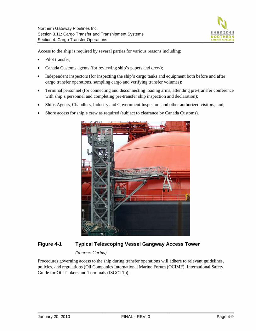
4.7 Ship Access during Transfer Operations To allow access to the ship, each tanker berth will be equipped with an elevating gangway tower located on one of the berth structures. The telescoping gangway will have the ability to move in all directions to accommodate ship movement caused by tidal fluctuations, ship’s trim, changes in tanker draft, and environmental loads. Typically the gangway will land on the ship’s deck to one side of the manifold or other depending on the orientation of the moored vessel. A typical ship’s gangway tower is shown in Figure 4-1. below. A portable light-duty access gangway will be available as a back-up in case one of the primary gangways breaks down. Access can also be provided using the ship’s on-board gangway or pilot boarding ladders if necessary.
Northern Gateway Pipelines Inc. Section 3.11: Cargo Transfer and Transhipment Systems Section 4: Cargo Transfer Operations
January 20, 2010 FINAL - REV. 0 Page 4-9
Access to the ship is required by several parties for various reasons including:
• Pilot transfer;
• Canada Customs agents (for reviewing ship’s papers and crew);
• Independent inspectors (for inspecting the ship’s cargo tanks and equipment both before and after cargo transfer operations, sampling cargo and verifying transfer volumes);
• Terminal personnel (for connecting and disconnecting loading arms, attending pre-transfer conference with ship’s personnel and completing pre-transfer ship inspection and declaration);
• Ships Agents, Chandlers, Industry and Government Inspectors and other authorized visitors; and,
• Shore access for ship’s crew as required (subject to clearance by Canada Customs).
Figure 4-1 Typical Telescoping Vessel Gangway Access Tower (Source: Carbis)
Procedures governing access to the ship during transfer operations will adhere to relevant guidelines, policies, and regulations (Oil Companies International Marine Forum (OCIMF), International Safety Guide for Oil Tankers and Terminals (ISGOTT)).
Northern Gateway Pipelines Inc. Section 3.11: Cargo Transfer and Transhipment Systems Section 4: Cargo Transfer Operations
Page 4-10 FINAL - REV. 0 January 20, 2010
4.8 Ship and Terminal Security The Northern Gateway terminal and the visiting vessels are also required by law to comply with the provisions of the International Maritime Organization (IMO’s) International Ships and Port Facility Security (ISPS) Code. In Canada, the ISPS code is regulated by Transport Canada.
Among other things, the ISPS code requires that the terminal prepare a Port Facility Security Assessment, which identifies site-specific critical infrastructure elements, as well as potential threats, vulnerabilities, and available countermeasures. The Security Assessment forms part of the Port Facility Security Plan, which includes among other things the following topics:
• measures to prevent unauthorized weapons or any other dangerous substances from being introduced into the port facility or on board a ship
• measures designed to prevent unauthorized access to the port facility or ships moored at the facility
• Response to security threats or breaches of security, maintaining critical operations, evacuation procedures
• duties of port facility security personnel and procedures for interfacing with ship’s security officers
• procedures for periodically reviewing and updating the Security Plan
• measures to maintain the confidentiality of the Security Plan itself
• measures to ensure effective security of cargo and the cargo handling equipment
• procedures for facilitating shore leave for ship's personnel or personnel changes, as well as access of visitors to the ship including representatives of seafarers welfare and labour organizations.
Facility security measures may include perimeter fencing, intrusion alarms, surveillance systems, and lighting. Northern Gateway will work with local and federal policing authorities and industry associations to identify and monitor trends and issues.
In a similar fashion, all vessels are also required to have in place a Ship Security Assessment and Ship Security Plan, which is documented and verified through an International Ship Security Certificate.
4.9 Bunkering, Ship Repair, and Provisioning There are no provisions for bunkering (taking on ship’s fuel) or ship repair at Kitimat Terminal. Provision will be made to supply potable water for the ships via a hose connection to the main terminal potable water supply. Loading of provisions and other ship’s stores will be facilitated from the central platform using either a jib crane mounted on the vessel gangway tower, or by using the ship’s on-board crane to lift parcels delivered by truck to the berth area. Any transfer of ship’s stores will be subject to terminal operating restrictions. For example, no provisioning will be permitted during the cargo transfer operations.
Northern Gateway Pipelines Inc. Section 3.11: Cargo Transfer and Transhipment Systems Section 5: References
January 20, 2010 FINAL - REV. 0 Page 5-1
5 References 1. PIANC: “Criteria for Movement of Moored Ships in Harbours: A Practical Guide”, 1995.
2. 3Si Risk Strategies Incorporated. Enbridge – Northern Gateway Kitimat Terminal, Marine Facility Security Overview. November 2009.