section 7: corn reels - patriot equip
TRANSCRIPT

Corn Reel BY
Patriot Equipment
Installation
Operation
Manual
Minden Machine Shop Inc. 1302 K Road Minden NE 68959 1-308-832-0220

Corn Reel Manual
Table of Contents
Contents Page Number
Safety and Operation Rules 3
Machine Inspection 6
Safety Decals 6
Assembly Instructions 8
Test Run 9
Operation 9
Parts Diagrams 10
Corn Reel Mounts 13
Torque Table 22
Machine Measurements 23
Warranty 32
Corn Reel V2.2 2

SAFETY AND OPERATION RULES
GENERAL SAFETY STATEMENTS
Safety precautions are essential when the use of any mechanical equipment is involved. These
precautions are necessary when using, storing, and servicing mechanical equipment. Using this
equipment with the respect and caution demanded will considerably lessen the possibilities of personal
injury. If safety precautions are overlooked or ignored, personal injury or property damage may occur.
This unit was designed for specific applications. It should not be modified or/and used for any
application other than which it was designed. If there are any questions regarding its application, write
or call. Do not use this unit until you have been advised. For more information, call 1-800-264-6587.
Read this entire manual carefully - know your equipment. Consider the application, limitations, and the
potential hazards specific to your unit. Occupational safety is of prime concern to us. This manual was
written with the safety of the operator and others who come in contact with the equipment as our prime
concern. The manual presents some of the day-to-day work problems encountered by the operator and
other personnel. We wrote this manual to help you understand safe operating procedures for the Corn
Reels. We want you as our partner in safety. A copy of this manual should be available to all persons
who may operate this machine.
It is your responsibility, as an owner, operator or supervisor, to know what specific requirements,
precautions, what work hazards exist and to make these known to all other personnel working with the
equipment or in the area, so that they too may take any necessary safety precautions that may be
required. Avoid any alterations of the equipment. Such alterations may create a dangerous situation
where serious injury or death may occur.
Why is SAFETY important to you?
3 BIG REASONS 1 Accidents disable and kill 2 Accidents cost money
3 Accidents can be avoided
Signal Words
Note the use of the signal words DANGER, WARNING and CAUTION with safety messages.
The appropriate signal word for each message has been selected using the following guidelines:
DANGER – An immediate and specific hazard, which will result in severe personal injury or death if
proper precautions are not taken.
WARNING – A specific hazard or unsafe practice, which could result in severe personal injury or death
if proper precautions are not taken.
CAUTION – Unsafe practices which could result in personal injury if proper precautions are not taken,
or a reminder of good safety practices.
Corn Reel V2.2 3

SAFETY ALERT SYMBOL
BE ALERT! YOUR SAFETY IS INVOLVED
The Symbol Shown Above Is Used To Call Your Attention To Instructions Concerning Your Personal Safety. Watch This
Symbol - It Points Out Important Safety Precautions. It Means ATTENTION! Become Alert! Your Personal Safety Is
Involved! Read The Message That Follows And Be Alert To The Possibility Of Personal Injury Or Death.
Anyone who will operate or work around the Corn Reel shall first read this manual! This manual must be delivered with the
equipment to its owner. Failure to read this manual and its safety instructions is a misuse of equipment.
SAFETY EQUIPMENT Please, remember safety equipment provides important protection for persons around an auger that is in operation. Be sure
ALL safety shields and protective devices are installed and properly maintained. If you find any shields or guards damaged
or missing, contact Minden Machine Shop Inc. for the correct items.
SERIAL NUMBER To ensure efficient and prompt service, please furnish us with the model and serial number of your Corn Reel in all
correspondence or other contact.
SAFETY PROCEDURES
1. Only use lifting equipment with the proper capacity when loading or lifting the Corn Reel. Forklifts with too little
capacity may tip towards the front where the lifted weight is.
2. Do not use makeshift systems to handle equipment as you may create an unsafe condition.
3. Do not operate unit without safety shields or guards in place.
4. Do not enter the Corn Reel area when motor is operating, it could cause serious injury or death.
5. Never run engine in an enclosed area. As the exhaust is poisonous.
6. Avoid contact with the muffler. It becomes very hot during operation and remains hot for some time after the
engine is turned off.
7. In case of any defect or awareness of potential danger, please contact the plant at 1-800-264-6587 immediately.
LIGHTING AND MARKING
It is the responsibility of the customer to know the lighting and marking requirements of the local highway authorities and to
install and maintain the equipment to provide compliance with the regulations. Add extra lights when transporting at night or
during periods of limited visibility.
OPERATOR QUALIFICATIONS Operation of the Corn Reel shall be limited to competent and experienced persons. In addition anyone who will operate or
work around the Corn Reel must use good common sense. In order to be qualified, they must also know and meet all other
requirements, such as:
1. Some regulations specify that no one under the age of 18 may operate power machinery. This includes Corn Reels.
Corn Reel V2.2 4

It is your responsibility to know what these regulations are in your own area or situation.
2. Current OSHA regulations state in part: “At the time of initial assignment and at least annually thereafter, the
employer shall instruct every employee or user in the safe operation and servicing of all equipment with which the
employee or user is, or will be involved.”
3. Unqualified persons are to stay out of the work area as shown in the work diagrams.
4. A person who has not read and understood all operating and safety instruction is not qualified to operate the
machine.
SAFETY OVERVIEW
YOU are responsible for SAFE operation and maintenance of your Corn Reel.
YOU must ensure that you and anyone who is going to operate maintain, or work around the corn reel must be
familiar with the operating, maintenance, and safety information contained in the manual. This manual will take
you step by step through your working day and alerts you to all good safety practices while operating the corn reel.
Remember YOU are the key to safety. GOOD PRACTICES protect not only you but also the people around you.
Make these practices a working part of your safety program. Be certain EVERYONE operating this machine is
familiar with the procedures recommended and follows safety precautions. Remember, most accidents can be
prevented. Do not risk injury or death by ignoring any information addressed.
Corn Reel owners must give operating instructions to operators before allowing them to operate the reel. They must
be reviewed at least annually thereafter per OSHA regulation 1928.57.
The most important safety device on the equipment is a SAFE OPERATOR. It is the operator’s responsibility to
read and understand ALL instructions in the manual and to follow them. All accidents can be avoided!
Any person who has not read and understood all operation and safety instructions is not qualified to operate the corn
reel. An untrained operator exposes himself and bystanders to possible serious injury or death.
Do not modify the equipment in any way. Unauthorized modifications may impair the functions and/or safety and
could affect the life of the equipment.
SAFETY AFFIRMATION
I have read and understand the operator’s manual and all safety signs before operation, maintenance, adjusting or
unplugging the corn reel.
I will allow only trained persons to operate the Corn Reel. *An untrained operator is not qualified to operate this
equipment.
I have access to a fire extinguisher.
I have all guards in place and will not operate the Corn Reel without them.
I understand the danger of moving parts (PTO, auger flighting, and pinch points) and will stop the engine before
servicing.
I recognize the danger of the reel coming in contact with power lines.
I understand that any accidents that occur with the Corn Reel are my responsibilities.
I understand that Minden Machine Shop will not be held responsible for any accidents that involve the Corn Reel.
SIGN OFF SHEET (this must be signed annually as part of your safety program)
As a requirement of OSHA, it is necessary for the employer to train the employee in the safe operation
and safety procedures with this Corn Reel. We include this sign off sheet for you convenience and
personal record keeping.
DATE EMPLOYER SIGNATURE EMPLOYEE SIGNATURE
Corn Reel V2.2 5

MACHINE INSPECTION
After delivery of your new Corn Reel and/or completion of assembly, before each use, inspection of the machine is
mandatory. This inspection should include, but not be limited to:
1. Check to see that all guards are in place, secured and functional.
2. Are all fasteners tight?
3. Check oil levels in the Engine, clutch gearbox and the auger gearbox. (See Owners Manuals.)
4. Is the chain the correct tension?
5. Are the paddles orientated correctly?
SAFETY DECALS
1. Keep safety decals clear and legible at all times.
2. Replace decals and signs that are missing or have become unreadable.
3. Safety signs are available from your Dealer or the Manufacturer.
How to install Safety Decals 1. Be sure that the installation area is clean and dry.
2. Decide on the exact position before you remove the backing paper.
3. Align the decal over the specified area and carefully press the small portion with the exposed sticky backing in
place.
4. Slowly peel back the remaining paper and carefully smooth the remaining portion of the decal in place.
5. Small air pockets can be pierced with a pin and smoothed out using a piece of decal backing paper.
Corn Reel V2.2 6

Minden Machine Shop Inc.
1302 K Road Minden, NE
800-264-6587 / 308-832-0220
TS2001
TS2017
TS2003 CSP152
BC2515
Corn Reel Decal Locations and Part Numbers
Corn Reel V2.2 7

Corn Reel Assembly Instructions Orientation: Sitting in the operator seat facing forward.
1. Lower the corn head to the ground if attached to the combine. Shut off the engine and remove the key from the
ignition switch.
2. Thread the two shafts together (if necessary) and lay them out in front of your corn head. The shaft with the
keyway will have to be on the driver (left) side of the machine.
3. Mount the beam clamp on the back of the head, the curved slot should go toward the back of the head. Space them
so that one of the arms will be close to the key in the left side shaft when the shaft is positioned on the head. (See
your specific head spacing drawing)
4. Attach the beam arm tube (2 x 2 Sq. tubing) into the beam clamp with the 1/2 x 3 ½ bolts with flat washers, lock
washer, and nut. See illustration.
5. Mount the hydraulic motor on the motor mount using the 3/8 x 1 bolts, lock washers and flat washers with the ports
facing toward the combine. Next, mount the small sprocket on the motor using the ¼ x 1 key (with motor) and
tighten all. When the motor mount is on the 2 x 2 tubing, the small sprocket should line up so the key on the main
shaft will line up with it when it is placed on the head.
6. Slide the bearing mounts on the beam arms.
7. Begin assembling the double arm bats, the bearings and the main sprocket on the main shaft. KEEP IN MIND
WHERE THE BEARING MOUNTS AND MOTOR MOUNT ARE SO THAT YOU PLACE THE SPROCKET
AND BEARINGS IN THE RIGHT ORDER ON THE MAIN SHAFT.
8. Place (use correct lifting device to avoid injuries) the main shaft up on the bearing mounts and bolt the bearing to
the mounts using the ½ u-bolts, with the nuts, lock washers, and flat washers.
9. The bearing mounts should be at the end of the main beam arm tubes (2 x 2 tubes).
10. Align the big sprocket up with the small sprocket and install the chain. Tighten the large sprocket when set.
11. Once you have the bearings all in line and are sure the sprocket is in the right place, tighten the bearing mounts to
the main beam arms (2 x 2 tubing). Then tighten the bearings to the bearing mounts. Engage the lock collars of the
bearings on the shafts.
12. Pull the motor mount back to tighten the chain and then tighten the motor mount u-bolts to the beam arm tube (2 x
2 tubing). Make sure the sprockets are in alignment and tracking straight.
13. Place the inside and outside chain covers over the chain and tighten with appropriate bolts.
Corn Reel V2.2 8

14. Adjust the double arm bats so that each bat is 90 degrees opposite to the one next to it and setting approximately 6
to 8 inches of the row toward the outside pointing toward the middle and then tighten. Install 1” heater hose (rubber
hose) on each end of the bats using a hose clamp and tighten.
15. Attach the hydraulic hoses to the hydraulic motor. Attach the hydraulic tips to the other end of the hoses. Insert
the hydraulic tips into the combine hydraulic reel circuit (tips are not included).
16. Adjust the reel up so you have about 3” clearance between the end of the hoses and the stripper plates.
17. Adjust the reel back so that 3” of clearance is present between the corn reel and the corn head auger.
18. Check that all fasteners are tightened and the reel is clear of obstructions.
19. Check that the work area is clear and safe to operate the corn reel. Perform a test run of the reel. If the reel
operates backwards, switch the hoses at the combine. Retest.
Test Run
Warning! To perform a test run of the corn reel:
Check that the work area is clear and safe to operate the corn reel. With some models of combines, the operator
may need to program the combine that a reel is attached to the corn head or the reel will not function.
Start the combine.
Engage the machine side of the combine.
Engage the head of the combine.
The corn reel should be operating. The reel should be rotating towards the front of the corn head. If the reel is
rotating in the correct direction, it is ready for operation.
Is the corn reel turning in the opposite direction? If yes, the hydraulic hoses will have to be reversed. Shutdown the
operation of the combine in the correct sequence. Stop the combine and remove the key from the ignition. Reverse
the hydraulic hose connections at the combine connection location. Perform the test run again.
Operation
Warning! Check to make sure that the work area is clear before operating the corn reel!
After the installation of the corn reel is complete, a few adjustments may be needed once you reach the field. The corn reel
will rotate based upon the reel control in the combine. The RPM can be matched to the ground speed of the combine or it can
be manually adjusted by the operator. The ideal RPM allows for correct flow of the material through the corn head. If the
RPM is too high, the material will wrap around the reel and some material will be ejected from the corn head and directed
towards the operator area or out of the corn head. If the RPM is too low, material will not flow through the corn head. The
correct RPM for the corn reel will appear as if it is “walking” that will allow the material to flow through the corn head
evenly and consistently.
Danger! The corn reel should be adjusted with 3” of clearance between the reel and the stripper plates and also 3” of clearance
between the reel and the corn head auger. These adjustments are made manually. Lower the corn head to the ground. Be
sure to have the machine shut off, the engine off and the keys removed from the ignition switch when making these
adjustments.
Corn Reel V2.2 9

Parts Diagrams
Corn Reel V2.2 10

DETAIL A
DETAIL B
DETAIL C
A
B
C
Patriot Equipment
1302 K Road Minden, NE
308-832-0220
This drawing, and the information hereon, are the
property of Minden Machine Shop Inc., and may be
used only as authorized by us. Unpublished - All rights
reserved under the copyright laws.
1 4
21
23
1513
5
6
24
39 40
16
17
22
3
18
42
36
37
38
25
Corn Reel Assembly8 row machine shownPart quantity will vary with machine size
27282930
31 32 33 34
Angle Adjustment
Bolt
Raise/Lower
Guide
Bolts
35363738
Loosen u-bolts on bearing
mounts to adjust
forward
and backward on
Corn Reel
Hyd. Motor Mount will
have to be adjusted
as well.
4.1
41
Hydraulic HosesR1706A-108P10-12000 Qty. 2
Corn Reel V2.2 11

Parts List
ITEM QTY PART NUMBER DESCRIPTION
1 4 CR-A016 Beam Arm Tube Assembly3 1 Varies with Size Sprocket Driven Shaft Assembly4 8 CR-A015 Double Arm Bat Assembly
4.1 2 19019 Hose End5 1 CR1903 #50 - 1 1/4" Bore 50 Tooth Sprocket6 1 CR1901 #50 - 1" Bore 13 Tooth Sprocket7 4 W3/8F 3/8" Flat Washer 10 1 CR1906 1/4" x 1 1/2"Key - square13 1 CR1900 Hydraulic Motor (1" Shaft)14 4 B3/8x1 Bolt15 1 CR1902 #50 Chain x 48"16 4 CR-A017 Bearing Mount Assembly17 1 CR-A018 Hyd. Motor Mount Plate Assembly18 1 Varies with Size Idler Shaft Assembly/Female Coupler20 4 W3/8L Lock Washer21 1 CR-P034 Chain Cover Outside22 1 CR-P033 Chain Cover Mounting Bracket23 1 CR-P032 Chain Cover Inside24 4 Beam Clamp Varies with head manufacturer25 4 BR10110 1-1/4 Pillow Block Bearing27 2 B5/16x1CB Carriage Bolt28 2 W5/16L Lock Washer29 2 W5/16F Flat Washer30 2 N5/16N Nut
Parts List
ITEM QTY PART NUMBER DESCRIPTION
31 1 B1/4X1 Hex Bolt32 1 W1/4F Flat Washer33 1 W1/4L Lock Washer34 1 N1/4N Nut35 4 B1/2x3.5 Bolt36 28 W1/2F Flat Washer37 24 W1/2L Lock Washer38 24 N1/2N Nut39 32 N1/2J Jam Nut40 32 B1/2x1.0SQHSC Square Head Set Screw41 16 CRHOCLAMP #20 Hose Clamp42 10 CR19049 1/2 x 2.125 x 3.625 U-Bolt
Patriot Equipment
1302 K Road Minden, NE
308-832-0220
This drawing, and the information hereon, are the
property of Minden Machine Shop Inc., and may be
used only as authorized by us. Unpublished - All rights
reserved under the copyright laws.
*Refer to packing list for correct quantity of parts as they will vary with machine size
Corn Reel Parts List
Corn Reel V2.2 12

Corn Reel
Mounts
Corn Reel V2.2 13

Minden Machine Shop Inc.
1302 K Road Minden, NE
800-264-6587 / 308-832-0220
Case Narrower Beam Clamp10 Series HeadsCR-A021 Geringhoff Pre-2012 Beam Mounts
InnerCR-A028
OuterCR-A029
Geringhoff 2012 and Newer Beam MountsRound Tube
InnerCR-A030
OuterCR-A031
Geringhoff North Star EliteBeam MountCR-A037
Gleaner Beam MountCR-A022
Massey Beam MountCR-A024
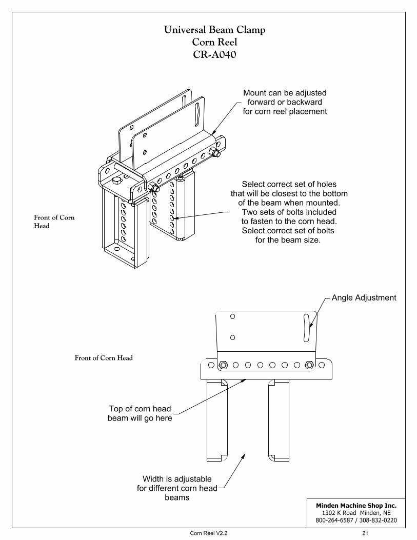
Universal Beam ClampCorn ReelCR-A040
Corn Reel Beam Mounts
Note: Universal Beam Clamp includes two different lengths ofbolts. Please select the correct one for the corn head that it is being mounted on.The universal mount will be placed on the top of the corn head beam and only two of the bolts will be used to mount the beam clamp. As these will be placed under the corn head beam and tigtened in place.
Corn Reel V2.2 14

Minden Machine Shop Inc.
1302 K Road Minden, NE
800-264-6587 / 308-832-0220
Case Narrower Beam ClampCR-A021
10 Series Corn Heads
Front of Corn Head
Front of Corn Head
Angle the Beam Arm Tube
from here
Guide Bolts
10
7
8
14
9
16
3
1
2
Corn Reel V2.2 15

Minden Machine Shop Inc.
1302 K Road Minden, NE
800-264-6587 / 308-832-0220
Geringhoff Pre-2012 Beam Mounts
11
1
2
14
3
16
4
7
8
15
13
16
13
5
8
Front of Corn Head
Front of Corn Head
Front of Corn Head
Front of Corn Head
Inner MountCR-A028
Outer MountCR-A029
Angle Adjustment
Holes for Guide Bolts
Corn Reel V2.2 16

Minden Machine Shop Inc.
1302 K Road Minden, NE
800-264-6587 / 308-832-0220
Geringhoff 2012 and Newer Beam MountsRound Tube
16
3
16
11
5
8
3
3
16
Inner MountCR-A030
12
11
16
10
7
8
Front of Corn Head
Front of Corn Head
Front of Corn Head
Front of Corn Head
Outer MountCR-A031
Corn Reel V2.2 17

Minden Machine Shop Inc.
1302 K Road Minden, NE
800-264-6587 / 308-832-0220
Geringhoff North Star Elite XLBeam Mount
13
5
16
10
11
16
Front of Corn Head
Front of Corn Head
Corn Reel V2.2 18

Minden Machine Shop Inc.
1302 K Road Minden, NE
800-264-6587 / 308-832-0220
Gleaner Beam MountCR-A022
11
7
8
9
3
4
Front of Corn Head
Front of Corn Head
Angle Adjustment
Use plate to account for
angle of corn head so
mount is flat.
Corn Reel V2.2 19

Minden Machine Shop Inc.
1302 K Road Minden, NE
800-264-6587 / 308-832-0220
Massey Beam MountCR-A024
11
7
8
11
3
4
Front of Corn Head
Front of Corn Head
Angle Adjustment
Corn Reel V2.2 20
Minden Machine Shop Inc.
1302 K Road Minden, NE
800-264-6587 / 308-832-0220
Universal Beam ClampCorn ReelCR-A040
Front of Corn Head
Front of CornHead
Angle Adjustment
Top of corn head
beam will go here
Width is adjustable
for different corn head
beams
Select correct set of holes
that will be closest to the bottom
of the beam when mounted.
Two sets of bolts included
to fasten to the corn head.
Select correct set of bolts
for the beam size.
Mount can be adjusted
forward or backward
for corn reel placement
Corn Reel V2.2 21

Torque Data for Standard Nuts, Bolts, and CapscrewsTighten all bolts to torques specified in chart unless otherwise noted. Check tightness of bolts periodically,
using bolt chart as guide. Replace hardware with some grade bolt.
Note: Unless otherwise specified, high-strength Grade 5 hex bolts are used throughout assembly of equipment.
Bolt Torque for Standard Bolts
Bolt Size A lb-ft (N.m) lb-ft (N.m) lb-ft (N.m)
1/4" 6 8 9 12 12 16
5/16" 10 13 18 25 25 35
3/8" 20 27 30 40 45 60
7/16" 30 40 50 70 80 110
1/2" 45 60 75 100 115 155
9/16" 70 95 115 155 165 220
5/8" 95 130 150 200 225 300
3/4" 165 225 290 390 400 540
7/8" 170 230 420 570 650 880
1" 225 300 630 850 970 1310
Bolt Torque for Metric Bolts
Bolt Size A lb-ft (N.m) lb-ft (N.m) lb-ft (N.m)
6 9 13 10 14 13 17
7 15 21 18 24 21 29
8 23 31 25 34 31 42
10 45 61 50 68 61 83
12 78 106 88 118 106 144
14 125 169 140 189 170 230
16 194 263 216 293 263 357
18 268 363 .. .. 364 493
20 378 513 .. .. 515 689
22 516 699 .. .. 702 952
24 654 886 .. .. 890 1206
Grade or Class value for bolts and capscrews are identified by their head markings.
Grade 2 Grade 5 Grade 8
Class 8.8 Class 9.8 Class 10.9
Torque figures indicated are valid for non-greased or non-oiled threads and heads unless otherwise specified. Therefore, do not grease or oil bolts or capscrews unless otherwise specified in this manual. When using locking elements, increase torque values by 5%.
Torque figures indicated are valid for non-greased or non-oiled threads and heads unless otherwise specified. Therefore, do not grease or oil bolts or capscrews unless otherwise specified in this manual. When using locking elements, increase torque values by 5%.
Corn Reel V2.2 22

Machine Measurements
Corn Reel V2.2 23

A
72
35
35
35 35
72
252536 36
69
ALTERNATE ALL BATS 90°
4 ROW 36" BASIC SPACINGFOR 38" AND 40" ADD CORRECT DISTANCES
GUARD MOUNT BRACKETTHIS LOCATION ONLY
KEYWAY CUTOUTTHIS SIDE
CHAIN GUARD SHOULD NOTRUB ON REEL BAT
22 1/8
6 1/8
Corn Reel V2.2 24

A
53 35 35 53
9090
21 21 303030 30GUARD MOUNT BRACKETTHIS LOCATION ONLY
CHAIN GUARD SHOULD NOTRUB ON REEL BAT
LH SHAFT HASKEYWAY CUTOUTMOTOR MUST BE ON LH SIDE
ALTERNATE ALL BATS 90°
CENTER COUPLER ONCENTER SNOUT6 ROW 30" BASIC SPACING
Corn Reel V2.2 25

A
31
58 56
2991
120 120
89
3329
30 2130 21 30
8 ROW 30" BASIC SPACING
GUARD MOUNT BRACKETTHIS LOCATION ONLY
CENTER COUPLER ONCENTER SNOUT
CHAIN GUARD SHOULD NOTRUB ON REEL BAT
LH SHAFT HASKEYWAY CUTOUTMOTOR MUST BE ON LH SIDE
ALTERNATE ALL BATS 90°
Corn Reel V2.2 26

A
LH SHAFT HASKEYWAY CUTOUTMOTOR MUST BE ON LH SIDE
CHAIN GUARD SHOULD NOTRUB ON REEL BAT
ALTERNATE ALL BATS 90°
CENTER COUPLER ONCENTER SNOUT8 ROW 38" BASIC SPACING
152 152
3774
39 113 113
37 74
39
25 25 383838
GUARD MOUNT BRACKETTHIS LOCATION ONLY
Corn Reel V2.2 27

A
132 1/8
10923
64 43 45 1/8 61 7/8
109 23 1/8
132 1/8
1722 17 2222
12 ROW 22" BASIC SPACING
CHAIN GUARD SHOULD NOTRUB ON REEL BAT
LH SHAFT HASKEYWAY CUTOUTMOTOR MUST BE ON LH SIDE
GUARD MOUNT BRACKETTHIS LOCATION ONLY
ALTERNATE ALL BATS 90°
CENTER COUPLER ONCENTER SNOUT
Corn Reel V2.2 28

D
180 180
298661598829
149 149
213030 21 30
CHAIN GUARD SHOULD NOTRUB ON REEL BAT
LH SHAFT HASKEYWAY CUTOUTMOTOR MUST BE ON LH SIDE
GUARD MOUNT BRACKETTHIS LOCATION ONLY
CENTER COUPLER ONCENTER SNOUT12 ROW 30" BASIC SPACING
ALTERNATE ALL BATS 90°
Corn Reel V2.2 29

A
22
67 1/8
131
65
131
CHAIN GUARD SHOULD NOTRUB ON REEL BAT
181 1/8181 1/8
16 ROW 22" BASIC SPACING
50 1/8 50 1/8
64 61 7/8
22 22
ALTERNATE ALL BATS 90°
LH SHAFT HASKEYWAY CUTOUTMOTOR MUST BE ON LH SIDE
17 17
GUARD MOUNT BRACKETTHIS LOCATION ONLY
CENTER COUPLER ONCENTER SNOUT
Corn Reel V2.2 30

A
180
5978 62 1/4 74 3/4
180
CHAIN GUARD SHOULD NOTRUB ON REEL BAT
16
16
20203 1/2
181
20 20
3 1/2
181
LH SHAFT HASKEYWAY CUTOUTMOTOR MUST BE ON LH SIDE
GUARD MOUNT BRACKETTHIS LOCATION ONLY
CENTER COUPLER ONCENTER SNOUT24 ROW 20" BASIC SPACING
ALTERNATE ALL BATS 90°
Corn Reel V2.2 31

Minden Machine Shop Inc
LIMITED WARRANTY Minden Machine Shop Inc warrants all products manufactured by it to be free of defect in material and
workmanship for a period of one (1) year from the date of purchase.
This Minden Machine Shop Inc. warranty does not cover:
1. Parts and accessories supplied by Minden Machine Shop Inc. but manufactured by others. Minden
Machine Shop Inc. will facilitate the other manufacturer warranty for the benefit of the purchaser but will
not be bound thereby (example: augers, motors, trailers, tanks, etc.).
2. Products that have been altered by anyone other than a Minden Machine Shop Inc. employee or are used by
the purchaser, for purposes other than what was intended at time of manufacture or used in excess of the
“built specifications”.
3. Products that are custom manufactured by Minden Machine Shop Inc. utilizing the purchaser’s design
which deviates from Minden Machine Shop Inc. normal production line manufactured or customized
features of the products.
4. Malfunctions or damages to the product from misuse, negligence, customer alteration, accidents or product
abuse due to incoming material or poor material flow ability or lack of required performance or required
maintenance (e.g., poor material flow ability caused by incoming wet fertilizer or hot soybean meal, etc).
5. Loss of time, inconvenience, loss of material, down time or any other consequential damage.
6. Product use for a function that is different than designed intent (e.g., storing soybean meal in grain bin,
unacceptable material in the bin such as hot bean meal when product originally designed for other
application, etc).
7. Minden Machine Shop Inc is not responsible for any equipment that this product is attached to or mounted
on.
To activate this warranty, the purchaser must make contact in writing with Minden Machine Shop Inc. with in one
(1) year of date of purchase. After contact, Minden Machine Shop Inc. has the right to determine the cause and
qualify the legitimacy of the claim. Minden Machine Shop Inc., upon acceptance of a warranty claim, shall have a
reasonable time to plan any repair or replacement and may affect repair or replacement out of its factory or through
contract with a local repair service. If a purchaser after warranty notice is made, chooses to make the repair itself,
Minden Machine Shop Inc. must approve any expenses before they are incurred to be responsible for customer
reimbursement. Minden Machine Shop Inc. shall be liable on a warranty claim for repair or replacement of any
defective products and this is the purchaser’s sole and exclusive remedy. Minden Machine Shop Inc. will not be
liable for any other or further remedy including claims for personal injury, property damage or consequential
damage. The law of the Sate of Nebraska shall govern and any such claim and any issues with regard to the same
shall be resolved in the Nebraska District Court for the county of Kearney.
RETURN OF MERCHANDISE Merchandise may not be returned without written approval from the factory. All returns must have a return
authorization number. Obtain this number before the return and show it on all return items. A 15% restocking
charge is made on merchandise returned. Returned merchandise must be shipped pre-paid.
RECEIVING MERCHANDISE AND FILING CLAIMS When receiving merchandise it is important to check both the number of parts and their description with packing
slip. The consignee must make all claims for freight damage or shortage within 10 days from the date of delivery.
When the material leaves the factory it becomes the property of the consignee. It is the responsibility of the
consignee to file a claim on any possible damage or loss. Please list your preferred routing on purchase orders.
MODIFICATIONS It is the policy of Minden Machine Shop Inc. to improve its products whenever possible and practical to do so. We
reserve the right to make changes, improvements and modifications at any time without incurring the obligation to
make such changes, improvements and modifications on any equipment sold previously.
Corn Reel V2.2 32

WARRANTY REGISTRATION
To register equipment, or file a claim, copy and paste the words on this page into an email
or word document, fill out the appropriate information completely, and email it to
[email protected] with the subject as EQUIPMENT WARRANTY, or fill it out
and fax it to 308-832-1340.
Dealer Information: Not Applicable, check here: [ ]
Dealer Name:
Address:
City:
State:
Zip Code:
Phone #:
Email:
End User Information:
Purchaser:
Address:
City:
State:
Zip Code:
Phone #:
Email:
Equipment:
Serial #:
Date Of Purchase: / /
Corn Reel V2.2 33