section no. series 685i -...
TRANSCRIPT
The Company, L.L.C. • Oklahoma City, Oklahoma • Tel: (405) 672-6660 • Fax: (405) 672-6661 • wellmarkco.com
Series
©2011 The WellMark Company, L.L.C. • Litho USA • WM685I-8/08 • All registered trademarks are the property of their respective owners. 1
685ISection No. 1.1
685I Visual Liquid Level Indicator for Atmospheric Vessels
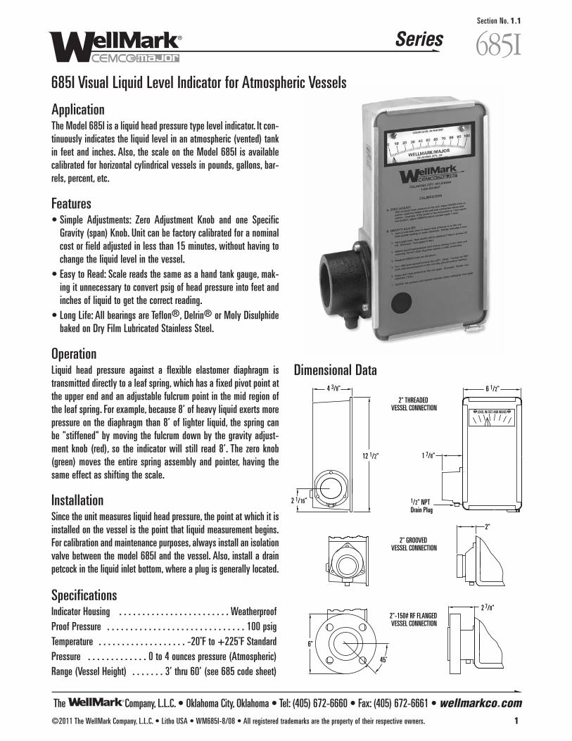
ApplicationThe Model 685I is a liquid head pressure type level indicator. It con-tinuously indicates the liquid level in an atmospheric (vented) tankin feet and inches. Also, the scale on the Model 685I is availablecalibrated for horizontal cylindrical vessels in pounds, gallons, bar-rels, percent, etc.
Features• Simple Adjustments: Zero Adjustment Knob and one Specific
Gravity (span) Knob. Unit can be factory calibrated for a nominalcost or field adjusted in less than 15 minutes, without having tochange the liquid level in the vessel.
• Easy to Read: Scale reads the same as a hand tank gauge, mak-ing it unnecessary to convert psig of head pressure into feet andinches of liquid to get the correct reading.
• Long Life: All bearings are Teflon®, Delrin® or Moly Disulphidebaked on Dry Film Lubricated Stainless Steel.
Operation Liquid head pressure against a flexible elastomer diaphragm istransmitted directly to a leaf spring, which has a fixed pivot point atthe upper end and an adjustable fulcrum point in the mid region ofthe leaf spring. For example, because 8’ of heavy liquid exerts morepressure on the diaphragm than 8’ of lighter liquid, the spring canbe "stiffened" by moving the fulcrum down by the gravity adjust-ment knob (red), so the indicator will still read 8’. The zero knob(green) moves the entire spring assembly and pointer, having thesame effect as shifting the scale.
InstallationSince the unit measures liquid head pressure, the point at which it isinstalled on the vessel is the point that liquid measurement begins.For calibration and maintenance purposes, always install an isolationvalve between the model 685I and the vessel. Also, install a drainpetcock in the liquid inlet bottom, where a plug is generally located.
SpecificationsIndicator Housing . . . . . . . . . . . . . . . . . . . . . . . . WeatherproofProof Pressure . . . . . . . . . . . . . . . . . . . . . . . . . . . . . . 100 psigTemperature . . . . . . . . . . . . . . . . . . . -20˚F to +225˚F StandardPressure . . . . . . . . . . . . . 0 to 4 ounces pressure (Atmospheric)Range (Vessel Height) . . . . . . . 3’ thru 60’ (see 685 code sheet)
Dimensional Data
45˚
6"
2 7/8"
2"
12 1/2"
2 1/16"
4 3/8"
2" GROOVED VESSEL CONNECTION
2"-150# RF FLANGED VESSEL CONNECTION
2" THREADED VESSEL CONNECTION
1 7/8"
6 1/2"
1/2" NPTDrain Plug
The Company, L.L.C. • Oklahoma City, Oklahoma • Tel: (405) 672-6660 • Fax: (405) 672-6661 • wellmarkco.com
Series
2 ©2011 The WellMark Company, L.L.C. • Litho USA • WM685I-8/08 • All registered trademarks are the property of their respective owners.
685ISection No. 1.1
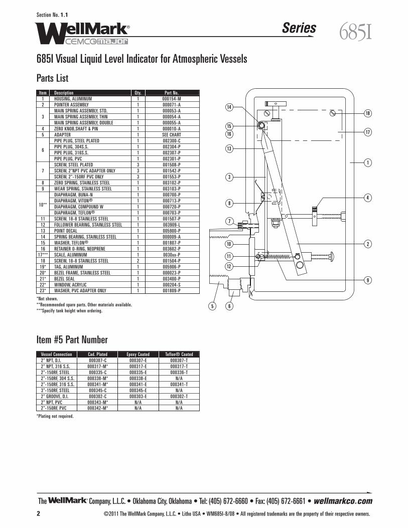
Parts List
Item #5 Part NumberVessel Connection Cad. Plated Epoxy Coated Teflon® Coated2" NPT, D.I. 000307-C 000307-E 000307-T 2" NPT, 316 S.S. 000317-M* 000317-E 000317-T2"-150RF, STEEL 000335-C 000335-E 000336-T2"-150RF, 304 S.S. 000338-M* 000338-E N/A2"-150RF, 316 S.S. 000341-M* 000341-E 000341-T3"-150RF, STEEL 000345-C 000345-E N/A2" GROOVE, D.I. 000302-C 000303-E 000302-T2" NPT, PVC 000343-M* N/A N/A2"-150RF, PVC 000342-M* N/A N/A
*Plating not required.
685I Visual Liquid Level Indicator for Atmospheric Vessels
17
18
1
4
2
9
14
15
16
13
3
8
7
10
11
12
5 6
Item Description Qty. Part No.1 HOUSING, ALUMINUM 1 000154-M2 POINTER ASSEMBLY 1 000071-A
MAIN SPRING ASSEMBLY, STD. 1 000053-A3 MAIN SPRING ASSEMBLY, THIN 1 000054-A
MAIN SPRING ASSEMBLY, DOUBLE 1 000055-A4 ZERO KNOB,SHAFT & PIN 1 000010-A5 ADAPTER 1 SEE CHART
PIPE PLUG, STEEL PLATED 1 002300-C
6PIPE PLUG, 304S.S. 1 002304-PPIPE PLUG, 316S.S. 1 002307-PPIPE PLUG, PVC 1 002301-PSCREW, STEEL PLATED 3 001508-P
7 SCREW, 2"NPT PVC ADAPTER ONLY 3 001542-PSCREW, 2"-150RF PVC ONLY 3 001553-P
8 ZERO SPRING, STAINLESS STEEL 1 003102-P9 WEAR SPRING, STAINLESS STEEL 1 003103-P
DIAPHRAGM, BUNA-N 1 000700-P
10**DIAPHRAGM, VITON® 1 000713-PDIAPHRAGM, COMPOUND W 1 000720-PDIAPHRAGM, TEFLON® 1 000703-P
11 SCREW, 18-8 STAINLESS STEEL 1 001507-P12 FOLLOWER BEARING, STAINLESS STEEL 1 003909-L13 POINT DECAL 1 005900-P14 SPRING BEARING, STAINLESS STEEL 1 000009-A15 WASHER, TEFLON® 1 001807-P16 RETAINER O-RING, NEOPRENE 1 003602-P
17*** SCALE, ALUMINUM 1 0030xx-P18 SCREW, 18-8 STAINLESS STEEL 2 001504-P19* TAG, ALUMINUM 1 005906-P20* BEZEL FRAME, STAINLESS STEEL 1 000023-P21* BEZEL SEAL 1 003400-P22* WINDOW, ACRYLIC 1 000204-S23* WASHER, PVC ADAPTER ONLY 1 001809-P
*Not shown.**Recommended spare parts. Other materials available.***Specify tank height when ordering.
The Company, L.L.C. • Oklahoma City, Oklahoma • Tel: (405) 672-6660 • Fax: (405) 672-6661 • wellmarkco.com
Series
©2011 The WellMark Company, L.L.C. • Litho USA • WM685S-12/08 • All registered trademarks are the property of their respective owners. 3
685SSection No. 1.2
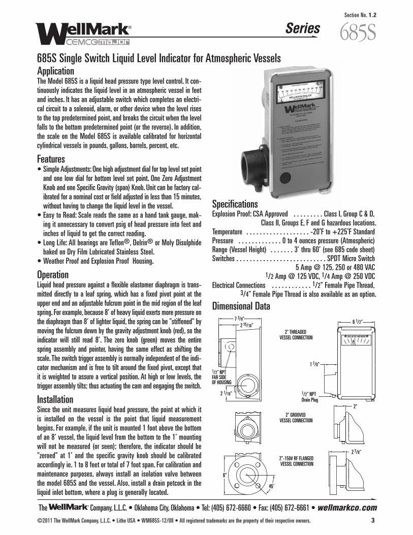
685S Single Switch Liquid Level Indicator for Atmospheric VesselsApplicationThe Model 685S is a liquid head pressure type level control. It con-tinuously indicates the liquid level in an atmospheric vessel in feetand inches. It has an adjustable switch which completes an electri-cal circuit to a solenoid, alarm, or other device when the level risesto the top predetermined point, and breaks the circuit when the levelfalls to the bottom predetermined point (or the reverse). In addition,the scale on the Model 685S is available calibrated for horizontalcylindrical vessels in pounds, gallons, barrels, percent, etc.
Features• Simple Adjustments: One high adjustment dial for top level set point
and one low dial for bottom level set point. One Zero AdjustmentKnob and one Specific Gravity (span) Knob. Unit can be factory cal-ibrated for a nominal cost or field adjusted in less than 15 minutes,without having to change the liquid level in the vessel.
• Easy to Read: Scale reads the same as a hand tank gauge, mak-ing it unnecessary to convert psig of head pressure into feet andinches of liquid to get the correct reading.
• Long Life: All bearings are Teflon®, Delrin® or Moly Disulphidebaked on Dry Film Lubricated Stainless Steel.
• Weather Proof and Explosion Proof Housing.
Operation Liquid head pressure against a flexible elastomer diaphragm is trans-mitted directly to a leaf spring, which has a fixed pivot point at theupper end and an adjustable fulcrum point in the mid region of the leafspring. For example, because 8’ of heavy liquid exerts more pressure onthe diaphragm than 8’ of lighter liquid, the spring can be "stiffened" bymoving the fulcrum down by the gravity adjustment knob (red), so theindicator will still read 8’. The zero knob (green) moves the entirespring assembly and pointer, having the same effect as shifting thescale. The switch trigger assembly is normally independent of the indi-cator mechanism and is free to tilt around the fixed pivot, except thatit is weighted to assure a vertical position. At high or low levels, thetrigger assembly tilts; thus actuating the cam and engaging the switch.
InstallationSince the unit measures liquid head pressure, the point at which itis installed on the vessel is the point that liquid measurementbegins. For example, if the unit is mounted 1 foot above the bottomof an 8’ vessel, the liquid level from the bottom to the 1’ mountingwill not be measured (or seen); therefore, the indicator should be"zeroed" at 1’ and the specific gravity knob should be calibratedaccordingly ie. 1 to 8 feet or total of 7 foot span. For calibration andmaintenance purposes, always install an isolation valve betweenthe model 685S and the vessel. Also, install a drain petcock in theliquid inlet bottom, where a plug is generally located.
SpecificationsExplosion Proof: CSA Approved . . . . . . . . . Class I, Group C & D,
Class II, Groups E, F and G hazardous locations.Temperature . . . . . . . . . . . . . . . . . . . -20˚F to +225˚F StandardPressure . . . . . . . . . . . . . 0 to 4 ounces pressure (Atmospheric)Range (Vessel Height) . . . . . . . 3’ thru 60’ (see 685 code sheet)Switches . . . . . . . . . . . . . . . . . . . . . . . . . . . SPDT Micro Switch
5 Amp @ 125, 250 or 480 VAC1/2 Amp @ 125 VDC, 1/4 Amp @ 250 VDC
Electrical Connections . . . . . . . . . . . . 1/2" Female Pipe Thread, 3/4" Female Pipe Thread is also available as an option.
Dimensional Data
45˚
6"
2 7/8"
2"
2 1/16"
7 3/8"
1/2" NPTFAR SIDE OF HOUSING
2" GROOVED VESSEL CONNECTION
2"-150# RF FLANGED VESSEL CONNECTION
2 15/16"2" THREADED
VESSEL CONNECTION
1 7/8"
6 1/2"
1/2" NPTDrain Plug
The Company, L.L.C. • Oklahoma City, Oklahoma • Tel: (405) 672-6660 • Fax: (405) 672-6661 • wellmarkco.com
Series
4 ©2011 The WellMark Company, L.L.C. • Litho USA • WM685S-12/08 • All registered trademarks are the property of their respective owners.
685SSection No. 1.2
685S Single Switch Liquid Level Indicator for Atmospheric Vessels
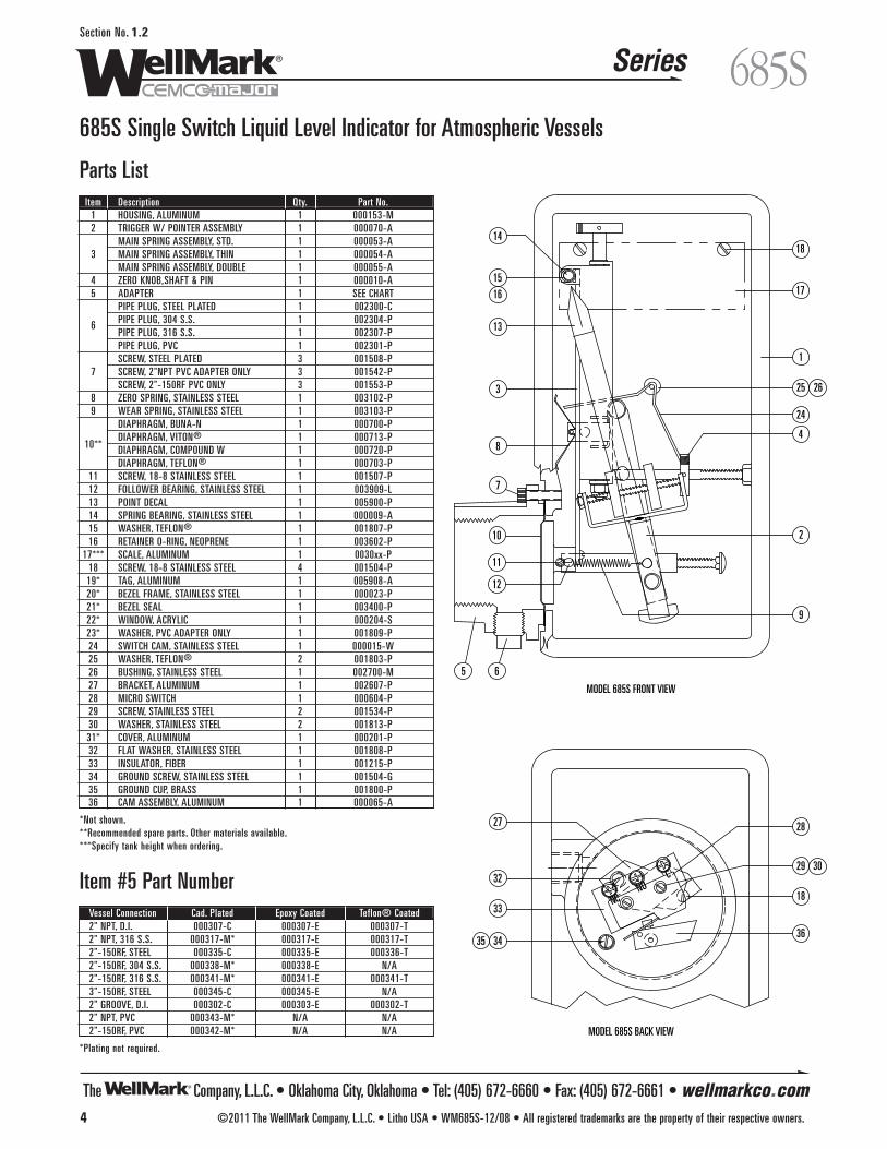
Parts List
Item #5 Part NumberVessel Connection Cad. Plated Epoxy Coated Teflon® Coated2" NPT, D.I. 000307-C 000307-E 000307-T 2" NPT, 316 S.S. 000317-M* 000317-E 000317-T2"-150RF, STEEL 000335-C 000335-E 000336-T2"-150RF, 304 S.S. 000338-M* 000338-E N/A2"-150RF, 316 S.S. 000341-M* 000341-E 000341-T3"-150RF, STEEL 000345-C 000345-E N/A2" GROOVE, D.I. 000302-C 000303-E 000302-T2" NPT, PVC 000343-M* N/A N/A2"-150RF, PVC 000342-M* N/A N/A
*Plating not required.
MODEL 685S BACK VIEW
NCNO
C
9
2
4
1
18
17
8
3
13
16
15
14
65
12
11
10
7
25 26
24
MODEL 685S FRONT VIEW
27 28
29 3032
33
343536
18
Item Description Qty. Part No.1 HOUSING, ALUMINUM 1 000153-M2 TRIGGER W/ POINTER ASSEMBLY 1 000070-A
MAIN SPRING ASSEMBLY, STD. 1 000053-A3 MAIN SPRING ASSEMBLY, THIN 1 000054-A
MAIN SPRING ASSEMBLY, DOUBLE 1 000055-A4 ZERO KNOB,SHAFT & PIN 1 000010-A5 ADAPTER 1 SEE CHART
PIPE PLUG, STEEL PLATED 1 002300-C
6 PIPE PLUG, 304 S.S. 1 002304-PPIPE PLUG, 316 S.S. 1 002307-PPIPE PLUG, PVC 1 002301-PSCREW, STEEL PLATED 3 001508-P
7 SCREW, 2"NPT PVC ADAPTER ONLY 3 001542-PSCREW, 2"-150RF PVC ONLY 3 001553-P
8 ZERO SPRING, STAINLESS STEEL 1 003102-P9 WEAR SPRING, STAINLESS STEEL 1 003103-P
DIAPHRAGM, BUNA-N 1 000700-P
10**DIAPHRAGM, VITON® 1 000713-PDIAPHRAGM, COMPOUND W 1 000720-PDIAPHRAGM, TEFLON® 1 000703-P
11 SCREW, 18-8 STAINLESS STEEL 1 001507-P12 FOLLOWER BEARING, STAINLESS STEEL 1 003909-L13 POINT DECAL 1 005900-P14 SPRING BEARING, STAINLESS STEEL 1 000009-A15 WASHER, TEFLON® 1 001807-P16 RETAINER O-RING, NEOPRENE 1 003602-P
17*** SCALE, ALUMINUM 1 0030xx-P18 SCREW, 18-8 STAINLESS STEEL 4 001504-P19* TAG, ALUMINUM 1 005908-A20* BEZEL FRAME, STAINLESS STEEL 1 000023-P21* BEZEL SEAL 1 003400-P22* WINDOW, ACRYLIC 1 000204-S23* WASHER, PVC ADAPTER ONLY 1 001809-P24 SWITCH CAM, STAINLESS STEEL 1 000015-W25 WASHER, TEFLON® 2 001803-P26 BUSHING, STAINLESS STEEL 1 002700-M27 BRACKET, ALUMINUM 1 002607-P28 MICRO SWITCH 1 000604-P29 SCREW, STAINLESS STEEL 2 001534-P30 WASHER, STAINLESS STEEL 2 001813-P31* COVER, ALUMINUM 1 000201-P32 FLAT WASHER, STAINLESS STEEL 1 001808-P33 INSULATOR, FIBER 1 001215-P34 GROUND SCREW, STAINLESS STEEL 1 001504-G35 GROUND CUP, BRASS 1 001800-P36 CAM ASSEMBLY, ALUMINUM 1 000065-A
*Not shown.**Recommended spare parts. Other materials available.***Specify tank height when ordering.

The Company, L.L.C. • Oklahoma City, Oklahoma • Tel: (405) 672-6660 • Fax: (405) 672-6661 • wellmarkco.com
Series
©2011 The WellMark Company, L.L.C. • Litho USA • WM685SMultiswitch-12/08 • All registered trademarks are the property of their respective owners. 5
685SMultiswitchSection No. 1.3
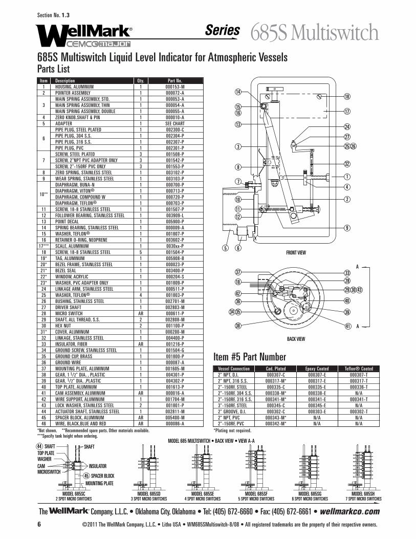
685S Multiswitch Liquid Level Indicator for Atmospheric VesselsApplicationThe Model 685S Multiswitch is a liquid head pressure type control,which continuously indicates the liquid level and supplies on and offsignal as adjusted. Each switch may be set at different set points tocontrol a separate device, such as an auxiliary or motor controlrelay, alarms, etc.
Features• Easy to read: Scale reads the same as a hand tank gauge, mak-
ing it unnecessary to convert psig of head pressure into feet andinches of liquid to get the correct reading.
• Special Scales: Gallons, Pounds, Percent, etc. is available.• Long Life: All bearings are Teflon®, Delrin® or Moly Disulphide
baked on Dry Film Lubricated Stainless Steel.• Weather Proof and Explosion Proof Housing.
Operation Liquid head pressure against a flexible elastomer diaphragm istransmitted directly to a leaf spring, which has a fixed pivot point atthe upper end and an adjustable fulcrum point in the mid region ofthe leaf spring. For example, because 8’ of heavy liquid exerts morepressure on the diaphragm than 8’ of lighter liquid, the spring canbe "stiffened" by moving the fulcrum down by the gravity adjust-ment knob (red), so the unit will still read 8’. The zero knob (green)moves the entire spring assembly and pointer, having the sameeffect as shifting the scale. The movement of the pointer rotates alinkage connected to a shaft extending into the explosion proofhousing where the switches are located. The shaft drives a gear,which is connected to cams that actuate each switch individually.
InstallationSince the unit measures liquid head pressure, the point at which it isinstalled on the vessel is the point that liquid measurement begins. Forcalibration and maintenance purposes always install an isolation valvebetween the Model 685 and the vessel. Also, install a drain petcock inthe liquid inlet bottom, where a plug is generally located.
SpecificationsExplosion Proof: CSA Approved: . . . . . . . . . Class I, Group C & D
Class II, Groups E, F and G hazardous locations.Temperature . . . . . . . . . . . . . . . . . . . -20˚F to +225˚F StandardPressure . . . . . . . . . . . . . 0 to 4 ounces pressure (Atmospheric)Range (Vessel Height) . . . . . . 3’ thru 60’ (see 685 code sheet).Electrical Switches . . . . . . . . . . . . . . . . . . . SPDT Micro Switch
11 Amp @ 130 or 250 VAC, 1/2 Amp @ 125 VDC1/4 Amp @ 250 VDC, 4 Amp @ 125 VAC Induction
Electrical Connections . . . . . . . . . . . . 1/2" Female Pipe Thread, 3/4" Female Pipe Thread (Optional)
Dimensional Data
45˚
6"
2 7/8"
2"
2" GROOVED VESSEL CONNECTION
2"-150# RF FLANGED VESSEL CONNECTION
2" THREADED VESSEL CONNECTION
1 7/8"
6 1/2"
1/2" NPTDrain Plug
2 1/16"
11 11/16"7 5/16"
1/2" NPTElectrical Connection(FAR SIDE OF HOUSING)
The Company, L.L.C. • Oklahoma City, Oklahoma • Tel: (405) 672-6660 • Fax: (405) 672-6661 • wellmarkco.com
Series
BACK VIEW
A
A
9
2
4
1
18
17
8
3
13
1615
14
65
12
11
10
7
25 26
24
27
32
34 35
36
29 30
28
3337
18
38
39
40
41
4243
FRONT VIEW
MODEL 685SE4 SPDT MICRO SWITCHES
MODEL 685SF5 SPDT MICRO SWITCHES
MODEL 685SG6 SPDT MICRO SWITCHES
MODEL 685SH 7 SPDT MICRO SWITCHES
MODEL 685SD3 SPDT MICRO SWITCHES
MODEL 685 MULTISWITCH • BACK VIEW • VIEW A-A
MODEL 685SC2 SPDT MICRO SWITCHES
TOP PLATE
MOUNTING PLATE
SHAFT
45
44
WASHERCAMMICROSWITCH
SPACER BLOCK
INSULATOR
SHAFT
6 ©2011 The WellMark Company, L.L.C. • Litho USA • WM685SMultiswitch-8/08 • All registered trademarks are the property of their respective owners.
685SMultiswitchSection No. 1.3
685S Multiswitch Liquid Level Indicator for Atmospheric VesselsParts List
Item #5 Part NumberVessel Connection Cad. Plated Epoxy Coated Teflon® Coated2" NPT, D.I. 000307-C 000307-E 000307-T 2" NPT, 316 S.S. 000317-M* 000317-E 000317-T2"-150RF, STEEL 000335-C 000335-E 000336-T2"-150RF, 304 S.S. 000338-M* 000338-E N/A2"-150RF, 316 S.S. 000341-M* 000341-E 000341-T3"-150RF, STEEL 000345-C 000345-E N/A2" GROOVE, D.I. 000302-C 000303-E 000302-T2" NPT, PVC 000343-M* N/A N/A2"-150RF, PVC 000342-M* N/A N/A
*Plating not required.
Item Description Qty. Part No.1 HOUSING, ALUMINUM 1 000153-M2 POINTER ASSEMBLY 1 000072-A
MAIN SPRING ASSEMBLY, STD. 1 000053-A3 MAIN SPRING ASSEMBLY, THIN 1 000054-A
MAIN SPRING ASSEMBLY, DOUBLE 1 000055-A4 ZERO KNOB,SHAFT & PIN 1 000010-A5 ADAPTER 1 SEE CHART
PIPE PLUG, STEEL PLATED 1 002300-C
6 PIPE PLUG, 304 S.S. 1 002304-PPIPE PLUG, 316 S.S. 1 002307-PPIPE PLUG, PVC 1 002301-PSCREW, STEEL PLATED 3 001508-P
7 SCREW, 2"NPT PVC ADAPTER ONLY 3 001542-PSCREW, 2"-150RF PVC ONLY 3 001553-P
8 ZERO SPRING, STAINLESS STEEL 1 003102-P9 WEAR SPRING, STAINLESS STEEL 1 003103-P
DIAPHRAGM, BUNA-N 1 000700-P
10**DIAPHRAGM, VITON® 1 000713-PDIAPHRAGM, COMPOUND W 1 000720-PDIAPHRAGM, TEFLON® 1 000703-P
11 SCREW, 18-8 STAINLESS STEEL 1 001507-P12 FOLLOWER BEARING, STAINLESS STEEL 1 003909-L13 POINT DECAL 1 005900-P14 SPRING BEARING, STAINLESS STEEL 1 000009-A15 WASHER, TEFLON® 1 001807-P16 RETAINER O-RING, NEOPRENE 1 003602-P
17*** SCALE, ALUMINUM 1 0030xx-P18 SCREW, 18-8 STAINLESS STEEL 5 001504-P19* TAG, ALUMINUM 1 005908-B20* BEZEL FRAME, STAINLESS STEEL 1 000023-P21* BEZEL SEAL 1 003400-P22* WINDOW, ACRYLIC 1 000204-S23* WASHER, PVC ADAPTER ONLY 1 001809-P24 LINKAGE ARM, STAINLESS STEEL 1 000511-P25 WASHER, TEFLON® 4 001803-P26 BUSHING, STAINLESS STEEL 1 002701-M27 DRIVER SHAFT 1 002803-M28 MICRO SWITCH AR 000611-P29 SHAFT, ALL THREAD, S.S. 2 002808-M30 HEX NUT 2 001100-P31* COVER, ALUMINUM 1 000200-M32 LINKAGE, STAINLESS STEEL 1 004400-P33 INSULATOR, FIBER AR 001216-P34 GROUND SCREW, STAINLESS STEEL 1 001504-G35 GROUND CUP, BRASS 1 001800-P36 GROUND WIRE 1 000087-A37 MOUNTING PLATE, ALUMINUM 1 001605-M38 GEAR, 1 1/2" DIA. , PLASTIC 1 004301-P39 GEAR, 1/2" DIA. ,PLASTIC 1 004302-P40 TOP PLATE, ALUMINUM 1 001613-P41 CAM ASSEMBLY, ALUMINUM AR 000016-A42 WIRE SUPPORT, ALUMINUM 1 001704-M43 LOCK WASHER, STAINLESS STEEL 2 001801-P44 ACTUATOR SHAFT, STAINLESS STEEL 1 002811-M45 SPACER BLOCK, ALUMINUM AR 005400-M46 WIRE, BLACK,BLUE AND RED AR 000086-A
*Not shown. **Recommended spare parts. Other materials available.***Specify tank height when ordering.

The Company, L.L.C. • Oklahoma City, Oklahoma • Tel: (405) 672-6660 • Fax: (405) 672-6661 • wellmarkco.com
Series
2 1/16"
11 11/16"7 5/16"
1/2" NPTElectrical Connection(FAR SIDE OF HOUSING)
45˚
6"
2 7/8"
2"
2" GROOVED VESSEL CONNECTION
2"-150# RF FLANGED VESSEL CONNECTION
2" THREADED VESSEL CONNECTION
1 7/8"
6 1/2"
1/2" NPTDrain Plug
©2011 The WellMark Company, L.L.C. • Litho USA • WM685E-12/08 • All registered trademarks are the property of their respective owners. 7
685ESection No. 1.4
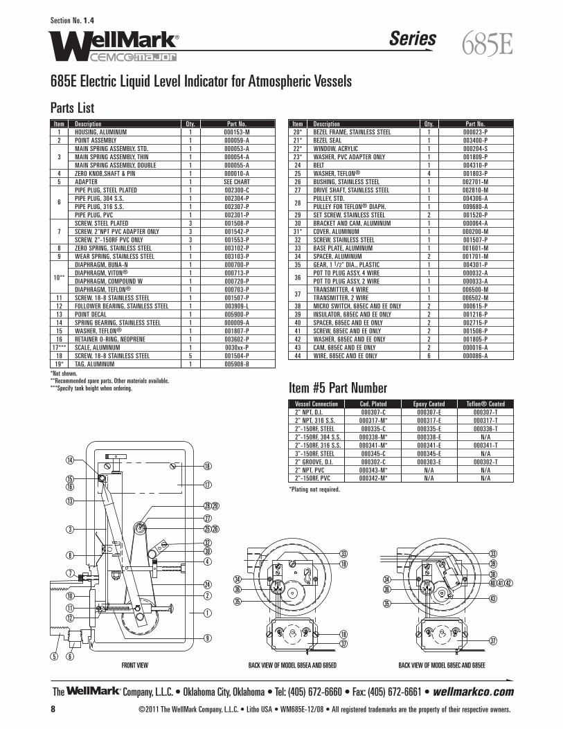
685E Electric Liquid Level Indicator for Atmospheric VesselsApplicationThe Model 685E Liquid Level Transmitter is an electro-mechanicallevel control device, which accomplishes three (3) main functions.These are remote indication, local liquid level indication, and hi-lowadjustable switch outputs. The unit continuously indicates the liquidlevel and transmits a proportional signal.
Features• Complementary Adjustments: Zero and Span adjustments at transmitter.• Easy to Read: Scale reads the same as a hand tank gauge, mak-
ing it unnecessary to convert psig of head pressure into feet andinches of liquid to get the correct reading.
• Special Scales: Gallons, Pounds, Percent, etc. is available.• Long Life: All bearings are Teflon®, Delrin® or Moly Disulphide
baked on Dry Film Lubricated Stainless Steel.• Weather Proof and Explosion Proof Housing.
Operation Liquid head pressure against a flexible elastomer diaphragm istransmitted directly to a leaf spring, which has a fixed pivot point atthe upper end and an adjustable fulcrum point in the mid region ofthe leaf spring. For example, because 8’ of heavy liquid exerts morepressure on the diaphragm than 8’ of lighter liquid, the spring can be"stiffened" by moving the fulcrum down by the gravity adjustmentknob (red), so the transmitter will still read 8’. The zero knob (green)moves the entire spring assembly and pointer, having the sameeffect as shifting the scale. The movement of the pointer rotates ashaft extending into the explosion proof housing where the electron-ic transmitter and switches are located. The shaft drives a poten-tiometer, thereby giving a continuous signal to the plug-in amplifier.The proportional signal is then transmitted to the remote indicatingdevice in proportion to the liquid level which exists in the tank.
InstallationSince the unit measures liquid head pressure, the point at which it isinstalled on the vessel is the point that liquid measurement begins.For calibration and maintenance purposes, always install an isolationvalve between the model 685E and the vessel. Also, install a drainpetcock in the liquid inlet bottom, where a plug is generally located.
SpecificationsExplosion Proof: CSA Approved . . . . . . . . . . Class I, Group C & D,
Class II, Groups E, F and G hazardous locations.Temperature . . . . . . . . . . . . . . . . . . . -20˚F to +225˚F StandardPressure . . . . . . . . . . . . . . 0 to 4 ounces pressure (Atmospheric)Range (Vessel Height) . . . . . . . 3’ thru 60’ (see 685 code sheet)Transmitter Output . . . . . Four (4) Wires or Two (2) Wire System. SupplyVoltage (at transmitter) . . .120VAC, 60 Cycle, 1 phase (4-Wire)
24 VDC (2-Wire)
Electrical Switches . . . . . . . . . . . . . . . . . . . SPDT Micro Switch11 Amp @ 130 or 250 VAC, 1/2 Amp @ 125 VDC
1/4 Amp @ 250 VDC, 4 Amp @ 125 VAC InductionElectrical Connections . . . . . . . . . . . . 1/2" Female Pipe Thread,
3/4" Female PipeThread is also available as an option.
Dimensional Data
The Company, L.L.C. • Oklahoma City, Oklahoma • Tel: (405) 672-6660 • Fax: (405) 672-6661 • wellmarkco.com
Series
8 ©2011 The WellMark Company, L.L.C. • Litho USA • WM685E-12/08 • All registered trademarks are the property of their respective owners.
685ESection No. 1.4
685E Electric Liquid Level Indicator for Atmospheric Vessels
Parts List
Item #5 Part NumberVessel Connection Cad. Plated Epoxy Coated Teflon® Coated2" NPT, D.I. 000307-C 000307-E 000307-T 2" NPT, 316 S.S. 000317-M* 000317-E 000317-T2"-150RF, STEEL 000335-C 000335-E 000336-T2"-150RF, 304 S.S. 000338-M* 000338-E N/A2"-150RF, 316 S.S. 000341-M* 000341-E 000341-T3"-150RF, STEEL 000345-C 000345-E N/A2" GROOVE, D.I. 000302-C 000303-E 000302-T2" NPT, PVC 000343-M* N/A N/A2"-150RF, PVC 000342-M* N/A N/A
*Plating not required.
FRONT VIEW
9
2
4
1
18
17
8
3
13
1615
14
65
1211
10
7
25 26
24
27
28 29
3230
13 2POT
BACK VIEW OF MODEL 685EA AND 685ED
13 2POT
3318
34
35
36
3718
BACK VIEW OF MODEL 685EC AND 685EE
37
36
35
34
33
38
39
40 41 42
43
Item Description Qty. Part No.1 HOUSING, ALUMINUM 1 000153-M2 POINT ASSEMBLY 1 000059-A
MAIN SPRING ASSEMBLY, STD. 1 000053-A3 MAIN SPRING ASSEMBLY, THIN 1 000054-A
MAIN SPRING ASSEMBLY, DOUBLE 1 000055-A4 ZERO KNOB,SHAFT & PIN 1 000010-A5 ADAPTER 1 SEE CHART
PIPE PLUG, STEEL PLATED 1 002300-C
6 PIPE PLUG, 304 S.S. 1 002304-PPIPE PLUG, 316 S.S. 1 002307-PPIPE PLUG, PVC 1 002301-PSCREW, STEEL PLATED 3 001508-P
7 SCREW, 2"NPT PVC ADAPTER ONLY 3 001542-PSCREW, 2"-150RF PVC ONLY 3 001553-P
8 ZERO SPRING, STAINLESS STEEL 1 003102-P9 WEAR SPRING, STAINLESS STEEL 1 003103-P
DIAPHRAGM, BUNA-N 1 000700-P
10**DIAPHRAGM, VITON® 1 000713-PDIAPHRAGM, COMPOUND W 1 000720-PDIAPHRAGM, TEFLON® 1 000703-P
11 SCREW, 18-8 STAINLESS STEEL 1 001507-P12 FOLLOWER BEARING, STAINLESS STEEL 1 003909-L13 POINT DECAL 1 005900-P14 SPRING BEARING, STAINLESS STEEL 1 000009-A15 WASHER, TEFLON® 1 001807-P16 RETAINER O-RING, NEOPRENE 1 003602-P
17*** SCALE, ALUMINUM 1 0030xx-P18 SCREW, 18-8 STAINLESS STEEL 5 001504-P19* TAG, ALUMINUM 1 005908-B
*Not shown.**Recommended spare parts. Other materials available.***Specify tank height when ordering.
Item Description Qty. Part No.20* BEZEL FRAME, STAINLESS STEEL 1 000023-P21* BEZEL SEAL 1 003400-P22* WINDOW, ACRYLIC 1 000204-S23* WASHER, PVC ADAPTER ONLY 1 001809-P24 BELT 1 004310-P25 WASHER, TEFLON® 4 001803-P26 BUSHING, STAINLESS STEEL 1 002701-M27 DRIVE SHAFT, STAINLESS STEEL 1 002810-M
28PULLEY, STD. 1 004306-APULLEY FOR TEFLON® DIAPH. 1 009680-A
29 SET SCREW, STAINLESS STEEL 2 001520-P30 BRACKET AND CAM, ALUMINUM 1 000064-A31* COVER, ALUMINUM 1 000200-M32 SCREW, STAINLESS STEEL 1 001507-P33 BASE PLATE, ALUMINUM 1 001601-M34 SPACER, ALUMINUM 2 001701-M35 GEAR, 1 1/2" DIA., PLASTIC 1 004301-P
36POT TO PLUG ASSY, 4 WIRE 1 000032-APOT TO PLUG ASSY, 2 WIRE 1 000033-A
37TRANSMITTER, 4 WIRE 1 006500-MTRANSMITTER, 2 WIRE 1 006502-M
38 MICRO SWITCH, 685EC AND EE ONLY 2 000615-P39 INSULATOR, 685EC AND EE ONLY 2 001216-P40 SPACER, 685EC AND EE ONLY 2 002715-P41 SCREW, 685EC AND EE ONLY 2 001506-P42 WASHER, 685EC AND EE ONLY 2 001805-P43 CAM, 685EC AND EE ONLY 2 000016-A44 WIRE, 685EC AND EE ONLY 6 000086-A
The Company, L.L.C. • Oklahoma City, Oklahoma • Tel: (405) 672-6660 • Fax: (405) 672-6661 • wellmarkco.com
Series
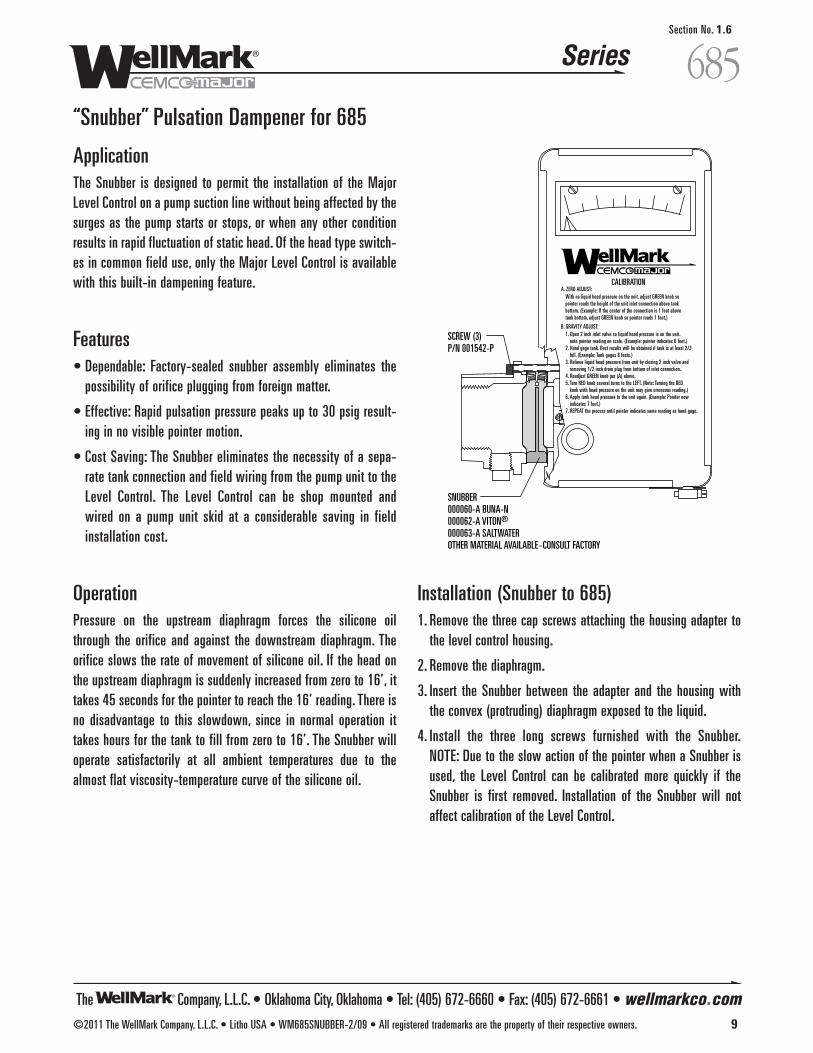
SCREW (3)P/N 001542-P
SNUBBER000060-A BUNA-N000062-A VITON®
000063-A SALTWATEROTHER MATERIAL AVAILABLE-CONSULT FACTORY
CALIBRATIONA. ZERO ADJUST:
B. GRAVITY ADJUST:
With no liquid head pressure on the unit, adjust GREEN knob sopointer reads the height of the unit inlet connection above tankbottom. (Example: If the center of the connection is 1 foot abovetank bottom, adjust GREEN knob so pointer reads 1 foot.)
1. Open 2 inch inlet valve so liquid head pressure is on the unit.note pointer reading on scale. (Example: pointer indicates 6 feet.)
2. Hand gage tank. Best results will be obtained if tank is at least 2/3full. (Example: Tank gages 8 feets.)
3. Relieve liquid head pressure from unit by closing 2 inch valve andremoving 1/2 inch drain plug from bottom of inlet connection.
4. Readjust GREEN knob per (A) above.5. Turn RED knob several turns to the LEFT. (Note: Turning the RED knob with head pressure on the unit may give erroneous reading.)6. Apply tank head pressure to the unit again. (Example: Pointer now
indicates 7 feet.)7. REPEAT the process until pointer indicates same reading as hand gage.
©2011 The WellMark Company, L.L.C. • Litho USA • WM685SNUBBER-2/09 • All registered trademarks are the property of their respective owners. 9
685Section No. 1.6
“Snubber” Pulsation Dampener for 685
ApplicationThe Snubber is designed to permit the installation of the MajorLevel Control on a pump suction line without being affected by thesurges as the pump starts or stops, or when any other conditionresults in rapid fluctuation of static head. Of the head type switch-es in common field use, only the Major Level Control is availablewith this built-in dampening feature.
Features• Dependable: Factory-sealed snubber assembly eliminates the
possibility of orifice plugging from foreign matter.
• Effective: Rapid pulsation pressure peaks up to 30 psig result-ing in no visible pointer motion.
• Cost Saving: The Snubber eliminates the necessity of a sepa-rate tank connection and field wiring from the pump unit to theLevel Control. The Level Control can be shop mounted andwired on a pump unit skid at a considerable saving in fieldinstallation cost.
Operation Pressure on the upstream diaphragm forces the silicone oilthrough the orifice and against the downstream diaphragm. Theorifice slows the rate of movement of silicone oil. If the head onthe upstream diaphragm is suddenly increased from zero to 16’, ittakes 45 seconds for the pointer to reach the 16’ reading. There isno disadvantage to this slowdown, since in normal operation ittakes hours for the tank to fill from zero to 16’. The Snubber willoperate satisfactorily at all ambient temperatures due to thealmost flat viscosity-temperature curve of the silicone oil.
Installation (Snubber to 685)1. Remove the three cap screws attaching the housing adapter to
the level control housing.
2. Remove the diaphragm.
3. Insert the Snubber between the adapter and the housing withthe convex (protruding) diaphragm exposed to the liquid.
4. Install the three long screws furnished with the Snubber.NOTE: Due to the slow action of the pointer when a Snubber isused, the Level Control can be calibrated more quickly if theSnubber is first removed. Installation of the Snubber will notaffect calibration of the Level Control.
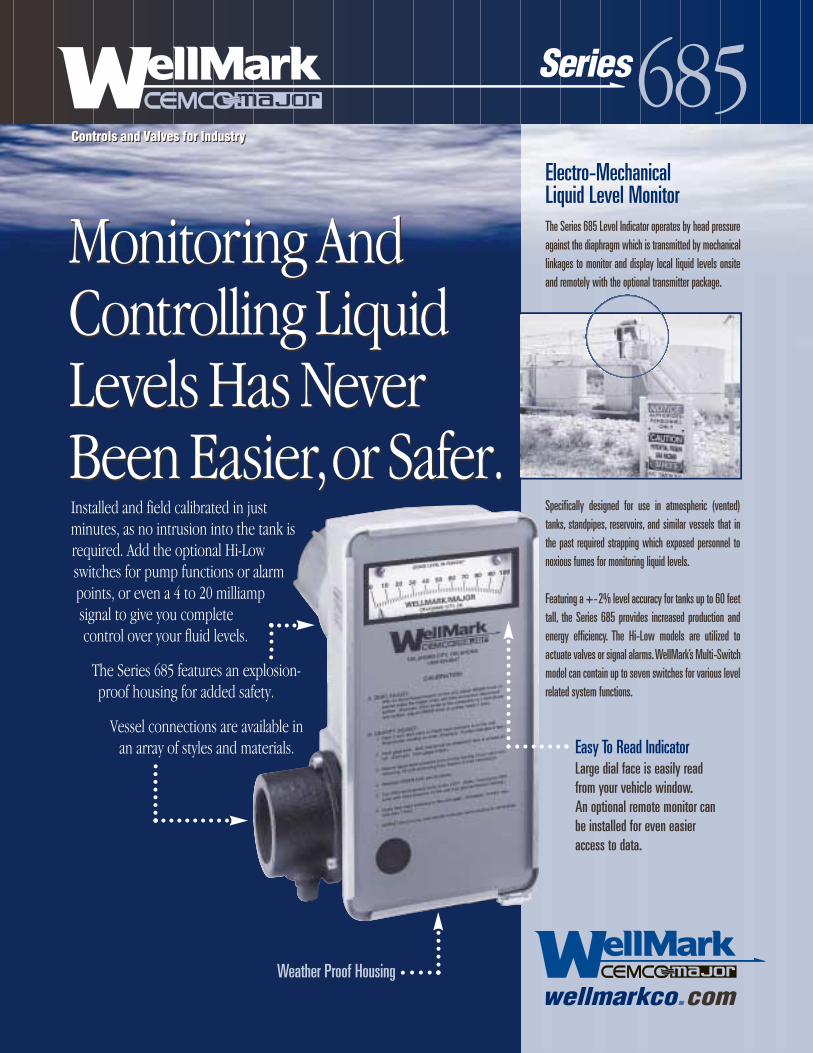
Installed and field calibrated in justminutes, as no intrusion into the tank isrequired. Add the optional Hi-Lowswitches for pump functions or alarmpoints, or even a 4 to 20 milliampsignal to give you completecontrol over your fluid levels.
The Series 685 features an explosion-proof housing for added safety.
Vessel connections are available inan array of styles and materials.
Monitoring AndControlling LiquidLevels Has NeverBeen Easier,or Safer.
Monitoring AndControlling LiquidLevels Has NeverBeen Easier,or Safer.
Easy To Read IndicatorLarge dial face is easily readfrom your vehicle window.An optional remote monitor canbe installed for even easieraccess to data.
Weather Proof Housing
wellmarkco.com
Controls and Valves for IndustryControls and Valves for Industry
685Series
Electro-MechanicalLiquid Level MonitorThe Series 685 Level Indicator operates by head pressureagainst the diaphragm which is transmitted by mechanicallinkages to monitor and display local liquid levels onsiteand remotely with the optional transmitter package.
Specifically designed for use in atmospheric (vented)tanks, standpipes, reservoirs, and similar vessels that inthe past required strapping which exposed personnel tonoxious fumes for monitoring liquid levels.
Featuring a +-2% level accuracy for tanks up to 60 feettall, the Series 685 provides increased production andenergy efficiency. The Hi-Low models are utilized toactuate valves or signal alarms.WellMark’s Multi-Switchmodel can contain up to seven switches for various levelrelated system functions.

AcrylicFront Window
1/2" NPTDrain Plug
S.S. Strap1 7/8"
2 1/16"
Scale
6 1/2" 4 3/8"
12 1/2"
Weather ProofIndicator Housing
Controls and Valves for Industry
685Series
Dimensional Data
©2001 The WellMark Company • WCM685-601 • Litho USA
All component parts are manufactured from highquality materials and each unit is assembled toyour exact specifications.The Wellmark Series 685is easy to access, calibrate and maintain, making itthe superior choice for liquid level management.
Which Model Is Right For You?Model 685I • Indication of local liquid level only.
Model 685S • Indication of local liquid level plusHi-Low switch output for pump start/stop, solenoidaction or single alarm. • Multi-Switch style offersindication of local liquid level with one to sevenswitches for several switching output options.
Model 685E Transmitter • Indication of local liquidlevel with Proportional Output Transmitter for remoteliquid level indication via Computers, ProgrammableControllers and Radio Communication Devices.
Drain Petcock Valve
Model 685
Isolating Valve
Atmospheric Vessel
Liquid LevelBeing Measured
(Span)
wellmarkco.com
Specifications
Typical Installation
Temperature Limit . . . . . . . . . . . . . . . . . . . . . . . . . . . . . . . . . . . . . . . . . . . . . . . . . . . . . . . 300˚ FAccuracy . . . . . . . . . . . . . . . . . . . . . . . . . . . . . . . . . . . . . . . . . . . . . . . . . . . . . . . . . . . . + -2%Housing . . . . . . . . . . . . . . . . . . . . . . . . . . . . . . . . Class I, Groups C & D; Class II, Groups E, F and G:Rating . . . . . . . . . . . . . . . . . . . . . . . . . . . . . . . . . . . . . . . . . . . . . . . . . CSA Approved, LR-41663
The Company1903 S.E. 29th StreetOklahoma City, OK 73129
P.O. Box 95459Oklahoma City, OK 73143
Tel: (405) 672-6660Fax: (405) 672-6661Email: [email protected] your WellMark representative today for more information.
The Company, L.L.C. • Oklahoma City, Oklahoma • Tel: (405) 672-6660 • Fax: (405) 672-6661 • wellmarkco.com
Series
©2011 The WellMark Company, L.L.C. • Litho USA • WM790-2/11 • All registered trademarks are the property of their respective owners. 1
790Section No. 2.1
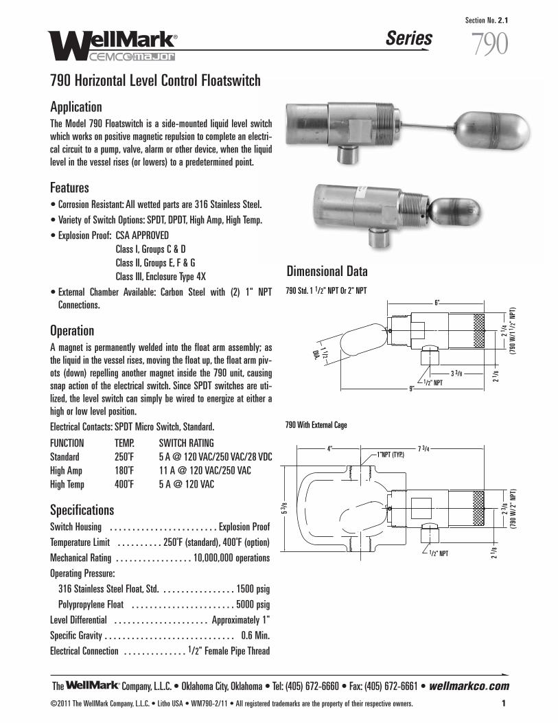
790 Horizontal Level Control Floatswitch
ApplicationThe Model 790 Floatswitch is a side-mounted liquid level switchwhich works on positive magnetic repulsion to complete an electri-cal circuit to a pump, valve, alarm or other device, when the liquidlevel in the vessel rises (or lowers) to a predetermined point.
Features• Corrosion Resistant: All wetted parts are 316 Stainless Steel.
• Variety of Switch Options: SPDT, DPDT, High Amp, High Temp.
• Explosion Proof: CSA APPROVEDClass I, Groups C & DClass II, Groups E, F & GClass III, Enclosure Type 4X
• External Chamber Available: Carbon Steel with (2) 1" NPTConnections.
Operation A magnet is permanently welded into the float arm assembly; asthe liquid in the vessel rises, moving the float up, the float arm piv-ots (down) repelling another magnet inside the 790 unit, causingsnap action of the electrical switch. Since SPDT switches are uti-lized, the level switch can simply be wired to energize at either ahigh or low level position.
Electrical Contacts: SPDT Micro Switch, Standard.
FUNCTION TEMP. SWITCH RATING Standard 250˚F 5 A @ 120 VAC/250 VAC/28 VDCHigh Amp 180˚F 11 A @ 120 VAC/250 VAC High Temp 400˚F 5 A @ 120 VAC
SpecificationsSwitch Housing . . . . . . . . . . . . . . . . . . . . . . . . Explosion Proof
Temperature Limit . . . . . . . . . . 250˚F (standard), 400˚F (option)
Mechanical Rating . . . . . . . . . . . . . . . . . 10,000,000 operations
Operating Pressure:
316 Stainless Steel Float, Std. . . . . . . . . . . . . . . . . 1500 psig
Polypropylene Float . . . . . . . . . . . . . . . . . . . . . . . 5000 psig
Level Differential . . . . . . . . . . . . . . . . . . . . . Approximately 1"
Specific Gravity . . . . . . . . . . . . . . . . . . . . . . . . . . . . . 0.6 Min.
Electrical Connection . . . . . . . . . . . . . . 1/2" Female Pipe Thread
790 Std. 1 1/2" NPT Or 2" NPT
790 With External Cage
1/2" NPT
1"NPT (TYP.)4" 7 3/4
5 3 /
8
2 1 /
8
2 3 /
8(7
90 W
/ 2" N
PT)
6"
3 3/8
2 1 /
8
2 1 /
4(7
90 W
/ 1 1 /
2" N
PT)
1/2" NPT9"
1 1/2DIA.
Dimensional Data

c • External Chamber - Carbon Steel with (2) 1" NPT Connections
e • External Arm (Specify Length)h • High Pressure - 5000 psi
Polypropylene Floats • Stainless Steel Tagx • Annulus Plug
A • 316 S.S. Process Connection with 316 S.S. Trim
The Company, L.L.C. • Oklahoma City, Oklahoma • Tel: (405) 672-6660 • Fax: (405) 672-6661 • wellmarkco.com
Series
2 ©2011 The WellMark Company, L.L.C. • Litho USA • WM790-2/11 • All registered trademarks are the property of their respective owners.
790Section No. 2.1
790 Horizontal Level Control Floatswitch
Determining the Model NumberExample given: Standard Model 790SF-1A Float Control with SPDT Micro Switch, 1 1/2" NPT Vessel Connecton, 316 S.S. Float, 316 S.S.Arm and Pivot for Internal Vessel Mounting with pressure up to 1500 psi.
OPTIONAL PARTS FOR 790
ANNULUS PLUG009522-M
11 7
8
12 1 3 5 4 2
10 9 6
SF • SPDT Dry Contact - STD.SG • DPDT Dry Contact - STD.SK • SPDT High AmpSR • SPDT High Temperature
1 • 1 1/2" NPT2 • 2" NPT
MODEL 790SF-1 A
Size
Type ofSwitch
Options &Additions
Materials
*For variations, change code to match requirements.
WIRING DIAGRAM FOR 790 WITH FLOAT IN DOWN POSITION1 BLACK . . . . . . . . . . . . . . . . . . . . . . . . . . . . . . . . . COMMON2 BLUE . . . . . . . . . . . . . . . . . . . . . . . . . . . NORMALLY CLOSED3 RED . . . . . . . . . . . . . . . . . . . . . . . . . . . . . . NORMALLY OPEN
Parts ListItem Description Qty. Part No.
1 BODY 1 1/2" NPT, ASTM A-276 TY.316 1 009513-MBODY 2" NPT, ASTM A-276 TY.316 1 009527-M
2 FLOAT, 316 STAINLESS STEEL 1 007418-P3 COUNTER WEIGHT, ASTM A-276 TY.316 1 007361-W4 PIVOT PIN, 316 S.S. 1 007233-P5 SPACER, 316 S.S. 2 007114-M6 ADAPTER, ASTM A-582 TY.303 1 009533-M
7 SWITCH ASSY, SPDT 1 009584-ASWITCH ASSY, DPDT 1 009679-A
8 SWITCH PROTECTOR, 304SS 1 009520-P9 LOCK WASHER, S.S. 2 001804-P
10 SCREW, 18-8 S.S. 2 001504-P11 CAP, 303 STAINLESS STEEL 1 009514-M12 O-RING, BUNA-N 1 05000-017313* SCREW, GROUND, 18-8 S.S. 1 001504-G14* GROUND CUP, S.S. 1 001800-P15* GROUND WIRE (FOR DPDT SWITCH ONLY) 1 000087-A
*NOT SHOWN

The Company, L.L.C. • Oklahoma City, Oklahoma • Tel: (405) 672-6660 • Fax: (405) 672-6661 • wellmarkco.com
Series
©2011 The WellMark Company, L.L.C. • Litho USA • WM683-2/11 • All registered trademarks are the property of their respective owners. 3
683Section No. 2.2
683 Floatswitch for Atmospheric Vessels up to 2 psig
ApplicationThe Model 683 Floatswitch is a float type control which com-pletes an electrical circuit to a pump, valve, alarm or other device,when the liquid level in the vessel rises (or lowers) to a prede-termined point.
Features• Corrosion Proof: Float and Arm are 304 S.S., Cad Plated Steel
Vessel Connection (Other materials available for more corrosiveliquids).
• No Wearing Parts: Due to the pivoting action of the float arm onthe diaphragm, sticking does not occur in thick or corrosive liquids.
• Variety of Switch Outputs: The 683 can be obtained with mercu-ry or micro switch output and in various combinations, ie. SPST,SPDT, DPDT, etc.
• Adjustments: Nothing to adjust or get out of calibration on themercury switches. Micro switches can be adjusted from the out-side when the floatswitch is installed on the vessel.
• Simple Installation: On an INTERNAL MOUNT, the float passesthrough a 2" nipple. On an EXTERNAL MOUNT, install on 2" exter-nal pipe riser connected to the pressure vessel above the highlevel and below the low level control points.
• Longer Life: Since there are no wearing parts, the replacement ofstuffing boxes, etc. is eliminated.
Operation The float arm passes through a nylon reinforced diaphragm with aspecial nut on each side of the diaphragm; the switches areattached to the float arm by means of stainless steel supports. Thediaphragm acts as a pivot point for the float arm, and as a sealbetween the vessel and the explosion proof switch housing. Themaximum travel of the float between the switch “make” and"break" is 1" for mercury switches and 1/4" for micro switches.
SpecificationsSwitch Housing . . . . . . . . . . . . . . . . . . . . . . . . . Cast Aluminum
Operating Pressure . . . . . . . . . . . . . . . . . Atmospheric to 2 psig
Operating Temperature . . . . . . . . . . . . . . . . . . -20˚F to +225˚F
Electrical Connection . . . . . . . . . . . . . . 1/2" Female Pipe Thread
1 3/4"
4 3/8"
1/2" NPTConnection
3 3/8"7 3/4" 4 1/4"
2"
4" 4" 3 1/8" 3"
4 1/4"5 1/2"3 1/4"
7 1/2"
1/2" NPTConnection
2" THREADED NPT (3 PLACES)External Type
Internal Type
2" Threaded NPT
2" Grooved
2" Threaded NPT2"-150# RF Flange 45˚
6"
4 3/8"
9 1/4" 6 1/8"
Dimensional Data
Switch Ratings
683SA, 683SB . . . . . . . . . . . . . . . . . . . . . . . . SPST Mercury10 A @120 VAC, 5 A @ 240 VAC
3 A @ 440 VAC
683SC . . . . . . . . . . . . . . . . . . . . . . . . . . . . . . SPDT Mercury4 A @ 120 VAC, 2 A @ 240 VAC
1 A @ 440 VAC
683SF . . . . . . . . . . . . . . . . . . . . . . . . . . . SPDT Micro Switch15 A @ 125, 250 or 480 VAC
1/8 HP-125 VAC, 1/4 HP-250 VAC1/2 A @ 125 VDC, 1/4 A @ 250 VDC
683SG . . . . . . . . . . . . . . . . . . . . . . . . . . DPDT Micro Switch10 A @ 125 or 250 VAC
0.3 A @ 125 VDC; 0.15 A @ 250 VDC

The Company, L.L.C. • Oklahoma City, Oklahoma • Tel: (405) 672-6660 • Fax: (405) 672-6661 • wellmarkco.com
Series
4 ©2011 The WellMark Company, L.L.C. • Litho USA • WM683-2/11 • All registered trademarks are the property of their respective owners.
683Section No. 2.2
683 Floatswitch for Atmospheric Vessels up to 2 psig
Determining the Model NumberExample given: Standard Model 683-A1A1-IN Floatswitch for Atmospheric (Vented) Vessels with, SPDT Micro Switch Output, 2" NPT (CadPlated Steel) Vessel Connection, 304 S.S. Float and Float Arm, Buna-N Diaphragm, for Internal Vessel Mounting.
Typical Assembly
a • Ext. Float Housing, Epoxy Coatedb • Ext. Float Housing, Teflon® Coatedg • Float Arm, (Non-Std.) 304 S.S.h • Float Arm, (Non-Std.) 316 S.S.s • Tag, Stainless Steel
N • None RequiredE • EpoxyT • Teflon®
I • Internal (None)X • External (Cad Plated Ductile)
ASTM A-536-GR65-45-12
1 • Buna-N2 • Teflon®
3 • Viton®
F • SPDT Micro SwitchG • DPDT Micro Switch
1 • 2" NPT, Cad Plated Steel2 • 2" NPT, 304 S.S.3 • 2" NPT, 316 S.S.4 • 2"-150# RF Flange,
Cad Plated Steel5 • 2"-150# RF Flange, 304 S.S.6 • 2"-150# RF Flange, 316 S.S.7 • 2" Grooved,
Cad Plated Steel
A • 304 S.S.B • 316 S.S.
Float & Arm Material
MODEL 683S- F 1 A 1-I N
Connection
Type of Switch
Options &Additions
Type ofCoating
Float ControlHousing
DiaphragmsMaterial
683 WITH MERCURY SWITCH683 WITH MICRO SWITCH
ADAPTER2" NPT SHOWN
S.S. FLOAT ARM
S.S. FLOAT
ALUM. COVER ALUM. HOUSING
DIAPHRAGMMICRO SWITCHSPDT SHOWN
MERCURY SWITCHSPST (N.O.) SHOWN
DIAPHRAGM NUT 2" ANSI 150RFFLANGE
*For variations, change code to match requirements.

The Company, L.L.C. • Oklahoma City, Oklahoma • Tel: (405) 672-6660 • Fax: (405) 672-6661 • wellmarkco.com
Series
©2011 The WellMark Company, L.L.C. • Litho USA • WM686-2/11 • All registered trademarks are the property of their respective owners. 5
686Section No. 2.3
686 Floatswitch for Pressure Vessels up to 200 psig
ApplicationThe Model 686S Floatswitch is a float type control which completesan electrical circuit to a pump, valve, alarm or other device, when theliquid in the vessel rises (or lowers) to a pre-determined point.
Features• Corrosion Proof: Float and Arm are 304 S.S., Cad Plated Steel Vessel
Connection (Other materials available for more corrosive liquids).• Explosion Proof: CSA Approved
Class I Group DClass II Group E, F and GHazardous Locations
• Variety of Switch Outputs: The 686 can be obtained with mercu-ry or micro switch outputs and in various combinations, ie.; SPDT,SPST, DPDT, etc.
• Adjustments: Nothing to adjust or get out of calibration on themercury switch. Micro switches can be adjusted from the outsidewhen the floatswitch is installed on the vessel.
• Simple Installation: On an INTERNAL MOUNT, the float passesthrough a 2" nipple. On an EXTERNAL MOUNT, install on 2" exter-nal pipe riser connected to the pressure vessel above the highlevel and below the low level control points.
• Long Life: Permanently dry-film lubricated S.S. shaft and Teflon®
bearing comprise the only pivot point. Due to large bearing sur-face area, wear is negligible.
Operation The Float and Arm are rigidly attached to the dry-film lubricatedshaft which rotates in the shaft housing. A bracket at the other endof the shaft actuates the switch. A Viton® O-Ring seals againstpressure and leakage along the shaft.A Teflon® washer separates the metal parts and provides lubricity. Ifleakage ever occurs, the liquid in the vessel seeps out of the safetyvent hole. Thus, it is impossible for the liquid to ever enter the switchhousing. The maximum travel of the float between the switch "make"and "break" is 1" for mercury switches and 1/4" for micro switches.
SpecificationsSwitch Housing . . . . . . . . . . . . . Explosion Proof Cast Aluminum
Operating Pressure . . . . . . . . . . . . . . . . . . . . . . . 0 to 200 psig
Proof Pressure . . . . . . . . . . . . . . . . . . . . . . . . . . . . . . 400 psig
Operating Temperature . . . . . . . . . . . . . . . . . . -20˚F to +400˚F
External Float Housing . . . . . . . . . . . . . . . . . . . . . . Ductile Iron
Electrical Connection . . . . . . . . . . . . . . 1/2" Female Pipe Thread
Internal Type
4 3/8"
4 5/8" 1 3/4"
1 3/4"
4 5/8"
4 3/8"
1/2" NPTConnection
SafetyVent Hole
7 1/2"
SafetyVent Hole
External Type
3 3/8"7 7/8" 4 1/4"
2"
4" 4 1/8" 3 1/8" 3"
4 1/4"5 1/2"3 1/4"
7 1/2"
1/2" NPTConnection
2" Threaded NPT
2" Grooved
2" Threaded NPT2"-150# R.F. ASA Flange 45˚
2" THREADED NPT (3 PLACES)
Dimensional Data
Switch Ratings686SA, 686SB . . . . . . . . . . . . . . . . . . . . . . . . SPST Mercury
10 A @120 VAC, 5 A @ 240 VAC3 A @ 440 VAC
686SC . . . . . . . . . . . . . . . . . . . . . . . . . . . . . . SPDT Mercury4 A @ 120 VAC, 2 A @ 240 VAC
1 A @ 440 VAC686SF . . . . . . . . . . . . . . . . . . . . . . . . . . . SPDT Micro Switch
15 A @ 125, 250 or 480 VAC1/8 HP-125 VAC, 1/4 HP-250 VAC
1/2 A @ 125 VDC, 1/4 A @ 250 VDC686SG . . . . . . . . . . . . . . . . . . . . . . . . . . DPDT Micro Switch
10 A @ 125 or 250 VAC0.3 A @ 125 VDC; 0.15 A @ 250 VDC

The Company, L.L.C. • Oklahoma City, Oklahoma • Tel: (405) 672-6660 • Fax: (405) 672-6661 • wellmarkco.com
Series
1
Shaft Collar
Teflon® WasherO-Ring
ShaftHousing
Insulator
CoverAdapter
Pivot ShaftHousing
Actuation Arm
Bracket
S.S. Float Arm
S.S. Float
686 WITH MICRO SWITCH
686 WITH MERCURY SWITCHSwitch Support
Insulator
Terminal Strip Cover
GroundScrew
Micro SwitchSPDT Shown
ANSI Flange
GroundScrew
Bushing
Switch w/Holder
6 ©2011 The WellMark Company, L.L.C. • Litho USA • WM686-2/11 • All registered trademarks are the property of their respective owners.
686Section No. 2.3
686 Floatswitch for Pressure Vessels up to 200 psig
Determining the Model NumberExample given: Standard Model 686SA-1A-IN Float Control for Vented Vessels up to 200 psig with, SPDT Micro Switch Output, 2" NPT(Cad Plated Steel) Vessel Connection, 304 S.S. Float and Float Arm, for Internal Vessel Mounting.
Typical Assembly
a • Ext. Float Housing, Epoxy Coatedb • Ext. Float Housing, Teflon® Coatedg • Float Arm, (Non-Std.) 304 S.S.h • Float Arm, (Non-Std.) 316 S.S.
m • Manual Overrides • Tag, Stainless Steel
N • None RequiredE • EpoxyT • Teflon®
I • Internal (None)X • External (Cad Plated Ductile)
ASTM A-536-GR65-45-12
A • 304 S.S.B • 316 S.S.
SF • SPDT Micro SwitchSG • DPDT Micro Switch
1 • 2" NPT, Cad Plated Steel2 • 2" NPT, 304 S.S.3 • 2" NPT, 316 S.S.4 • 2"-150# ASARF Flange,
Cad Plated Steel5 • 2"-150# ASARF Flange,
304 S.S.6 • 2"-150# ASARF Flange,
316 S.S.7 • 2" Grooved, Cad Plated Steel
MODEL 686 SF -1 A-I N
Connection
Type of Switch
Options &Additions
Type ofCoating
Float ControlHousing
Float & ArmMaterial

The Company, L.L.C. • Oklahoma City, Oklahoma • Tel: (405) 672-6660 • Fax: (405) 672-6661 • wellmarkco.com
Series
©2011 The WellMark Company, L.L.C. • Litho USA • WM687-2/11 • All registered trademarks are the property of their respective owners. 7
687Section No. 2.4
687 Floatswitch for Pressure Vessels up to 1440 psig
ApplicationThe Model 687 Floatswitch is a float type control which completesan electrical circuit to a pump, valve, alarm, or other device, whenthe liquid in the vessel rises (or lowers) to a pre-determined point.
Features• Corrosion Proof: Float and Arm is 304 S.S., 2" Cad Plated Steel
Vessel Connection or Cast Steel External Cage (Other materialsare available for more corrosive liquids).
• Explosion Proof: CSA Approved for Class I Group D, Class II GroupE, F and G hazardous locations.
• Variety of Switch Outputs: The 687 can be obtained with mercuryor microswitch outputs and in various combinations, ie. SPDT,SPST, DPDT, etc.
• Adjustments: Nothing to adjust or get out of calibration on themercury switch. Micro switches can be adjusted from the outsidewhen the floatswitch is installed on the vessel.
• Simple Installation: On an INTERNAL MOUNT, the float passesthrough a 2" nipple. On an EXTERNAL MOUNT, install on 1" exter-nal pipe riser connected to the pressure vessel above the highlevel and below the low level control points.
• Long Life: Permanently dry-film lubricated S.S. shaft and Teflon®
bearing comprise the only pivot point. Due to large bearing sur-face area, wear is negligible.
Operation The float and arm are rigidly attached to the dry-film lubricatedshaft which rotates in the shaft housing. A bracket at the other endof the shaft actuates the switch. A Viton® o-ring seals againstpressure and leakage along the shaft. A Teflon® washer separatesthe metal parts and provides lubricity. If leakage ever occurs, theliquid in the vessel seeps out of the safety vent hole. Thus, it isimpossible for the liquid to ever enter the switch housing. The max-imum travel of the float between the switch "make" and "break" is1" for mercury switches and 1/4" for micro switches.
SpecificationsSwitch Housing . . . . . . . . . . . . . Explosion Proof Cast Aluminum
Operating Pressure . . . . . . . . . . . . . . . . . . . . . . 0 to 1440 psig
Proof Pressure . . . . . . . . . . . . . . . . . . . . . . . . . . . . . 2000 psig
Operating Temperature . . . . . . . . . . . . . . . . . . -20˚F to +400˚F
External Float Housing . . . . . . . . . . . . . . . . . . . . . . . Cast Steel
Electrical Connection . . . . . . . . . . . . . . 1/2" Female Pipe Thread
Safety Vent Hole1/2" NPTConnection 1 3/4"4 5/8"
4 3/8"
7 1/2"6" 3 1/8"
4 1/4"17 1/2"
2" Threaded NPT
2"
19"
10 3/4" 4 1/4"
1" NPT
1" NPT
1" NPT (Optional)
1/2" Electrical Connection
5" 1 3/4"
4 3/8"6 3/8"
Safety Vent Hole
8 1/2"
Internal Type
External Type
Dimensional Data
Switch Ratings687SA, 687SB . . . . . . . . . . . . . . . . . . . . . . . . SPST Mercury
10 A @120 VAC, 5 A @ 240 VAC3 A @ 440 VAC
687SC . . . . . . . . . . . . . . . . . . . . . . . . . . . . . . SPDT Mercury4 A @ 120 VAC, 2 A @ 240 VAC
1 A @ 440 VAC687SF . . . . . . . . . . . . . . . . . . . . . . . . . . . SPDT Micro Switch
15 A @ 125, 250 or 480 VAC1/8 HP-125 VAC, 1/4 HP-250 VAC
1/2 A @ 125 VDC, 1/4 A @ 250 VDC687SG . . . . . . . . . . . . . . . . . . . . . . . . . . DPDT Micro Switch
10 A @ 125 or 250 VAC0.3 A @ 125 VDC; 0.15 A @ 250 VDC
The Company, L.L.C. • Oklahoma City, Oklahoma • Tel: (405) 672-6660 • Fax: (405) 672-6661 • wellmarkco.com
Series
8 ©2011 The WellMark Company, L.L.C. • Litho USA • WM687-2/11 • All registered trademarks are the property of their respective owners.
687Section No. 2.4
687 Floatswitch for Pressure Vessels up to 1440 psig
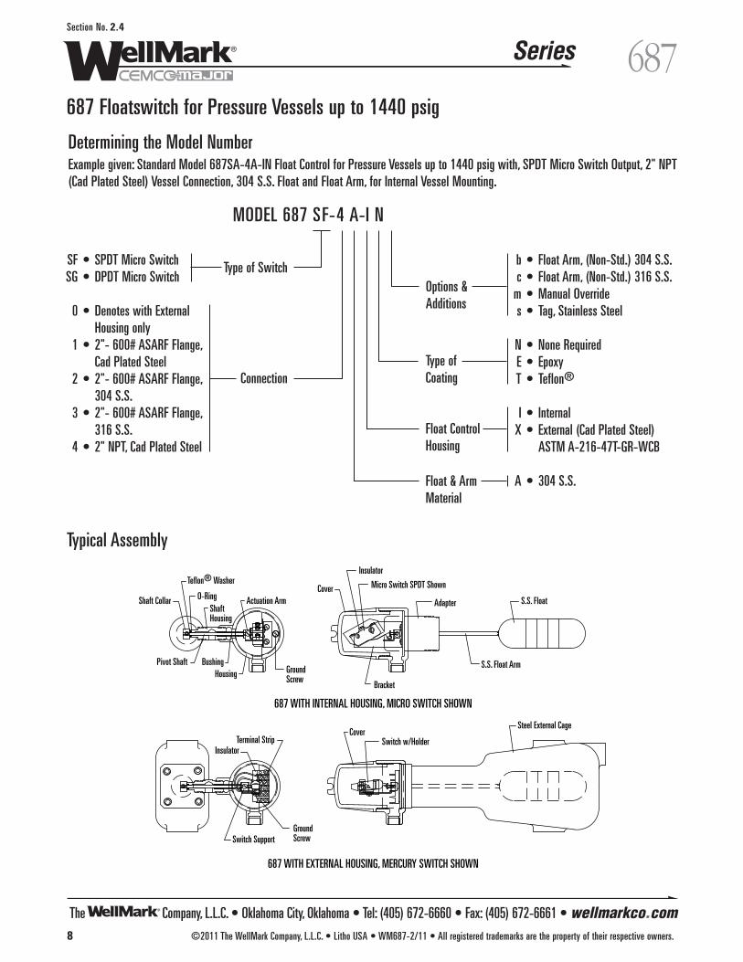
Determining the Model NumberExample given: Standard Model 687SA-4A-IN Float Control for Pressure Vessels up to 1440 psig with, SPDT Micro Switch Output, 2" NPT(Cad Plated Steel) Vessel Connection, 304 S.S. Float and Float Arm, for Internal Vessel Mounting.
Typical Assembly
b • Float Arm, (Non-Std.) 304 S.S.c • Float Arm, (Non-Std.) 316 S.S.
m • Manual Overrides • Tag, Stainless Steel
N • None RequiredE • EpoxyT • Teflon®
I • InternalX • External (Cad Plated Steel)
ASTM A-216-47T-GR-WCB
A • 304 S.S.
SF • SPDT Micro SwitchSG • DPDT Micro Switch
0 • Denotes with External Housing only
1 • 2"- 600# ASARF Flange, Cad Plated Steel
2 • 2"- 600# ASARF Flange, 304 S.S.
3 • 2"- 600# ASARF Flange, 316 S.S.
4 • 2" NPT, Cad Plated Steel
MODEL 687 SF-4 A-I N
Connection
Type of SwitchOptions &Additions
Type ofCoating
Float ControlHousing
Float & ArmMaterial
687 WITH INTERNAL HOUSING, MICRO SWITCH SHOWN
687 WITH EXTERNAL HOUSING, MERCURY SWITCH SHOWN
Steel External Cage
Shaft Collar O-RingShaftHousing
Insulator
Cover
Adapter
Pivot Shaft BushingHousing
Actuation Arm
Bracket
S.S. Float Arm
S.S. Float
Switch Support
InsulatorTerminal Strip
CoverSwitch w/Holder
GroundScrew
Micro Switch SPDT Shown
GroundScrew
Teflon® Washer

The Company, L.L.C. • Oklahoma City, Oklahoma • Tel: (405) 672-6660 • Fax: (405) 672-6661 • wellmarkco.com
Series
©2011 The WellMark Company, L.L.C. • Litho USA • WM688-2/11 • All registered trademarks are the property of their respective owners. 9
688Section No. 2.5
688 Level Switch for Pressure Vessels up to 2000 psig
ApplicationThe Model 688 is a single point on/off level switch, which com-pletes an electrical circuit to a pump, valve, alarm or otherdevise. This unit senses virtually any liquid and does not needadjustment when the vessel contents are changed. It will ignorefoam, surge or splash to indicate true liquid level, with repeata-bility to 0.050 in. standard.
Features• Fail-Safe: Unit is field adjusted to high or low level fail-safe
conditions.• Auto Test Self-Checking: The unique self-checking feedback loop
constantly "proves" that the switch is working properly andoffers superior reliability in critical applications.
• Long Life: The all stainless steel, heavy-duty sensor resists damagefrom product abrasion or corrosion. No packing glands are used.
• Explosion Proof: CSA Approved for Class I Group C & D, Class IIGroup E, F and G hazardous locations
• Versatile Power Supply: The standard units are designed toaccept 115 VAC, 230 VAC or low voltage AC or DC input power.
Operation When liquid touches the sensor it starts a chain of activity through-out the sensors internal components, which in turn sends a signal tothe circuit board inside the housing. A red LED is illuminated how-ever if there is a sensor failure or other component failure, the relaywill immediately transfer to the alarm condition.
InstallationThe 688 mounts in many positions.
7 /8
Dia. 1" NPT
1/2 NPT
1/2 NPT
2" NPTANSI Flange
688 WITH EXTENSION PROBE
688 LEVEL SWITCH
4 1/2
Dia.
3 3/4 5 1/2 1 1/2
5 1/2 Extension 36" Max.Specify When Order
SpecificationsElectrical Housing . . . . . . . . . . . . . . . . . . . . . . . . CSA Approved
Class I, Groups C & D; Class II Groups E, F and GHousing Operating Temperature . . . . . . Ambient -20˚F to +160˚FOperating Pressure . . . . . . . . . . . . . . . . . . . . . Up to 2000 psigSensor Operating Temperature . . . . . . . . . . . . . -20˚F to +220˚F ElectricalInput Voltage . . . . . . . . . . . Nominal: 115 VAC, 230 VAC, 24 VDCAbsolute Limits . . . . . . . . 90-135 VAC, 180-270 VAC, +-4 VDCFrequency . . . . . . . . . . . . . . . . . . . . . . . . . AC Power: 50-60 HzTime Delay . . . . . Independent, non-integrating on make and brake.Delay Time Range . . . . . . . . . . . . . . . . . . . 50 milliseconds min.,
long delay, 30 sec. max.Output . . . . . . . . . . . . . . . . . . . . . . Relay DPDT Form C ContactsRatings . . . . . . . . . . . . . . . . . . . 5A @ 120 VAC Non-Inductive,
5 A @ 24 VDC Non-Inductive.
Dimensional DataVertical Installation
Top Mount “Extended Probe”
Overflow Liquid Level Switch
High/Low Liquid Level Switch
The Company, L.L.C. • Oklahoma City, Oklahoma • Tel: (405) 672-6660 • Fax: (405) 672-6661 • wellmarkco.com
Series
10 ©2011 The WellMark Company, L.L.C. • Litho USA • WM688-2/11 • All registered trademarks are the property of their respective owners.
688Section No. 2.5
688 Level Switch for Pressure Vessels up to 2000 psig
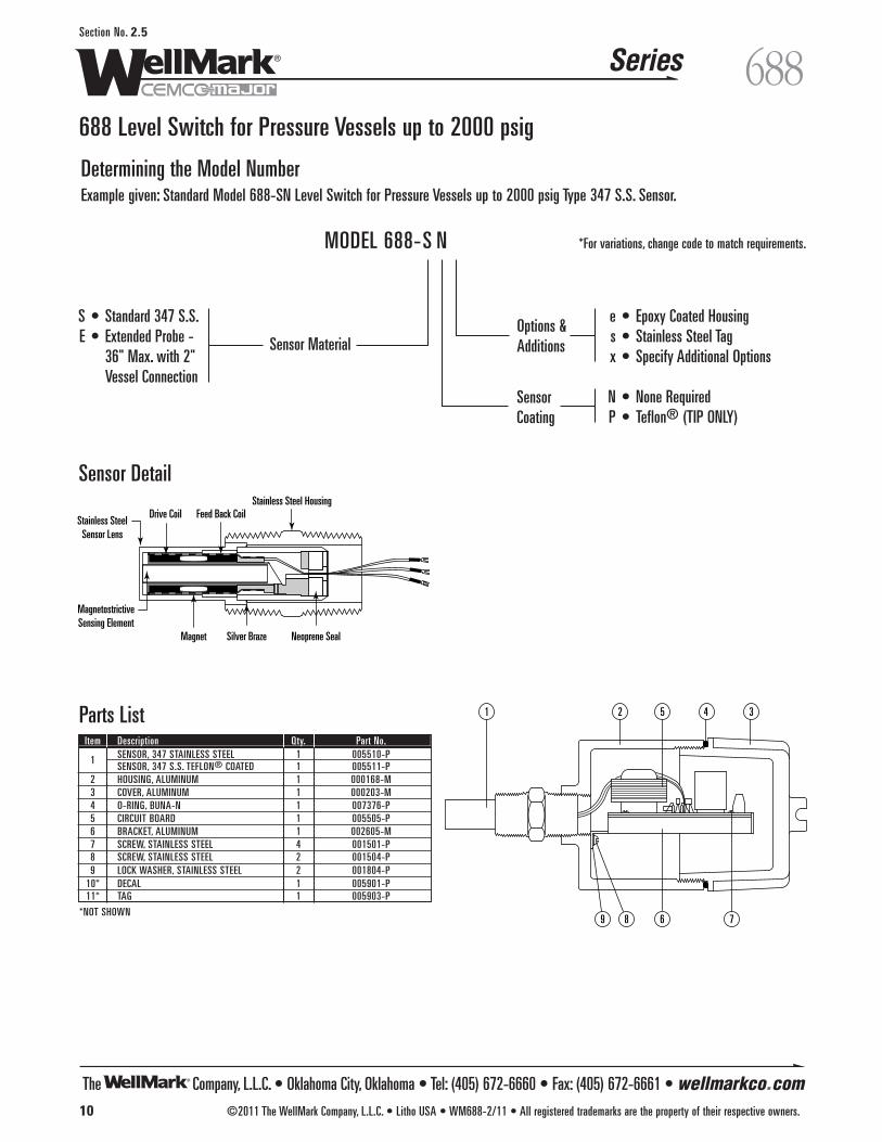
Determining the Model NumberExample given: Standard Model 688-SN Level Switch for Pressure Vessels up to 2000 psig Type 347 S.S. Sensor.
78
1 35 42
69
Parts List
Sensor Detail
Item Description Qty. Part No.
1 SENSOR, 347 STAINLESS STEEL 1 005510-PSENSOR, 347 S.S. TEFLON® COATED 1 005511-P
2 HOUSING, ALUMINUM 1 000168-M3 COVER, ALUMINUM 1 000203-M4 O-RING, BUNA-N 1 007376-P5 CIRCUIT BOARD 1 005505-P6 BRACKET, ALUMINUM 1 002605-M7 SCREW, STAINLESS STEEL 4 001501-P8 SCREW, STAINLESS STEEL 2 001504-P9 LOCK WASHER, STAINLESS STEEL 2 001804-P
10* DECAL 1 005901-P11* TAG 1 005903-P
*NOT SHOWN
e • Epoxy Coated Housings • Stainless Steel Tagx • Specify Additional Options
N • None RequiredP • Teflon® (TIP ONLY)
S • Standard 347 S.S.E • Extended Probe -
36" Max. with 2" Vessel Connection
MODEL 688-S N
Sensor MaterialOptions &Additions
SensorCoating
*For variations, change code to match requirements.
MagnetostrictiveSensing Element
Stainless SteelSensor Lens
Drive Coil Feed Back CoilStainless Steel Housing
Magnet Silver Braze Neoprene Seal

The Company, L.L.C. • Oklahoma City, Oklahoma • Tel: (405) 672-6660 • Fax: (405) 672-6661 • wellmarkco.com
Series
©2011 The WellMark Company, L.L.C. • Litho USA • WM710-2/11 • All registered trademarks are the property of their respective owners. 11
710Section No. 2.6
710 Flanged Cage Level Control
ApplicationThe Model 710 Series are float-operated units designed for exter-nal mounting to the process vessel and provide high pressure capa-bilities with low specific gravity ratings within the petroleum,power and natural gas industries. These models provide reliablemagnetic switching for level alarm or control function applications.
Features• Construction Versatility: Standard Level Control includes a Carbon
Steel float cage with a choice of threaded, socket-weld orflanged tank connection. Consult factory for other materials.
• Explosion Proof: CSA APPROVEDClass I, Division I, Groups C & DClass II, Groups E, F & GClass III, Enclosure Type 4
• Various Models: A wide selection of cage & trim materials andswitch mechanisms are available.
• 100% Hydrostatic Test @11/2 Times Related Pressure.
Operation As the liquid rises, the float moves the attached magnetic attractionsleeve into the field of the magnet located in the switch housing. Asthis magnet swings toward the enclosing tube, it causes themicroswitch to actuate. As the liquid level falls, the magneticattraction sleeve moves out of the magnetic field and the biasspring pulls the magnet away from the enclosing tube, which deac-tuates the micro switch.
SpecificationsSwitch Housing . . . . . . . . . . . . . Explosion Proof Cast AluminumOperating Pressure . . . . . . . . . . . . . . . . . . . . . . . 350 psi Max. Operating Temperature . . . . . . . . . . . . . . . . . . . . . . 450˚F Max.Minimum Specific Gravity . . . . . . . . . . . . . . . . . . . . . . . . . 0.69 Electrical Connections . . . . . . . . . . . . 1 1/4" Female Pipe Thread Electrical Contacts . . . . . . . . . . . . . SPDT Micro Switch standardFUNCTION AMBIENT TEMP SWITCH RATING Standard -20 to 160˚F 5A @ 250 VAC High Temp -20 to 450˚F 5A @ 250 VAC
ANSI FLANGE CONNECTION(SIDE/BOTTOM)
10 9 /
16
13"
5 3/4
1"NPT OR 1" SOCKET-WELDCONNECTION (SIDE/BOTTOM)
1 1/4" NPT
7 1 /
2 13
"
3 1 /8
3 7/8 4 5/8 Dia.
2 11/16
ANSI FLANGE CONNECTION(SIDE/SIDE)
1"NPT DrainOptional
13"
11 3 /
16
5 3/4
Dimensional Data
The Company, L.L.C. • Oklahoma City, Oklahoma • Tel: (405) 672-6660 • Fax: (405) 672-6661 • wellmarkco.com
Series
12 ©2011 The WellMark Company, L.L.C. • Litho USA • WM710-2/11 • All registered trademarks are the property of their respective owners.
710Section No. 2.6
710 Flanged Cage Level Control
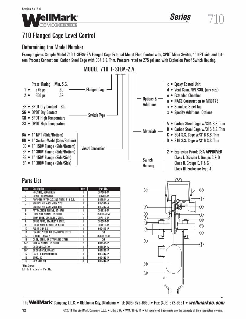
Determining the Model NumberExample given: Sample Model 710 1-SFBA-2A Flanged Cage External Mount Float Control with, SPDT Micro Switch, 1" NPT side and bot-tom Process Connections, Carbon Steel Cage with 304 S.S. Trim, Pressure rated to 275 psi and with Explosion Proof Switch Housing.
c • Epoxy Coated Unitd • Vent Conn. NPT/SOL (any size)e • Extended Chambern • NACE Construction to MR0175s • Stainless Steel Tagx • Specify Additional Options
A • Carbon Steel Cage w/304 S.S. TrimB • Carbon Steel Cage w/316 S.S. TrimC • 304 S.S. Cage w/316 S.S. TrimD • 316 S.S. Cage w/316 S.S. Trim
2 • Explosion Proof: CSA APPROVEDClass I, Division I, Groups C & DClass II, Groups E, F & GClass III, Enclosure Type 4
Press. Rating Min. S.G.1 • 275 psi .692 • 350 psi .69
SF • SPDT Dry Contact - Std.SG • DPDT Dry ContactSR • SPDT High TemperatureSS • DPDT High Temperature
BA • 1" NPT (Side/Bottom)BB • 1" Socket-Weld (Side/Bottom) BE • 1" 150# Flange (Side/Bottom)BF • 1" 300# Flange (Side/Bottom)SE • 1" 150# Flange (Side/Side)SF • 1" 300# Flange (Side/Side)
MODEL 710 1- SFBA-2 A
Switch Type
Flanged Cage
Options &Additions
Materials
SwitchHousing
Vessel Connection
2
1
3
45
6 7
8
9
12
11
10
13
17
1819
6
Parts ListItem Description Qty. Part No.
1 HOUSING, ALUMINUM 1 007201-M2 COVER, ALUMINUM 1 000203-M3 ADAPTER W/ENCLOSING TUBE, 316 S.S. 1 007524-A
4 SWITCH KIT ASSEMBLY, SPDT 1 009341-ASWITCH KIT ASSEMBLY, DTDT 1 009342-A
5 ATTRACTION SLEEVE, 17-4PH 1 009532-M6 LOCK NUT, STAINLESS STEEL 5 05000-22527 STOP TUBE, STAINLESS STEEL 1 007119-M8 GUIDE PLUG, STAINLESS STEEL 1 002304-M9 FLOAT ARM, STAINLESS STEEL 1 009413-M
10 FLOAT, 304 S.S. 1 007410-P11 FLANGE, STEEL OR STAINLESS STEEL 1 C/F12 O-RING, BUNA-N 1 05000-544613 CAGE, STEEL OR STAINLESS STEEL 1 C/F14* SCREW, STAINLESS STEEL 2 001501-P15* GROUND SCREW 1 001504-G16* GROUND CUP, BRASS 1 001800-P17 GASKET, COMPOSITION 1 009442-P18 STUD, B7 4 009443-P19 HEX NUT, 2H 8 009444-P
*Not ShownC/F: Call factory for Part No.
The Company, L.L.C. • Oklahoma City, Oklahoma • Tel: (405) 672-6660 • Fax: (405) 672-6661 • wellmarkco.com
Series
©2011 The WellMark Company, L.L.C. • Litho USA • WM720-2/11 • All registered trademarks are the property of their respective owners. 13
720Section No. 2.7
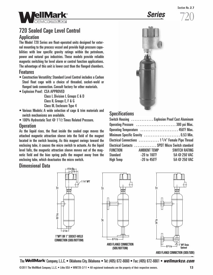
720 Sealed Cage Level ControlApplicationThe Model 720 Series are float-operated units designed for exter-nal mounting to the process vessel and provide high pressure capa-bilities with low specific gravity ratings within the petroleum,power and natural gas industries. These models provide reliablemagnetic switching for level alarm or control function applications.The advantage of this unit is lower cost than the flanged chambers.
Features• Construction Versatility: Standard Level Control includes a Carbon
Steel float cage with a choice of threaded, socket-weld orflanged tank connection. Consult factory for other materials.
• Explosion Proof: CSA APPROVEDClass I, Division I, Groups C & DClass II, Groups E, F & GClass III, Enclosure Type 4
• Various Models: A wide selection of cage & trim materials andswitch mechanisms are available.
• 100% Hydrostatic Test @ 11/2 Times Related Pressure.
Operation As the liquid rises, the float inside the sealed cage moves theattached magnetic attraction sleeve into the field of the magnetlocated in the switch housing. As this magnet swings toward theenclosing tube, it causes the micro switch to actuate. As the liquidlevel falls, the magnetic attraction sleeve moves out of the mag-netic field and the bias spring pulls the magnet away from theenclosing tube, which deactuates the micro switch.
Dimensional Data
SpecificationsSwitch Housing . . . . . . . . . . . . . Explosion Proof Cast AluminumOperating Pressure . . . . . . . . . . . . . . . . . . . . . . . 300 psi Max. Operating Temperature . . . . . . . . . . . . . . . . . . . . . . 450˚F Max.Minimum Specific Gravity . . . . . . . . . . . . . . . . . . . . . 0.53 Min. Electrical Connections . . . . . . . . . . . . 1 1/4" Female Pipe Thread Electrical Contacts . . . . . . . . . . . . . SPDT Micro Switch standardFUNCTION AMBIENT TEMP SWITCH RATING Standard -20 to 160˚F 5A @ 250 VAC High Temp -20 to 450˚F 5A @ 250 VAC
ANSI FLANGE CONNECTION (SIDE/SIDE)
1" NPT DrainOptional6 11/16
14 7 /
813
"
ANSI FLANGE CONNECTION(SIDE/BOTTOM)
6 11/16
14"
13"
1"NPT OR 1" SOCKET-WELDCONNECTION (SIDE/BOTTOM)
1 1/4" NPT
3 1/8
10 7 /
1613
"
4 5/8 Dia.3 7/8
The Company, L.L.C. • Oklahoma City, Oklahoma • Tel: (405) 672-6660 • Fax: (405) 672-6661 • wellmarkco.com
Series
14 ©2011 The WellMark Company, L.L.C. • Litho USA • WM720-2/11 • All registered trademarks are the property of their respective owners.
720Section No. 2.7
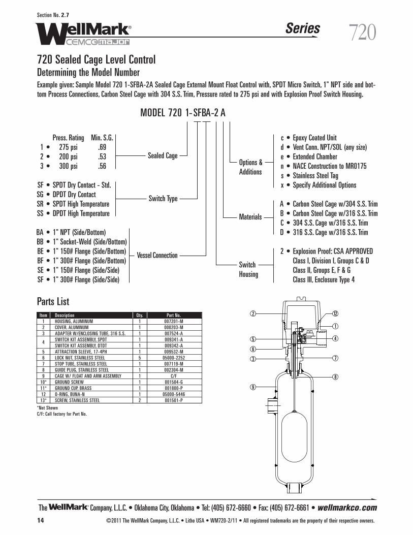
720 Sealed Cage Level ControlDetermining the Model NumberExample given: Sample Model 720 1-SFBA-2A Sealed Cage External Mount Float Control with, SPDT Micro Switch, 1" NPT side and bot-tom Process Connections, Carbon Steel Cage with 304 S.S. Trim, Pressure rated to 275 psi and with Explosion Proof Switch Housing.
c • Epoxy Coated Unitd • Vent Conn. NPT/SOL (any size)e • Extended Chambern • NACE Construction to MR0175s • Stainless Steel Tagx • Specify Additional Options
A • Carbon Steel Cage w/304 S.S. TrimB • Carbon Steel Cage w/316 S.S. TrimC • 304 S.S. Cage w/316 S.S. TrimD • 316 S.S. Cage w/316 S.S. Trim
2 • Explosion Proof: CSA APPROVEDClass I, Division I, Groups C & DClass II, Groups E, F & GClass III, Enclosure Type 4
Press. Rating Min. S.G.1 • 275 psi .692 • 200 psi .533 • 300 psi .56
SF • SPDT Dry Contact - Std.SG • DPDT Dry ContactSR • SPDT High TemperatureSS • DPDT High Temperature
BA • 1" NPT (Side/Bottom)BB • 1" Socket-Weld (Side/Bottom)BE • 1" 150# Flange (Side/Bottom)BF • 1" 300# Flange (Side/Bottom)SE • 1" 150# Flange (Side/Side)SF • 1" 300# Flange (Side/Side)
MODEL 720 1-SFBA-2 A
Switch Type
Sealed CageOptions &Additions
Materials
SwitchHousing
Vessel Connection
2
1
3
45
6
7
8
9
12
Parts ListItem Description Qty. Part No.
1 HOUSING, ALUMINUM 1 007201-M2 COVER, ALUMINUM 1 000203-M3 ADAPTER W/ENCLOSING TUBE, 316 S.S. 1 007524-A
4 SWITCH KIT ASSEMBLY, SPDT 1 009341-ASWITCH KIT ASSEMBLY, DTDT 1 009342-A
5 ATTRACTION SLEEVE, 17-4PH 1 009532-M6 LOCK NUT, STAINLESS STEEL 5 05000-22527 STOP TUBE, STAINLESS STEEL 1 007119-M8 GUIDE PLUG, STAINLESS STEEL 1 002304-M9 CAGE W/ FLOAT AND ARM ASSEMBLY 1 C/F
10* GROUND SCREW 1 001504-G11* GROUND CUP, BRASS 1 001800-P12 O-RING, BUNA-N 1 05000-544613* SCREW, STAINLESS STEEL 2 001501-P
*Not ShownC/F: Call factory for Part No.
The Company, L.L.C. • Oklahoma City, Oklahoma • Tel: (405) 672-6660 • Fax: (405) 672-6661 • wellmarkco.com
Series
©2011 The WellMark Company, L.L.C. • Litho USA • WM730-2/11 • All registered trademarks are the property of their respective owners. 15
730Section No. 2.8
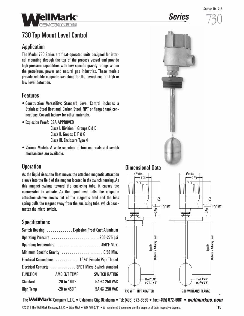
730 Top Mount Level Control
ApplicationThe Model 730 Series are float-operated units designed for inter-nal mounting through the top of the process vessel and providehigh pressure capabilities with low specific gravity ratings withinthe petroleum, power and natural gas industries. These modelsprovide reliable magnetic switching for the lowest cost of high orlow level detection.
Features• Construction Versatility: Standard Level Control includes a
Stainless Steel float and Carbon Steel NPT or flanged tank con-nections. Consult factory for other materials.
• Explosion Proof: CSA APPROVEDClass I, Division I, Groups C & DClass II, Groups E, F & GClass III, Enclosure Type 4
• Various Models: A wide selection of trim materials and switchmechanisms are available.
Operation As the liquid rises, the float moves the attached magnetic attractionsleeve into the field of the magnet located in the switch housing. Asthis magnet swings toward the enclosing tube, it causes themicroswitch to actuate. As the liquid level falls, the magneticattraction sleeve moves out of the magnetic field and the biasspring pulls the magnet away from the enclosing tube, which deac-tuates the micro switch.
SpecificationsSwitch Housing . . . . . . . . . . . . . Explosion Proof Cast Aluminum
Operating Pressure . . . . . . . . . . . . . . . . . . . . . . . . 200-275 psi
Operating Temperature . . . . . . . . . . . . . . . . . . . . . . 450˚F Max.
Minimum Specific Gravity . . . . . . . . . . . . . . . . . . . . . 0.58 Min.
Electrical Connections . . . . . . . . . . . . 1 1/4" Female Pipe Thread
Electrical Contacts . . . . . . . . . . . . . SPDT Micro Switch standard
FUNCTION AMBIENT TEMP SWITCH RATING
Standard -20 to 160˚F 5A @ 250 VAC
High Temp -20 to 450˚F 5A @ 250 VAC
Dimensional Data
Spec
ifyDi
stanc
e To A
ctuati
ng Le
vel
Spec
ifyDi
stanc
e To A
ctuati
ng Le
vel
1 1/4 " NPT 1 1/4 " NPT
730 WITH NPT ADAPTER 730 WITH ANSI FLANGE
Float 3" X 6"or 2 3/4" X 5"
Float 3" X 6"or 2 3/4" X 5"
3 1 /8
3 1 /8
8 1 /8
8 1 /8
4 5/8 Dia.3 7/8
4 5/8 Dia.3 7/8
c • Epoxy Coated Unitd • Dual Stage Controln • NACE Construction to MR0175s • Stainless Steel Tagx • Specify Additional Options
xx • Distance to Actuating Level (inches)
A • C.S. Connection w/304 S.S. TrimB • C.S. Connection w/316 S.S. TrimC • 304 S.S. Connection w/316 S.S. TrimD • 316 S.S. Connection w/316 S.S. Trim
2 • Explosion Proof: CSA APPROVEDClass I, Division I, Groups C & DClass II, Groups E, F & GClass III, Enclosure Type 4
The Company, L.L.C. • Oklahoma City, Oklahoma • Tel: (405) 672-6660 • Fax: (405) 672-6661 • wellmarkco.com
Series
16 ©2011 The WellMark Company, L.L.C. • Litho USA • WM730-2/11 • All registered trademarks are the property of their respective owners.
730Section No. 2.8
730 Top Mount Level Control
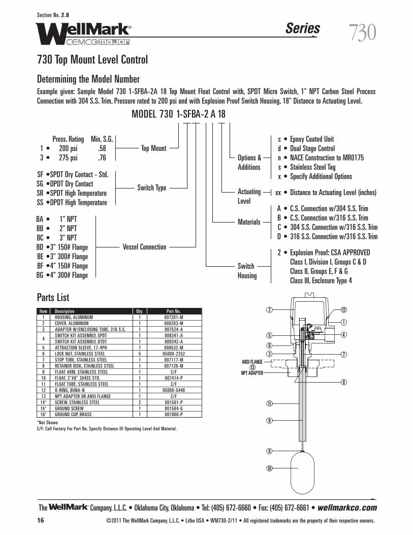
Determining the Model NumberExample given: Sample Model 730 1-SFBA-2A 18 Top Mount Float Control with, SPDT Micro Switch, 1" NPT Carbon Steel ProcessConnection with 304 S.S. Trim, Pressure rated to 200 psi and with Explosion Proof Switch Housing, 18" Distance to Actuating Level.
Press. Rating Min. S.G.1 • 200 psi .583 • 275 psi .76
SF •SPDT Dry Contact - Std.SG •DPDT Dry ContactSR •SPDT High TemperatureSS •DPDT High Temperature
BA • 1" NPTBB • 2" NPTBC • 3" NPTBD •3" 150# FlangeBE •3" 300# FlangeBF •4" 150# FlangeBG •4" 300# Flange
MODEL 730 1-SFBA-2 A 18
Switch Type
Top MountOptions &Additions
ActuatingLevel
Materials
SwitchHousing
Vessel Connection
2
1
3
45
6
6
7
8
9
10
11
12
13ANSI FLANGE
NPT ADAPTER
Parts ListItem Description Qty. Part No.
1 HOUSING, ALUMINUM 1 007201-M2 COVER, ALUMINUM 1 000203-M3 ADAPTER W/ENCLOSING TUBE, 316 S.S. 1 007524-A
4SWITCH KIT ASSEMBLY, SPDT 1 009341-ASWITCH KIT ASSEMBLY, DTDT 1 009342-A
5 ATTRACTION SLEEVE, 17-4PH 1 009532-M6 LOCK NUT, STAINLESS STEEL 5 05000-22527 STOP TUBE, STAINLESS STEEL 1 007117-M8 RETAINER DISK, STAINLESS STEEL 1 007126-M9 FLOAT ARM, STAINLESS STEEL 1 C/F
10 FLOAT, 3"X6" 304SS STD. 1 007414-P11 FLOAT TUBE, STAINLESS STEEL 1 C/F12 O-RING, BUNA-N 1 05000-544613 NPT ADAPTER OR ANSI FLANGE 1 C/F14* SCREW, STAINLESS STEEL 2 001501-P15* GROUND SCREW 1 001504-G16* GROUND CUP, BRASS 1 001800-P
*Not ShownC/F: Call Factory For Part No. Specify Distance Of Operating Level And Material.
The Company, L.L.C. • Oklahoma City, Oklahoma • Tel: (405) 672-6660 • Fax: (405) 672-6661 • wellmarkco.com
Series
©2011 The WellMark Company, L.L.C. • Litho USA • WM740-2/11 • All registered trademarks are the property of their respective owners. 17
740Section No. 2.9
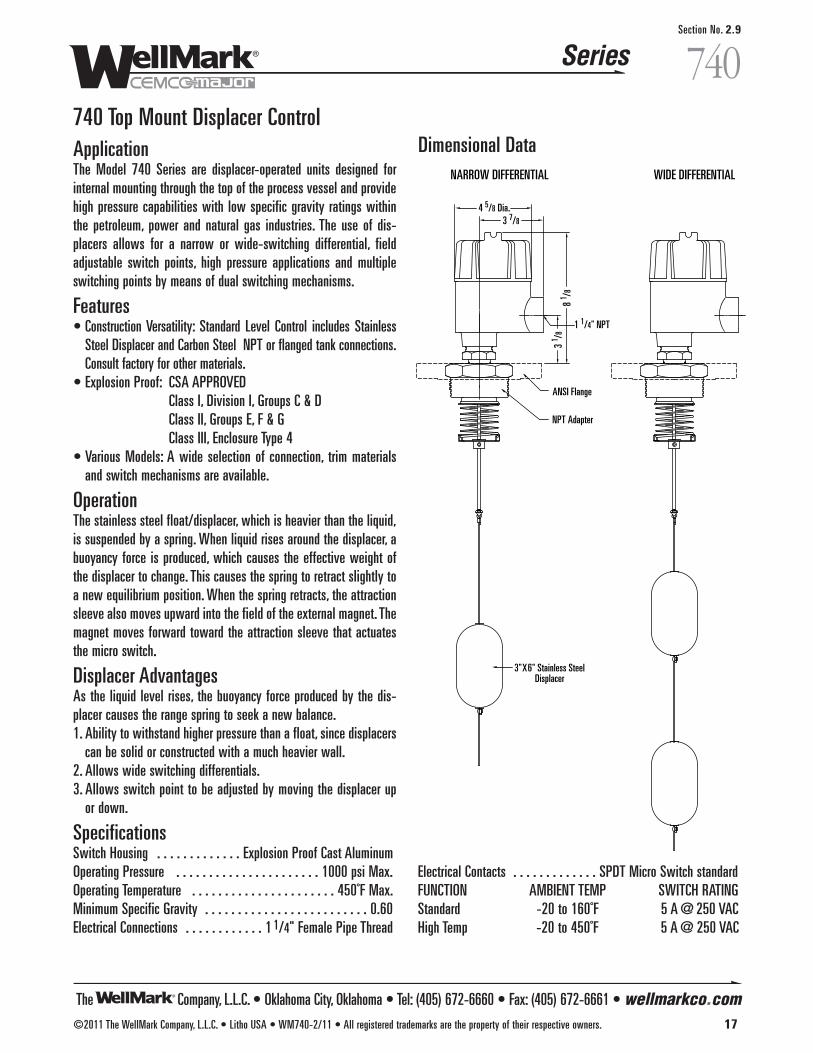
740 Top Mount Displacer ControlApplicationThe Model 740 Series are displacer-operated units designed forinternal mounting through the top of the process vessel and providehigh pressure capabilities with low specific gravity ratings withinthe petroleum, power and natural gas industries. The use of dis-placers allows for a narrow or wide-switching differential, fieldadjustable switch points, high pressure applications and multipleswitching points by means of dual switching mechanisms.
Features• Construction Versatility: Standard Level Control includes Stainless
Steel Displacer and Carbon Steel NPT or flanged tank connections.Consult factory for other materials.
• Explosion Proof: CSA APPROVEDClass I, Division I, Groups C & DClass II, Groups E, F & GClass III, Enclosure Type 4
• Various Models: A wide selection of connection, trim materialsand switch mechanisms are available.
Operation The stainless steel float/displacer, which is heavier than the liquid,is suspended by a spring. When liquid rises around the displacer, abuoyancy force is produced, which causes the effective weight ofthe displacer to change. This causes the spring to retract slightly toa new equilibrium position. When the spring retracts, the attractionsleeve also moves upward into the field of the external magnet. Themagnet moves forward toward the attraction sleeve that actuatesthe micro switch.
Displacer Advantages As the liquid level rises, the buoyancy force produced by the dis-placer causes the range spring to seek a new balance.1. Ability to withstand higher pressure than a float, since displacers
can be solid or constructed with a much heavier wall.2. Allows wide switching differentials.3. Allows switch point to be adjusted by moving the displacer up
or down.
SpecificationsSwitch Housing . . . . . . . . . . . . . Explosion Proof Cast AluminumOperating Pressure . . . . . . . . . . . . . . . . . . . . . . 1000 psi Max. Operating Temperature . . . . . . . . . . . . . . . . . . . . . . 450˚F Max.Minimum Specific Gravity . . . . . . . . . . . . . . . . . . . . . . . . . 0.60 Electrical Connections . . . . . . . . . . . . 1 1/4" Female Pipe Thread
Dimensional Data
1 1/4" NPT
ANSI Flange
NPT Adapter
3"X6" Stainless SteelDisplacer
NARROW DIFFERENTIAL WIDE DIFFERENTIAL
4 5/8 Dia.3 7/8
3 1 /8
8 1 /8
Electrical Contacts . . . . . . . . . . . . . SPDT Micro Switch standardFUNCTION AMBIENT TEMP SWITCH RATING Standard -20 to 160˚F 5 A @ 250 VAC High Temp -20 to 450˚F 5 A @ 250 VAC
The Company, L.L.C. • Oklahoma City, Oklahoma • Tel: (405) 672-6660 • Fax: (405) 672-6661 • wellmarkco.com
Series
18 ©2011 The WellMark Company, L.L.C. • Litho USA • WM740-2/11 • All registered trademarks are the property of their respective owners.
740Section No. 2.9
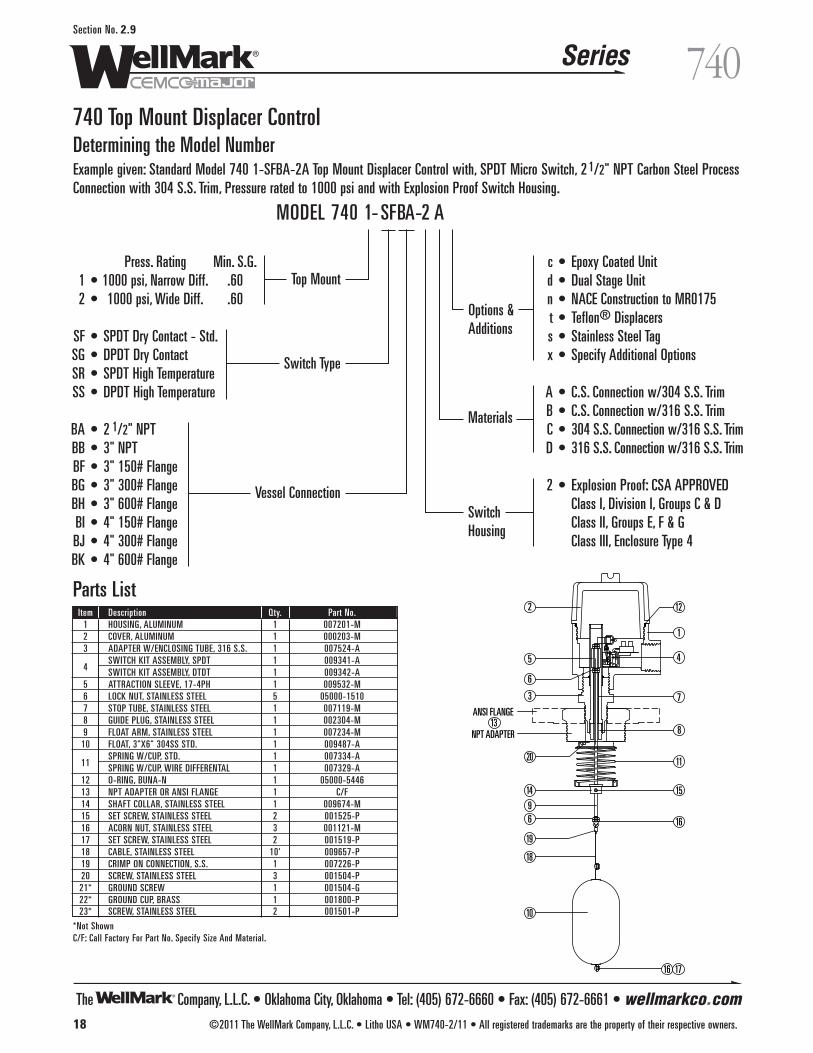
740 Top Mount Displacer ControlDetermining the Model NumberExample given: Standard Model 740 1-SFBA-2A Top Mount Displacer Control with, SPDT Micro Switch, 2 1/2" NPT Carbon Steel ProcessConnection with 304 S.S. Trim, Pressure rated to 1000 psi and with Explosion Proof Switch Housing.
2
1
3
45
6
6
7
8
9
10
12
13ANSI FLANGE
NPT ADAPTER
20
19
18
14
11
15
16
16 17
Parts ListItem Description Qty. Part No.
1 HOUSING, ALUMINUM 1 007201-M2 COVER, ALUMINUM 1 000203-M3 ADAPTER W/ENCLOSING TUBE, 316 S.S. 1 007524-A
4SWITCH KIT ASSEMBLY, SPDT 1 009341-ASWITCH KIT ASSEMBLY, DTDT 1 009342-A
5 ATTRACTION SLEEVE, 17-4PH 1 009532-M6 LOCK NUT, STAINLESS STEEL 5 05000-15107 STOP TUBE, STAINLESS STEEL 1 007119-M8 GUIDE PLUG, STAINLESS STEEL 1 002304-M9 FLOAT ARM, STAINLESS STEEL 1 007234-M
10 FLOAT, 3"X6" 304SS STD. 1 009487-A
11SPRING W/CUP, STD. 1 007334-ASPRING W/CUP, WIRE DIFFERENTAL 1 007329-A
12 O-RING, BUNA-N 1 05000-544613 NPT ADAPTER OR ANSI FLANGE 1 C/F14 SHAFT COLLAR, STAINLESS STEEL 1 009674-M15 SET SCREW, STAINLESS STEEL 2 001525-P16 ACORN NUT, STAINLESS STEEL 3 001121-M17 SET SCREW, STAINLESS STEEL 2 001519-P18 CABLE, STAINLESS STEEL 10' 009657-P19 CRIMP ON CONNECTION, S.S. 1 007226-P20 SCREW, STAINLESS STEEL 3 001504-P21* GROUND SCREW 1 001504-G22* GROUND CUP, BRASS 1 001800-P23* SCREW, STAINLESS STEEL 2 001501-P
*Not ShownC/F: Call Factory For Part No. Specify Size And Material.
c • Epoxy Coated Unitd • Dual Stage Unitn • NACE Construction to MR0175t • Teflon® Displacerss • Stainless Steel Tagx • Specify Additional Options
A • C.S. Connection w/304 S.S. TrimB • C.S. Connection w/316 S.S. TrimC • 304 S.S. Connection w/316 S.S. TrimD • 316 S.S. Connection w/316 S.S. Trim
2 • Explosion Proof: CSA APPROVEDClass I, Division I, Groups C & DClass II, Groups E, F & GClass III, Enclosure Type 4
Press. Rating Min. S.G.1 • 1000 psi, Narrow Diff. .602 • 1000 psi, Wide Diff. .60
SF • SPDT Dry Contact - Std.SG • DPDT Dry ContactSR • SPDT High TemperatureSS • DPDT High Temperature
BA • 2 1/2" NPTBB • 3" NPTBF • 3" 150# FlangeBG • 3" 300# FlangeBH • 3" 600# FlangeBI • 4" 150# FlangeBJ • 4" 300# FlangeBK • 4" 600# Flange
MODEL 740 1- SFBA-2 A
Switch Type
Top Mount
Options &Additions
Materials
SwitchHousing
Vessel Connection
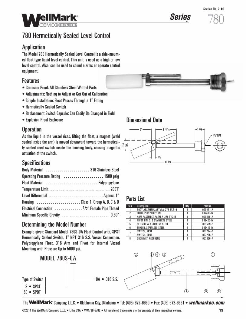
The Company, L.L.C. • Oklahoma City, Oklahoma • Tel: (405) 672-6660 • Fax: (405) 672-6661 • wellmarkco.com
Series
©2011 The WellMark Company, L.L.C. • Litho USA • WM780-9/02 • All registered trademarks are the property of their respective owners. 19
780Section No. 2.10
780 Hermetically Sealed Level Control
ApplicationThe Model 780 Hermetically Sealed Level Control is a side-mount-ed float type liquid level control. This unit is used as a high or lowlevel control. Also, can be used to sound alarms or operate controlequipment.
Features• Corrosion Proof: All Stainless Steel Wetted Parts• Adjustments: Nothing to Adjust or Get Out of Calibration • Simple Installation: Float Passes Through a 1" Fitting• Hermetically Sealed Switch• Replacement Switch Capsule: Can Easily Be Changed in Field • Explosion Proof Enclosure
Operation As the liquid in the vessel rises, lifting the float, a magnet (weldsealed inside the arm) is moved downward toward the hermetical-ly sealed reed switch inside the housing body, causing magneticactuation of the switch.
SpecificationsBody Material . . . . . . . . . . . . . . . . . . . . . . 316 Stainless SteelOperating Pressure Rating . . . . . . . . . . . . . . . . . . . . 1500 psigFloat Material . . . . . . . . . . . . . . . . . . . . . . . . . . Polypropylene Temperature Limit . . . . . . . . . . . . . . . . . . . . . . . . . . . . . . 200˚FLevel Differential . . . . . . . . . . . . . . . . . . . . . . . . . . . Approx. 1"Housing . . . . . . . . . . . . . . . . . . . . . . Class 1, Group A, B, C & DElectrical Connection . . . . . . . . . . . . . . 1/2" Female Pipe ThreadMinimum Specific Gravity . . . . . . . . . . . . . . . . . . . . . . . 0.60"
Determining the Model NumberExample given: Standard Model 780S-0A Float Control with, SPSTHermetically Sealed Switch, 1" NPT 316 S.S. Vessel Connection,Polypropylene Float, 316 Arm and Pivot for Internal VesselMounting with Pressure Up to 5000 psi.
1/2" NPT
10 1/8
3"
1/2
2 13/16 1 3/8
1 1 /
8DI
A.
Dimensional Data
7 8
135 42
6
Parts ListItem Description Qty. Part No.
1 BODY ASSEMBLY, ASTM A-276 TY.316 1 009421-A2 FLOAT, POLYPROPYLENE 1 007400-M3 ARM ASSEMBLY, ASTM A-276 TY.316 1 009419-A4 PIVOT PIN, 316 STAINLESS STEEL 1 009426-M5 SET SCREW, STAINLESS STEEL 1 001539-P6 SPACER, STAINLESS STEEL 1 009418-M
7 SWITCH, SPST 1 007224-PSWITCH, SPDT 1 007225-P
8 GROMMET, NEOPRENE 1 007000-P
0A • 316 S.S.Type of Switch
S • SPSTSC • SPDT
MODEL 780S-0A
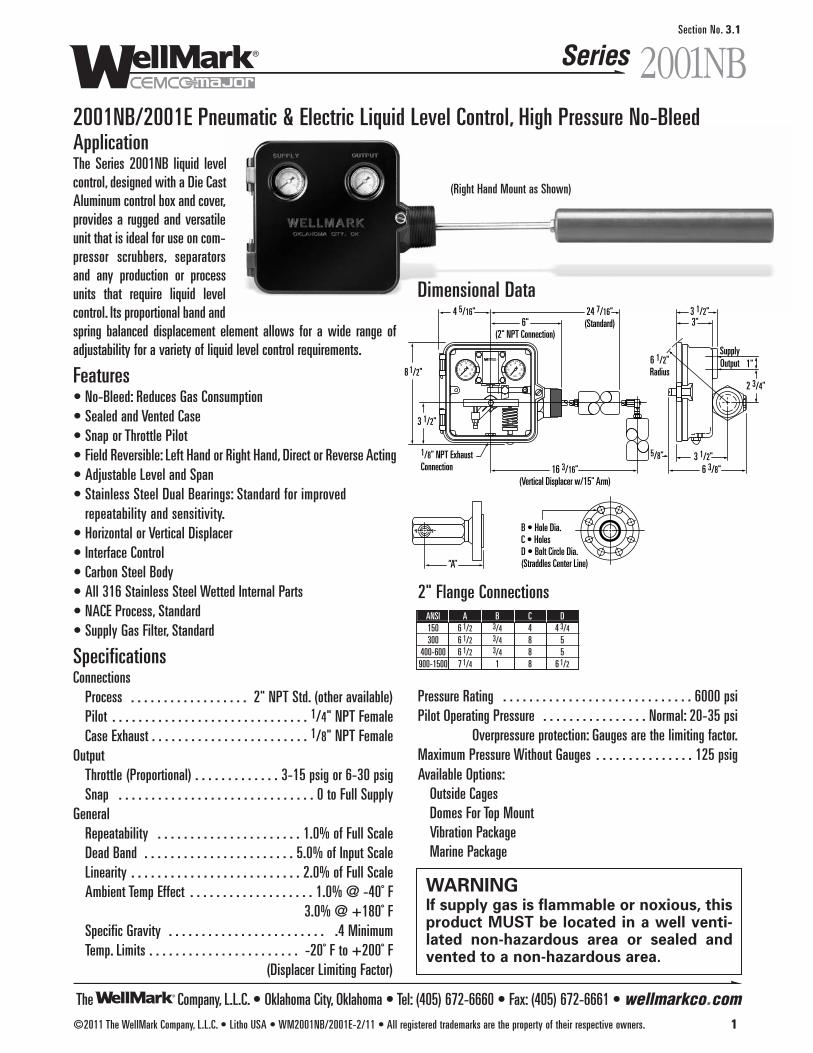
The Company, L.L.C. • Oklahoma City, Oklahoma • Tel: (405) 672-6660 • Fax: (405) 672-6661 • wellmarkco.com
Series 2001NB
©2011 The WellMark Company, L.L.C. • Litho USA • WM2001NB/2001E-2/11 • All registered trademarks are the property of their respective owners. 1
Section No. 3.1
2001NB/2001E Pneumatic & Electric Liquid Level Control, High Pressure No-BleedApplicationThe Series 2001NB liquid levelcontrol, designed with a Die CastAluminum control box and cover,provides a rugged and versatileunit that is ideal for use on com-pressor scrubbers, separatorsand any production or processunits that require liquid levelcontrol. Its proportional band andspring balanced displacement element allows for a wide range ofadjustability for a variety of liquid level control requirements.
Features• No-Bleed: Reduces Gas Consumption• Sealed and Vented Case• Snap or Throttle Pilot• Field Reversible: Left Hand or Right Hand, Direct or Reverse Acting• Adjustable Level and Span• Stainless Steel Dual Bearings: Standard for improved
repeatability and sensitivity.• Horizontal or Vertical Displacer• Interface Control• Carbon Steel Body• All 316 Stainless Steel Wetted Internal Parts• NACE Process, Standard• Supply Gas Filter, Standard
SpecificationsConnections
Process . . . . . . . . . . . . . . . . . . 2" NPT Std. (other available)Pilot . . . . . . . . . . . . . . . . . . . . . . . . . . . . . . 1/4" NPT FemaleCase Exhaust . . . . . . . . . . . . . . . . . . . . . . . . 1/8" NPT Female
OutputThrottle (Proportional) . . . . . . . . . . . . . 3-15 psig or 6-30 psigSnap . . . . . . . . . . . . . . . . . . . . . . . . . . . . . . 0 to Full Supply
GeneralRepeatability . . . . . . . . . . . . . . . . . . . . . . 1.0% of Full ScaleDead Band . . . . . . . . . . . . . . . . . . . . . . . 5.0% of Input ScaleLinearity . . . . . . . . . . . . . . . . . . . . . . . . . . 2.0% of Full ScaleAmbient Temp Effect . . . . . . . . . . . . . . . . . . . 1.0% @ -40˚ F
3.0% @ +180˚ FSpecific Gravity . . . . . . . . . . . . . . . . . . . . . . . . .4 MinimumTemp. Limits . . . . . . . . . . . . . . . . . . . . . . . -20˚ F to +200˚ F
(Displacer Limiting Factor)
2 3/4"
3 1/2"
6 1/2"Radius
3"
SupplyOutput 1"
3 1/2"5/8"6 3/8"
1/8" NPT ExhaustConnection 16 3/16"
(Vertical Displacer w/15" Arm)
“A”
B • Hole Dia.C • HolesD • Bolt Circle Dia.(Straddles Center Line)
6"(2" NPT Connection)
24 7/16"(Standard)
4 5/16"
8 1/2"
3 1/2"
SUPPLY OUTPUT
0 30
255
1015
20
0 30
255
1015
20
Pressure Rating . . . . . . . . . . . . . . . . . . . . . . . . . . . . . 6000 psiPilot Operating Pressure . . . . . . . . . . . . . . . . Normal: 20-35 psi
Overpressure protection: Gauges are the limiting factor.Maximum Pressure Without Gauges . . . . . . . . . . . . . . . 125 psigAvailable Options:
Outside CagesDomes For Top MountVibration PackageMarine Package
2" Flange ConnectionsANSI A B C D150 6 1/2 3/4 4 4 3/4
300 6 1/2 3/4 8 5400-600 6 1/2 3/4 8 5900-1500 7 1/4 1 8 6 1/2
WARNINGIf supply gas is flammable or noxious, thisproduct MUST be located in a well venti-lated non-hazardous area or sealed andvented to a non-hazardous area.
Dimensional Data
(Right Hand Mount as Shown)
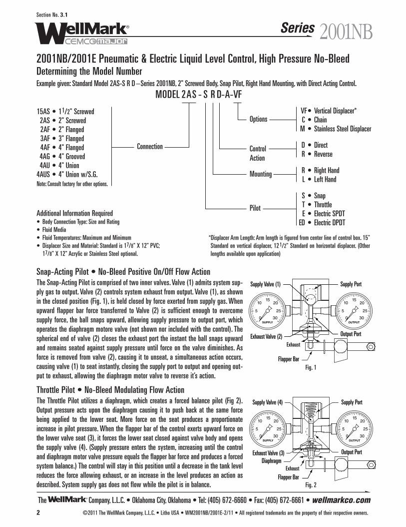
The Company, L.L.C. • Oklahoma City, Oklahoma • Tel: (405) 672-6660 • Fax: (405) 672-6661 • wellmarkco.com
Series
2 ©2011 The WellMark Company, L.L.C. • Litho USA • WM2001NB/2001E-2/11 • All registered trademarks are the property of their respective owners.
2001NBSection No. 3.1
2001NB/2001E Pneumatic & Electric Liquid Level Control, High Pressure No-BleedDetermining the Model NumberExample given: Standard Model 2AS-S R D –Series 2001NB, 2" Screwed Body, Snap Pilot, Right Hand Mounting, with Direct Acting Control.
VF• Vertical Displacer*C • Chain
M • Stainless Steel Displacer
D • DirectR • Reverse
R • Right HandL • Left Hand
S • SnapT • ThrottleE • Electric SPDT
ED • Electric DPDT
15AS • 11/2" Screwed2AS • 2" Screwed2AF • 2" Flanged3AF • 3" Flanged4AF • 4" Flanged4AG • 4" Grooved4AU • 4" Union
4AUS • 4" Union w/S.G.Note: Consult factory for other options.
MODEL 2AS - S R D-A-VF
Connection
Pilot
Mounting
ControlAction
Options
Additional Information Required• Body Connection Type: Size and Rating• Fluid Media• Fluid Temperatures: Maximum and Minimum• Displacer Size and Material: Standard is 17/8" X 12" PVC;
17/8" X 12" Acrylic or Stainless Steel optional.
Snap-Acting Pilot • No-Bleed Positive On/Off Flow ActionThe Snap-Acting Pilot is comprised of two inner valves. Valve (1) admits system sup-ply gas to output. Valve (2) controls system exhaust from output. Valve (1), as shownin the closed position (Fig. 1), is held closed by force exerted from supply gas. Whenupward flapper bar force transferred to Valve (2) is sufficient enough to overcomesupply force, the ball snaps upward, allowing supply pressure to output port, whichoperates the diaphragm motore valve (not shown nor included with the control). Thespherical end of valve (2) closes the exhaust port the instant the ball snaps upwardand remains seated against supply pressure until force on the valve diminishes. Asforce is removed from valve (2), causing it to unseat, a simultaneous action occurs,causing valve (1) to seat instantly, closing the supply port to output and opening out-put to exhaust, allowing the diaphragm motor valve to reverse it’s action.
Throttle Pilot • No-Bleed Modulating Flow ActionThe Throttle Pilot utilizes a diaphragm, which creates a forced balance pilot (Fig 2).Output pressure acts upon the diaphragm causing it to push back at the same forcebeing applied to the lower seat. More force on the seat produces a proportionateincrease in pilot pressure. When the flapper bar of the control exerts upward force onthe lower valve seat (3), it forces the lower seat closed against valve body and opensthe supply valve (4). (Supply pressure enters the system, increasing until the controland diaphragm motor valve pressure equals the flapper bar force and produces a forcedsystem balance.) The control will stay in this position until a decrease in the tank levelreduces the force allowing exhaust, or an increase in the level produces an action asdescribed. System supply gas does not flow while the pilot is in balance.
*Displacer Arm Length: Arm length is figured from center line of control box. 15"Standard on vertical displacer, 12 1/2" Standard on horizontal displacer. (Otherlengths available upon application)
SUPPLY0 30
255
1015
20
0 30
255
1015
20
Flapper Bar
Exhaust
Supply Valve (1)
Exhaust Valve (2)
Supply Port
Output Port
OUTPUT
SUPPLY0 30
255
20
0 30
255
20
OUTPUT
Flapper BarExhaust
Diaphragm
Supply Valve (4)
Exhaust Valve (3)
Supply Port
Output Port
1015 15
10
Fig. 1
Fig. 2

The Company, L.L.C. • Oklahoma City, Oklahoma • Tel: (405) 672-6660 • Fax: (405) 672-6661 • wellmarkco.com
Series 2001NB
©2011 The WellMark Company, L.L.C. • Litho USA • WM2001NB/2001E-2/11 • All registered trademarks are the property of their respective owners. 3
Section No. 3.1
2001NB/2001E Pneumatic & Electric Liquid Level Control, High Pressure No-Bleed
SUPPLY OUTPUT
0 30
255
1015
20
0 30
255
1015
20
28 2324
2541
30 31 32
27
3317
1340
18141216
37382323635
192915212226
20
44
3
105
41
34
39
9
43
42
8
11 6 7
Vertical Displacer Assembly
Horizontal DisplacerAssembly
Parts ListItem Description Qty. Part No.
1 CONTROL BOX, DIE CAST ALUMINUM 1 05012-48412 COVER, DIE CAST ALUMINUM 1 05012-4834*3 BOX SEAL, NEOPRENE 1 06000-5097
*4 SNAP PILOT ASSY., ALUMINUM & 316 S.S. 1 06500-5304THROTTLE PILOT ASSY., ALUMINUM & 316 S.S. 1 06500-5387
5 BODY, ASTM A-108GR. 1018 1 05011-45606 PIVOT SHAFT, ASTM A-276 TY.316 1 05011-4511*7 O-RING, VITON® 2 05000-0769*8 BACK UP RING, TEFLON® 2 06000-11799 SHAFT RETAINER, ASTM A-276 TY.316 2 05012-9389
*10 O-RING, VITON® 2 05000-115511 SPACER, ASTM A-276 TY. 316 1 05011-449512 CAP SCREW, 18-8 S.S. 2 05000-557813 CAP SCREW, 18-8 S.S. 1 05000-545314 ADJUSTING BAR, ALUMINUM 1 05011-443815 CAP SCREW, 18-8 S.S. 2 05000-252616 TORQUE BAR, ALUMINUM 1 05011-454517 ADJ. SCREW, ASTM A-276 TY.316 1 05011-453718 JAM NUT, 18-8 S.S. 1 05000-255919 STUD, 18-8 S.S. 1 05011-455220 LOWER SPRING GUIDE, ALUMINUM 1 05011-4529
SPRING, ASTM A-313, STANDARD (YELLOW) 1 06000-415721 SPRING, ASTM A-313, LIGHT (GREEN) 1 06000-3985
SPRING, ASTM A-313, HEAVY (RED) 1 06000-900822 UPPER SPRING GUIDE, ALUMINUM 1 05011-447923 STUD, FLAPPER BAR, ASTM A-276 TY.316 2 05012-9371
*Recommended Spare Part
Repair KitsBAR FLAPPER KIT 1 03500-1882NUT 1 05000-2567RETAINER RING 1 06000-1385FLAPPER BAR 1 05011-4404CLAMP KIT 1 03500-1890CAP SCREW 4 05000-5313CLAMP 1 05012-6325SHAFT RETAINER KIT 1 06500-5601SHAFT RETAINER 1 05012-9389BEARING 1 06000-7552TOLERANCE RING 1 06000-7560STD. FULCRUM KIT 1 03500-1898FULCRUM 1 05011-4412THUMB SCREW 1 06500-5429BAR ADJUSTING LEVEL KIT 1 03500-1906BAR ADJUSTING LEVEL 1 05011-4438JAM NUT 1 05000-2559CAP SCREW 2 05000-2526ADJUSTING SCREW 1 05011-4537
TORQUE BAR KIT 1 03500-1914STD. TORQUE BAR 1 05011-4545LOCK NUT 1 05000-2567SENSITIVITY SCALE 1 10739SNAP PILOT KIT 1 03500-1114FILTER 1 06000-1526GASKET 1 06000-1484
PIN W/RETAINER RING 1 05011-45031 06000-1393
BALL 1 06000-1906THROTTLE PILOT KIT 1 03500-1163FILTER 1 06000-1526GASKET 1 06000-1484DIAPHRAGM 1 06000-1559SEAT 1 05011-4594FLAT WASHER-NYLON 1 05011-4602JAM NUT 1 05000-2559PEANUT 1 05011-4586SPRING 1 06000-1567
Model and Part NumbersModel No. Displacer Orientation Part No.2AS-SLD-A HORIZONTAL-STANDARD 03051-08502AS-SRD-A HORIZONTAL-STANDARD 03051-08002AS-TLD HORIZONTAL-STANDARD 03051-08922AS-TRD HORIZONTAL-STANDARD 03051-09182AS-SLD-VF VERTICAL DISPLACER 03051-08682AS-SRD-VF VERTICAL DISPLACER 03051-08762AS-TLD-VF VERTICAL DISPLACER 03051-09002AS-TRD-VF VERTICAL DISPLACER 03051-0926
Charts indicate the Kit and Part Descriptions, the Quantities required and the Part Number for ordering.
Item Description Qty. Part No.24 FLAPPER BAR, ASTM A-276 TY.316 1 05011-4404 25 TRU-ARC RING, PH 15-7 MO 1 06000-138526 FULCRUM, ALUMINUM 1 05011-441227 THUMB SCREW, S.S./PLASTIC 1 06500-542928 NY-LOC NUT, STAINLESS STEEL 2 05000-256729 ACORN NUT, STAINLESS STEEL 1 05000-2575
30 DISPLACER ARM, STD., ASTM A-276 TY.316 1 06000-1534DISPLACER ARM, VF, ASTM A-276 TY.316 1 05011-9296
31 DISPLACER BUSHING, ASTM A-276 TY.316 1 06000-510532 DISPLACER, PVC 1 05012-356133 HINGE PIN, STEEL PLATED 2 06000-7537*34 GASKET, NEOPRENE 1 06000-481935 CAP SCREW, 18-8 S.S. 4 05000-531336 PILOT CLAMP, 304 S.S. 1 05012-632537 PANEL SCREW, STAINLESS STEEL 1 06000-115338 RETAINER, STAINLESS STEEL 1 06000-267239 SERIAL TAG, ALUMINUM 1 06000-1922*40 THREAD SEAL, STEEL/BUNA N 1 06000-0395*41 GASKET, VITON® 1 1001642 BEARING, STAINLESS STEEL 2 06000-755243 TOLERANCE RING, STAINLESS STEEL 2 06000-756044 ADAPTER V.D. ASSY., ASTM A-276 TY.316 1 06500-435045 COVER GLASS, LEXAN (NOT SHOWN) 2 1091646 COVER GLASS PLATE, S.S. (NOT SHOWN) 2 1091547 COVER GLASS GASKET, NEOPRENE (NOT SHOWN) 2 1091748 SCREW, PLATED STEEL (NOT SHOWN) 8 001501P
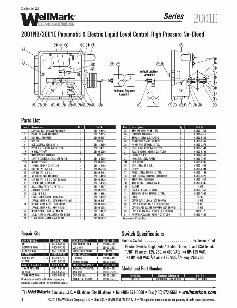
The Company, L.L.C. • Oklahoma City, Oklahoma • Tel: (405) 672-6660 • Fax: (405) 672-6661 • wellmarkco.com
Series
4 ©2011 The WellMark Company, L.L.C. • Litho USA • WM2001NB/2001E-2/11 • All registered trademarks are the property of their respective owners.
2001ESection No. 3.1
2001NB/2001E Pneumatic & Electric Liquid Level Control, High Pressure No-Bleed
3336 35
27
26
103442524
23
16 12 18 17 14 28 29 19 20 21 22 28 30 2 3 13 40 1 11 5
9
8
43
6
42
7
103837 39
44
31 32
51 41
Vertical Displacer Assembly
Horizontal DisplacerAssembly
Parts ListItem Description Qty. Part No.
1 CONTROL BOX, DIE CAST ALUMINUM 1 05012-48432 COVER, DIE CAST ALUMINUM 1 05012-4834*3 BOX SEAL, NEOPRENE 1 06000-50974 SWITCH 1 100065 BODY, ASTM A-108GR. 1018 1 05011-45606 PIVOT SHAFT, ASTM A-276 TY.316 1 05011-4511*7 O-RING, VITON® 2 05000-0769*8 BACK UP RING, TEFLON® 2 110879 SHAFT RETAINER, ASTM A-276 TY.316 2 05012-9389
*10 O-RING, VITON® 3 05000-115511 SPACER, ASTM A-276 TY. 316 1 05011-449512 CAP SCREW, 18-8 S.S. 2 05000-557813 CAP SCREW, 18-8 S.S. 1 05000-545314 ADJUSTING BAR, ALUMINUM 1 05011-443815 CAP SCREW, 18-8 S.S. (NOT SHOWN) 2 05000-252616 TORQUE BAR, ALUMINUM 1 05011-454517 ADJ. SCREW, ASTM A-276 TY.316 1 05011-453718 JAM NUT, 18-8 S.S. 1 05000-255919 STUD, 18-8 S.S. 1 05011-455220 LOWER SPRING GUIDE, ALUMINUM 1 05011-4529
SPRING, ASTM A-313, STANDARD (YELLOW) 1 06000-415721 SPRING, ASTM A-313, LIGHT (GREEN) 1 06000-3985
SPRING, ASTM A-313, HEAVY (RED) 1 06000-900822 UPPER SPRING GUIDE, ALUMINUM 1 05011-447923 STUD, FLAPPER BAR, ASTM A-276 TY.316 2 05012-937124 FLAPPER BAR, ASTM A-276 TY.316 1 06500-7233
Repair KitsBAR FLAPPER KIT 1 03500-1882NUT 1 05000-2567RETAINER RING 1 06000-1385FLAPPER BAR 1 05011-4404CLAMP KIT 1 03500-1890CAP SCREW 4 05000-5313CLAMP 1 05012-6325SHAFT RETAINER KIT 1 06500-5601SHAFT RETAINER 1 05012-9389BEARING 1 06000-7552TOLERANCE RING 1 06000-7560
TORQUE BAR KIT 1 03500-1914STD. TORQUE BAR 1 05011-4545LOCK NUT 1 05000-2567SENSITIVITY SCALE 1 10739STD. FULCRUM KIT 1 03500-1898FULCRUM 1 05011-4412THUMB SCREW 1 06500-5429BAR ADJUSTING LEVEL KIT 1 03500-1906BAR ADJUSTING LEVEL 1 05011-4438JAM NUT 1 05000-2559CAP SCREW 2 05000-2526ADJUSTING SCREW 1 05011-4537
Model and Part NumberModel No. Displacer Orientation Part No.2AS-ERD HORIZONTAL-STANDARD 03051-9000Charts indicate the Kit and Part Descriptions, the
Quantities required and the Part Number for ordering.
Item Description Qty. Part No.25 TRU-ARC RING, PH 15-7 MO 1 06000-138526 FULCRUM, ALUMINUM 1 05011-441227 THUMB SCREW, S.S./PLASTIC 1 06500-542928 NY-LOC NUT, STAINLESS STEEL 2 05000-256729 ACORN NUT, STAINLESS STEEL 1 05000-257530 FLOAT ARM, ASTM A-276 TY.316 1 06000-153431 FLOAT BUSHING, ASTM A-276 TY.316 1 06000-510532 DISPLACER, PVC 1 05012-356133 HINGE PIN, STEEL PLATED 2 06000-7537*34 PIPE NIPPLE 1 06000-838635 CAP SCREW, 18-8 S.S. 2 05000-158636 ELBOW 1 06000-839437 PANEL SCREW, STAINLESS STEEL 1 06000-115338 PANEL SCREW RETAINER, STAINLESS STEEL 1 06000-267239 SERIAL TAG, ALUMINUM 1 06000-1922*40 THREAD SEAL, STEEL/BUNA N 1 06000-0395*41 GASKET 1 1001642 BEARING, STAINLESS STEEL 2 06000-755243 TOLERANCE RING, STAINLESS STEEL 2 06000-756044 PLUG 2 1014945 COVER GLASS, LEXAN (NOT SHOWN) 2 1091646 COVER GLASS PLATE, S.S. (NOT SHOWN) 2 1091547 COVER GLASS GASKET, NEOPRENE (NOT SHOWN) 2 1091748 COVER SCREW, PLATED STEEL (NOT SHOWN) 8 001501-P51 ADAPTER V.D. ASSY., ASTM A-276 TY.316 1 06500-4350
*Recommended Spare Part
Switch SpecificationsElectric Switch . . . . . . . . . . . . . . . . . . . . . . . . . Explosion Proof
Electric Switch, Single Pole / Double Throw, UL and CSA listed: "L96" 15 amps, 125, 250, or 480 VAC; 1/8 HP-125 VAC, 1/4 HP-250 VAC, 1/2 amp-125 VDC, 1/4 amp-250 VDC
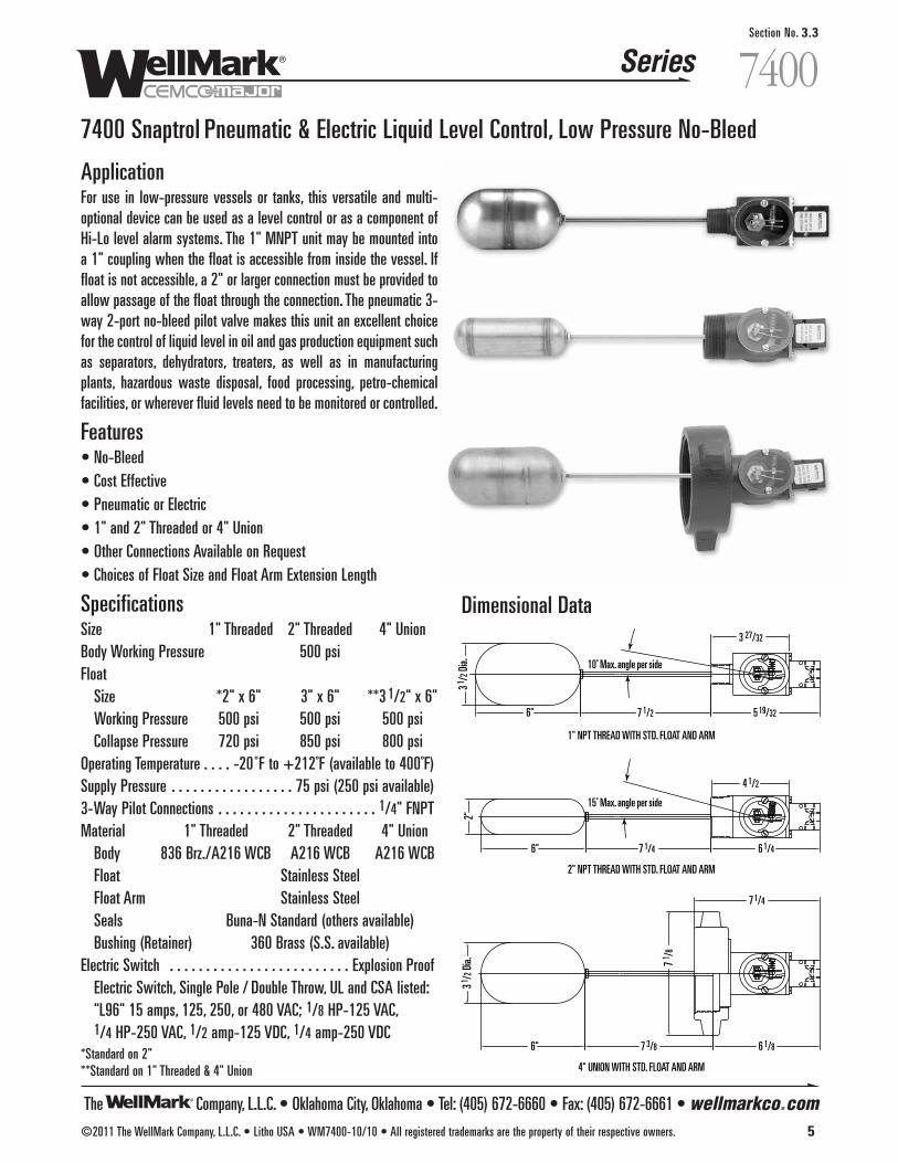
The Company, L.L.C. • Oklahoma City, Oklahoma • Tel: (405) 672-6660 • Fax: (405) 672-6661 • wellmarkco.com
Series
©2011 The WellMark Company, L.L.C. • Litho USA • WM7400-10/10 • All registered trademarks are the property of their respective owners. 5
7400Section No. 3.3
7400 Snaptrol Pneumatic & Electric Liquid Level Control, Low Pressure No-Bleed
ApplicationFor use in low-pressure vessels or tanks, this versatile and multi-optional device can be used as a level control or as a component ofHi-Lo level alarm systems. The 1" MNPT unit may be mounted intoa 1" coupling when the float is accessible from inside the vessel. Iffloat is not accessible, a 2" or larger connection must be provided toallow passage of the float through the connection. The pneumatic 3-way 2-port no-bleed pilot valve makes this unit an excellent choicefor the control of liquid level in oil and gas production equipment suchas separators, dehydrators, treaters, as well as in manufacturingplants, hazardous waste disposal, food processing, petro-chemicalfacilities, or wherever fluid levels need to be monitored or controlled.
Features• No-Bleed• Cost Effective• Pneumatic or Electric• 1" and 2" Threaded or 4" Union• Other Connections Available on Request• Choices of Float Size and Float Arm Extension Length
SpecificationsSize 1" Threaded 2" Threaded 4" UnionBody Working Pressure 500 psiFloat
Size *2" x 6" 3" x 6" **3 1/2" x 6"Working Pressure 500 psi 500 psi 500 psiCollapse Pressure 720 psi 850 psi 800 psi
Operating Temperature . . . . -20 ˚F to +212˚F (available to 400˚F)Supply Pressure . . . . . . . . . . . . . . . . . 75 psi (250 psi available)3-Way Pilot Connections . . . . . . . . . . . . . . . . . . . . . . 1/4" FNPTMaterial 1" Threaded 2" Threaded 4" Union
Body 836 Brz./A216 WCB A216 WCB A216 WCBFloat Stainless SteelFloat Arm Stainless SteelSeals Buna-N Standard (others available)Bushing (Retainer) 360 Brass (S.S. available)
Electric Switch . . . . . . . . . . . . . . . . . . . . . . . . . Explosion ProofElectric Switch, Single Pole / Double Throw, UL and CSA listed: "L96" 15 amps, 125, 250, or 480 VAC; 1/8 HP-125 VAC, 1/4 HP-250 VAC, 1/2 amp-125 VDC, 1/4 amp-250 VDC
*Standard on 2"**Standard on 1" Threaded & 4" Union
Dimensional Data
4 1/2
6 1/47 1/4
15˚ Max. angle per side
10˚ Max. angle per side
6"
2"
7 1 /8
7 1/4
6 1/87 3/86"
3 1 /2 D
ia.
5 19/327 1/2
3 1 /2 D
ia.
6"
1" NPT THREAD WITH STD. FLOAT AND ARM
2" NPT THREAD WITH STD. FLOAT AND ARM
4" UNION WITH STD. FLOAT AND ARM
3 27/32
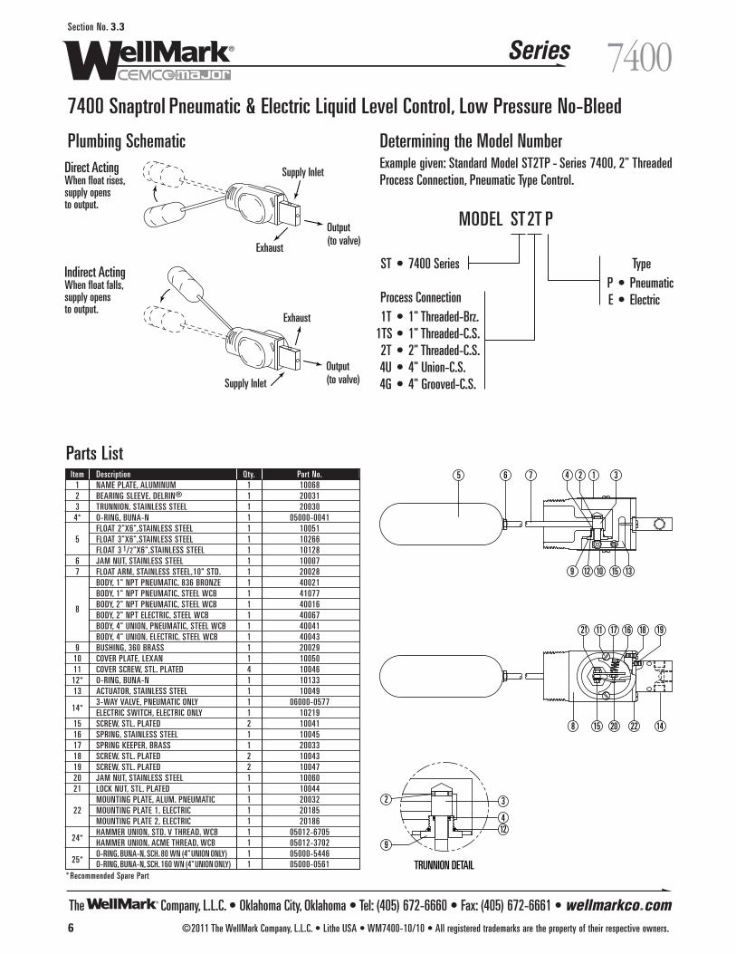
The Company, L.L.C. • Oklahoma City, Oklahoma • Tel: (405) 672-6660 • Fax: (405) 672-6661 • wellmarkco.com
Series
6 ©2011 The WellMark Company, L.L.C. • Litho USA • WM7400-10/10 • All registered trademarks are the property of their respective owners.
7400Section No. 3.3
7400 Snaptrol Pneumatic & Electric Liquid Level Control, Low Pressure No-Bleed
21 17 16 18
1415 20 22
5 6 7
8
12 3
10
11
13159 12
4
19
TRUNNION DETAIL
9
124
32
Parts ListItem Description Qty. Part No.
1 NAME PLATE, ALUMINUM 1 100682 BEARING SLEEVE, DELRIN® 1 200313 TRUNNION, STAINLESS STEEL 1 200304* O-RING, BUNA-N 1 05000-0041
FLOAT 2"X6",STAINLESS STEEL 1 100515 FLOAT 3"X6",STAINLESS STEEL 1 10266
FLOAT 3 1/2"X6",STAINLESS STEEL 1 101286 JAM NUT, STAINLESS STEEL 1 100077 FLOAT ARM, STAINLESS STEEL,10" STD. 1 20028
BODY, 1" NPT PNEUMATIC, 836 BRONZE 1 40021BODY, 1" NPT PNEUMATIC, STEEL WCB 1 41077
8 BODY, 2" NPT PNEUMATIC, STEEL WCB 1 40016BODY, 2" NPT ELECTRIC, STEEL WCB 1 40067BODY, 4" UNION, PNEUMATIC, STEEL WCB 1 40041BODY, 4" UNION, ELECTRIC, STEEL WCB 1 40043
9 BUSHING, 360 BRASS 1 2002910 COVER PLATE, LEXAN 1 1005011 COVER SCREW, STL. PLATED 4 1004612* O-RING, BUNA-N 1 1013313 ACTUATOR, STAINLESS STEEL 1 10049
14*3-WAY VALVE, PNEUMATIC ONLY 1 06000-0577ELECTRIC SWITCH, ELECTRIC ONLY 1 10219
15 SCREW, STL. PLATED 2 1004116 SPRING, STAINLESS STEEL 1 1004517 SPRING KEEPER, BRASS 1 2003318 SCREW, STL. PLATED 2 1004319 SCREW, STL. PLATED 2 1004720 JAM NUT, STAINLESS STEEL 1 1006021 LOCK NUT, STL. PLATED 1 10044
MOUNTING PLATE, ALUM. PNEUMATIC 1 2003222 MOUNTING PLATE 1, ELECTRIC 1 20185
MOUNTING PLATE 2, ELECTRIC 1 20186HAMMER UNION, STD. V THREAD, WCB 1 05012-6705
24* HAMMER UNION, ACME THREAD, WCB 1 05012-3702
25*O-RING, BUNA-N, SCH.80 WN (4"UNION ONLY) 1 05000-5446O-RING, BUNA-N, SCH.160 WN (4"UNION ONLY) 1 05000-0561
* Recommended Spare Part
Determining the Model NumberExample given: Standard Model ST2TP - Series 7400, 2" ThreadedProcess Connection, Pneumatic Type Control.
Plumbing Schematic
TypeP • PneumaticE • Electric
ST • 7400 Series
Process Connection1T • 1" Threaded-Brz.
1TS • 1" Threaded-C.S.2T • 2" Threaded-C.S.4U • 4" Union-C.S.4G • 4" Grooved-C.S.
MODEL ST2T P
Direct ActingWhen float rises, supply opens to output.
Indirect ActingWhen float falls, supply opens to output.
Supply Inlet
Supply Inlet
Exhaust
Exhaust
Output(to valve)
Output(to valve)

The Company, L.L.C. • Oklahoma City, Oklahoma • Tel: (405) 672-6660 • Fax: (405) 672-6661 • wellmarkco.com
Series
1
3
2
Diaphragm Motor Valve
1800-M
Figure 1
1800-E
Figure 2
Motor
Horn
Signal Light
Relay
©2011 The WellMark Company, L.L.C. • Litho USA • WM1800-6/09 • All registered trademarks are the property of their respective owners. 7
1800Section No. 3.4
1800 Pneumatic & Electric Liquid Level Control, Low Pressure No-Bleed
ApplicationThe WellMark 1800 Liquid Level Control offers design simplicity,easy installation, adjustment, and reliable liquid-level monitoring.The Model 1800 can be equipped with a snap action 3-way 2-portvalve (1800M) or an electrical contact switch (1800E).The Model 1800 is actuated by movable arms that permit the con-trol range to be adjusted easily and accurately set to the rangedesired. With the liquid level below the float, the 3-way 2-portvalve, or micro switch, will be in low level position and will remainthere until the float rises to the pre-set high level. The 3-way 2-portvalve, or micro switch, reverses positions as the float rises or dropsthrough the pre-set level.The 1800 Liquid Level Control can be used in oil and gas process-ing, manufacturing plants, hazardous waste disposal, food process-ing, petro-chemical facilities, or wherever fluid levels need to bemonitored or controlled.
Installation The WellMark Model 1800 is available with various standard pipeclosures such as ANSI flanges and grooved connections.
Dimensional Data
4 1/2 Pneumatic
5" Electric2 7/8
4"-150 Flanged Connection
4" Grooved Connection
16" Std. Float & Arm
60˚ Maximum Range
30˚ Max. Limit
Pneumatic Control Valve PipingThe WellMark Model 1800 Pneumatic Level Control is equippedwith a 3-way 2-port valve with three 1/4" NPT ports. The 3-way2-port valve has a standard working pressure of 100 psi.The connections to the ports depend on the control action desired.Port positions are shown below. Reference figure 1.
The WellMark Model 1800 Electric Level Control provides electricalcontact switch closure for alarm or control functions. Reference figure 2.
Explosion ProofElectric Switch, SPDTUL and CSA listed: “L96” 15 amps, 125, 250, or480 VAC; 1/8 HP-125 VAC, 1/4 HP-250 VAC1/2 amp-125 VDC, 1/4 amp-250 VDC
With Float At Low LevelPORT 1 CLOSED TO 2
PORT 2 COMMONPORT 3 OPEN TO 2
With Float At High LevelPORT 1 OPEN TO 2PORT 2 COMMON
PORT 3 CLOSED TO 2
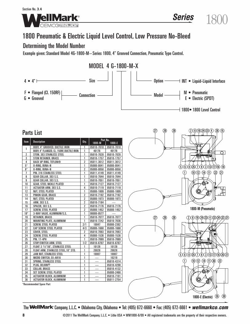
The Company, L.L.C. • Oklahoma City, Oklahoma • Tel: (405) 672-6660 • Fax: (405) 672-6661 • wellmarkco.com
Series
8 ©2011 The WellMark Company, L.L.C. • Litho USA • WM1800-6/09 • All registered trademarks are the property of their respective owners.
1800Section No. 3.4
1800 Pneumatic & Electric Liquid Level Control, Low Pressure No-Bleed
1 10 12 1114
17 16 18
22 21
5 6 258 7 9 13
2 6 19 24 23 4 26 15
3
27 2829
29 2827
3 26
423241962
13978 2565
22
1617
14 1112101
21
3035
36
32 313433
1800-M (Pneumatic)
1800-E (Electric)
Parts List
Determining the Model NumberExample given: Standard Model 4G-1800-M– Series 1800, 4" Grooved Connection, Pneumatic Type Control.
INT • Liquid-Liquid Interface
M • PneumaticE • Electric (SPDT)
1800• 1800 Level Control
4 • 4"
F • Flanged (Cl. 150RF)G • Grooved
MODEL 4 G-1800-M-X
Item Description Qty. Part No.1800-M 1800-E
1 BODY, 4" GROOVED, DUCTILE IRON 1 05010-7010 05010-7010BODY, 4" FLANGED, CL. 150RF, DUCTILE IRON 1 40176 40176
2 STEM, 303 STAINLESS STEEL 1 05010-7028 05010-70283 STEM RETAINER, BRASS 1 05010-1757 05010-17574 BACK UP RING, TEFLON® 2 05011-3612 05011-36125* O-RING, BUNA-N 1 05000-0041 05000-00416* O-RING, BUNA-N 2 05000-0058 05000-00587 PIN, 316 STAINLESS STEEL 1 05011-4149 05011-41498 GEAR COLLAR, 303 S.S. 1 05010-7044 05010-70449 GEAR COLLAR, 303 S.S. 1 05010-7051 05010-7051
10 GEAR, STEEL NICKLE PLATED 1 05010-7127 05010-712711 ACTUATOR ARM, 303 S.S. 4 05010-7119 05010-711912 NUT, STEEL PLATED 1 05000-1809 05000-180913 PINION GEAR, BRASS 2 05010-7192 05010-719214 NUT, STEEL PLATED 2 05000-1973 05000-197315 ARM, 303 S.S. 2 05010-7184 —16 SPACER, 303 S.S. 2 05010-7176 05010-717617 SCREW, STEEL PLATED 2 05000-1452 05000-145218* 3-WAY VALVE, ALUMINUM/S.S. 1 06000-0577 —19 RETAINER, BRASS 1 05010-7077 05010-707720 MOUNTING PLATE, ALUMINUM 1 05010-7242 05010-703621 SCREW, STEEL PLATED 2/1 10047 05000-230222 CAP SCREW, STEEL PLATED 4/3 05000-1668 05000-166823 COVER, STEEL 2 05010-7093 05010-709324 SCREW, STEEL PLATED 4 05000-1536 05000-153625 PIN, 17-4PH 1 05010-7069 05010-706926 STOP/SWITCH ARM, STEEL 1/2 05010-6707 05010-670727 FLOAT 3 1/2"X6", STAINLESS STEEL 1 10128 1012828 FLOAT ARM, STAINLESS STEEL,10" STD. 1 20028 2002829 JAM NUT, STAINLESS STEEL 1 10007 1000730 MICRO SWITCH, EX-AR16 1 — 1021931 SPRING, STAINLESS STEEL 1 — 05010-431432 PLUG, DELRIN® 1 — 05010-429833 COLLAR, BRASS 1 — 05010-413234 SET SCREW, STEEL PLATED 1 — 05000-246835 ACTUATOR BLOCK, ALUMINUM 1 — 05010-710136 ACTUATOR BLOCK, ALUMINUM 1 — 05011-2754
*Recommended Spare Part
Size Option
ModelConnection

The Company, L.L.C. • Oklahoma City, Oklahoma • Tel: (405) 672-6660 • Fax: (405) 672-6661 • wellmarkco.com
Series
©2011 The WellMark Company, L.L.C. • Litho USA • WM6900-11/10 • All registered trademarks are the property of their respective owners. 9
6900Section No. 3.5
6900 Cantilever Liquid Level Control
SpecificationsMax. Working Pressure . . . . . . . . . . . . . . . . . . . . . . . 1500 psiOperating Temperature . . . . . . . . . . . . . . . . . . -20 ˚F or +200 ˚F
(higher temperature available)Process Connections . . . . . . . . . . . . . . . . . . . . . . . . . . See ChartPilot Connections . . . . . . . . . . . . . . . . . . . . . . . . . . . 1/4" FNPT Supply Pressure . . . . . . . . . . . 20 psi Minimum-30 psi Maximum
(limited by pressure gauge)Output Pressure . . . . . . . . . . . . . . . . . . . . . . 3-15 psi – Throttle
0-Full Supply – Snap (Pilot good to 75 psi)
MaterialsDisplacer . . . . . . . . . . . . . . . . . . . . . . . . . . . . . . . . . . See ChartProcess Connection . . . . . . . . . . . . . . . . . . . . . . . . Carbon SteelSight Glass . . . . . . . . . . . . . . . . . . . . . . . . . . . . . PolycarbonateSensing Rod . . . . . . . . . . . . . . . . . . . . . . . . . . . . . . . . 316 S.S.Seals . . . . . . . . . . . . . . . . . . Buna-N Standard (others available)Hammer Union Ring . . . . . . . . . . . . . . . . . . . . . . 4" and 5" WCB
Others Fabricated Carbon Steel
Snap Action Throttling
ApplicationThe Cantilever liquid level control series offers design simplicity,easy installation, adjustment, and reliable liquid level monitoring. Itis a highly efficient device for the control of liquid level in oil andgas production equipment such as: separators, dehydrators, andtreaters, as well as in manufacturing plants, hazardous waste dis-posal, food processing, water treatment, petro-chemical facilities, orwherever fluid levels need to be monitored or controlled. The sens-ing element design, with no moving parts exposed to the tank orvessel fluid, makes the simple installation of the control possible invarious standard pipe closures such as: ANSI flanges and grooved,or union, connections. The sensing element has a selection of threecontrol head options that control pneumatic supply to controlvalves, alarm systems, pressure switches, solenoids, and relays, allof which may be used in response to liquid level changes. Thesecontrol options are:
ThrottlingThis throttling control head assembly provides a proportional outputpressure signal as changes in vessel liquid levels are sensed by thedisplacers and transmitted by the sensing rod. Constant vessel liq-uid level can be maintained when the control outlet is connectedwith a properly sized pneumatic, diaphragm activated control valve.Sensing adjustment is controlled by an external adjusting screw.
Snap ActionThe snap action control head assembly provides on/off supply pressure at a specific liquid level set point established by the displac-er setting. This on/off signal can be used to power pressure switch-es, start-up or shut-down controls, alarms, or pneumatic diaphragmactivated control valves to open or close system flow lines.
Features• Industry Standard• Design Simplicity• Optional Pilot Head
Throttle or Snap Acting• Optional Process Connections – See Chart• Optional Choice of Sensing Rod – See Chart• Optional Choice of Displacer – See Chart• Optional Low-Bleed MIZER®– See Chart
WARNINGIf supply gas is flammable or noxious, thisproduct MUST be located in a well venti-lated non-hazardous area or sealed andvented to a non-hazardous area.
The Company, L.L.C. • Oklahoma City, Oklahoma • Tel: (405) 672-6660 • Fax: (405) 672-6661 • wellmarkco.com
Series
10 ©2011 The WellMark Company, L.L.C. • Litho USA • WM6900-11/10 • All registered trademarks are the property of their respective owners.
6900Section No. 3.5
6900 Cantilever Liquid Level Control Principle of OperationThis liquid level control operates on the basis of two basic phys-ical laws:
1. “A solid, heavier than a fluid (a displacer/s) will, if placed in it,descend to the bottom of the fluid, and the solid will, whenweighed in the fluid, be lighter than its true weight by the weightof the fluid displaced.”–Archimedes' Principal
2. A Cantilever beam (sensing rod) projecting outward, anchored atone end, will flex in proportion to the weight applied, or removed,at the free end.
Therefore, following Archimedes' Principal, a body (displacer orfloat) immersed in a fluid experiences a buoyant, or lift force equalto the weight of the displaced fluid. This static lift force acts verti-cally through the center of gravity of the displaced volume.
Applying the above fundamentals to this liquid level control, we cansense and regulate levels of most gas to fluid interface applicationsas well as many fluid to fluid interfaces.
By attaching a displacer to the free end of the sensing rod, verti-cal movement is achieved. The rising and lowering of the fluidgives the static lift force-either up or down, which is transferredalong the rod to an actuator pad extending out past the anchoredend. As the actuator pad moves to the nozzle, supply pressure isdiverted to output, opening a diaphragm-operated motor valve. Asfluid is drained, and fluid level declines, the actuator pad movesaway from the nozzle and supply pressure is relieved from thediaphragm operated motor valve, and valve closes, allowing thecycle to repeat.
In a throttling mode, this procedure will continually throttle thevalve to maintain the fluid level at a desired set point.
In a snap-acting mode, a shuttle pilot is attached to the throttlinghead converting the throttling output pressure to pilot signalpressure, tripping the shuttle pilot to either full supply pressure,opening valve quickly, or to zero supply pressure, allowing valveto close.
InstallationBefore installing this control, inspect the unit for any shipment dam-age or any foreign material. Visually observe that the actuator padand rod-end are centered in the sensing rod connector. If not, theunit has been distorted and should be returned to center beforeplacing the control in service.
Check for mechanical clearance of displacer for free movement byflicking the actuator pad after installation of the unit. If vibration isobserved, unit is free to work as intended.
Connect suitable supply gas line to the 1/4" FNPT connectionstamped "IN". 20 to 30 psi is recommended for proper operation(Filtered gas or air is strongly recommended for better and longermaintenance-free operation.)
Connect "output" port, stamped "OUT" to unit to be controlled.
Start-Up ProcedureEnergize the control by opening the supply gas to pilot head (20 to30 psi recommended).
Adjust the nozzle upward toward the actuator pad, by looseningnozzle lock nut and turning nozzle clockwise, until output pressuregauge starts to indicate a reading (1-3 psi).
Observing the fluid level through the level glasses for desired level,adjust the nozzle up or down to actuate the diaphragm-operatedmotor valve when desired level is obtained. When satisfactory fluidlevel is obtained, tighten nozzle lock nut to secure setting.
Observe several cycles to assure that the system is properly func-tioning.
NOTE: To increase fluid level set-point, adjust the nozzle counter-clockwise away from the actuator pad. To decrease fluid level set-point, adjust nozzle counter-clockwise toward actuator pad.
Normal pilot installation is direct acting, rise in fluid level resultingin an increase of output. For indirect acting, rise in fluid level result-ing in a decrease of output, simply loosen 3/4 -16 jam nut behindpilot head, and rotate pilot head 180˚ and retighten 3/4 -16 jam nut.
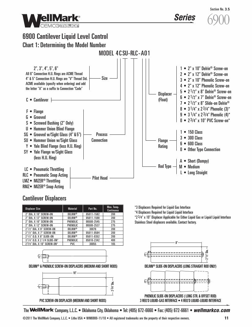
The Company, L.L.C. • Oklahoma City, Oklahoma • Tel: (405) 672-6660 • Fax: (405) 672-6661 • wellmarkco.com
Series
©2011 The WellMark Company, L.L.C. • Litho USA • WM6900-11/10 • All registered trademarks are the property of their respective owners. 11
6900Section No. 3.5
6900 Cantilever Liquid Level Control
DELRIN® & PHENOLIC SCREW-ON DISPLACERS (MEDIUM AND SHORT RODS)
PVC SCREW-ON DISPLACER (MEDIUM AND SHORT RODS)
DELRIN® SLIDE-ON DISPLACERS (LONG STRAIGHT ROD ONLY)
PHENOLIC SLIDE-ON DISPLACERS ( LONG STR. & OFFSET ROD)3 REQ'D LIQUID-GAS INTERFACE • 4 REQ'D LIQUID-LIQUID INTERFACE
2 1 /2"
Dia.
8"
2 3 /4"
Dia.
10"
1 • 2" x 10" Delrin® Screw-on 2 • 2" x 12" Delrin® Screw-on 3 • 2" x 10" Phenolic Screw-on 4 • 2" x 12" Phenolic Screw-on5 • 2 1/2" x 8" Delrin® Screw-on6 • 2 1/2" x 7" Delrin® Screw-on7 • 2 1/2" x 8" Slide-on Delrin®
8 • 3 1/4" x 2 3/4" Phenolic (3)*9 • 3 1/4" x 2 3/4" Phenolic (4)*0 • 2 3/4" x 10" PVC Screw-on*
1 • 150 Class3 • 300 Class6 • 600 Class0 • Other Type Connection
A • Short (Dumpy) M • MediumL • Long Straight
2", 3", 4", 5", 6"All 6" Connection H.U. Rings are ACME Thread4" & 5" Connection H.U. Rings are "V" Thread Std.ACME available (specify when ordering) and add the letter "A" as a suffix to Connection “Code”
C • Cantilever
F • FlangeG • Grooved S • Screwed Bushing (2" Only)U • Hammer Union Blind Flange
SG • Grooved w/Sight Glass (4" & 5")SU • Hammer Union w/Sight Glass
Y • Yale Blind Flange (less H.U. Ring)SY • Yale Flange w/Sight Glass
(less H.U. Ring)
LC • Pneumatic ThrottlingRLC • Pneumatic Snap ActingLMZ • MIZER® ThrottlingRMZ• MIZER® Snap Acting
MODEL 4 C SU-RLC -AO1
ProcessConnection
Size
Displacer(Float)
FlangeRating
Rod Type
Pilot Head
Chart 1: Determining the Model Number
*3 Displacers Required for Liquid Gas Interface*4 Displacers Required for Liquid Liquid Interface*2 3/4" x 10" Displacer Applicable for Either Liquid Gas or Liquid Liquid InterfaceStainless Steel displacers available. Contact factory.
Cantilever DisplacersDisplacer Size Material Part No. Max. Temp.
Continuous2" DIA. X 10" SCREW-ON DELRIN® 05011-1582 2002" DIA. X 12" SCREW-ON DELRIN® 05011-1590 2002" DIA. X 10" SCREW-ON PHENOLIC 06500-2545 2752" DIA. X 12" SCREW-ON PHENOLIC 06500-2537 2752 1/2" DIA. X 8" SCREW-ON DELRIN® 30076 2002 1/2" DIA. X 7" SCREW-ON DELRIN® 05011-0584 2002 1/2" O.D. X 8" SLIDE-ON DELRIN® 05011-0352 2003 1/4" O.D. X 2 1/4 SLIDE-ON* PHENOLIC 05010-2342 4002 3/4" DIA. X 10" SCREW-ON* PVC 30055 165
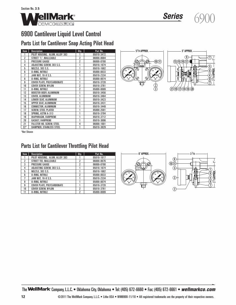
The Company, L.L.C. • Oklahoma City, Oklahoma • Tel: (405) 672-6660 • Fax: (405) 672-6661 • wellmarkco.com
Series
12 ©2011 The WellMark Company, L.L.C. • Litho USA • WM6900-11/10 • All registered trademarks are the property of their respective owners.
6900Section No. 3.5
300
255
201015
WELLMARK
psi300
255
201015
WELLMARK
psi
9
10 11
5
3
2
16
487
6" APPROX. 3 7/8
1"2 7 /
8APP
ROX.
Parts List for Cantilever Throttling Pilot HeadItem Description Qty. Part No.
1 PILOT HOUSING, ALUM. ALLOY 383 1 05010-16172 STREET TEE, MALLEABLE 2 06000-06763 PRESSURE GAUGE 2 06000-07004 ADJUSTING SCREW, 303 S.S. 1 05010-16745 NOZZLE, 303 S.S. 1 05010-16826 O-RING, NITRILE 2 05000-00337 JAM NUT, 18-8 S.S. 1 05010-23348 O-RING, NITRILE 1 05000-00749 COVER PLATE, POLYCARBONATE 1 05010-3720
10 COVER SCREW, NYLON 2 05010-376111 O-RING, NITRILE 2 05000-0009
9
10 11
5
32
1
6
487
13 15 16 12
21 19 201817 14
300
255
201015
WELLMARK
psi300
255
201015
WELLMARK
psi
1"2 7 /
8 APP
ROX.
5 3/4 APPROX. 5" APPROX.
Parts List for Cantilever Snap Acting Pilot Head Item Description Qty. Part No.
1 PILOT HOUSING, ALUM. ALLOY 383 1 05010-34722 STREET "L", MALLEABLE 2 06000-06843 PRESSURE GAUGE 2 06000-07004 ADJUSTING SCREW, 303 S.S. 1 05010-16745 NOZZLE, 303 S.S. 1 05010-16826 O-RING, NITRILE 2 05000-00337 JAM NUT, 18-8 S.S. 1 05010-23348 O-RING, NITRILE 1 05000-00749 COVER PLATE, POLYCARBONATE 1 05010-3720
10 COVER SCREW, NYLON 2 05010-376111 O-RING, NITRILE 2 05000-000912 BOOSTER BODY, ALUMINUM 1 05010-345613 COVER, ALUMINUM 1 05010-346414 LOWER SEAT, ALUMINUM 1 05010-342315 UPPER SEAT, ALUMINUM 1 05010-343116 CONNECTOR, ALUMINUM 1 05010-344917 SCREW, STEEL PLATED 1 05000-259118 SPRING, ASTM A-313 1 05010-370419 DIAPHRAGM, FAIRPRENE 1 05010-371220 GASKET, FAIRPRENE 1 05010-369621 FILLSTER HD. SCREW, STEEL 4 06000-160122* DAMPNER, STAINLESS STEEL 1 05010-3829
*Not Shown
6900 Cantilever Liquid Level Control
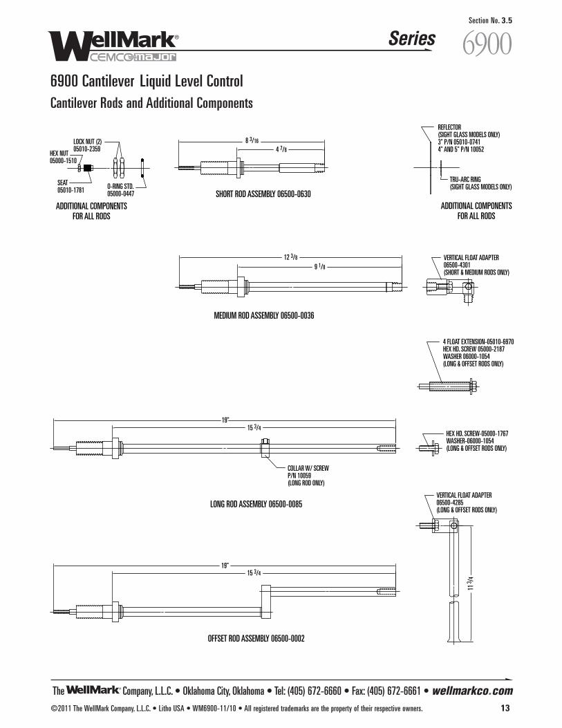
The Company, L.L.C. • Oklahoma City, Oklahoma • Tel: (405) 672-6660 • Fax: (405) 672-6661 • wellmarkco.com
Series
©2011 The WellMark Company, L.L.C. • Litho USA • WM6900-11/10 • All registered trademarks are the property of their respective owners. 13
6900Section No. 3.5
6900 Cantilever Liquid Level Control Cantilever Rods and Additional Components
4 FLOAT EXTENSION-05010-6970HEX HD. SCREW 05000-2187WASHER 06000-1054(LONG & OFFSET RODS ONLY)
MEDIUM ROD ASSEMBLY 06500-0036
VERTICAL FLOAT ADAPTER06500-4301(SHORT & MEDIUM RODS ONLY)
12 3/8
9 1/8
LONG ROD ASSEMBLY 06500-0085
HEX HD. SCREW-05000-1767WASHER-06000-1054(LONG & OFFSET RODS ONLY)
COLLAR W/ SCREWP/N 10059(LONG ROD ONLY)
19"15 3/4
SHORT ROD ASSEMBLY 06500-0630
HEX NUT05000-1510
SEAT05010-1781
LOCK NUT (2)05010-2359
O-RING STD.05000-0447
TRU-ARC RING(SIGHT GLASS MODELS ONLY)
REFLECTOR(SIGHT GLASS MODELS ONLY)3" P/N 05010-07414" AND 5" P/N 10052
ADDITIONAL COMPONENTSFOR ALL RODS
ADDITIONAL COMPONENTSFOR ALL RODS
8 3/16
4 7/8
OFFSET ROD ASSEMBLY 06500-0002
VERTICAL FLOAT ADAPTER06500-4285(LONG & OFFSET RODS ONLY)
19"15 3/4
11 3 /
4
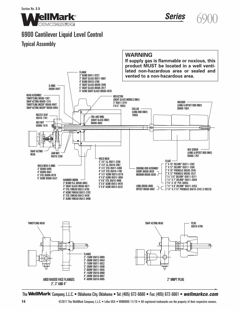
The Company, L.L.C. • Oklahoma City, Oklahoma • Tel: (405) 672-6660 • Fax: (405) 672-6661 • wellmarkco.com
Series
14 ©2011 The WellMark Company, L.L.C. • Litho USA • WM6900-11/10 • All registered trademarks are the property of their respective owners.
6900Section No. 3.5
Typical Assembly
6900 Cantilever Liquid Level Control
HEAD ASSEMBLYTHROTTLING 06500-1307SNAP ACTING 06500-1315THROTTLING MIZER® 06500-6947SNAP ACTING MIZER® 06500-6955
JAM NUT05010-2359
HAMMER UNION3" BLIND FLG. 06500-06633" SIGHT GLASS 06500-06714" STD. THREAD 05012-67054" ACME THREAD 05012-37025" STD. THREAD 05012-94395" ACME THREAD 05012-9496
WELD NECK O-RING3" 05000-04054" 05000-05615" STD. 05000-05795" ACME 05000-5537
WELD NECK3" X 5" LG. 05011-22003" X 8" LG. 05010-29614" X 5" STD. 05011-54684" X 8" STD. 05010-17994" X 5" ACME 05013-02164" X 8" ACME 05012-36945" X 8" STD. 05010-46865" X 6" ACME 05012-94705" X 8" ACME 05013-0232
SENSING ROD ASSEMBLYSHORT 06500-0630MEDIUM 06500-0036
FLOAT2" X 10" DELRIN® 05011-15822" X 12" DELRIN® 05011-15902" X 10" PHENOLIC 06500-25452" X 12" PHENOLIC 06500-25372 1/2" X 8" DELRIN® 05011-03112 1/2" X 7" DELRIN® 05011-05842 3/4" X 10" PVC 300552 1/2" X 8" DELRIN® 05011-03523 1/4" X 2 3/4" PHENOLIC 05010-2342 (3 REQ'D)
WASHER(LONG & OFFSET ROD ONLY)06000-1054
HEX SCREW(LONG & OFFSET ROD ONLY)05000-1767
FLANGE3" BLIND 05011-03373" SIGHT GLASS 05011-06674" BLIND 05010-57664" SIGHT GLASS 06500-20405" SIGHT GLASS 06500-29175" ACME SIGHT GLASS 06500-5076
REFLECTOR(SIGHT GLASS MODELS ONLY)3" 05011-07414"& 5" 10052
TRU-ARC RING(SIGHT GLASS ONLY)06000-0692
ANSI RAISED FACE FLANGES2", 3" AND 4"
2" MNPT PLUG
FLANGE2"-150RF 05013-08692"-300RF 05012-94543"-150RF 05011-59223"-300RF 05011-59483"-600RF 05011-59554"-150RF 05010-68894"-300RF 05010-68974"-600RF 05010-6905
COLLAR(LONG ROD ONLY)10059
SNAP ACTINGHEAD
THROTTLING HEAD SNAP ACTING HEAD PLUG05010-5709
O-RING05000-0447
NOZZLE SEAT05010-1781
HEX NUT05000-1510
LONG 06500-0085OFFSET 06500-0002
WARNINGIf supply gas is flammable or noxious, thisproduct MUST be located in a well venti-lated non-hazardous area or sealed andvented to a non-hazardous area.

The Company, L.L.C. • Oklahoma City, Oklahoma • Tel: (405) 672-6660 • Fax: (405) 672-6661 • wellmarkco.com
Series
©2011 The WellMark Company, L.L.C. • Litho USA • WMPT988-10/10 • All registered trademarks are the property of their respective owners. 15
PT988Section No. 3.6
PT988 Pneumatic Liquid Level SwitchApplicationWellMark’s PT988 Pneumatic Level Switch is designed for horizon-tal mounting in a tank or vessel through threaded or flanged pipeconnections (will work in an API 2" full coupling) and is excellentfor applications where space is a factor. It can be externally cagedfor vessel isolation and can be used as a high or low level alarm,as well as a liquid level control. In addition, it can be switched fromdirect to indirect action simply by inverting the unit 180˚.The PT988 features a 3-way snap-acting pilot (0 to full outputusing 20-30 psi supply pressure) or order it with an optional throt-tling pilot (3 to 15 psi output with a 20 psi supply pressure).
Features• Snap or Throttle• Small, Compact• Direct or Indirect Action• Economical
SpecificationsMax. Working Pressure . . . . . . . . . . . . . . . . . . . . . . . . 1500 psi Supply Pressure . . . . . . . . . . . . . . . 20 psi Min. – 100 psi Max.Operating Temperature . . . . . . . . . . . . . . . . . . . . -20˚F to 275˚FProcess Connections . . . . . . . . . . . . . . . . . . . 2" MNPT StandardPilot Connections . . . . . . . . . . . . . . . . . . . . . . . . . . . 1/4" FNPTPilot Mode . . . . . . . . . . . . . . . . . . . . . . . . . . . . . . . Snap Acting
ThrottlingMaterialsBody . . . . . . . . . . . . . . . . . . Plated Steel Std. (S.S. available)Float . . . . . . . . . . . . . . . . . . . . . . . . . . . . . . . Stainless Steel
(Collapse pressure: 2500 psi)Wetted Parts . . . . . . . . . . . . . . . . . . . . . . . . . Stainless SteelPilot . . . . . . . . . . . . . . . . . . . . . . . . . . . . . . . Stainless Steel
OperationAs liquid within the vessel varies, linear movement of the float isconverted to rotary movement of the actuator assembly. In the snapacting mode, as the actuator pad moves closer to the nozzle, supplypressure is diverted to signal pressure, tripping the shuttle pilot toeither full output pressure, energizing end-device, or to zero outputpressure, de-energizing end-device. In the throttling mode, as theactuator pad moves closer to the nozzle, supply pressure is diverted tooutput pressure, resulting in modulating pressure to the end-device.Direct ActingA rise in fluid level resulting in an increase of pilot output. This isaccomplished when the pilot is in the downward positionIndirect ActingA rise in fluid level resulting in a decrease of pilot output. This isaccomplished when the pilot is in the upward position.
Dimensional Data
4 9/16
6 15/16
9 1/4
2 1 /4
5 7 /8
2 1 /4
5 7 /8
6 1/2
PTP988 Level Switch
PTP988 Level Switch With External Cage
Will Work In AnAPI 2" Full Coupling
5 9/16
Optional Body
2" NPT2" NPT
4"
WELLMARK
psi
1520
25
30
10
5
0
psi
1520
25
30
10
5
0
psi
1520
25
30
10
5
0
WELLMARK
psi
1520
25
30
10
5
0
WELLMARK
psi
1520
25
30
10
5
0
WELLMARK
psi
1520
25
30
10
50
1"NPT (Typ.)
5 3 /8
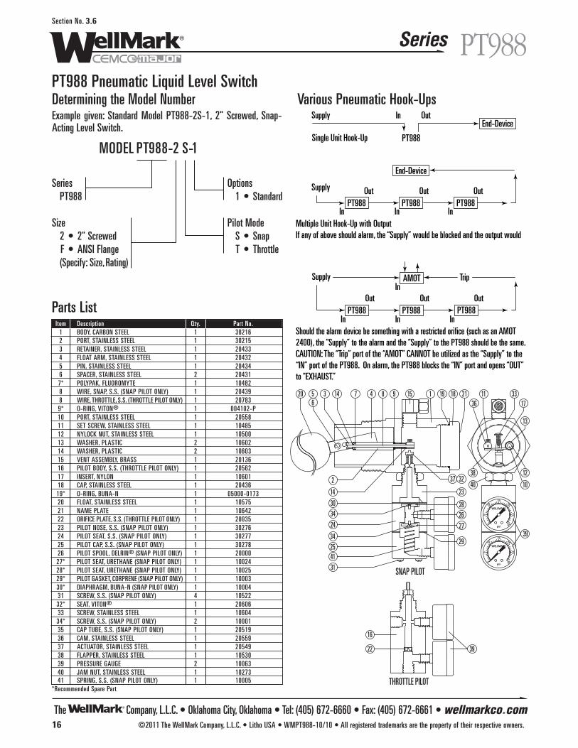
The Company, L.L.C. • Oklahoma City, Oklahoma • Tel: (405) 672-6660 • Fax: (405) 672-6661 • wellmarkco.com
Series
16 ©2011 The WellMark Company, L.L.C. • Litho USA • WMPT988-10/10 • All registered trademarks are the property of their respective owners.
PT988Section No. 3.6
PT988 Pneumatic Liquid Level Switch
1
2
3 456
7 8 9
10
1136
12
13
14
1517
18 211920
23
24
25
26
27
28
29
30
31
37 32
33
34
34
39
38
41
14
39
16
22
THROTTLE PILOT
SNAP PILOT
40
WELLMARK
psi
1520
25
30
10
5
0
WELLMARK
psi
1520
25
30
10
5
0
Parts ListItem Description Qty. Part No.
1 BODY, CARBON STEEL 1 302162 PORT, STAINLESS STEEL 1 302153 RETAINER, STAINLESS STEEL 1 204334 FLOAT ARM, STAINLESS STEEL 1 204325 PIN, STAINLESS STEEL 1 204346 SPACER, STAINLESS STEEL 2 204317* POLYPAK, FLUOROMYTE 1 104828 WIRE, SNAP, S.S. (SNAP PILOT ONLY) 1 204398 WIRE, THROTTLE, S.S. (THROTTLE PILOT ONLY) 1 207839* O-RING, VITON® 1 004102-P10 PORT, STAINLESS STEEL 1 2055811 SET SCREW, STAINLESS STEEL 1 1048512 NYLOCK NUT, STAINLESS STEEL 1 1050013 WASHER, PLASTIC 2 1060214 WASHER, PLASTIC 2 1060315 VENT ASSEMBLY, BRASS 1 2013616 PILOT BODY, S.S. (THROTTLE PILOT ONLY) 1 2056217 INSERT, NYLON 1 1060118 CAP, STAINLESS STEEL 1 2043619* O-RING, BUNA-N 1 05000-017320 FLOAT, STAINLESS STEEL 1 1057521 NAME PLATE 1 1064222 ORIFICE PLATE, S.S. (THROTTLE PILOT ONLY) 1 2003523 PILOT NOSE, S.S. (SNAP PILOT ONLY) 1 3027624 PILOT SEAT, S.S. (SNAP PILOT ONLY) 1 3027725 PILOT CAP, S.S. (SNAP PILOT ONLY) 1 3027826 PILOT SPOOL, DELRIN® (SNAP PILOT ONLY) 1 2000027* PILOT SEAT, URETHANE (SNAP PILOT ONLY) 1 1002428* PILOT SEAT, URETHANE (SNAP PILOT ONLY) 1 1002529* PILOT GASKET, CORPRENE (SNAP PILOT ONLY) 1 1000330* DIAPHRAGM, BUNA-N (SNAP PILOT ONLY) 1 1000431 SCREW, S.S. (SNAP PILOT ONLY) 4 1052232* SEAT, VITON® 1 2060633 SCREW, STAINLESS STEEL 1 1060434* SCREW, S.S. (SNAP PILOT ONLY) 2 1000135 CAP TUBE, S.S. (SNAP PILOT ONLY) 1 2051936 CAM, STAINLESS STEEL 1 2055937 ACTUATOR, STAINLESS STEEL 1 2054938 FLAPPER, STAINLESS STEEL 1 1053039 PRESSURE GAUGE 2 1006340 JAM NUT, STAINLESS STEEL 1 1027341 SPRING, S.S. (SNAP PILOT ONLY) 1 10005
*Recommended Spare Part
Determining the Model NumberExample given: Standard Model PT988-2S-1, 2" Screwed, Snap-Acting Level Switch.
Various Pneumatic Hook-Ups
Options1 • Standard
Pilot ModeS • SnapT • Throttle
SeriesPT988
Size2 • 2" ScrewedF • ANSI Flange(Specify: Size,Rating)
MODEL PT988-2 S-1PT988Single Unit Hook-Up
Supply In OutEnd-Device
PT988PT988PT988
Supply Out
In
Out
In
Out
In
End-Device
PT988PT988
AMOTSupply Trip
PT988Out
In
Out
In
InOut
InShould the alarm device be something with a restricted orifice (such as an AMOT 2400), the “Supply” to the alarm and the “Supply” to the PT988 should be the same.CAUTION: The “Trip” port of the “AMOT” CANNOT be utilized as the “Supply” to the “IN” port of the PT988. On alarm, the PT988 blocks the “IN” port and opens “OUT” to “EXHAUST.”
Multiple Unit Hook-Up with OutputIf any of above should alarm, the “Supply” would be blocked and the output would
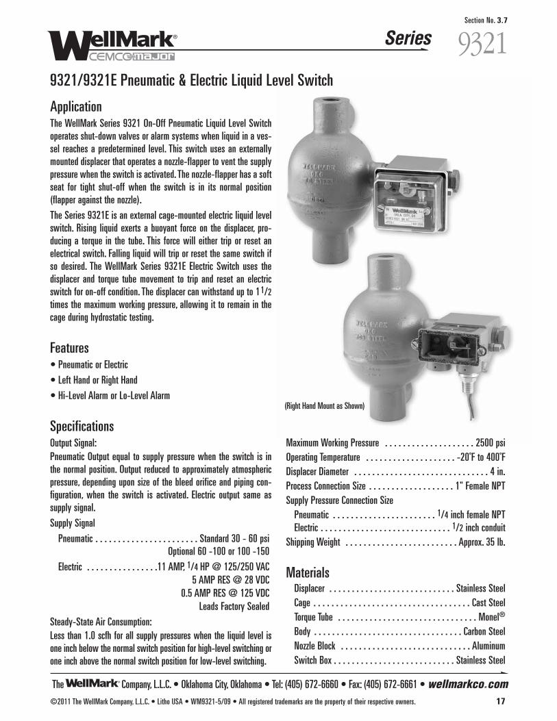
The Company, L.L.C. • Oklahoma City, Oklahoma • Tel: (405) 672-6660 • Fax: (405) 672-6661 • wellmarkco.com
Series
©2011 The WellMark Company, L.L.C. • Litho USA • WM9321-5/09 • All registered trademarks are the property of their respective owners. 17
9321Section No. 3.7
9321/9321E Pneumatic & Electric Liquid Level Switch
ApplicationThe WellMark Series 9321 On-Off Pneumatic Liquid Level Switchoperates shut-down valves or alarm systems when liquid in a ves-sel reaches a predetermined level. This switch uses an externallymounted displacer that operates a nozzle-flapper to vent the supplypressure when the switch is activated. The nozzle-flapper has a softseat for tight shut-off when the switch is in its normal position(flapper against the nozzle).
The Series 9321E is an external cage-mounted electric liquid levelswitch. Rising liquid exerts a buoyant force on the displacer, pro-ducing a torque in the tube. This force will either trip or reset anelectrical switch. Falling liquid will trip or reset the same switch ifso desired. The WellMark Series 9321E Electric Switch uses thedisplacer and torque tube movement to trip and reset an electricswitch for on-off condition. The displacer can withstand up to 11/2times the maximum working pressure, allowing it to remain in thecage during hydrostatic testing.
Features• Pneumatic or Electric
• Left Hand or Right Hand
• Hi-Level Alarm or Lo-Level Alarm
SpecificationsOutput Signal:Pneumatic Output equal to supply pressure when the switch is inthe normal position. Output reduced to approximately atmosphericpressure, depending upon size of the bleed orifice and piping con-figuration, when the switch is activated. Electric output same assupply signal.
Supply Signal
Pneumatic . . . . . . . . . . . . . . . . . . . . . . . Standard 30 - 60 psiOptional 60 -100 or 100 -150
Electric . . . . . . . . . . . . . . . .11 AMP, 1/4 HP @ 125/250 VAC5 AMP RES @ 28 VDC
0.5 AMP RES @ 125 VDCLeads Factory Sealed
Steady-State Air Consumption: Less than 1.0 scfh for all supply pressures when the liquid level isone inch below the normal switch position for high-level switching orone inch above the normal switch position for low-level switching.
Maximum Working Pressure . . . . . . . . . . . . . . . . . . . . 2500 psiOperating Temperature . . . . . . . . . . . . . . . . . . . . -20˚F to 400˚FDisplacer Diameter . . . . . . . . . . . . . . . . . . . . . . . . . . . . . . 4 in.Process Connection Size . . . . . . . . . . . . . . . . . . . 1" Female NPTSupply Pressure Connection Size
Pneumatic . . . . . . . . . . . . . . . . . . . . . . . 1/4 inch female NPTElectric . . . . . . . . . . . . . . . . . . . . . . . . . . . . . 1/2 inch conduit
Shipping Weight . . . . . . . . . . . . . . . . . . . . . . . . . Approx. 35 lb.
MaterialsDisplacer . . . . . . . . . . . . . . . . . . . . . . . . . . . . Stainless SteelCage . . . . . . . . . . . . . . . . . . . . . . . . . . . . . . . . . . . Cast SteelTorque Tube . . . . . . . . . . . . . . . . . . . . . . . . . . . . . . . Monel®
Body . . . . . . . . . . . . . . . . . . . . . . . . . . . . . . . . . Carbon SteelNozzle Block . . . . . . . . . . . . . . . . . . . . . . . . . . . . . AluminumSwitch Box . . . . . . . . . . . . . . . . . . . . . . . . . . . Stainless Steel
(Right Hand Mount as Shown)
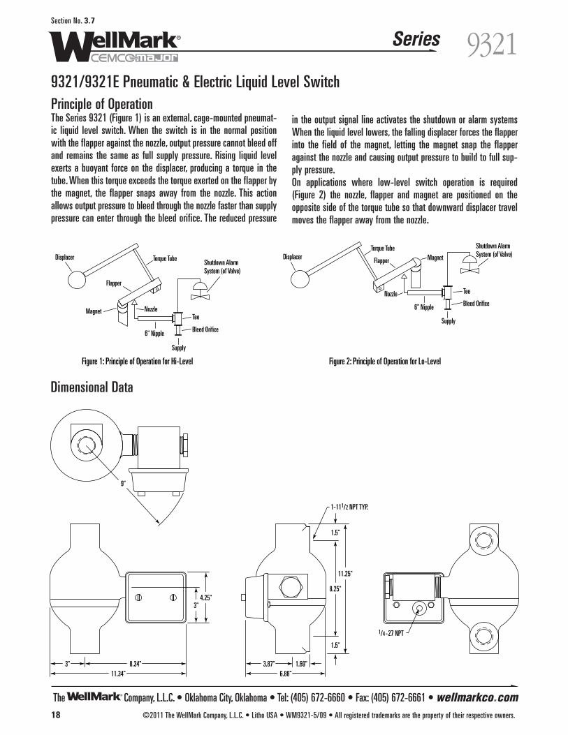
The Company, L.L.C. • Oklahoma City, Oklahoma • Tel: (405) 672-6660 • Fax: (405) 672-6661 • wellmarkco.com
Series
9"
3"11.34"
8.34" 3.87"6.88"
1.69"
1/4-27 NPT
3"4.25"
8.25"
1.5"
1-111/2 NPT TYP.
1.5"
11.25"
18 ©2011 The WellMark Company, L.L.C. • Litho USA • WM9321-5/09 • All registered trademarks are the property of their respective owners.
9321Section No. 3.7
9321/9321E Pneumatic & Electric Liquid Level SwitchPrinciple of OperationThe Series 9321 (Figure 1) is an external, cage-mounted pneumat-ic liquid level switch. When the switch is in the normal positionwith the flapper against the nozzle, output pressure cannot bleed offand remains the same as full supply pressure. Rising liquid levelexerts a buoyant force on the displacer, producing a torque in thetube. When this torque exceeds the torque exerted on the flapper bythe magnet, the flapper snaps away from the nozzle. This actionallows output pressure to bleed through the nozzle faster than supplypressure can enter through the bleed orifice. The reduced pressure
in the output signal line activates the shutdown or alarm systemsWhen the liquid level lowers, the falling displacer forces the flapperinto the field of the magnet, letting the magnet snap the flapperagainst the nozzle and causing output pressure to build to full sup-ply pressure.On applications where low-level switch operation is required(Figure 2) the nozzle, flapper and magnet are positioned on theopposite side of the torque tube so that downward displacer travelmoves the flapper away from the nozzle.
Dimensional Data
Displacer
Magnet Nozzle
Torque Tube Shutdown AlarmSystem (of Valve)
Tee
Bleed Orifice
Figure 1: Principle of Operation for Hi-Level Figure 2: Principle of Operation for Lo-Level
Supply
Flapper
6" Nipple
6" Nipple
Displacer Magnet
Nozzle
Torque Tube Shutdown AlarmSystem (of Valve)
Tee
Bleed Orifice
Supply
Flapper
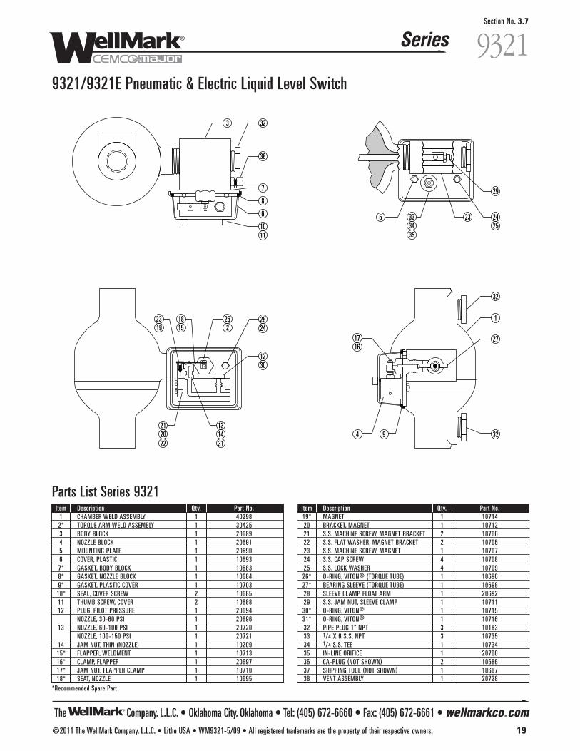
The Company, L.L.C. • Oklahoma City, Oklahoma • Tel: (405) 672-6660 • Fax: (405) 672-6661 • wellmarkco.com
Series
©2011 The WellMark Company, L.L.C. • Litho USA • WM9321-5/09 • All registered trademarks are the property of their respective owners. 19
9321Section No. 3.7
9321/9321E Pneumatic & Electric Liquid Level Switch
1230
2524
262
1815
2319
212022
1431
13
1716
4 9 32
27
1
32
23 2425
29
5 333435
3 32
7
38
8
6
1011
Parts List Series 9321Item Description Qty. Part No.
1 CHAMBER WELD ASSEMBLY 1 402982* TORQUE ARM WELD ASSEMBLY 1 304253 BODY BLOCK 1 206894 NOZZLE BLOCK 1 206915 MOUNTING PLATE 1 206906 COVER, PLASTIC 1 106937* GASKET, BODY BLOCK 1 106838* GASKET, NOZZLE BLOCK 1 106849* GASKET, PLASTIC COVER 1 10703
10* SEAL, COVER SCREW 2 1068511 THUMB SCREW, COVER 2 1068812 PLUG, PILOT PRESSURE 1 20694
NOZZLE, 30-60 PSI 1 2069613 NOZZLE, 60-100 PSI 1 20720
NOZZLE, 100-150 PSI 1 2072114 JAM NUT, THIN (NOZZLE) 1 1020915* FLAPPER, WELDMENT 1 1071316* CLAMP, FLAPPER 1 2069717* JAM NUT, FLAPPER CLAMP 1 1071018* SEAT, NOZZLE 1 10695
*Recommended Spare Part
Item Description Qty. Part No.19* MAGNET 1 1071420 BRACKET, MAGNET 1 1071221 S.S. MACHINE SCREW, MAGNET BRACKET 2 1070622 S.S. FLAT WASHER, MAGNET BRACKET 2 1070523 S.S. MACHINE SCREW, MAGNET 1 1070724 S.S. CAP SCREW 4 1070825 S.S. LOCK WASHER 4 1070926* O-RING, VITON® (TORQUE TUBE) 1 1069627* BEARING SLEEVE (TORQUE TUBE) 1 1069828 SLEEVE CLAMP, FLOAT ARM 1 2069229 S.S. JAM NUT, SLEEVE CLAMP 1 1071130* O-RING, VITON® 1 1071531* O-RING, VITON® 1 1071632 PIPE PLUG 1" NPT 3 1018333 1/4 X 6 S.S. NPT 3 1073534 1/4 S.S. TEE 1 1073435 IN-LINE ORIFICE 1 2070036 CA-PLUG (NOT SHOWN) 2 1068637 SHIPPING TUBE (NOT SHOWN) 1 1068738 VENT ASSEMBLY 1 20728

The Company, L.L.C. • Oklahoma City, Oklahoma • Tel: (405) 672-6660 • Fax: (405) 672-6661 • wellmarkco.com
Series
20 ©2011 The WellMark Company, L.L.C. • Litho USA • WM9321-5/09 • All registered trademarks are the property of their respective owners.
9321Section No. 3.7
3
41
1 46 471748 49
42 43 44 45
25 24 2 16 39 11 40
27 28 29 32
26
7
Parts List Series 9321EItem Description Qty. Part No.
1 CHAMBER WELD ASSLY 1 402982* TORQUE TUBE WELD ASSLY 1 304253 BODY BLOCK 1 206897* GASKET 1 1068311 THUMB SCREW 2 1068816* CLAMP 1 2069717* JAM NUT 1 1071024 S.S. CAP SCREW 2 1070825 S.S. LOCK WASHER 2 1070926* O-RING, VITON® 1 1069627* BEARING SLEEVE 1 1069828 SLEEVE CLAMP 1 2069229 S.S. JAM NUT 1 1071132 PIPE PLUG 3 10183
*Recommended Spare Part
Item Description Qty. Part No.36 CA-PLUG (NOT SHOWN) 2 1068637 SHIPPING TUBE (NOT SHOWN) 1 1068739 COVER & GASKET 1 1076440* O-RING 2 1090541 SWITCH ARM 1 1076542 DRIVE SCREW 2 1007543 S. S. JAM NUT 1 1090144 NAMEPLATE 1 1077245 S.S. CAP SCREW 1 1090046 CA-PLUG 1 10906
47* SPDT SWITCH 1 10783DPDT SWITCH (OPTIONAL) 10790
48 S.S. SET SCREW 2 1079449 SWITCH BOX 1 30455
9321/9321E Pneumatic & Electric Liquid Level Switch
How to OrderPneumatic
Left Hand Hi 9321 LHLeft Hand Lo 9321 LLRight Hand Hi 9321 RHRight Hand Lo 9321 RL
ElectricAdd the Letter “E”after 9321Example: 9321E-LH
Repair KitsMinor Repair Kit 20736Consists of: Part No.GASKET 10683GASKET 10684GASKET 10685FLAPPER SEAT 10695O-RING 10696BEARING SLEEVE 10698GASKET 10703FLAPPER ASSEMBLY 10713HOLDING MAGNET 10714O-RING 10715O-RING 10716Major Repair Kit 20737Consists of: Part No.SAME AS 20735 (ABOVE) PLUS TORQUE TUBE ASSY. 30425
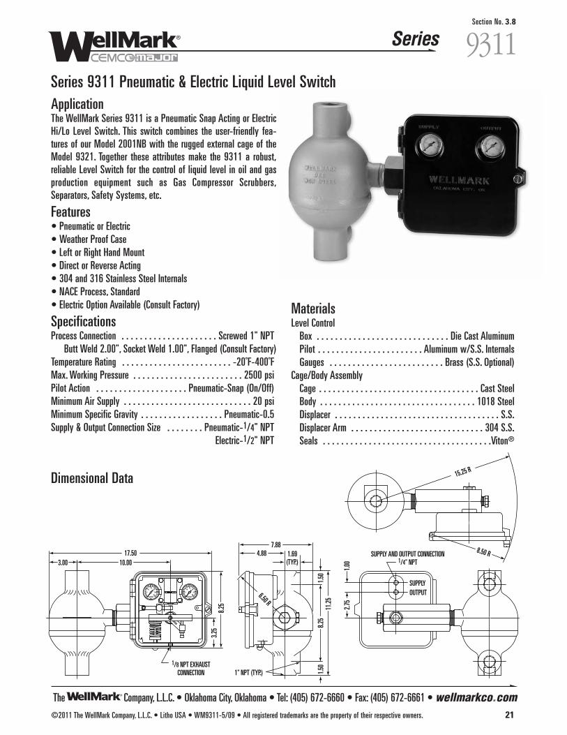
The Company, L.L.C. • Oklahoma City, Oklahoma • Tel: (405) 672-6660 • Fax: (405) 672-6661 • wellmarkco.com
Series
©2011 The WellMark Company, L.L.C. • Litho USA • WM9311-5/09 • All registered trademarks are the property of their respective owners. 21
Section No. 3.8
9311Series 9311 Pneumatic & Electric Liquid Level SwitchApplicationThe WellMark Series 9311 is a Pneumatic Snap Acting or ElectricHi/Lo Level Switch. This switch combines the user-friendly fea-tures of our Model 2001NB with the rugged external cage of theModel 9321. Together these attributes make the 9311 a robust,reliable Level Switch for the control of liquid level in oil and gasproduction equipment such as Gas Compressor Scrubbers,Separators, Safety Systems, etc.
Features• Pneumatic or Electric• Weather Proof Case • Left or Right Hand Mount• Direct or Reverse Acting• 304 and 316 Stainless Steel Internals• NACE Process, Standard• Electric Option Available (Consult Factory)
SpecificationsProcess Connection . . . . . . . . . . . . . . . . . . . . . Screwed 1" NPT
Butt Weld 2.00", Socket Weld 1.00", Flanged (Consult Factory)Temperature Rating . . . . . . . . . . . . . . . . . . . . . . . . -20˚F-400˚FMax. Working Pressure . . . . . . . . . . . . . . . . . . . . . . . . 2500 psiPilot Action . . . . . . . . . . . . . . . . . . . . Pneumatic-Snap (On/Off)Minimum Air Supply . . . . . . . . . . . . . . . . . . . . . . . . . . . . 20 psiMinimum Specific Gravity . . . . . . . . . . . . . . . . . . Pneumatic-0.5Supply & Output Connection Size . . . . . . . . Pneumatic-1/4" NPT
Electric-1/2" NPT
MaterialsLevel Control
Box . . . . . . . . . . . . . . . . . . . . . . . . . . . . . Die Cast AluminumPilot . . . . . . . . . . . . . . . . . . . . . . . Aluminum w/S.S. InternalsGauges . . . . . . . . . . . . . . . . . . . . . . . . . Brass (S.S. Optional)
Cage/Body AssemblyCage . . . . . . . . . . . . . . . . . . . . . . . . . . . . . . . . . . . Cast SteelBody . . . . . . . . . . . . . . . . . . . . . . . . . . . . . . . . . . 1018 SteelDisplacer . . . . . . . . . . . . . . . . . . . . . . . . . . . . . . . . . . . . S.S.Displacer Arm . . . . . . . . . . . . . . . . . . . . . . . . . . . . . 304 S.S.Seals . . . . . . . . . . . . . . . . . . . . . . . . . . . . . . . . . . . . .Viton®
SUPPLYOUTPUT
SUPPLY AND OUTPUT CONNECTION1/4" NPT
2.75
1.00
1.50
8.25
11.25
1.50
1" NPT (TYP.)
4.88
3.25
8.25
1.69(TYP.)3.00 10.00
17.507.88
6.50 R
8.50 R
15.25 R
1/8 NPT EXHAUSTCONNECTION
Dimensional Data

31
44
32
41
1211
30
28 22 21 19 29 20 28 16 13 40 1817 14
3738
23
15
3
34
39
10
7
42
6
8
43
9
5
4
2
133 23 26 27 25 36 35 24
Series 9311 Pneumatic & Electric Liquid Level Switch
The Company, L.L.C. • Oklahoma City, Oklahoma • Tel: (405) 672-6660 • Fax: (405) 672-6661 • wellmarkco.com
Series
22 ©2011 The WellMark Company, L.L.C. • Litho USA • WM9311-5/09 • All registered trademarks are the property of their respective owners.
9311Section No. 3.8
Control ActionD • DirectR • Indirect
MountingR • Right HandL • Left Hand
Series 9311
Pilot S • SnapT • Throttling
MODEL 9311- S L D
Determining the Model NumberExample given: Standard Model 9311-SLD, Snap Acting, Left HandMounting, Direct Control Level Switch.
Parts ListItem Description Qty. Part No.
1 CONTROL BOX, DIE CAST ALUMINUM 1 05012-48412 COVER, DIE CAST ALUMINUM 1 05012-4834*3 BOX SEAL, NEOPRENE 1 06000-5097
*4 SNAP PILOT ASSEMBLY 1 06500-5304THROTTLE PILOT ASSEMBLY 1 06500-5387
5 BODY, ASTM A-108GR. 1018 1 05013-14586 PIVOT SHAFT, ASTM A-276 TY.316 1 05013-1482*7 O-RING, VITON® 2 05000-0769*8 BACK UP RING, TEFLON® 2 06000-11799 SHAFT RETAINER, ASTM A-276 TY.316 2 05012-9398
*10 O-RING, VITON® 2 05000-115511 SPACER, ASTM A-276 TY. 316 1 05011-449512 CAP SCREW, 18-8 S.S. 2 05000-557813 CAP SCREW, 18-8 S.S. 1 05000-545314 ADJUSTING BAR, ALUMINUM 1 05011-443815 CAP SCREW, 18-8 S.S. 2 05000-252616 TORQUE BAR, ALUMINUM 1 05011-454517 ADJUSTING SCREW, ASTM A-276 TY.316 1 05011-453718 JAM NUT, 18-8 S.S. 1 05000-255919 STUD, 18-8 S.S. 1 05011-455220 LOWER SPRING GUIDE, ALUMINUM 1 05011-452921 SPRING, ASTM A-313 1 06000-415722 UPPER SPRING GUIDE, ALUMINUM 1 05011-447923 STUD, FLAPPER BAR, ASTM A-276 TY.316 2 05012-937124 FLAPPER BAR 1 05011-4404
*Recommended Spare Part
Item Description Qty. Part No.25 TRU-ARC RING, PH 15-7 MO 1 06000-138526 FULCRUM, ALUMINUM 1 05011-441227 THUMB SCREW, S.S./PLASTIC 1 06500-542928 NY-LOC NUT, STAINLESS STEEL 2 05000-256729 ACORN NUT, STAINLESS STEEL 1 05000-257530 CHAMBER W/FLOAT ARM 1 4029931 LOCK WASHER 1 1070932 CAP SCREW 1 1000233 HINGE PIN, STEEL PLATED 2 06000-753734 GASKET 1 06000-481935 CAP SCREW 4 05000-531336 PILOT CLAMP 1 05012-632537 PANEL SCREW, STAINLESS STEEL 1 06000-115338 PANEL SCREW RETAINER, STAINLESS STEEL 1 06000-267239 SERIAL TAG, ALUMINUM 1 06000-1922*40 THREAD SEAL, STEEL/BUNA N 1 06000-0395*41 GASKET 1 1001642 BEARING, STAINLESS STEEL 2 06000-755243 TOLERANCE RING, STAINLESS STEEL 2 06000-756044 PLUG 1 06000-114645 COVER GLASS, LEXAN (NOT SHOWN) 2 1091646 COVER GLASS PLATE, S.S. (NOT SHOWN) 2 1091547 COVER GLASS GASKET, NEOPRENE (NOT SHOWN) 2 1091748 COVER SCREW, PLATED STEEL (NOT SHOWN) 8 001501-P
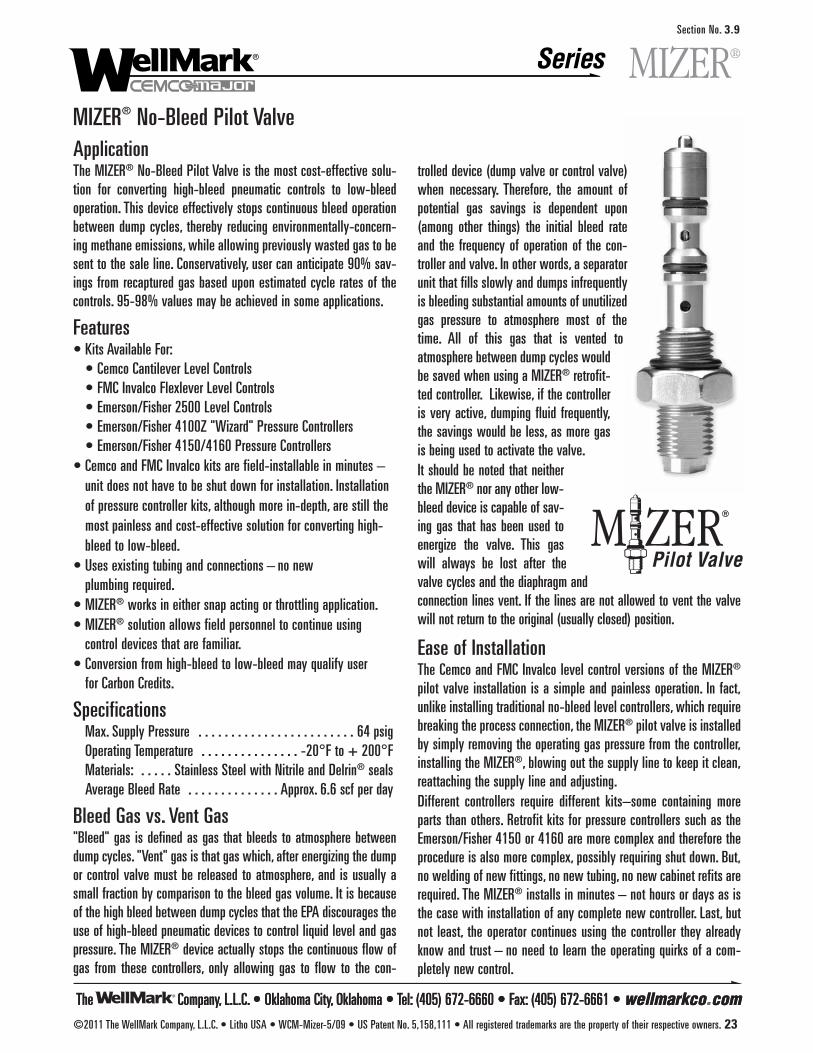
The Company, L.L.C. • Oklahoma City, Oklahoma • Tel: (405) 672-6660 • Fax: (405) 672-6661 • wellmarkco.com
SeriesSection No. 3.9
The Company, L.L.C. • Oklahoma City, Oklahoma • Tel: (405) 672-6660 • Fax: (405) 672-6661 • wellmarkco.com©2011 The WellMark Company, L.L.C. • Litho USA • WCM-Mizer-5/09 • US Patent No. 5,158,111 • All registered trademarks are the property of their respective owners. 23
MIZER® No-Bleed Pilot ValveApplicationThe MIZER® No-Bleed Pilot Valve is the most cost-effective solu-tion for converting high-bleed pneumatic controls to low-bleedoperation. This device effectively stops continuous bleed operationbetween dump cycles, thereby reducing environmentally-concern-ing methane emissions, while allowing previously wasted gas to besent to the sale line. Conservatively, user can anticipate 90% sav-ings from recaptured gas based upon estimated cycle rates of thecontrols. 95-98% values may be achieved in some applications.
Features• Kits Available For:
• Cemco Cantilever Level Controls• FMC Invalco Flexlever Level Controls• Emerson/Fisher 2500 Level Controls• Emerson/Fisher 4100Z "Wizard" Pressure Controllers• Emerson/Fisher 4150/4160 Pressure Controllers
• Cemco and FMC Invalco kits are field-installable in minutes – unit does not have to be shut down for installation. Installation of pressure controller kits, although more in-depth, are still the most painless and cost-effective solution for converting high-bleed to low-bleed.
• Uses existing tubing and connections – no new plumbing required.
• MIZER® works in either snap acting or throttling application.• MIZER® solution allows field personnel to continue using
control devices that are familiar.• Conversion from high-bleed to low-bleed may qualify user
for Carbon Credits.
SpecificationsMax. Supply Pressure . . . . . . . . . . . . . . . . . . . . . . . . 64 psigOperating Temperature . . . . . . . . . . . . . . . -20°F to + 200°FMaterials: . . . . . Stainless Steel with Nitrile and Delrin® sealsAverage Bleed Rate . . . . . . . . . . . . . . Approx. 6.6 scf per day
Bleed Gas vs. Vent Gas"Bleed" gas is defined as gas that bleeds to atmosphere betweendump cycles. "Vent" gas is that gas which, after energizing the dumpor control valve must be released to atmosphere, and is usually asmall fraction by comparison to the bleed gas volume. It is becauseof the high bleed between dump cycles that the EPA discourages theuse of high-bleed pneumatic devices to control liquid level and gaspressure. The MIZER® device actually stops the continuous flow ofgas from these controllers, only allowing gas to flow to the con-
MIZER®
trolled device (dump valve or control valve)when necessary. Therefore, the amount ofpotential gas savings is dependent upon(among other things) the initial bleed rateand the frequency of operation of the con-troller and valve. In other words, a separatorunit that fills slowly and dumps infrequentlyis bleeding substantial amounts of unutilizedgas pressure to atmosphere most of thetime. All of this gas that is vented toatmosphere between dump cycles wouldbe saved when using a MIZER® retrofit-ted controller. Likewise, if the controlleris very active, dumping fluid frequently,the savings would be less, as more gasis being used to activate the valve.It should be noted that neitherthe MIZER® nor any other low-bleed device is capable of sav-ing gas that has been used toenergize the valve. This gaswill always be lost after thevalve cycles and the diaphragm andconnection lines vent. If the lines are not allowed to vent the valvewill not return to the original (usually closed) position.
Ease of InstallationThe Cemco and FMC Invalco level control versions of the MIZER®
pilot valve installation is a simple and painless operation. In fact,unlike installing traditional no-bleed level controllers, which requirebreaking the process connection, the MIZER® pilot valve is installedby simply removing the operating gas pressure from the controller,installing the MIZER®, blowing out the supply line to keep it clean,reattaching the supply line and adjusting.Different controllers require different kits–some containing moreparts than others. Retrofit kits for pressure controllers such as theEmerson/Fisher 4150 or 4160 are more complex and therefore theprocedure is also more complex, possibly requiring shut down. But,no welding of new fittings, no new tubing, no new cabinet refits arerequired. The MIZER® installs in minutes – not hours or days as isthe case with installation of any complete new controller. Last, butnot least, the operator continues using the controller they alreadyknow and trust – no need to learn the operating quirks of a com-pletely new control.

The Company, L.L.C. • Oklahoma City, Oklahoma • Tel: (405) 672-6660 • Fax: (405) 672-6661 • wellmarkco.com
SeriesSection No. 3.9
The Company, L.L.C. • Oklahoma City, Oklahoma • Tel: (405) 672-6660 • Fax: (405) 672-6661 • wellmarkco.com24 ©2011 The WellMark Company, L.L.C. • Litho USA • WCM-Mizer-5/09 • US Patent No. 5,158,111 • All registered trademarks are the property of their respective owners.
Method of Operation
ControllerBody
PositionLock Nut
( Fig. 1)Non-Venting
Closed
( Fig. 2)Non-Venting
Actuating
( Fig. 3)Non-Continuous
Venting
Level ControllerSensing Rod Seat
POSITIONEQUILIBRIUM RELEASED
Exhaust
ActuatorOutlet Supply
Seal “A”( CLOSED )
Seal “A”( CLOSES )
Seal “B”( OPENS )
Seal “A”( OPENS )
Seal “B”( REMAINS CLOSED )
Exhaust FromActuator Operation
And ActuatorLine Only
Seal “B”( CLOSED )
Seal “C”Dynamic Seal
Operating Supply
Actuation Poppet
DEPRESSED Equilibrium Position: (Non-Venting Closed)
When the MIZER® Pilot Valve is in “SteadyState”, both Seal “A” and Seal “B” are closedand the Control Flapper is in neutral position.(See Fig. 1)
Depressed Position: (Non-Venting Actuating)When the Control Flapper depresses theActuation Poppet, Seal “A” is opened, supply-ing gas to the process valve. Seal “B” isclosed, preventing gas from bleeding or vent-ing through the vent port. The MIZER® PilotValve is designed so that the gas flow isrelated to the position of the controller flap-per. (See Fig. 2)
Released Position: (Non-Continuous Venting)When the Control Flapper is released it clos-es Seal “A” and opens Seal “B” allowing gasto vent. Venting occurs ONLY when the controlvalve calls for it, and then, ONLY the gas inthe process line and actuator is released. (See Fig. 3)
MIZER® No-Bleed Pilot Valve
MIZER®
Liquid Level Controls & Pressure Controllers • Potential Savings per Control (3 to 15 psig controllers*)Based upon typical onshore facility* supply pressure of 20 psig and $6.00 gas
Type Manufacturer Model Supply Pressure Bleed Rate Air Bleed Rate Gas Daily Bleed Rate Yearly Bleed Rate Annual Dollars LOST Control psig SCFH SCFH SCFD SCFY to Emissions
CEMCO 6900 20 19.7 26 614 224,119 $1,344.72EMERSON/FISHER 2500 20 27 35 842 307,169 $1,843.01EMERSON/FISHER 2502 20 27 35 842 307,169 $1,843.01EMERSON/FISHER 2506 20 27 35 842 307,169 $1,843.01
LIQUID FISHER 3570 20 13 17 405 147,896 $887.38LEVEL FISHER 3582 20 13 17 405 147,896 $887.38
FISHER 3660 20 5.2 7 162 59,158 $354.95FMC INVALCO 415 20 23 30 717 261,662 $1,569.97FMC INVALCO 215 20 23 30 717 261,662 $1,569.97FMC INVALCO 402 20 23 30 717 261,662 $1,569.97
EMERSON/FISHER 4100Z 20 33 43 1029 375,429 $2,252.57 PRESSURE EMERSON/FISHER 4150 20 27 35 842 307,169 $1,843.01
EMERSON/FISHER 4160 20 27 35 842 307,169 $1,843.01
* Offshore facilities commonly use 6 to 30 psig controllers with average supply pressure of 35 psig. Bleed rates and dollars lost due to emissions would conservatively be 1.5 times those listed above.
Conversion Kit Assembly Part NumbersType Conversion Kit Part
ConvertsControl Model Number Number1110-111 06500-6905 CEMCO CANTILEVER CONTROL
LIQUID LEVEL 4010-111 31066 FMC INVALCO FLEXLEVER CONTROL7010-111 06500-7018 EMERSON/FISHER 2500 CONTROL
PRESSURE5010-111 06500-7093 EMERSON/FISHER 4100Z
"WIZARD" CONTROLLER
8010-111 06500-7019 EMERSON/FISHER 4150/4160 CONTROLLER
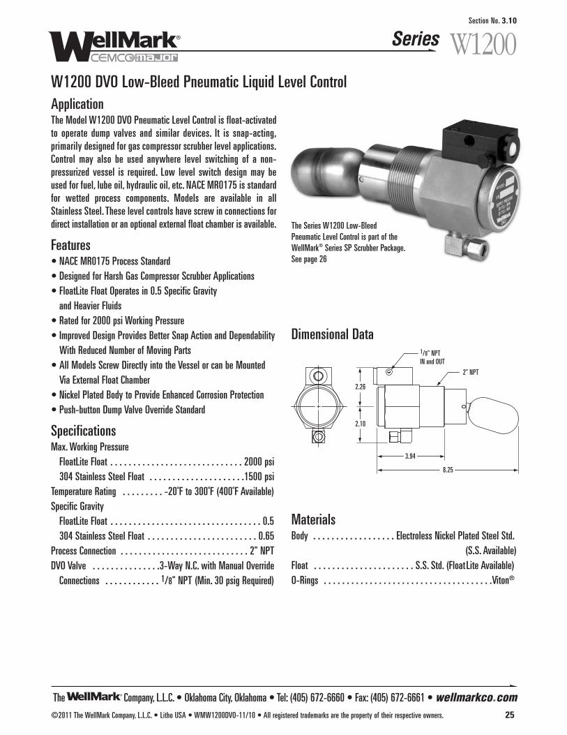
The Company, L.L.C. • Oklahoma City, Oklahoma • Tel: (405) 672-6660 • Fax: (405) 672-6661 • wellmarkco.com
Series
©2011 The WellMark Company, L.L.C. • Litho USA • WMW1200DVO-11/10 • All registered trademarks are the property of their respective owners. 25
W1200Section No. 3.10
W1200 DVO Low-Bleed Pneumatic Liquid Level ControlApplicationThe Model W1200 DVO Pneumatic Level Control is float-activatedto operate dump valves and similar devices. It is snap-acting,primarily designed for gas compressor scrubber level applications.Control may also be used anywhere level switching of a non-pressurized vessel is required. Low level switch design may beused for fuel, lube oil, hydraulic oil, etc. NACE MR0175 is standardfor wetted process components. Models are available in allStainless Steel. These level controls have screw in connections fordirect installation or an optional external float chamber is available.
Features• NACE MR0175 Process Standard• Designed for Harsh Gas Compressor Scrubber Applications• FloatLite Float Operates in 0.5 Specific Gravity
and Heavier Fluids• Rated for 2000 psi Working Pressure• Improved Design Provides Better Snap Action and Dependability
With Reduced Number of Moving Parts• All Models Screw Directly into the Vessel or can be Mounted
Via External Float Chamber• Nickel Plated Body to Provide Enhanced Corrosion Protection• Push-button Dump Valve Override Standard
SpecificationsMax. Working Pressure
FloatLite Float . . . . . . . . . . . . . . . . . . . . . . . . . . . . . 2000 psi304 Stainless Steel Float . . . . . . . . . . . . . . . . . . . . .1500 psi
Temperature Rating . . . . . . . . . -20˚F to 300˚F (400˚F Available)Specific Gravity
FloatLite Float . . . . . . . . . . . . . . . . . . . . . . . . . . . . . . . . . 0.5 304 Stainless Steel Float . . . . . . . . . . . . . . . . . . . . . . . . 0.65
Process Connection . . . . . . . . . . . . . . . . . . . . . . . . . . . . 2" NPTDVO Valve . . . . . . . . . . . . . . .3-Way N.C. with Manual Override
Connections . . . . . . . . . . . . 1/8" NPT (Min. 30 psig Required)
Dimensional Data 1/8" NPTIN and OUT
2.26
2.10
8.25
3.94
2" NPT
The Series W1200 Low-Bleed Pneumatic Level Control is part of theWellMark® Series SP Scrubber Package. See page 26
MaterialsBody . . . . . . . . . . . . . . . . . . Electroless Nickel Plated Steel Std.
(S.S. Available)Float . . . . . . . . . . . . . . . . . . . . . . S.S. Std. (Float Lite Available) O-Rings . . . . . . . . . . . . . . . . . . . . . . . . . . . . . . . . . . . . .Viton®

The Company, L.L.C. • Oklahoma City, Oklahoma • Tel: (405) 672-6660 • Fax: (405) 672-6661 • wellmarkco.com
Series
26 ©2011 The WellMark Company, L.L.C. • Litho USA • WMW1200 DVO-11/10 • All registered trademarks are the property of their respective owners.
W1200Section No. 3.10
W1200 DVO Low-Bleed Pneumatic Liquid Level ControlDetermining the Model NumberExample given: Standard Model W1200 DVO-*–Series W1200 DVO Pneumatic Level Control with Manual Override.
The WellMark Series SP Scrubber Package
Series 790 Horizontal LevelControl Floatswitch See Section 2.1
Series W2600 Threaded Safety Relief ValveSee Section 4.1a
Series W67 “Mini Gun II“General Purpose Instrument and Gas Pressure RegulatorSee Section 5.6
Series W1200 DVOLow-Bleed Pneumatic Liquid Level Control
Series WDVPneumatic DiaphragmActuated Dump ValveSee Section 8.8
The system provides for liquid control in gas scrubber applicationsby dumping liquids to drain and protecting compressors with a highliquid level switch. Wetted metal parts are made to survive constantuse in corrosive environments.
Pneumatic Level ControlFloat actuated level snap acting switch controls pneumatic pressureto open and close the dump valve.
High Level Shutdown SwitchStainless Steel float actuated level switches to alarm and/or shut-down the equipment. See Section 2 for more information.
Pneumatic Dump Valves2-Piece union design with manual valve operator allows soft plugand hard seat to be replaced without disassembling outlet piping orscrubber pipe connection. Diaphragm actuated valves operate on 30to 70 psi. See Section 8 for more information.
R • Airset RegulatorSS • S.S. BodyFL • FloatLite (.5 SG)H • Hi-Temp (400˚F)
EC • External CageE** • Float Arm Extension
MODEL W1200 DVO - *
Options
Notes: *For options, add code to end of Model Number.**Add length of extension behind code (E). For example, the code for a 3" Extension would be ”E3“.
Wellmark Series SP Scrubber Package includes 790, W1200 DVOR, WDV and optional W2600 Safety Relief Valve.
LR** • Less RegulatorRV1 • With 1" Relief ValveRV2 • With 2" Relief Valve
Notes: *For options, add code to end of Model Number.**Regulator provided at no extra charge.
1 • 20-100-202 • 20-100-153 • 20-100-054 • 10-075-185 • 10-050-18
MODEL SP 1 *
WDV ValveOptions

31
3021
2223
25
2627
2829
24
1411
13
10
16
15
98
124 36
1
35
3
2
33
347
65
32
20
19
17
18
Parts ListItem Description Qty. Part No.
1 BODY, STEEL 1 311012 WIRE, STAINLESS STEEL 1 215463 SPACER 1 215474 WASHER, NYLON 1 106035 QUAD RING 1 112566 PORT, STAINLESS STEEL 1 215457 O-RING, NITRILE 1 104838 CAM, STAINLESS STEEL 1 215489 SET SCREW 1 10485
10 PORT, STAINLESS STEEL 1 2055811 WASHER, NYLON 2 1060212 ACTUATOR, STAINLESS STEEL 1 1124913 SEAT, NITRILE 1 2151314 NYLOC NUT, STAINLESS STEEL 1 05000-256715 O-RING, NITRILE 1 05000-017316 CAP, STAINLESS STEEL 1 2043617 NOZZLE, STAINLESS STEEL 1 2152118 O-RING, NITRILE 1 05000-000919 NOZZLE BODY, STAINLESS STEEL 1 21525
Item Description Qty. Part No.20 O-RING, NITRILE 1 05000-003321 PILOT HOUSING, ALUMINUM 1 2152322 DIAPHRAGM, NITRILE 1 2152723 SPOOL, ALUMINUM 1 2152424 O-RING, NITRILE 2 05000-005825 STEM, STAINLESS STEEL 1 2152226 PLUG,NITRILE 1 2152627 SPRING, STAINLESS STEEL 1 1125028 MANUAL BUTTON, DELRIN® 1 2152029 PILOT CAP, ALUMINUM 1 2151930 BREATHER, PLASTIC 1 05011-872931 SCREW, STAINLESS STEEL 2 05000-615332 COUNTER WEIGHT, STAINLESS STEEL 1 2155033 FLOAT, STAINLESS STEEL 1 1057534 SPACER, STAINLESS STEEL 2 2043135 PIN, STAINLESS STEEL 1 2043436 VENT ASSEMBLY, BRASS 1 2013637 NAME PLATE, (NOT SHOWN) 1 11255
The Company, L.L.C. • Oklahoma City, Oklahoma • Tel: (405) 672-6660 • Fax: (405) 672-6661 • wellmarkco.com
Series
©2011 The WellMark Company, L.L.C. • Litho USA • WMW1200DVO-11/10 • All registered trademarks are the property of their respective owners. 27
W1200Section No. 3.10
W1200 DVO Low-Bleed Pneumatic Liquid Level Control

The Company, L.L.C. • Oklahoma City, Oklahoma • Tel: (405) 672-6660 • Fax: (405) 672-6661 • wellmarkco.com
Series
©2013 The WellMark Company, L.L.C. • Litho USA • WM9500 - 4/13 • All registered trademarks are the property of their respective owners. 1
W9503 3" Threaded Safety Relief ValveApplicationThese valves are for general purpose gas and air services, and arerecommended for over-pressure protection on separators, compres-sors, pressure vessels, heater-treaters, gathering and transmissionlines, meter runs, and other systems where the rated capacities ofthe valve are commensurate with the requirements of the system.All of these valves are manufactured in accordance with the ASMEBoiler and Pressure Vessel Code and have been capacity tested andcertified by the National Board to meet the requirements of SectionVIII of the ASME Code, as signified accordingly by the symbols “UV” and “NB” on their nameplates. NOTE: These valves are designed for relief to atmosphericpressure only on the downstream side, and are not intended foruse in a closed system. Any backpressure applied to the down-stream side of the valve will result in improper pressure relief.
Features• Curtain - Disc Design: High Capacity - Low Blow Down
• ASME Coded: “UV” Section VIII Air/Gas
• Guided Lift System: Optimum Performance
• Trim: Soft Resilient Seat
• High Volume Applications
• Low Pressure Applications
• Stainless Steel Internals
• NACE Option Available
Specifications90% Slope=36.12, 2.000 Orifice (3.142 Sq. In.)
9500Section No. 4.1
Determining the Model Number
*SCFM = For set pressures up to 75 psiPressure setting plus 3 psi plus atmospheric pressure (14.7 psi) times 90% slope*SCFM = For set pressures over 75 psiPressure setting times 1.1 plus atmospheric pressure (14.7 psi) times 90% slopeMinimum ASME settings: 15 psi.
Size Model No. SCFM* Max PSI Setting Pressure Range Spring
W9503TYPE - 25 1542 25 15-25 05011-7233TYPE - 60 2806 60 26-60 05011-72413"
TYPE - 125 5497 125 61-125 05011-7258
OptionN • NACE
Spring RangeUse Max. psi Settingof Spring Rangefrom Table.
SizeW9503 • 3"
SeatRS • Soft Seat
MODEL W9503-RS-125
Model Type, Pressure Settings & Range

Section No. 4.1
The Company, L.L.C. • Oklahoma City, Oklahoma • Tel: (405) 672-6660 • Fax: (405) 672-6661 • wellmarkco.com
Series
2 ©2013 The WellMark Company, L.L.C. • Litho USA • WM9500 - 4/13 • All registered trademarks are the property of their respective owners.
9500W9503 3" Threaded Safety Relief Valve
Valve Size Valve Type Bore KA 90% KA Slope* 90% Slope3" W9503RS 2.000 2.188 1.969 40.12 36.12
Sizing of Safety Relief ValvesGiven certain information as follows, Safety Relief Valves may besized by use of various formulas prescribed by Appendix 11, SectionVIII, Division I of the ASME Boiler and Pressure Vessel Code forcapacities of orifices.
* ASME certified slopes determined by actual tests conducted at the National Board TestingLaboratory, Columbus, Ohio.NOTE: When sizing for code application, use 90% KA or 90% Slope.
Table II – Molecular Weight and Values of C for Gases
Table III – FormulasQ (SCFM) = Pressure Setting times 1.1 plus atmospheric pressure
(14.7 psia) times 90% slope.
Q (SCFM) =
W (lb/hr) = KACP
KA =
Where:Q = Required flow (scfm) thru valve at 14.7 psia and 60˚F
SCFM = Standard cubic feet per minute.KA = Product of effective coefficient of discharge and the
effective discharge area.C = Coefficient determined by ratio of the specific
heats of gas or vapor at standard conditions.P = Set pressure x 1.1 plus atmospheric pressure (14 .7 psia)w = Density of gas (lb./cu. ft.) at 60˚F, and 14.7 psia
(air being .0764 lb. cu. ft.)M = Molecular weightT = Absolute temperature at inlet (˚F + 460)
W = Flow of any gas or vapor, lb./hr.Wa = Rated capacity, converted to lb./hr. of air at 60˚F,
inlet temperature.
Table I – Value Data
KACP
w x 60
Wa
CP
M
T
M
T
T
M
Gas M CAIR 28.97 356ACETYLENE 26.04 345AMMONIA 17.03 351BUTANE 58.12 324CARBON DIOXIDE 44.01 345CHLORINE 70.91 352ETHANE 30.07 339ETHYLENE 28.05 337FREON 22 86.48 355HYDROGEN 2.02 356HYDROGEN SULFIDE 34.08 348METHANE 16.04 346METHYL CHLORIDE 50.48 337NATURAL GAS (0.6) 17.40 344NITROGEN 28.02 356OXYGEN 32.00 356PROPANE 44.09 331SULFUR DIOXIDE 64.06 342
Parts ListItem Description Qty. Part No.
1 VALVE BODY, DUCTILE IRON SA-395 1 05011-71912 SPRING HOUSING BONNET, DUCTILE IRON SA-395 1 05011-72743 SEAT, ASTM A-484 TY. 304 1 05012-79604 O-RING, VITON® 1 05000-12625 BLOW DOWN RING ASSY., ASTM A-484 TY. 304 1 06500-51326 O-RING, VITON® 1 05000-12887 HEX SCREW, SA-307 GR. A 4 05000-20138 SPRING GUIDE, ASTM A-108 1 05011-72669 ADJUSTMENT SCREW, SA-307 GR. B 1 05011-7282
10 JAM NUT, 304 S.S. 1 05000-2088SPRING 15-25 PSIG, 17-7 S.S. 1 05011-7233
11* SPRING 26-60 PSIG, 17-7 S.S. 1 05011-7241SPRING 61-125 PSIG, 17-7 S.S. 1 05011-7258
12 NAME PLATE, ALUMINUM 1 1075113 THREAD SEAL, STEEL/BUNA 1 10578
*Inconel® Optional
125
6
8
9
10
11
13
2
1
4
3
5
7
D F
C
E
A
B
Model A B C D E FW9503 4" MAX. 17 1/2" 4 5/8" 4 5/8" 3" FNPT 3" FNPT
Dimensional Data
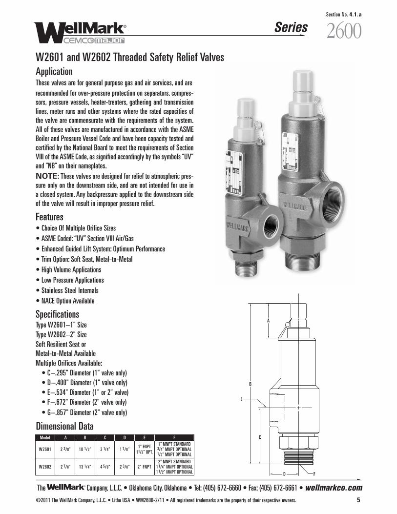
The Company, L.L.C. • Oklahoma City, Oklahoma • Tel: (405) 672-6660 • Fax: (405) 672-6661 • wellmarkco.com
Series 2600Section No. 4.1.a
©2011 The WellMark Company, L.L.C. • Litho USA • WM2600-2/11 • All registered trademarks are the property of their respective owners. 5
Model A B C D E F
1" FNPT 1" MNPT STANDARDW2601 2 3/8" 10 1/2" 3 1/4" 1 7/8" 3/4" MNPT OPTIONAL
11/2" OPT. 1/2" MNPT OPTIONAL
2" MNPT STANDARDW2602 2 7/8" 13 1/4" 4 5/8" 2 3/8" 2" FNPT 11/4" MNPT OPTIONAL
11/2" MNPT OPTIONAL
W2601 and W2602 Threaded Safety Relief ValvesApplicationThese valves are for general purpose gas and air services, and arerecommended for over-pressure protection on separators, compres-sors, pressure vessels, heater-treaters, gathering and transmissionlines, meter runs and other systems where the rated capacities ofthe valve are commensurate with the requirements of the system.All of these valves are manufactured in accordance with the ASMEBoiler and Pressure Vessel Code and have been capacity tested andcertified by the National Board to meet the requirements of SectionVIII of the ASME Code, as signified accordingly by the symbols “UV”and “NB” on their nameplates.NOTE: These valves are designed for relief to atmospheric pres-sure only on the downstream side, and are not intended for use ina closed system. Any backpressure applied to the downstream sideof the valve will result in improper pressure relief.
Features• Choice Of Multiple Orifice Sizes• ASME Coded: “UV” Section VIII Air/Gas• Enhanced Guided Lift System: Optimum Performance• Trim Option: Soft Seat, Metal-to-Metal • High Volume Applications• Low Pressure Applications• Stainless Steel Internals• NACE Option Available
SpecificationsType W2601–1" SizeType W2602–2" SizeSoft Resilient Seat or Metal-to-Metal AvailableMultiple Orifices Available:
• C–.295" Diameter (1" valve only)• D–.400" Diameter (1" valve only)• E–.534" Diameter (1" or 2" valve)• F–.672" Diameter (2" valve only)• G–.857" Diameter (2" valve only)
Dimensional Data
A
B
C
E
D F
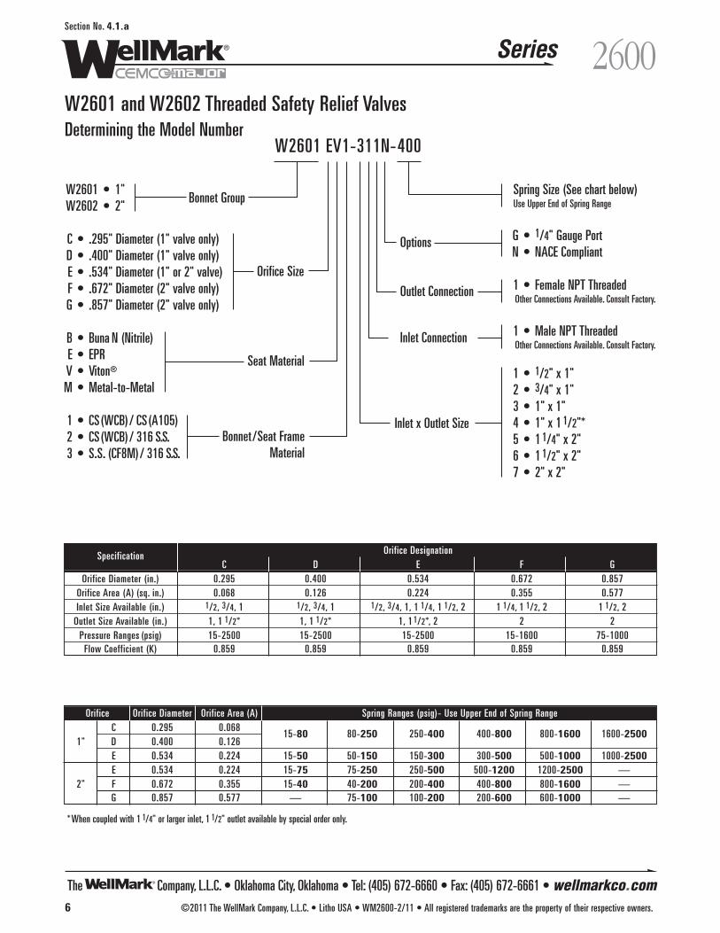
The Company, L.L.C. • Oklahoma City, Oklahoma • Tel: (405) 672-6660 • Fax: (405) 672-6661 • wellmarkco.com
Series 2600Section No. 4.1.a
6 ©2011 The WellMark Company, L.L.C. • Litho USA • WM2600-2/11 • All registered trademarks are the property of their respective owners.
Options
W2601 • 1"W2602 • 2"
C • .295" Diameter (1" valve only) D • .400" Diameter (1" valve only)E • .534" Diameter (1" or 2" valve)F • .672" Diameter (2" valve only)G • .857" Diameter (2" valve only)
B • Buna N (Nitrile)E • EPR V • Viton®
M • Metal-to-Metal
1 • CS(WCB)/ CS(A105)2 • CS(WCB)/ 316 S.S.3 • S.S. (CF8M)/ 316 S.S.
Determining the Model NumberW2601 and W2602 Threaded Safety Relief Valves
Spring Size (See chart below) Use Upper End of Spring Range
G • 1/4" Gauge Port N • NACE Compliant
1 • Female NPT ThreadedOther Connections Available. Consult Factory.
1 • Male NPT ThreadedOther Connections Available. Consult Factory.
1 • 1/2" x 1" 2 • 3/4" x 1" 3 • 1" x 1"4 • 1" x 1 1/2"*5 • 1 1/4" x 2"6 • 1 1/2" x 2"7 • 2" x 2"
W2601 EV1-311N-400
Seat Material
Orifice Size
Bonnet Group
Outlet Connection
Inlet Connection
Bonnet /Seat FrameMaterial
Inlet x Outlet Size
*When coupled with 1 1/4" or larger inlet, 1 1/2" outlet available by special order only.
Orifice Orifice Diameter Orifice Area (A) Spring Ranges (psig)- Use Upper End of Spring RangeC 0.295 0.068
15-80 80-250 250-400 400-800 800-1600 1600-25001" D 0.400 0.126
E 0.534 0.224 15-50 50-150 150-300 300-500 500-1000 1000-2500E 0.534 0.224 15-75 75-250 250-500 500-1200 1200-2500 —
2" F 0.672 0.355 15-40 40-200 200-400 400-800 800-1600 —G 0.857 0.577 — 75-100 100-200 200-600 600-1000 —
Specification Orifice DesignationC D E F G
Orifice Diameter (in.) 0.295 0.400 0.534 0.672 0.857Orifice Area (A) (sq. in.) 0.068 0.126 0.224 0.355 0.577Inlet Size Available (in. ) 1/2, 3/4, 1 1/2, 3/4, 1 1/2, 3/4, 1, 1 1/4, 1 1/2, 2 1 1/4, 1 1/2, 2 1 1/2, 2
Outlet Size Available (in. ) 1, 1 1/2* 1, 1 1/2* 1, 1 1/2*, 2 2 2Pressure Ranges (psig) 15-2500 15-2500 15-2500 15-1600 75-1000
Flow Coefficient (K) 0.859 0.859 0.859 0.859 0.859
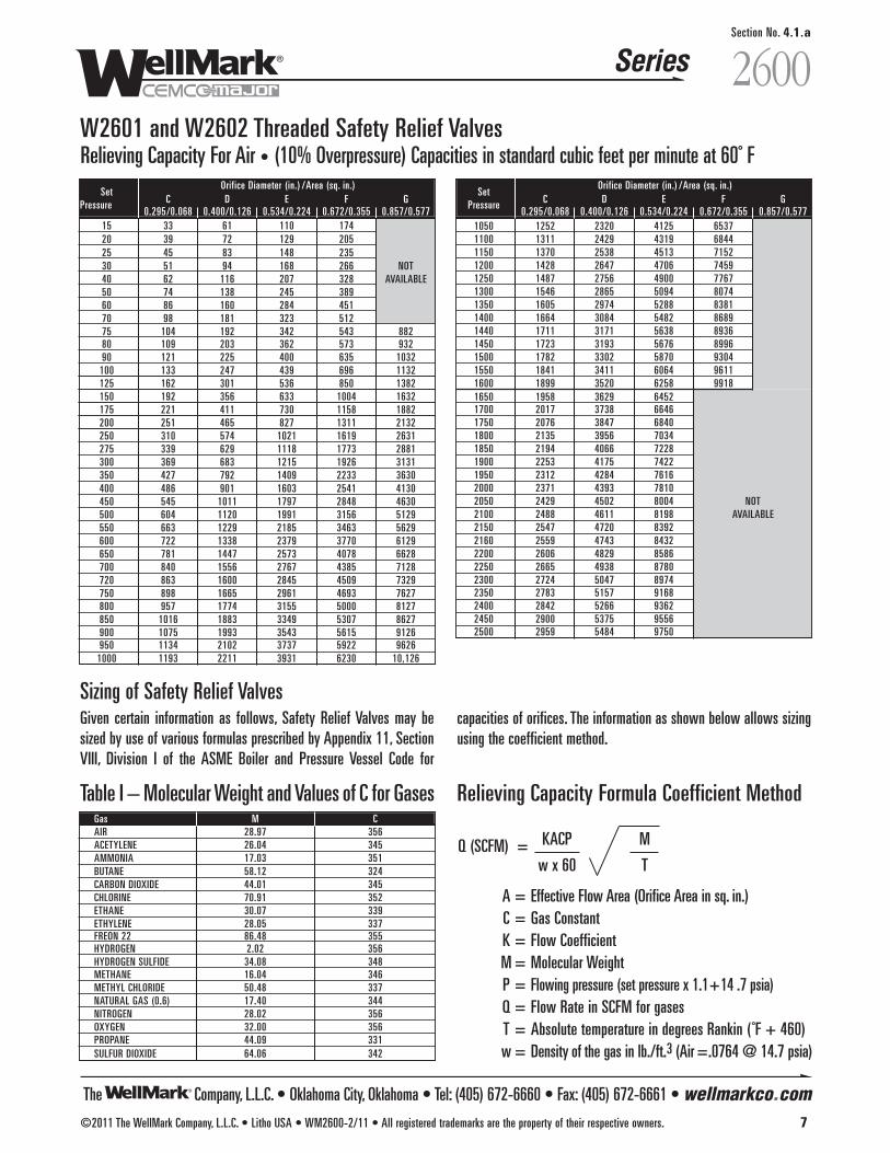
Series 2600Section No. 4.1.a
The Company, L.L.C. • Oklahoma City, Oklahoma • Tel: (405) 672-6660 • Fax: (405) 672-6661 • wellmarkco.com©2011 The WellMark Company, L.L.C. • Litho USA • WM2600-2/11 • All registered trademarks are the property of their respective owners. 7
Relieving Capacity For Air • (10% Overpressure) Capacities in standard cubic feet per minute at 60˚ F
Relieving Capacity Formula Coefficient Method
Q (SCFM) =
A = Effective Flow Area (Orifice Area in sq. in.)C = Gas ConstantK = Flow CoefficientM = Molecular WeightP = Flowing pressure (set pressure x 1.1+14 .7 psia)Q = Flow Rate in SCFM for gasesT = Absolute temperature in degrees Rankin ( ˚F + 460)w = Density of the gas in lb./ft.3 (Air =.0764 @ 14.7 psia)
KACP
w x 60
M
T
Sizing of Safety Relief ValvesGiven certain information as follows, Safety Relief Valves may besized by use of various formulas prescribed by Appendix 11, SectionVIII, Division I of the ASME Boiler and Pressure Vessel Code for
Table I – Molecular Weight and Values of C for GasesGas M CAIR 28.97 356ACETYLENE 26.04 345AMMONIA 17.03 351BUTANE 58.12 324CARBON DIOXIDE 44.01 345CHLORINE 70.91 352ETHANE 30.07 339ETHYLENE 28.05 337FREON 22 86.48 355HYDROGEN 2.02 356HYDROGEN SULFIDE 34.08 348METHANE 16.04 346METHYL CHLORIDE 50.48 337NATURAL GAS (0.6) 17.40 344NITROGEN 28.02 356OXYGEN 32.00 356PROPANE 44.09 331SULFUR DIOXIDE 64.06 342
W2601 and W2602 Threaded Safety Relief Valves
SetOrifice Diameter (in.) /Area (sq. in.)
C D E F GPressure0.295/0.068 0.400/0.126 0.534/0.224 0.672/0.355 0.857/0.577
15 33 61 110 17420 39 72 129 20525 45 83 148 23530 51 94 168 266 NOT40 62 116 207 328 AVAILABLE50 74 138 245 38960 86 160 284 45170 98 181 323 51275 104 192 342 543 88280 109 203 362 573 93290 121 225 400 635 1032
100 133 247 439 696 1132125 162 301 536 850 1382150 192 356 633 1004 1632175 221 411 730 1158 1882200 251 465 827 1311 2132250 310 574 1021 1619 2631275 339 629 1118 1773 2881300 369 683 1215 1926 3131350 427 792 1409 2233 3630400 486 901 1603 2541 4130450 545 1011 1797 2848 4630500 604 1120 1991 3156 5129550 663 1229 2185 3463 5629600 722 1338 2379 3770 6129650 781 1447 2573 4078 6628700 840 1556 2767 4385 7128720 863 1600 2845 4509 7329750 898 1665 2961 4693 7627800 957 1774 3155 5000 8127850 1016 1883 3349 5307 8627900 1075 1993 3543 5615 9126950 1134 2102 3737 5922 9626
1000 1193 2211 3931 6230 10,126
capacities of orifices. The information as shown below allows sizingusing the coefficient method.
SetOrifice Diameter (in.) /Area (sq. in.)
C D E F GPressure0.295/0.068 0.400/0.126 0.534/0.224 0.672/0.355 0.857/0.577
1050 1252 2320 4125 65371100 1311 2429 4319 68441150 1370 2538 4513 71521200 1428 2647 4706 74591250 1487 2756 4900 77671300 1546 2865 5094 80741350 1605 2974 5288 83811400 1664 3084 5482 86891440 1711 3171 5638 89361450 1723 3193 5676 89961500 1782 3302 5870 93041550 1841 3411 6064 96111600 1899 3520 6258 99181650 1958 3629 64521700 2017 3738 66461750 2076 3847 68401800 2135 3956 70341850 2194 4066 72281900 2253 4175 74221950 2312 4284 76162000 2371 4393 78102050 2429 4502 8004 NOT2100 2488 4611 8198 AVAILABLE2150 2547 4720 83922160 2559 4743 84322200 2606 4829 85862250 2665 4938 87802300 2724 5047 89742350 2783 5157 91682400 2842 5266 93622450 2900 5375 95562500 2959 5484 9750

The Company, L.L.C. • Oklahoma City, Oklahoma • Tel: (405) 672-6660 • Fax: (405) 672-6661 • wellmarkco.com
Series 2600Section No. 4.1.a
8 ©2011 The WellMark Company, L.L.C. • Litho USA • WM2600-2/11 • All registered trademarks are the property of their respective owners.
Item Description Material Qty. Part No.1 BONNET SA-216 GR. WCB CS 1 40996
11/4" SA-105 CS 1 310612 SEAT FRAME 11/2" SA-105 CS 1 31062
2" SA-105 CS 1 31056"E" ORIFICE SA-276 S.S. 1 21274
3 SEAT "F" ORIFICE SA-276 S.S. 1 21259"G" ORIFICE SA-276 S.S. 1 21265"E" ORIFICE SA-276 S.S. 1 21273
4 PLUG "F" ORIFICE SA-276 S.S. 1 21260"G" ORIFICE SA-276 S.S. 1 21267"E" ORIFICE VITON® 1 11182
5 O-RING "F" ORIFICE VITON® 1 11183"G" ORIFICE VITON® 1 11186"E" ORIFICE SA-276 S.S. 1 21275
6 O-RING HOLDER "F" ORIFICE SA-276 S.S. 1 21261"G" ORIFICE SA-276 S.S. 1 21271"E" ORIFICE SA-351 S.S. 1 21278
7 PLUG GUIDE "F" ORIFICE SA-351 S.S. 1 21258"G" ORIFICE SA-351 S.S. 1 21376
8 SPRING GUIDE SA-29 CS 2 2126315-75# 302 S.S. 1 10296
75-250# 302 S.S. 1 10297SPRING FOR E 250-500# 302 S.S. 1 10298
500-1200# 302 S.S. 1 103011200-2500# 17-7 S.S. 1 10304
15-40# 302 S.S. 1 1029640-200# 302 S.S. 1 10297
9 SPRING FOR F 200-400# 302 S.S. 1 10298400-800# 302 S.S. 1 10301
800-1600# 17-7 S.S. 1 1030475-100# 302 S.S. 1 10297
100-200# 302 S.S. 1 10298SPRING FOR G 200-600# 302 S.S. 1 10301
600-1000# 17-7 S.S. 1 1030410 ADJUSTING SCREW 307 CS 1 2126411 O-RING VITON® 1 1064512 O-RING VITON® 1 1037913 SEAL WASHER S.S./BUNA-N 1 1057814 JAM NUT STEEL 1 1059815 CAP ALUMINUM 1 2121216 GUIDE SA-29 CS 1 2127917 GUIDE STEM SA-29 CS 1 21280
18 SCREW"E" ORIFICE 18-8 S.S. 1 11184
"F", "G" ORIFICE 18-8 S.S. 1 1118519 O-RING VITON® 1 1027820* NAMEPLATE ALUMINUM 1 1106621* DRIVE SCREW 18-8 S.S. 4 1007522 SEAL WIRE & LEAD STEEL & LEAD 1 10178
*Not ShownNote: Optional Seal Materials Available. Consult Factory.
Item Description Material Qty. Part No.1 BONNET SA-216 GR. WCB CS 1 40986
1/2" SA-105 CS 1 212932 SEAT FRAME 3/4" SA-105 CS 1 21294
1" SA-105 CS 1 21222"C" ORIFICE SA-276 S.S. 1 21223
3 SEAT "D" ORIFICE SA-276 S.S. 1 21242"E" ORIFICE SA-276 S.S. 1 21283
4 PLUG "C", "D" ORIFICE SA-276 S.S. 1 21224"E" ORIFICE SA-276 S.S. 1 21282
5 O-RING "C", "D" ORIFICE VITON® 1 11180
"E" ORIFICE VITON® 1 11182
6 O-RING HOLDER"C", "D"ORIFICE SA-276 S.S. 1 21226
"E" ORIFICE SA-276 S.S. 1 21275
7 PLUG GUIDE"C", "D" ORIFICE SA-351 S.S. 1 21225
"E" ORIFICE SA-351 S.S. 1 212848 SPRING GUIDE SA-29 CS 2 21227
15-80# 302 S.S. 1 1118880-250# 302 S.S. 1 11189
SPRING FOR C OR D250-400# 302 S.S. 1 11190400-800# 302 S.S. 1 11192
800-1600# 17-7 S.S. 1 11194
91600-2500# 17-7 S.S. 1 11195
15-50# 302 S.S. 1 1118850-150# 302 S.S. 1 11189
SPRING FOR E150-300# 302 S.S. 1 11190300-500# 302 S.S. 1 11192
500-1000# 17-7 S.S. 1 111941000-2500# 17-7 S.S. 1 11195
10 ADJUSTING SCREW 307 CS 1 2122911 O-RING VITON® 1 1118112 O-RING VITON® 1 1040213 SEAL WASHER S.S./BUNA-N 1 1057814 JAM NUT STEEL 1 1017415 CAP ALUMINUM 1 2121116 GUIDE SA-29 CS 1 2127917 GUIDE STEM SA-29 CS 1 21292
18 SCREW"C", "D" ORIFICE 18-8 S.S. 1 10001
"E" ORIFICE 18-8 S.S. 1 1118419 O-RING VITON® 1 05000-022320* NAMEPLATE ALUMINUM 1 1106621* DRIVE SCREW 18-8 S.S. 4 1007522 SEAL WIRE & LEAD STEEL & LEAD 1 10178
*Not ShownNote: Optional Seal Materials Available. Consult Factory.
W2601 and W2602 Threaded Safety Relief Valves
Parts List, W2601
Parts List, W2602
15
22
8
1 9
178
10
19
14
13
12
16 4
56
18 7
311
2
See Details
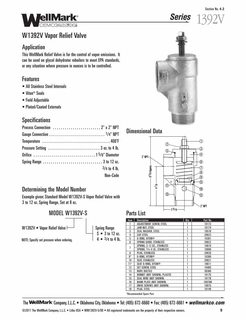
The Company, L.L.C. • Oklahoma City, Oklahoma • Tel: (405) 672-6660 • Fax: (405) 672-6661 • wellmarkco.com
Series
©2011 The WellMark Company, L.L.C. • Litho USA • WM1392V-5/09 • All registered trademarks are the property of their respective owners. 9
1392V
Section No. 4.2
W1392V Vapor Relief Valve
ApplicationThis WellMark Relief Valve is for the control of vapor emissions. Itcan be used on glycol dehydrator reboilers to meet EPA standards,or any situation where pressure in ounces is to be controlled.
Features• All Stainless Steel Internals
• Viton® Seals
• Field Adjustable
• Plated/Coated Externals
SpecificationsProcess Connection . . . . . . . . . . . . . . . . . . . . . . . . 2" x 2" NPT
Gauge Connection . . . . . . . . . . . . . . . . . . . . . . . . . . . . 1/4" NPT
Temperature . . . . . . . . . . . . . . . . . . . . . . . . . . . . . . . . . . 400˚F
Pressure Setting . . . . . . . . . . . . . . . . . . . . . . . . . . 3 oz. to 4 lb.
Orifice . . . . . . . . . . . . . . . . . . . . . . . . . . . . . . . 1 5/8" Diameter
Spring Range . . . . . . . . . . . . . . . . . . . . . . . . . . . . . . 3 to 12 oz.3/4 to 4 lb.
Non-Code
Determining the Model NumberExample given: Standard Model W1392V-S Vapor Relief Valve with3 to 12 oz. Spring Range, Set at 8 oz.
Spring RangeS • 3 to 12 oz.4 • 3/4 to 4 lb.
W1392V • Vapor Relief Valve
NOTE: Specify set pressure when ordering.
MODEL W1392V-S
4 7 /8
2 9/16
8 5 /8 A
pprox
.
2
5
11
13
1
3
4
6
7
8
9
12
10
12
2" NPT
2" NPT
Dimensional Data
Parts ListItem Description Qty. Part No.1 ADJUSTMENT SCREW, STEEL 1 101732 JAM NUT, STEEL 1 101743 SEAL WASHER, STEEL 1 105784 CAP, STEEL 1 206235 O-RING, VITON® 1 103816 SPRING GUIDE, STAINLESS 1 20622
7SPRING, 3-12 OZ., STAINLESS 1 10610SPRING, 3/4-4 LB., STAINLESS 1 10680
8 PLUG, STAINLESS 1 206209* O-RING, VITON® 1 1038010 SEAT, STAINLESS 1 2062111* SEAT O-RING, VITON® 1 1061112 SET SCREW, STEEL 1 1048513 BODY, DUCTILE 1 3036014 BONNET (NOT SHOWN), PLASTIC 1 1017515 SEAL WIRE (NOT SHOWN) 1 1017816 NAME PLATE (NOT SHOWN) 1 10076B17 DRIVE SCREWS (NOT SHOWN) 1 1007518 PLUG, STEEL 1 10149
*Recommended Spare Part
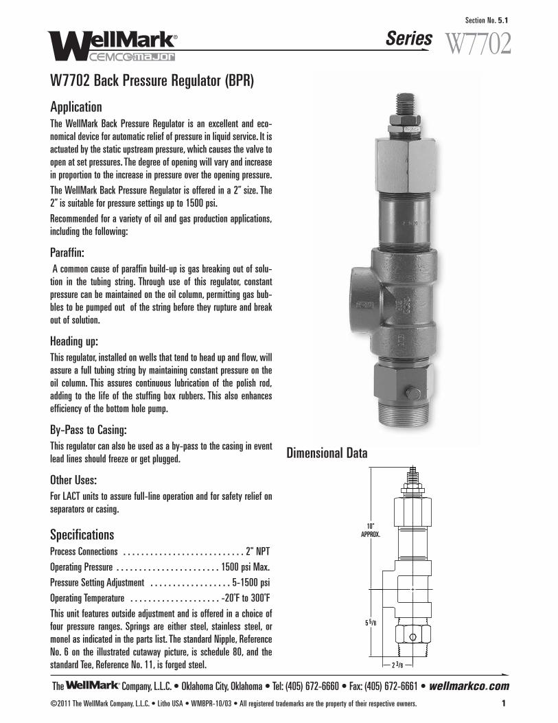
The Company, L.L.C. • Oklahoma City, Oklahoma • Tel: (405) 672-6660 • Fax: (405) 672-6661 • wellmarkco.com
Series
©2011 The WellMark Company, L.L.C. • Litho USA • WMBPR-10/03 • All registered trademarks are the property of their respective owners. 1
W7702Section No. 5.1
W7702 Back Pressure Regulator (BPR)
ApplicationThe WellMark Back Pressure Regulator is an excellent and eco-nomical device for automatic relief of pressure in liquid service. It isactuated by the static upstream pressure, which causes the valve toopen at set pressures. The degree of opening will vary and increasein proportion to the increase in pressure over the opening pressure.
The WellMark Back Pressure Regulator is offered in a 2” size. The2” is suitable for pressure settings up to 1500 psi.
Recommended for a variety of oil and gas production applications,including the following:
Paraffin:A common cause of paraffin build-up is gas breaking out of solu-
tion in the tubing string. Through use of this regulator, constantpressure can be maintained on the oil column, permitting gas bub-bles to be pumped out of the string before they rupture and breakout of solution.
Heading up:This regulator, installed on wells that tend to head up and flow, willassure a full tubing string by maintaining constant pressure on theoil column. This assures continuous lubrication of the polish rod,adding to the life of the stuffing box rubbers. This also enhancesefficiency of the bottom hole pump.
By-Pass to Casing:This regulator can also be used as a by-pass to the casing in eventlead lines should freeze or get plugged.
Other Uses:For LACT units to assure full-line operation and for safety relief onseparators or casing.
SpecificationsProcess Connections . . . . . . . . . . . . . . . . . . . . . . . . . . . 2" NPT
Operating Pressure . . . . . . . . . . . . . . . . . . . . . . . 1500 psi Max.
Pressure Setting Adjustment . . . . . . . . . . . . . . . . . . 5-1500 psi
Operating Temperature . . . . . . . . . . . . . . . . . . . . -20˚F to 300˚F
This unit features outside adjustment and is offered in a choice offour pressure ranges. Springs are either steel, stainless steel, ormonel as indicated in the parts list. The standard Nipple, ReferenceNo. 6 on the illustrated cutaway picture, is schedule 80, and thestandard Tee, Reference No. 11, is forged steel.
5 5/8
10"APPROX.
2 3/8
Dimensional Data
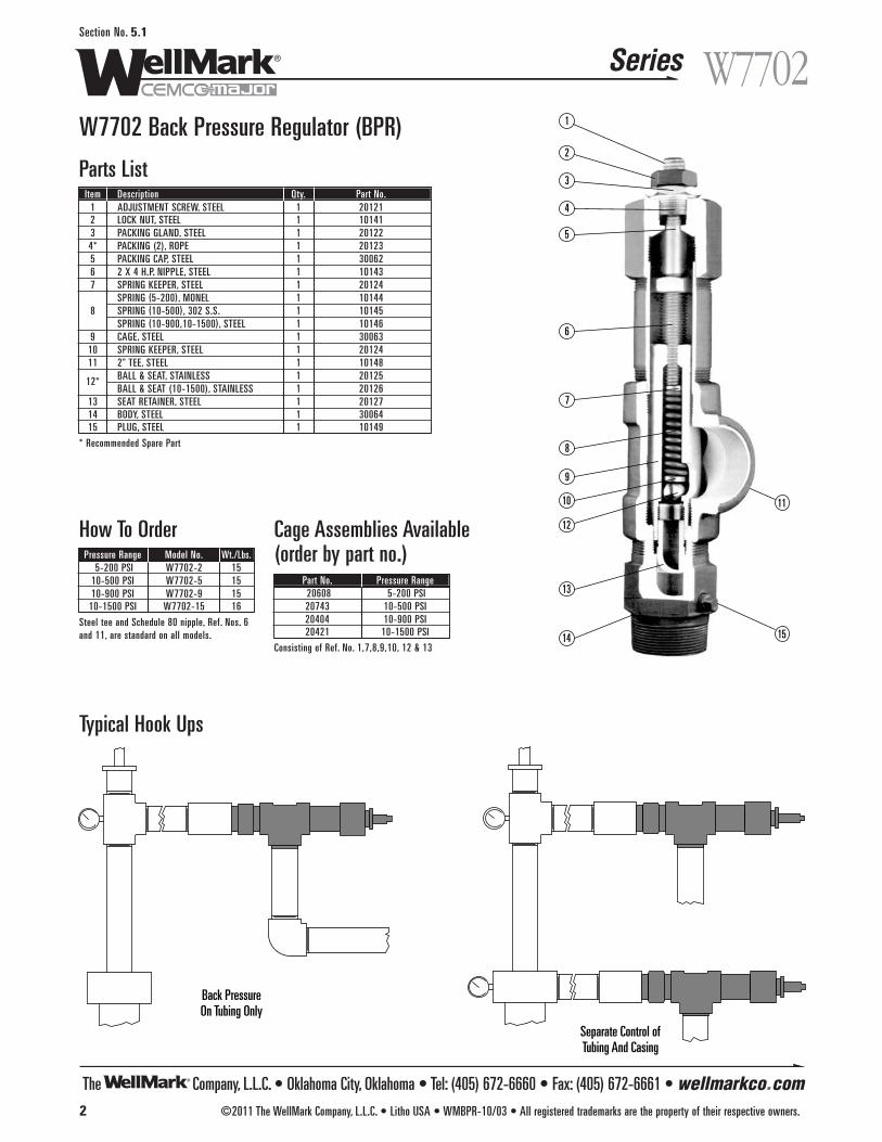
The Company, L.L.C. • Oklahoma City, Oklahoma • Tel: (405) 672-6660 • Fax: (405) 672-6661 • wellmarkco.com
Series
2 ©2011 The WellMark Company, L.L.C. • Litho USA • WMBPR-10/03 • All registered trademarks are the property of their respective owners.
W7702Section No. 5.1
W7702 Back Pressure Regulator (BPR)
How To Order
Typical Hook Ups
1
2
3
4
5
6
7
8
9
10
12
13
14 15
11
Pressure Range Model No. Wt./Lbs.5-200 PSI W7702-2 15
10-500 PSI W7702-5 1510-900 PSI W7702-9 15
10-1500 PSI W7702-15 16
Steel tee and Schedule 80 nipple, Ref. Nos. 6 and 11, are standard on all models.
Cage Assemblies Available(order by part no.)
Part No. Pressure Range20608 5-200 PSI20743 10-500 PSI20404 10-900 PSI20421 10-1500 PSI
Consisting of Ref. No. 1,7,8,9,10, 12 & 13
Parts ListItem Description Qty. Part No.
1 ADJUSTMENT SCREW, STEEL 1 201212 LOCK NUT, STEEL 1 101413 PACKING GLAND, STEEL 1 201224* PACKING (2), ROPE 1 201235 PACKING CAP, STEEL 1 300626 2 X 4 H.P. NIPPLE, STEEL 1 101437 SPRING KEEPER, STEEL 1 20124
SPRING (5-200), MONEL 1 101448 SPRING (10-500), 302 S.S. 1 10145
SPRING (10-900,10-1500), STEEL 1 101469 CAGE, STEEL 1 30063
10 SPRING KEEPER, STEEL 1 2012411 2" TEE, STEEL 1 10148
12* BALL & SEAT, STAINLESS 1 20125BALL & SEAT (10-1500), STAINLESS 1 20126
13 SEAT RETAINER, STEEL 1 2012714 BODY, STEEL 1 3006415 PLUG, STEEL 1 10149
* Recommended Spare Part
Back PressureOn Tubing Only
Separate Control ofTubing And Casing
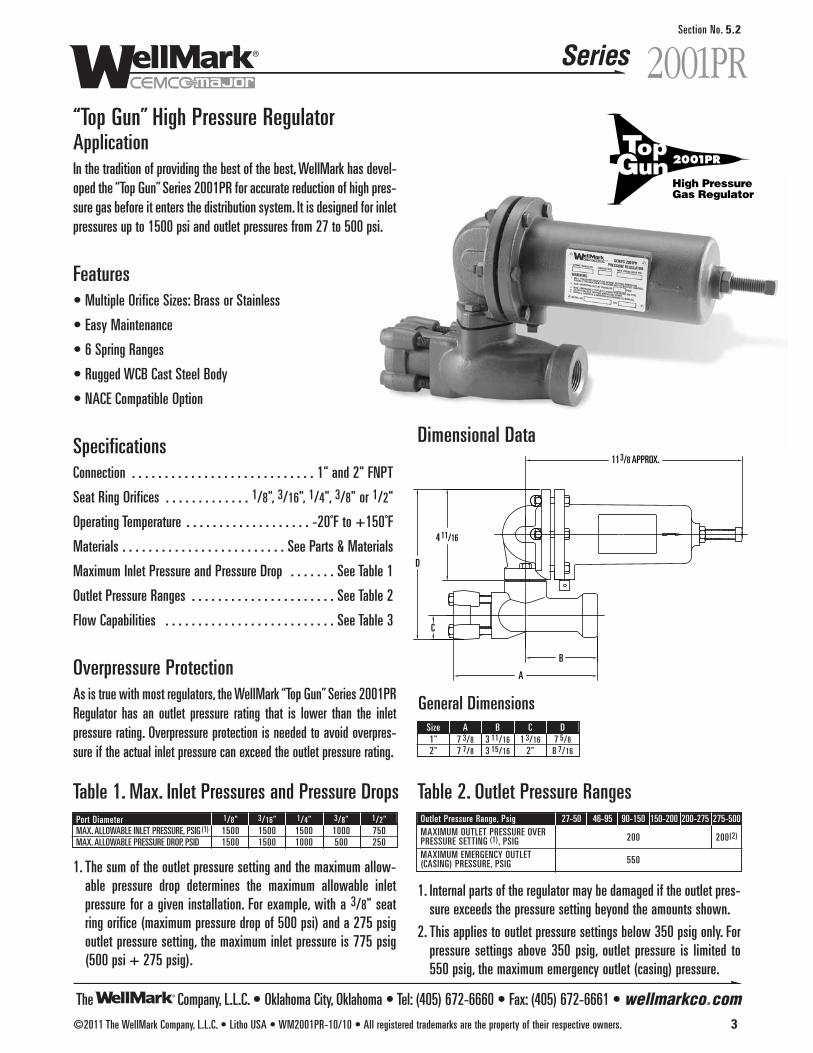
The Company, L.L.C. • Oklahoma City, Oklahoma • Tel: (405) 672-6660 • Fax: (405) 672-6661 • wellmarkco.com
Series 2001PR
©2011 The WellMark Company, L.L.C. • Litho USA • WM2001PR-10/10 • All registered trademarks are the property of their respective owners. 3
Section No. 5.2
“Top Gun” High Pressure RegulatorApplicationIn the tradition of providing the best of the best, WellMark has devel-oped the “Top Gun” Series 2001PR for accurate reduction of high pres-sure gas before it enters the distribution system. It is designed for inletpressures up to 1500 psi and outlet pressures from 27 to 500 psi.
Features• Multiple Orifice Sizes: Brass or Stainless
• Easy Maintenance
• 6 Spring Ranges
• Rugged WCB Cast Steel Body
• NACE Compatible Option
SpecificationsConnection . . . . . . . . . . . . . . . . . . . . . . . . . . . . 1" and 2" FNPT
Seat Ring Orifices . . . . . . . . . . . . . 1/8", 3/16", 1/4", 3/8" or 1/2"
Operating Temperature . . . . . . . . . . . . . . . . . . . -20˚F to +150˚F
Materials . . . . . . . . . . . . . . . . . . . . . . . . . See Parts & Materials
Maximum Inlet Pressure and Pressure Drop . . . . . . . See Table 1
Outlet Pressure Ranges . . . . . . . . . . . . . . . . . . . . . . See Table 2
Flow Capabilities . . . . . . . . . . . . . . . . . . . . . . . . . . See Table 3
Overpressure Protection As is true with most regulators, the WellMark “Top Gun” Series 2001PRRegulator has an outlet pressure rating that is lower than the inletpressure rating. Overpressure protection is needed to avoid overpres-sure if the actual inlet pressure can exceed the outlet pressure rating.
4 11/16
11 3/8 APPROX.
D
C
B
A
Dimensional Data
1. The sum of the outlet pressure setting and the maximum allow-able pressure drop determines the maximum allowable inletpressure for a given installation. For example, with a 3/8" seatring orifice (maximum pressure drop of 500 psi) and a 275 psigoutlet pressure setting, the maximum inlet pressure is 775 psig(500 psi + 275 psig).
1. Internal parts of the regulator may be damaged if the outlet pres-sure exceeds the pressure setting beyond the amounts shown.
2. This applies to outlet pressure settings below 350 psig only. Forpressure settings above 350 psig, outlet pressure is limited to550 psig, the maximum emergency outlet (casing) pressure.
High PressureGas Regulator
2001PR
Table 1. Max. Inlet Pressures and Pressure DropsPort Diameter 1/8" 3/16" 1/4" 3/8" 1/2"MAX. ALLOWABLE INLET PRESSURE, PSIG (1) 1500 1500 1500 1000 750MAX. ALLOWABLE PRESSURE DROP, PSID 1500 1500 1000 500 250
Table 2. Outlet Pressure RangesOutlet Pressure Range, Psig 27-50 46-95 90-150 150-200 200-275 275-500MAXIMUM OUTLET PRESSURE OVER 200 200(2)PRESSURE SETTING (1), PSIGMAXIMUM EMERGENCY OUTLET 550(CASING) PRESSURE, PSIG
General DimensionsSize A B C D1" 7 3/8 3 11/16 1 3/16 7 5/82" 7 7/8 3 15/16 2" 8 7/16
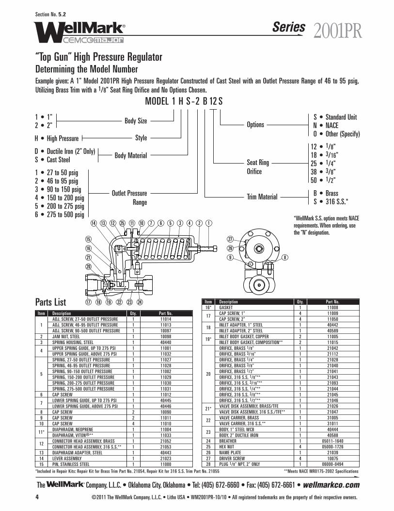
The Company, L.L.C. • Oklahoma City, Oklahoma • Tel: (405) 672-6660 • Fax: (405) 672-6661 • wellmarkco.com
Series
1243567101125121314
15
16
20
17 18 22 23 2419
21
27
26
9 8
4 ©2011 The WellMark Company, L.L.C. • Litho USA • WM2001PR-10/10 • All registered trademarks are the property of their respective owners.
2001PRSection No. 5.2
“Top Gun” High Pressure RegulatorDetermining the Model NumberExample given: A 1" Model 2001PR High Pressure Regulator Constructed of Cast Steel with an Outlet Pressure Range of 46 to 95 psig,Utilizing Brass Trim with a 1/8" Seat Ring Orifice and No Options Chosen.
S • Standard UnitN • NACEO • Other (Specify)
12 • 1/8"18 • 3/16"25 • 1/4"38 • 3/8"50 • 1/2"
B • BrassS • 316 S.S.*
1 • 1"2 • 2"
H • High Pressure
D • Ductile Iron (2” Only)S • Cast Steel
1 • 27 to 50 psig2 • 46 to 95 psig3 • 90 to 150 psig4 • 150 to 200 psig5 • 200 to 275 psig6 • 275 to 500 psig
MODEL 1 H S -2 B 12 S
Body Size
Style
Body Material
Outlet PressureRange
Seat RingOrifice
Options
Trim Material
*WellMark S.S. option meets NACErequirements. When ordering, usethe “N” designation.
Parts ListItem Description Qty. Part No.
ADJ. SCREW, 27-50 OUTLET PRESSURE 1 110141 ADJ. SCREW, 46-95 OUTLET PRESSURE 1 11013
ADJ. SCREW, 90-500 OUTLET PRESSURE 1 100972 JAM NUT, STEEL 1 100983 SPRING HOUSING, STEEL 1 40440
4 UPPER SPRING GUIDE, UP TO 275 PSI 1 11001UPPER SPRING GUIDE, ABOVE 275 PSI 1 11032SPRING, 27-50 OUTLET PRESSURE 1 11027SPRING, 46-95 OUTLET PRESSURE 1 11028
5 SPRING, 90-150 OUTLET PRESSURE 1 11002SPRING, 150-200 OUTLET PRESSURE 1 11029SPRING, 200-275 OUTLET PRESSURE 1 11030SPRING, 275-500 OUTLET PRESSURE 1 11031
6 CAP SCREW 1 11012
7 LOWER SPRING GUIDE, UP TO 275 PSI 1 40445LOWER SPRING GUIDE, ABOVE 275 PSI 1 40446
8 CAP SCREW 2 100909 CAP SCREW 2 11011
10 CAP SCREW 4 11010
11* DIAPHRAGM, NEOPRENE 1 11004DIAPHRAGM, VITON®** 1 11033
12 CONNECTOR HEAD ASSEMBLY, BRASS 1 21052CONNECTOR HEAD ASSEMBLY, 316 S.S.** 1 21053
13 DIAPHRAGM ADAPTER, STEEL 1 4044314 LEVER ASSEMBLY 1 2102315 PIN, STAINLESS STEEL 1 11000
Item Description Qty. Part No.16* GASKET 1 11008
17 CAP SCREW, 1" 4 11009CAP SCREW, 2" 4 11050
18 INLET ADAPTER, 1" STEEL 1 40442INLET ADAPTER, 2" STEEL 1 40589
19* INLET BODY GASKET, COPPER 2 11005INLET BODY GASKET, COMPOSITION** 2 11015ORIFICE, BRASS 1/8" 1 21042ORIFICE, BRASS 3/16" 1 21112ORIFICE, BRASS 1/4" 1 21028ORIFICE, BRASS 3/8" 1 21040
20 ORIFICE, BRASS 1/2" 1 21041ORIFICE, 316 S.S, 1/8"** 1 21043ORIFICE, 316 S.S, 3/16"** 1 21093ORIFICE, 316 S.S, 1/4"** 1 21044ORIFICE, 316 S.S, 3/8"** 1 21045ORIFICE, 316 S.S, 1/2"** 1 21046
21* VALVE DISK ASSEMBLY, BRASS/TFE 1 21026VALVE DISK ASSEMBLY, 316 S.S./TFE** 1 21047
22 VALVE CARRIER, BRASS 1 31005VALVE CARRIER, 316 S.S.** 1 31011
23 BODY, 1" STEEL WCB 1 40444BODY, 2" DUCTILE IRON 1 40588
24 BREATHER 1 05011-164025 HEX NUT 4 05000-172626 NAME PLATE 1 2103927 DRIVER SCREW 4 1007528 PLUG 1/8" NPT, 2" ONLY 1 06000-0494
*Included in Repair Kits: Repair Kit for Brass Trim Part No. 21054, Repair Kit for 316 S.S. Trim Part No. 21055 **Meets NACE MR0175-2002 Specifications
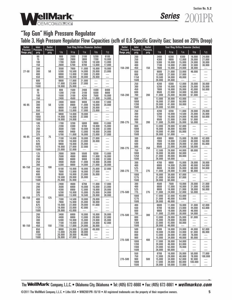
The Company, L.L.C. • Oklahoma City, Oklahoma • Tel: (405) 672-6660 • Fax: (405) 672-6661 • wellmarkco.com
Series 2001PR
©2011 The WellMark Company, L.L.C. • Litho USA • WM2001PR-10/10 • All registered trademarks are the property of their respective owners. 5
Section No. 5.2
“Top Gun” High Pressure RegulatorTable 3. High Pressure Regulator Flow Capacities (scfh of 0.6 Specific Gravity Gas; based on 20% Droop)
Outlet Inlet Outlet Seat Ring Orifice Diameter (Inches)Pressure Pressure, Pressure,
Range, psig psig psig 1/8 3/16 1/4 3/8 1/2
60 900 2000 3100 5200 810075 1300 2800 3800 7200 10,000
100 1700 3500 5700 10,500 13,000150 2600 5700 8700 13,000 17,000200 3500 7800 11,000 16,000 19,000
27-50 300 50 5300 10,500 14,000 20,000 23,000400 6900 13,000 17,000 23,000 —550 9600 16,000 20,000 26,000 —600 9800 17,000 21,000 — —
1050 17,000 23,000 27,000 — —1500 19,000 25,000 — — —
60 800 1500 2400 4300 640075 1200 2100 3100 5500 8000
100 1500 3100 4200 7500 10,000150 2400 4500 6700 11,000 14,000200 3400 6600 9400 14,000 17,000
46-95 300 50 5200 8900 11,000 16,000 20,000400 6800 11,000 15,000 20,000 —550 9500 13,000 17,000 23,000 —600 9800 14,000 19,000 — —
1050 14,000 19,000 22,000 — —1500 18,000 24,000 — — —100 1700 3200 5000 8000 13,000125 2200 4300 6700 10,000 15,000200 3500 7300 10,000 16,000 22,000250 4400 9400 13,000 19,000 24,000325 5700 11,000 16,000 23,000 27,000
46-95 400 75 7100 14,000 19,000 27,000 —575 9700 18,000 23,000 30,000 —600 9900 19,000 25,000 — —
1075 18,000 27,000 32,000 — —1500 23,000 32,000 — — —
125 2000 3600 5500 9200 13,000150 2500 4600 6800 11,000 16,000200 3600 6600 9400 13,000 22,000250 4400 8500 11,000 18,000 26,000300 5300 9800 14,000 21,000 30,000
90-150 350 100 6100 10,000 16,000 25,000 32,000400 7000 13,000 18,000 27,000 —600 9500 18,000 23,000 35,000 —
1100 19,500 28,000 35,000 — —1500 25,000 35,000 — — —
150 2400 4600 6700 11,000 17,000200 3500 6800 10,000 15,000 23,000250 4300 8900 12,000 19,000 29,000300 5200 10,000 15,000 25,000 34,000375 6600 13,000 18,500 28,000 39,000
90-150 400 125 7300 14,500 19,000 29,000 —500 7900 15,000 25,000 36,000 —625 10,000 22,000 29,000 41,000 —
1125 18,000 33,000 42,000 — —1500 26,000 43,000 — — —
200 3400 6800 10,000 16,000 26,000250 4400 8800 13,000 20,000 32,000300 5300 10,000 15,000 24,000 35,000400 7100 14,000 22,000 34,000 42,000
90-150 450 150 7700 17,000 24,000 36,000 —650 9000 24,000 33,000 49,000 —800 13,000 29,000 38,000 — —
1150 20,000 38,000 49,000 — —1500 26,000 47,000 — — —
Outlet Inlet Outlet Seat Ring Orifice Diameter (Inches)Pressure Pressure, Pressure,
Range, psig psig psig 1/8 3/16 1/4 3/8 1/2
200 3400 6200 9300 16,000 24,000250 4300 8800 12,000 20,000 27,000300 5300 10,000 15,000 24,000 30,000400 7100 14,000 21,000 32,000 38,000
150-200 450 150 7600 15,000 24,000 36,000 —650 9000 21,000 33,000 48,000 —800 13,000 27,000 37,000 — —
1150 19,500 34,000 49,000 — —1500 26,000 44,000 — — —250 4200 8300 12,000 20,000 30,000300 5200 10,000 16,000 25,000 35,000450 7800 16,000 26,000 43,000 50,000600 9500 22,000 34,000 55,000 —
150-200 700 200 11,000 25,000 40,000 61,000 —800 13,000 30,000 43,000 — —
1000 16,000 37,000 50,000 — —1200 20,000 41,000 59,000 — —1500 26,000 53,000 — — —250 4200 8200 11,000 20,000 29,000300 5200 10,000 14,500 25,000 35,000450 7700 16,000 24,000 40,000 50,000600 9500 22,000 31,000 51,000 —
200-275 700 200 11,000 25,000 35,000 55,000 —800 13,000 29,000 42,000 — —
1000 16,000 36,000 50,000 — —1200 19,000 41,000 55,000 — —1500 26,000 51,000 — — —300 4900 9000 15,000 28,000 42,000400 7000 14,000 23,000 40,000 56,000500 8500 18,000 29,000 51,000 65,000
200-275 600 250 9500 22,000 34,000 59,000 —750 12,500 28,000 44,000 69,000 —
1000 16,000 39,000 58,000 — —1250 21,000 49,000 69,000 — —1500 26,000 59,000 — — —300 4700 9000 15,000 28,000 39,000400 6900 14,000 25,000 40,000 54,000525 8600 18,000 35,000 68,000 94,000
200-275 775 275 11,000 28,000 51,000 95,000 —1000 16,000 39,000 67,000 — —1275 21,000 50,000 87,000 — —1500 26,000 60,000 — — —300 4500 7500 10,000 20,000 31,000400 6600 12,000 16,000 31,000 43,000525 8600 16,000 21,000 39,000 56,000
275-500 775 275 11,000 24,000 32,000 55,000 —1000 17,000 32,000 43,000 — —1275 21,000 40,000 53,000 — —1500 26,000 46,000 — — —400 6600 11,000 16,000 31,000 42,000550 9700 18,000 23,000 44,000 63,000600 9900 19,000 26,000 48,000 —
275-500 700 300 11,000 23,000 30,000 54,000 —800 13,000 26,000 35,000 61,000 —900 15,000 29,000 39,000 — —
1300 22,000 43,000 58,000 — —1500 26,000 49,000 — — —500 8300 16,000 24,000 44,000 62,000650 10,000 24,000 33,000 61,000 86,000800 13,000 30,000 41,000 76,000 —900 15,000 34,000 49,000 85,000 —
275-500 1000 400 17,000 38,000 54,000 — —1200 20,000 46,000 63,000 — —1400 24,000 55,000 76,000 — —1500 26,000 60,000 — — —550 8700 16,000 26,000 50,000 77,000750 12,000 28,000 40,000 78,000 100,000
275-500 900 500 15,000 34,000 52,000 92,000 —1000 17,000 39,000 60,000 100,000 —1500 26,000 59,000 72,000 — —
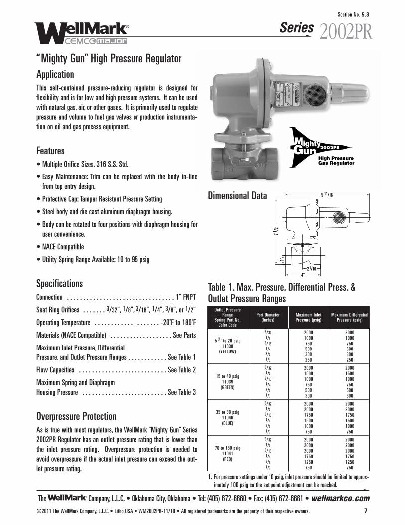
The Company, L.L.C. • Oklahoma City, Oklahoma • Tel: (405) 672-6660 • Fax: (405) 672-6661 • wellmarkco.com
Series
©2011 The WellMark Company, L.L.C. • Litho USA • WM2002PR-11/10 • All registered trademarks are the property of their respective owners. 7
2002PRSection No. 5.3
“Mighty Gun” High Pressure RegulatorApplicationThis self-contained pressure-reducing regulator is designed forflexibility and is for low and high pressure systems. It can be usedwith natural gas, air, or other gases. It is primarily used to regulatepressure and volume to fuel gas valves or production instrumenta-tion on oil and gas process equipment.
Features• Multiple Orifice Sizes, 316 S.S. Std.
• Easy Maintenance: Trim can be replaced with the body in-linefrom top entry design.
• Protective Cap: Tamper Resistant Pressure Setting
• Steel body and die cast aluminum diaphragm housing.
• Body can be rotated to four positions with diaphragm housing foruser convenience.
• NACE Compatible
• Utility Spring Range Available: 10 to 95 psig
SpecificationsConnection . . . . . . . . . . . . . . . . . . . . . . . . . . . . . . . . . 1" FNPT
Seat Ring Orifices . . . . . . . 3/32", 1/8", 3/16", 1/4", 3/8", or 1/2"
Operating Temperature . . . . . . . . . . . . . . . . . . . . -20˚F to 180˚F
Materials (NACE Compatible) . . . . . . . . . . . . . . . . . . . See Parts
Maximum Inlet Pressure, Differential Pressure, and Outlet Pressure Ranges . . . . . . . . . . . . See Table 1
Flow Capacities . . . . . . . . . . . . . . . . . . . . . . . . . . . See Table 2
Maximum Spring and Diaphragm Housing Pressure . . . . . . . . . . . . . . . . . . . . . . . . . . See Table 3
Overpressure ProtectionAs is true with most regulators, the WellMark “Mighty Gun” Series2002PR Regulator has an outlet pressure rating that is lower thanthe inlet pressure rating. Overpressure protection is needed toavoid overpressure if the actual inlet pressure can exceed the out-let pressure rating.
9 11/16
4"2 1/16
1"7 1 /
2
Dimensional Data
1. For pressure settings under 10 psig, inlet pressure should be limited to approx-imately 100 psig so the set point adjustment can be reached.
Outlet PressureRange Port Diameter Maximum Inlet Maximum Differential
Spring Part No. (Inches) Pressure (psig) Pressure (psig)Color Code
3/32 2000 2000
5 (1) to 20 psig1/8 1000 1000
110383/16 750 750
(YELLOW)1/4 500 5003/8 300 3001/2 250 250
3/32 2000 2000
15 to 40 psig1/8 1500 1500
110393/16 1000 1000
(GREEN)1/4 750 7503/8 500 5001/2 300 300
3/32 2000 2000
35 to 80 psig1/8 2000 2000
110403/16 1750 1750
(BLUE)1/4 1500 15003/8 1000 10001/2 750 750
3/32 2000 2000
70 to 150 psig1/8 2000 2000
110413/16 2000 2000
(RED)1/4 1750 17503/8 1250 12501/2 750 750
Table 1. Max. Pressure, Differential Press. &Outlet Pressure Ranges
High PressureGas Regulator
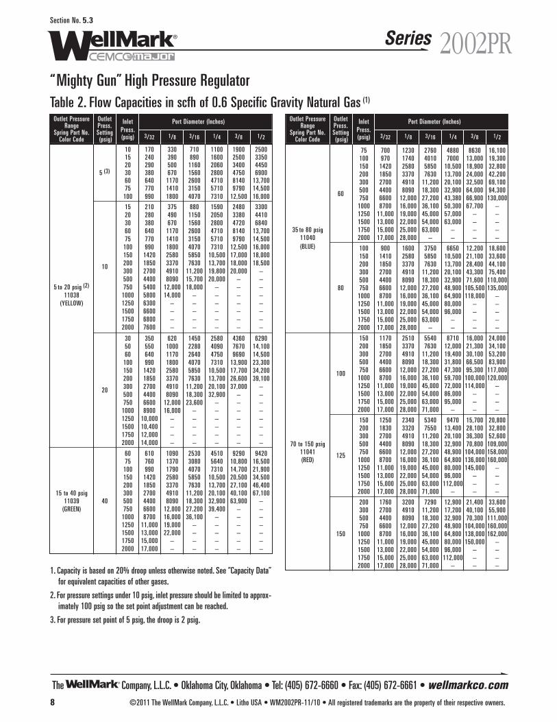
The Company, L.L.C. • Oklahoma City, Oklahoma • Tel: (405) 672-6660 • Fax: (405) 672-6661 • wellmarkco.com
Series
8 ©2011 The WellMark Company, L.L.C. • Litho USA • WM2002PR-11/10 • All registered trademarks are the property of their respective owners.
2002PRSection No. 5.3
“Mighty Gun” High Pressure RegulatorTable 2. Flow Capacities in scfh of 0.6 Specific Gravity Natural Gas (1)
Outlet Pressure Outlet Inlet Port Diameter (Inches)Range Press.
Press.Spring Part No. Setting(psig) 3/32 1/8 3/16 1/4 3/8 1/2Color Code (psig)
10 170 330 710 1100 1900 250015 240 390 890 1600 2500 335020 290 500 1160 2060 3400 4450
5 (3) 30 380 670 1560 2800 4750 690060 640 1170 2600 4710 8140 13,70075 770 1410 3150 5710 9790 14,500
100 990 1800 4070 7310 12,500 16,000
15 210 375 880 1590 2480 330020 280 490 1150 2050 3380 441030 380 670 1560 2800 4720 684060 640 1170 2600 4710 8140 13,70075 770 1410 3150 5710 9790 14,500
100 990 1800 4070 7310 12,500 16,000150 1420 2580 5850 10,500 17,000 18,000
10 200 1850 3370 7630 13,700 18,000 18,500300 2700 4910 11,200 19,800 20,000 –500 4400 8090 15,700 20,000 – –
5 to 20 psig (2) 750 5400 12,000 18,000 – – –11038 1000 5800 14,000 – – – –
(YELLOW) 1250 6300 – – – – –1500 6600 – – – – –1750 6800 – – – – –2000 7600 – – – – –
30 350 620 1450 2580 4360 629050 550 1000 2280 4090 7670 14,10060 640 1170 2640 4750 9690 14,500
100 990 1800 4070 7310 13,900 23,300150 1420 2580 5850 10,500 17,700 34,200200 1850 3370 7630 13,700 26,600 39,100
20 300 2700 4910 11,200 20,100 37,000 –500 4400 8090 18,300 32,900 – –750 6600 12,000 23,600 – – –
1000 8900 16,000 – – – –1250 10,000 – – – – –1500 10,400 – – – – –1750 12,000 – – – – –2000 14,000 – – – – –
60 610 1090 2530 4510 9290 942075 760 1370 3080 5640 10,800 16,500
100 990 1790 4070 7310 14,700 21,900150 1420 2580 5850 10,500 20,500 34,500200 1850 3370 7630 13,700 27,100 46,400
15 to 40 psig 300 2700 4910 11,200 20,100 40,100 67,10011039 40 500 4400 8090 18,300 32,900 63,900 –
(GREEN) 750 6600 12,000 27,200 39,400 – –1000 8700 16,000 36,100 – – –1250 11,000 19,000 – – – –1500 13,000 22,000 – – – –1750 15,000 – – – – –2000 17,000 – – – – –
Outlet Pressure Outlet Inlet Port Diameter (Inches)Range Press.
Press.Spring Part No. Setting(psig) 3/32 1/8 3/16 1/4 3/8 1/2Color Code (psig)
75 700 1230 2760 4880 8630 16,100100 970 1740 4010 7000 13,000 19,300150 1420 2580 5850 10,500 18,900 32,800200 1850 3370 7630 13,700 24,000 42,200300 2700 4910 11,200 20,100 32,500 69,100
60 500 4400 8090 18,300 32,900 64,000 94,300750 6600 12,000 27,200 43,380 66,900 130,000
1000 8700 16,000 36,100 50,300 67,700 –1250 11,000 19,000 45,000 57,000 – –1500 13,000 22,000 54,000 63,000 – –
35 to 80 psig 1750 15,000 25,000 63,000 – – –11040 2000 17,000 28,000 – – – –(BLUE) 100 900 1600 3750 6650 12,200 18,600
150 1410 2580 5850 10,500 21,100 33,600200 1850 3370 7630 13,700 28,400 44,100300 2700 4910 11,200 20,100 43,300 75,400500 4400 8090 18,300 32,900 71,600 110,000
80 750 6600 12,000 27,200 48,900 105,500 135,0001000 8700 16,000 36,100 64,900 118,000 –1250 11,000 19,000 45,000 80,000 – –1500 13,000 22,000 54,000 96,000 – –1750 15,000 25,000 63,000 – – –2000 17,000 28,000 – – – –
150 1170 2510 5540 8710 16,000 24,000200 1850 3370 7630 12,000 21,300 34,100300 2700 4910 11,200 19,400 30,100 53,200500 4400 8090 18,300 31,800 66,500 83,900
100 750 6600 12,000 27,200 47,300 95,300 117,0001000 8700 16,000 36,100 59,700 100,000 120,0001250 11,000 19,000 45,000 72,000 114,000 –1500 13,000 22,000 54,000 86,000 – –1750 15,000 25,000 63,000 95,000 – –2000 17,000 28,000 71,000 – – –
150 1250 2340 5340 9470 15,700 20,800200 1830 3320 7550 13,400 28,100 32,800300 2700 4910 11,200 20,100 36,300 52,600
70 to 150 psig 500 4400 8090 18,300 32,900 70,800 109,00011041 125 750 6600 12,000 27,200 48,900 104,000 158,000(RED) 1000 8700 16,000 36,100 64,800 136,000 160,000
1250 11,000 19,000 45,000 80,000 145,000 –1500 13,000 22,000 54,000 96,000 – –1750 15,000 25,000 63,000 112,000 – –2000 17,000 28,000 71,000 – – –
200 1760 3200 7290 12,900 21,400 33,600300 2700 4910 11,200 17,200 40,100 55,900500 4400 8090 18,300 32,900 70,300 111,000750 6600 12,000 27,200 48,900 104,000 160,000
150 1000 8700 16,000 36,100 64,800 138,000 162,0001250 11,000 19,000 45,000 80,000 150,000 –1500 13,000 22,000 54,000 96,000 – –1750 15,000 25,000 63,000 112,000 – –2000 17,000 28,000 71,000 – – –
1. Capacity is based on 20% droop unless otherwise noted. See “Capacity Data”for equivalent capacities of other gases.
2. For pressure settings under 10 psig, inlet pressure should be limited to approx-imately 100 psig so the set point adjustment can be reached.
3. For pressure set point of 5 psig, the droop is 2 psig.
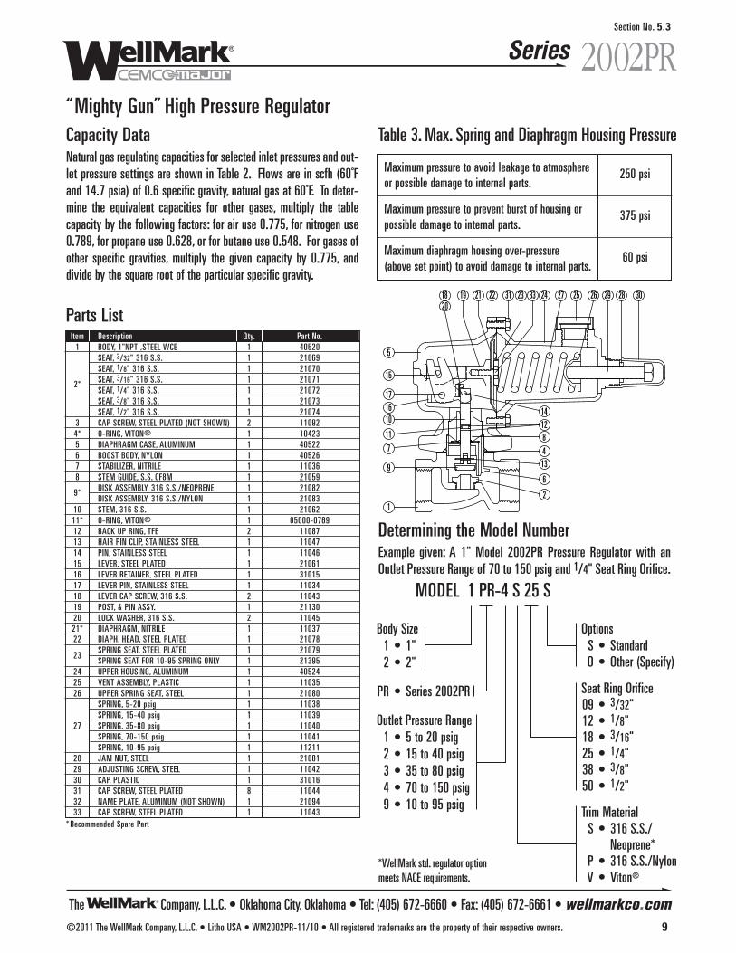
The Company, L.L.C. • Oklahoma City, Oklahoma • Tel: (405) 672-6660 • Fax: (405) 672-6661 • wellmarkco.com
Series
“Mighty Gun” High Pressure Regulator
Determining the Model NumberExample given: A 1" Model 2002PR Pressure Regulator with anOutlet Pressure Range of 70 to 150 psig and 1/4" Seat Ring Orifice.
1
128
413
2
96
5
15
1716
11
7
10
18 19
14
2021 22 31 23 33 24 27 25 26 29 28 30
Parts ListItem Description Qty. Part No.
1 BODY, 1"NPT ,STEEL WCB 1 40520SEAT, 3/32" 316 S.S. 1 21069SEAT, 1/8" 316 S.S. 1 21070
2* SEAT, 3/16" 316 S.S. 1 21071SEAT, 1/4" 316 S.S. 1 21072SEAT, 3/8" 316 S.S. 1 21073SEAT, 1/2" 316 S.S. 1 21074
3 CAP SCREW, STEEL PLATED (NOT SHOWN) 2 110924* O-RING, VITON® 1 104235 DIAPHRAGM CASE, ALUMINUM 1 405226 BOOST BODY, NYLON 1 405267 STABILIZER, NITRILE 1 110368 STEM GUIDE, S.S. CF8M 1 21059
9* DISK ASSEMBLY, 316 S.S./NEOPRENE 1 21082DISK ASSEMBLY, 316 S.S./NYLON 1 21083
10 STEM, 316 S.S. 1 2106211* O-RING, VITON® 1 05000-076912 BACK UP RING, TFE 2 1108713 HAIR PIN CLIP, STAINLESS STEEL 1 1104714 PIN, STAINLESS STEEL 1 1104615 LEVER, STEEL PLATED 1 2106116 LEVER RETAINER, STEEL PLATED 1 3101517 LEVER PIN, STAINLESS STEEL 1 1103418 LEVER CAP SCREW, 316 S.S. 2 1104319 POST, & PIN ASSY. 1 2113020 LOCK WASHER, 316 S.S. 2 1104521* DIAPHRAGM, NITRILE 1 1103722 DIAPH. HEAD, STEEL PLATED 1 21078
23SPRING SEAT, STEEL PLATED 1 21079SPRING SEAT FOR 10-95 SPRING ONLY 1 21395
24 UPPER HOUSING, ALUMINUM 1 4052425 VENT ASSEMBLY, PLASTIC 1 1103526 UPPER SPRING SEAT, STEEL 1 21080
SPRING, 5-20 psig 1 11038SPRING, 15-40 psig 1 11039
27 SPRING, 35-80 psig 1 11040SPRING, 70-150 psig 1 11041SPRING, 10-95 psig 1 11211
28 JAM NUT, STEEL 1 2108129 ADJUSTING SCREW, STEEL 1 1104230 CAP, PLASTIC 1 3101631 CAP SCREW, STEEL PLATED 8 1104432 NAME PLATE, ALUMINUM (NOT SHOWN) 1 2109433 CAP SCREW, STEEL PLATED 1 11043
* Recommended Spare Part
Capacity DataNatural gas regulating capacities for selected inlet pressures and out-let pressure settings are shown in Table 2. Flows are in scfh (60˚Fand 14.7 psia) of 0.6 specific gravity, natural gas at 60˚F. To deter-mine the equivalent capacities for other gases, multiply the tablecapacity by the following factors: for air use 0.775, for nitrogen use0.789, for propane use 0.628, or for butane use 0.548. For gases ofother specific gravities, multiply the given capacity by 0.775, anddivide by the square root of the particular specific gravity.
Table 3. Max. Spring and Diaphragm Housing Pressure
Maximum pressure to avoid leakage to atmosphere 250 psior possible damage to internal parts.
Maximum pressure to prevent burst of housing or 375 psipossible damage to internal parts.
Maximum diaphragm housing over-pressure 60 psi(above set point) to avoid damage to internal parts.
OptionsS • StandardO • Other (Specify)
Seat Ring Orifice09 • 3/32"12 • 1/8"18 • 3/16"25 • 1/4"38 • 3/8"50 • 1/2"
Trim MaterialS • 316 S.S./
Neoprene*P • 316 S.S./NylonV • Viton®
Body Size1 • 1"2 • 2"
PR • Series 2002PR
Outlet Pressure Range1 • 5 to 20 psig2 • 15 to 40 psig3 • 35 to 80 psig4 • 70 to 150 psig9 • 10 to 95 psig
MODEL 1 PR-4 S 25 S
*WellMark std. regulator optionmeets NACE requirements.
2002PR
©2011 The WellMark Company, L.L.C. • Litho USA • WM2002PR-11/10 • All registered trademarks are the property of their respective owners. 9
Section No. 5.3

IN OUT
Mounting HolesFor 5/16 Bolts
1/4"-18 NPTGauge Port
1/4"-18 NPTVent
1/4"-18 NPTInlet & Outlet
2.2501.125
6.875
App
rox.
.625
.625
.695
2.960
3.310
App
rox.
2.86
2.580
1/4"-18 NPTGauge Port
1/4"-18 NPTVent
1/4"-18 NPTInlet & Outlet
IN OUT 4.875
App
rox.
3.310
App
rox.
2.580
.50
2.890
“Mini Gun II” General Purpose InstrumentAnd Gas Pressure Regulator
ApplicationThe “Mini Gun II” Series W67R and W67FR regulators are standardequipment for pneumatic liquid level controls and valve positioners,and provide constant and reliable controlled reduced pressures. Inaddition, they can be used for general-purpose control of gas or airto other pneumatic instruments.
Features• Rugged, Compact & Lightweight Construction
• Cost Effective
• Internal Relief
• Filtered and Non-Filtered Options
• Filtered Unit, Panel Mount Standard
• Filtered Unit, 40 Micron Cellulose
• Spring Case Vent Standard, 1/4" FNPT
• Three Output Ranges (See Table 1)
• Easy In-line Maintenance
• Dual Outlets
SpecificationsBody Material . . . . . . . . . . . . . . . . . . . . . . . . Diecast Aluminum
Port Sizes . . . . . . . . . . . . . . . . . . . . . . . . . . . . . . . . . 1/4" FNPT
Inlet Supply Pressure . . . . . . . . . . . . . . . . . . . . . . 250 psi Max.
Temperature . . . . . . . . . . . . . . . . . . . . . . . . . . . . -20˚F to 180˚F
Four Output Ranges . . . . . . . . . . . . . . . 0-120 psig (See Table 1)
Capacities . . . . . . . . . . . . . . . . . . . . . . . . . . . . . . (See Table 2)
Dimensional Data
Just One ofMany Offered FromAn Arsenal ofGeneral PurposePressure Regulators
Non-Filtered Unit
Filtered Units
Series W67Section No. 5.6
The Company, L.L.C. • Oklahoma City, Oklahoma • Tel: (405) 672-6660 • Fax: (405) 672-6661 • wellmarkco.com©2011 The WellMark Company, L.L.C. • Litho USA • WM67-11/10 • All registered trademarks are the property of their respective owners. 15
Table 1 • Outlet Pressure (psig)Outlet Press. Control Spring Data
Range Part Number Color Code0 to 35 11161 UNPAINTED0 to 60 11163 BLUE
0 to 120 11164 RED
Table 2 • Pressure Range (psig) & Capacity (scfh)Outlet Outlet Press. Inlet Capacity In SCFH of 0.6 Specific Gravity Natural GasPress. Range Press > 50 75 100 150 250
25 0-35 CAPACITY > 516 710 968 1290 180640 0-60 CAPACITY > 194 645 645 903 180680 0-120 CAPACITY > — — 516 839 1290
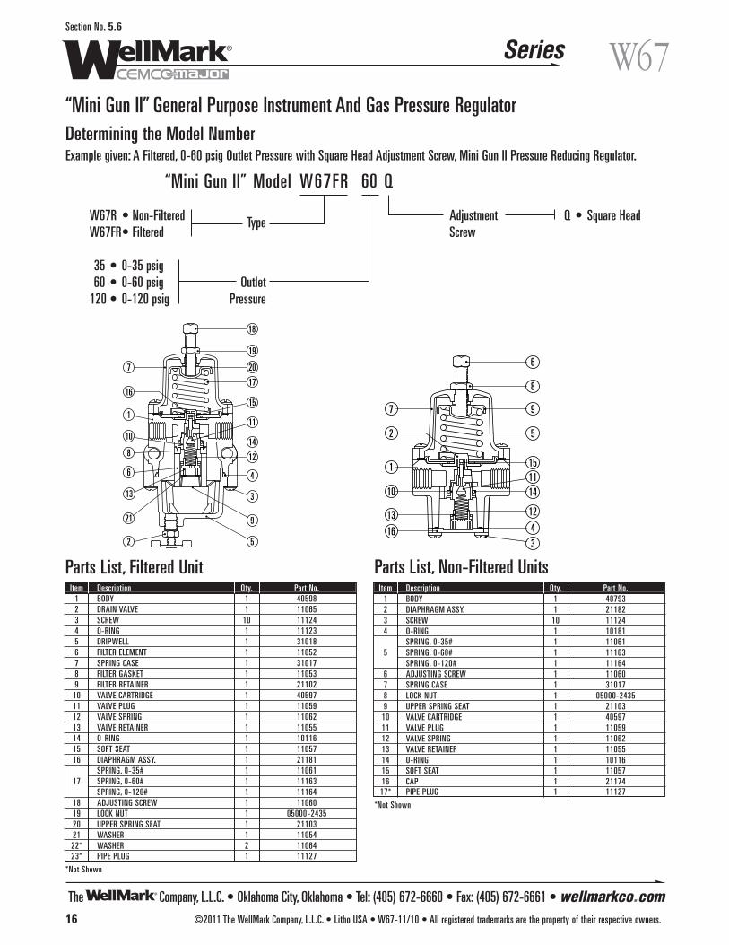
“Mini Gun II” General Purpose Instrument And Gas Pressure RegulatorDetermining the Model NumberExample given: A Filtered, 0-60 psig Outlet Pressure with Square Head Adjustment Screw, Mini Gun II Pressure Reducing Regulator.
Q • Square HeadW67R • Non-FilteredW67FR• Filtered
35 • 0-35 psig60 • 0-60 psig
120 • 0-120 psig
Type
Model W67FR 60 Q“Mini Gun II”
OutletPressure
AdjustmentScrew
Parts List, Non-Filtered Units
The Company, L.L.C. • Oklahoma City, Oklahoma • Tel: (405) 672-6660 • Fax: (405) 672-6661 • wellmarkco.com
Series
16 ©2011 The WellMark Company, L.L.C. • Litho USA • W67-11/10 • All registered trademarks are the property of their respective owners.
W67Section No. 5.6
2 5
9
3
4
12
14
11
15
17
20
19
18
21
13
6
8
10
1
16
7
34
12
141115
5
9
8
6
16
13
10
1
2
7
Parts List, Filtered UnitItem Description Qty. Part No.
1 BODY 1 405982 DRAIN VALVE 1 110653 SCREW 10 111244 O-RING 1 111235 DRIPWELL 1 310186 FILTER ELEMENT 1 110527 SPRING CASE 1 310178 FILTER GASKET 1 110539 FILTER RETAINER 1 21102
10 VALVE CARTRIDGE 1 4059711 VALVE PLUG 1 1105912 VALVE SPRING 1 1106213 VALVE RETAINER 1 1105514 O-RING 1 1011615 SOFT SEAT 1 1105716 DIAPHRAGM ASSY. 1 21181
SPRING, 0-35# 1 1106117 SPRING, 0-60# 1 11163
SPRING, 0-120# 1 1116418 ADJUSTING SCREW 1 1106019 LOCK NUT 1 05000-243520 UPPER SPRING SEAT 1 2110321 WASHER 1 1105422* WASHER 2 1106423* PIPE PLUG 1 11127
*Not Shown
Item Description Qty. Part No.1 BODY 1 407932 DIAPHRAGM ASSY. 1 211823 SCREW 10 111244 O-RING 1 10181
SPRING, 0-35# 1 110615 SPRING, 0-60# 1 11163
SPRING, 0-120# 1 111646 ADJUSTING SCREW 1 110607 SPRING CASE 1 310178 LOCK NUT 1 05000-24359 UPPER SPRING SEAT 1 21103
10 VALVE CARTRIDGE 1 4059711 VALVE PLUG 1 1105912 VALVE SPRING 1 1106213 VALVE RETAINER 1 1105514 O-RING 1 1011615 SOFT SEAT 1 1105716 CAP 1 2117417* PIPE PLUG 1 11127
*Not Shown
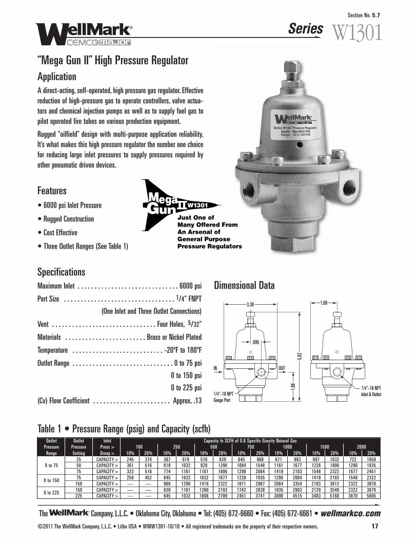
“Mega Gun II” High Pressure RegulatorApplicationA direct-acting, self-operated, high pressure gas regulator. Effectivereduction of high-pressure gas to operate controllers, valve actua-tors and chemical injection pumps as well as to supply fuel gas topilot operated fire tubes on various production equipment.
Rugged “oilfield” design with multi-purpose application reliability.It’s what makes this high pressure regulator the number one choicefor reducing large inlet pressures to supply pressures required byother pneumatic driven devices.
Features• 6000 psi Inlet Pressure
• Rugged Construction
• Cost Effective
• Three Outlet Ranges (See Table 1)
SpecificationsMaximum Inlet . . . . . . . . . . . . . . . . . . . . . . . . . . . . . . 6000 psi
Port Size . . . . . . . . . . . . . . . . . . . . . . . . . . . . . . . . . 1/4" FNPT
(One Inlet and Three Outlet Connections)
Vent . . . . . . . . . . . . . . . . . . . . . . . . . . . . . . . Four Holes, 5/32"
Materials . . . . . . . . . . . . . . . . . . . . . . . . Brass or Nickel Plated
Temperature . . . . . . . . . . . . . . . . . . . . . . . . . . . -20ºF to 180ºF
Outlet Range . . . . . . . . . . . . . . . . . . . . . . . . . . . . . . 0 to 75 psi
0 to 150 psi
0 to 225 psi
(Cv) Flow Coefficient . . . . . . . . . . . . . . . . . . . . . . . Approx. .13
Dimensional Data
Just One ofMany Offered FromAn Arsenal ofGeneral PurposePressure Regulators
Series W1301Section No. 5.7
The Company, L.L.C. • Oklahoma City, Oklahoma • Tel: (405) 672-6660 • Fax: (405) 672-6661 • wellmarkco.com©2011 The WellMark Company, L.L.C. • Litho USA • WMW1301-10/10 • All registered trademarks are the property of their respective owners. 17
3.38
.695
1/4"-18 NPTGauge Port
5.62
1.88
IN OUT
1.69
1/4"-18 NPTInlet & Outlet
Table 1 • Pressure Range (psig) and Capacity (scfh)Outlet Outlet Inlet Capacity In SCFH of 0.6 Specific Gravity Natural Gas
Pressure Pressure Press > 100 250 500 750 1000 1500 2000Range Setting Droop > 10% 20% 10% 20% 10% 20% 10% 20% 10% 20% 10% 20% 10% 20%
25 CAPACITY > 245 374 387 619 516 839 645 968 671 993 697 1032 722 10580 to 75 50 CAPACITY > 361 516 619 1032 929 1290 1084 1548 1161 1677 1226 1806 1290 1935
75 CAPACITY > 323 516 774 1161 1161 1806 1290 2064 1419 2193 1548 2322 1677 2451
0 to 150 75 CAPACITY > 258 452 645 1032 1032 1677 1226 1935 1290 2064 1419 2193 1548 2322150 CAPACITY > — — 968 1290 1419 2322 1871 2967 2064 3354 2193 3612 2322 3870
0 to 225 150 CAPACITY > — — 839 1161 1290 2193 1742 2838 1935 2903 2129 3548 2322 3870225 CAPACITY > — — 645 1032 1806 2709 2451 3741 3096 4515 3483 5160 3870 5805

The Company, L.L.C. • Oklahoma City, Oklahoma • Tel: (405) 672-6660 • Fax: (405) 672-6661 • wellmarkco.com
Series
18 ©2011 The WellMark Company, L.L.C. • Litho USA • WMW1301-10/10 • All registered trademarks are the property of their respective owners.
W1301Section No. 5.7
“Mega Gun II” High Pressure Regulator
Determining the Model NumberExample given: Standard Model 150-QBR, Series W1301 Regulator, 0-150 psi Outlet Pressure Range, Square Head Adjustment andBrass Body.
BR • Brass NI • Ni-Plated
Q • Square Head T • T-Bar
075 • 0-75 psi150 • 0-150 psi225 • 0-225 psi
Outlet Pressure
Model 150 - Q BR“Mega Gun II”
AdjustmentScrew
BodyMaterial
15
18
9
2
8
21
17
4
14
11
19
10
3
12
716
13
1
5
6
20
Parts ListItem Description Qty. Part No.
1 BODY 1 407762 SPRING CASE 1 407783 BOTTOM CAP 1 310354 YOKE, BOTTOM 1 211525 SEAT RING 1 211546 VALVE DISK ASSEMBLY 1 211567 DIAPHRAGM 2 211558 DIAPHRAGM HEAD 1 211609 UPPER SPRING SEAT 1 21161
10 VALVE SPRING 1 11109SPRING, 0-75# 1 11110
11 SPRING, 0-150# 1 11115SPRING, 0-225# 1 11116
12 BODY GASKET 1 1110813 DIAPHRAGM HEAD GASKET 1 1110714 O-RING 1 1064515 ADJUSTING SCREW 1 1111116 SOCKET HEAD SCREW 6 1111317 FLAT HEAD SCREW 2 1111718 JAM NUT 1 1111219 HEX NUT 1 1111420 VALVE DISK COLLAR 1 2115921 YOKE, TOP 1 21153
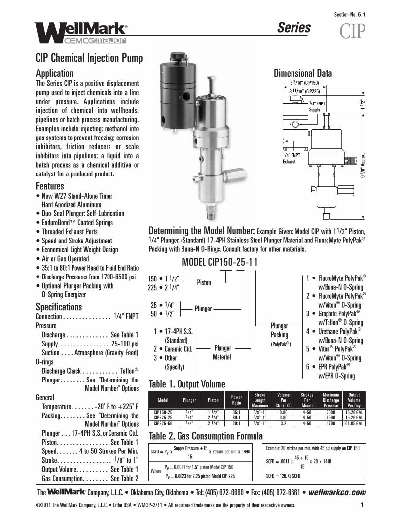
The Company, L.L.C. • Oklahoma City, Oklahoma • Tel: (405) 672-6660 • Fax: (405) 672-6661 • wellmarkco.com
Series
©2011 The WellMark Company, L.L.C. • Litho USA • WMCIP-2/11 • All registered trademarks are the property of their respective owners. 1
CIPSection No. 6.1
CIP Chemical Injection PumpApplicationThe Series CIP is a positive displacementpump used to inject chemicals into a lineunder pressure. Applications includeinjection of chemical into wellheads,pipelines or batch process manufacturing.Examples include injecting: methanol intogas systems to prevent freezing; corrosioninhibitors, friction reducers or scaleinhibitors into pipelines; a liquid into abatch process as a chemical additive orcatalyst for a produced product.
Features• New W27 Stand-Alone Timer
Hard Anodized Aluminum• Duo-Seal Plunger: Self-Lubrication• EnduroBond™ Coated Springs• Threaded Exhaust Ports• Speed and Stroke Adjustment• Economical Light Weight Design• Air or Gas Operated• 35:1 to 80:1 Power Head to Fluid End Ratio• Discharge Pressures from 1700-6500 psi• Optional Plunger Packing with
O-Spring Energizer
SpecificationsConnection . . . . . . . . . . . . . . . 1/4" FNPTPressure
Discharge . . . . . . . . . . . . . See Table 1Supply . . . . . . . . . . . . . . . 25-100 psiSuction . . . . Atmosphere (Gravity Feed)
O-ringsDischarge Check . . . . . . . . . . . Teflon®
Plunger . . . . . . . . See “Determining theModel Number” Options
GeneralTemperature . . . . . . . -20˚ F to +225˚ FPacking. . . . . . . . See “Determining the
Model Number” OptionsPlunger . . . 17-4PH S.S. or Ceramic Ctd.Piston. . . . . . . . . . . . . . . . See Table 1Speed. . . . . . . 4 to 50 Strokes Per Min.Stroke. . . . . . . . . . . . . . . . . 1/8" to 1"Output Volume. . . . . . . . . . See Table 1Gas Consumption. . . . . . . . See Table 2
9 3 /
8" A
ppro
x.
S
1/4" FNPTSupply
1/4" FNPTExhaust
3 3/16" (CIP150)
3 11/16" (CIP225)
1 1 /
2"
Power Stroke Volume Strokes Maximum OutputModel Plunger Piston Length Per Per Discharge VolumeRatio Maximum Stroke CC Minute Pressure Per Day
CIP150-25 1/4" 1 1/2" 35:1 1/8"-1" 0.80 4-50 3000 15.26 GALCIP225-25 1/4" 2 1/4" 80:1 1/8"-1" 0.80 4-50 6500 15.26 GALCIP225-50 1/2" 2 1/4" 20:1 1/8"-1" 3.2 4-50 1700 61.05 GAL
Table 2. Gas Consumption Formula
Table 1. Output Volume
SCFD = Pv xSupply Pressure +15
x strokes per min x 144015
WherePv = 0.0011 for 1.5" piston Model CIP 150
Pv = 0.0023 for 2.25 piston Model CIP 225
Example: 20 strokes per min. with 45 psi supply on CIP 150
SCFD = .0011 x45 + 15
x 20 x 144015
SCFD = 126.72 SCFD
Determining the Model Number: Example Given: Model CIP with 11/2" Piston, 1/4" Plunger, (Standard) 17-4PH Stainless Steel Plunger Material and FluoroMyte PolyPak®
Packing with Buna-N O-Rings. Consult factory for other materials.
1 • FluoroMyte PolyPak®
w/Buna-N O-Spring2 • FluoroMyte PolyPak®
w/Viton® O-Spring3 • Graphite PolyPak®
w/Teflon® O-Spring4 • Urethane PolyPak®
w/Buna-N O-Spring5 • Viton® PolyPak®
w/Viton® O-Spring6 • EPR PolyPak®
w/EPR O-Spring
150 • 1 1/2"225 • 2 1/4"
25 • 1/4"50 • 1/2"
1 • 17-4PH S.S.(Standard)
2 • Ceramic Ctd.3 • Other
(Specify)
MODEL CIP150-25-1 1
Piston
PlungerPacking(PolyPak® )
PlungerMaterial
Plunger
Dimensional Data

The Company, L.L.C. • Oklahoma City, Oklahoma • Tel: (405) 672-6660 • Fax: (405) 672-6661 • wellmarkco.com
Series
2 ©2011 The WellMark Company, L.L.C. • Litho USA • WMCIP-2/11 • All registered trademarks are the property of their respective owners.
CIPSection No. 6.1
CIP Chemical Injection PumpCIP Injection Pump Parts List
1
2
3
6
4
7
5
24
14
23
22
17
18
9
10
19
21
20
18
16
12
11
13
15
8
Item Description Qty. Part No.CIP150-25 CIP225-25 CIP225-50
1 STROKE ADJUSTER 1 05000-5660 05000-5694 05000-56942 LOCK NUT 1 05000-2559 05000-1957 05000-19573 THREAD SEAL 1 06000-8527 06000-8528 06000-85294* O-RING 1 05000-0033 05000-0066 05000-00665 PISTON CAP 1 05013-1540 05013-1733 05013-17336 DATA PLATE 1 06000-8050 06000-8084 06000-80847* U CUP-PISTON 1 06000-7951 06000-8076 06000-8076
8* PLUNGER/PISTON ASSY., 17-4PH S.S. (STD.) 1 06500-7029 06500-7025 06500-7021PLUNGER/PISTON ASSY., CERAMIC CTD. 1 06500-7027 06500-7023 06500-7022
9 PIPE NIPPLE 1 006312-P 006312-P 006312-P10* TIMER ASSEMBLY, W27 1 06500-7400 06500-7400 06500-740011 WASHER 1 05010-4116 05010-4116 06000-814112* POLYPAK® 1 06000-7976 06000-7976 06000-813313 LOCK WASHER 6 05000-5677 05000-5677 05000-567714 SOCKET HEAD SCREW 6 05000-5644 05000-5644 05000-564415* SPRING, ENDUROBOND™ COATED 1 06000-8069 06000-8069 06000-806916 PIPE PLUG 2 002303-P 002303-P 002303-P17 BODY/FLUID END ASSY. 1 06500-5834 06500-5915 06500-599918* SPACER 2 05013-1765 05013-1765 05013-1926
FLUOROMYTE/BUNA-N (1) 1 06000-8158 06000-8158 06000-8644FLUOROMYTE/VITON® (2) 1 06000-7969 06000-7969 06000-8125
19* PACKING GRAPHITE/TEFLON® (3) 1 06000-8997 06000-8997 06000-9032POLYPAK® URETHANE/BUNA-N (4) 1 06000-7976 06000-7976 06000-8133
VITON®/VITON® (5) 1 06000-9082 06000-9082 06000-9169EPR POLYPAK® (6) 1 10341 10341 06000-9235
20 BLEED SCREW 1 05013-1558 05013-1558 05013-1558
21*O-RING, BUNA-N 1 05000-0082 05000-0082 05000-0108O-RING, VITON® 1 05000-5610 05000-5610 05000-0835
22* SUCTION CHECK VALVE 1 06500-5907 06500-5907 06500-601822A CHECK VALVE BODY 1 05013-1566 05013-1566 05013-193422B BALL RETAINER 1 05013-1574 05013-1574 05013-194222C BALL 1 06000-0265 06000-0265 06000-027523* DISCHARGE CHECK VALVE 1 06500-5890 06500-5890 06500-589023A CHECK VALVE BODY 1 05013-1682 05013-1682 05013-168223B O-RING RETAINER 1 05013-1690 05013-1690 05013-169023C O-RING, TEFLON® 1 10867 10867 1086723D BALL 1 06000-0265 06000-0265 06000-026523E SPRING 1 A18-1Y A18-1Y A18-1Y23F SPRING RETAINER NUT 1 05013-1708 05013-1708 05013-170824 MUFFLER 1 06000-8166 06000-8166 06000-8166
*Recommended Spare Part
Complete Standard Repair Kit(17-4PH Plunger)
1/8" FNPTTo Pump
1/4" FNPTExhaust
1/4" FNPTSupply
17
23
2
19
9
12
5
4
13
16
15
26
24
22
21
1820
63
10
11
1
7
8
14
25
W27 Timer Assembly Parts List (Item No. 10 from above)Item Description Qty. Part No.
1 BODY 1 05013-35322 CAP 1 05013-34553 SPOOL, UPPER 1 05013-34634 SPOOL, LOWER 1 05013-34735 SPACER 1 05013-34806 DIAPHRAGM PLATE 1 05013-34987 SEAT, UPPER 1 05013-35078 SEAT, LOWER 1 05013-35149* DIAPHRAGM, UPPER 1 05013-354810* DIAPHRAGM,SNAPPER 1 05013-355611* DIAPHRAGM, LOWER 1 05013-356612 SOCKET HD. SCREW 1 05000-591013 SPRING, UPPER 1 06000-8892
*Recommended Spare Part
Model Part No.CIP150-25 03500-1922CIP225-25 03500-1930CIP225-50 03500-1948
Repair Kit (Major): Item 3, 4, 7, 8,10,12,15,18,19, 21,22, 23
W27 Timer Repair KitsType Part No.
MINOR REPAIR KIT 03500-7401Repair Kit (Minor): Item 9, 10, 11, 16, 18, 19
Type Part No.MAJOR REPAIR KIT 03500-7402
Repair Kit (Major): Item 7, 8, 9,10,11,13,14,15,16,18, 19
Standard Repair Kit Without Timer, Suction & Discharge Valve
Model Part No.CIP150-25 03500-1956CIP225-25 03500-1964CIP225-50 03500-1972
Repair Kit (Minor): Item 3, 4, 7, 8, 12, 15, 18, 19, 21
Item Description Qty. Part No.14 SPRING, LOWER 1 06000-887615 PILOT PLUG 1 06500-646816* O-RING 1 05000-006617 ADJUSTING NEEDLE 1 05013-283718* O-RING 1 05000-000919* O-RING, TEFLON® 1 05000-582820 SEAT 1 05013-383521 LEGEND PLATE 1 06000-856022 SPRING 1 06000-861023 PIN 1 05013-291124 KNOB 1 1089825 SOCKET HD. SCREW 4 05000-590226 WASHER 4 05000-5836
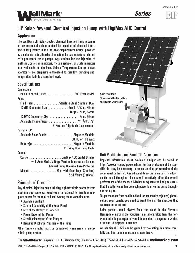
The Company, L.L.C. • Oklahoma City, Oklahoma • Tel: (405) 672-6660 • Fax: (405) 672-6661 • wellmarkco.com
Series
©2012 The WellMark Company, L.L.C. • Litho USA • WMCIP-SOLAR-2/11 • All registered trademarks are the property of their respective owners. 3
EIPSection No. 6.2
EIP Solar-Powered Chemical Injection Pump with DigiMax ADC ControlApplicationThe WellMark EIP Solar-Electric Chemical Injection Pump providesan environmentally-clean method for injection of chemical into aline under pressure. It is a positive-displacement design, poweredby an electric motor, thereby eliminating the gas emissions inherentwith pneumatic-style pumps. Applications include injection ofmethanol, corrosion inhibitors, friction reducers or scale inhibitorsinto wellheads or pipelines. Unique Temperature Sensor allowsoperator to set temperature threshold to disallow pumping untiltemperature falls to a specified level.
SpecificationsConnectionsPump Inlet and Outlet . . . . . . . . . . . . . . . . . 1/4" Female NPT
PumpFluid Head . . . . . . . . . . . . . . . . Stainless Steel, Single or Dual12VDC Gearmotor Size . . . . . . . . . . . . . Small - 1/17hp, 30rpm
Large -1/6hp, 64rpm120VAC Gearmotor Size . . . . . . . . . . . . . . . . . . 1/6hp, 60rpmAvailable Plunger Sizes . . . . . . . . . . . . . . . . . 1/4", 3/8", 1/2"
3-Position Adjustable DisplacementPower • DCAvailable Solar Panels . . . . . . . . . . . . . . . . Single or Multiple
50, 80 or 110 WattBattery(s) . . . . . . . . . . . . . . . . . . . . . . . . . Single or Multiple
110 Amp Hour Deep CycleGeneralControl . . . . . . . . . . . . . . . . . . . . DigiMax ADC Digital Display
with Auto Mode, Voltage Monitor, Temperature Sensor,Manual Pump Override, Fuse Protected
Mounts . . . . . . . . . . . . . . . . Mast with Quad Legs (Standard)Skid Mount (Optional)
Principle of OperationAny chemical injection pump utilizing a photovoltaic power systemmust manage numerous variables in an attempt to maintain ade-quate power for the task at hand. Among those variables are:• Available Sunlight• Size and Capability of the Solar Panel• Size of the Battery or Batteries• Power Draw of the Motor• Size/Displacement of the Plunger• Required Discharge Pressure of the Pump
All of these variables must be considered when sizing a photo-voltaic pump system.
Unit Positioning and Panel Tilt AdjustmentRegional information about available sunlight can be found athttp://www.nrel.gov/gis/solar.html. Further evaluation of the spe-cific site may be necessary to maximize clear presentation of thesolar panel to the sun. Any adjacent items that may casts shadowson the panel throughout the day will negatively affect the overallperformance of the package. Maximum exposure will help to assurethat the battery maintains enough power to drive the pump through-out the night.To get the most from position-fixed (or seasonally adjusted) photo-voltaic solar panels, you need to point them in the direction thatcaptures the most sun.Solar panels should always face true south in the NorthernHemisphere, north in the Southern Hemisphere, tilted from the hor-izontal at a degree equal to your latitude plus 15 degrees in winter,or minus 15 degrees in summer.An additional 3- 5% can be gained by evaluating this more care-fully and fine-tuning adjustments accordingly.
Skid MountedShown with Double Batteryand Double Solar Panel

The Company, L.L.C. • Oklahoma City, Oklahoma • Tel: (405) 672-6660 • Fax: (405) 672-6661 • wellmarkco.com
Series
4 ©2012 The WellMark Company, L.L.C. • Litho USA • WMCIP-SOLAR-2/11 • All registered trademarks are the property of their respective owners.
EIPSection No. 6.2
EIP Solar-Powered Chemical Injection Pump with DigiMax ADC Control
Temperature SensorThe Control Timer is equipped with a Temperature Sensor feature.When activated this feature turns the pump off until the temperaturedrops to a set temperature threshold or lower, regardless of programsettings. This allows the user to minimize the waste of methanol byonly pumping during conditions approaching freezing temperatures.
settings. Control of fluid volume can be achieved by utilizing aninfinite number of combinations of RUN and OFF times along withthree different displacement settings. Suggested settings for commonvolumes are listed on included charts.
Program FunctionsAuto ModeAfter a one-time setup, this feature allows the operator to simplyenter the number of quarts desired per day - No need to consult RUNTIME and OFF TIME charts. The DigiMax ADC is programmed to behassle-free. Of course, Manual Mode is available allowing the userto manually set the control if desired.In Auto Mode Digital Display continuously indicates settings:• Plunger Size and Pin Setting• Battery Voltage• Temp. Settings (ON/OFF, Temp. Threshold Setting and Current)• Pump Rate (Quarts per Day)
In Manual Mode Digital Display continuously indicates settings:• RUN Time• OFF Time• Cycle Count• Battery Voltage• Temp. Settings (ON/OFF, Temp. Threshold Setting and Current)
Pump OverrideRuns pump continuously, overriding the program until the button ispressed again or until the pump runs for 5 minutes.
Pump SelectionA wide ratio between OFF time and RUN time (OFF:RUN) will usual-ly result in maximized efficiency of the battery/solar charging system.For example: 30 seconds OFF time versus 5 seconds RUN timewould result in a ratio of 6:1. Ratios lower than 2:1 may result inprogressive loss of battery charge, depending upon available sun-light and differential pumping pressure.As reviewed against the “Pump Displacement & Timer Settings”charts, (refer to Installation, Operation & Maintenance Instructionsfor Solar-Powered Chemical Injection Pump) the pump's requiredrate should optimally fall within the middle of the pumps capacityrange. This gives room for adjustment if the service criteria changes.
OperationThe WellMark Solar Electric Chemical Injection Pump features acontrol timer that allows a broad range of operating conditions.The pump head can be adjusted for one of three different displacement
Pin position (1, 2 or 3) determines displacement (see charts).Factory preset is Position 3.
123 321
123 321
Displacement Volumes by Pin Placement
DigiMax ADC Control/Timer
NOYES SCROLLMENU
EX
PUMP OVERRIDE
Press Buttons on Ends to ProgramPress ALL 4 BUTTONS to Reset
wellmarkco.com • 405.672.6660
DigiMax ADCAccurate Digital Control
+ -
Plunger/Pin PositionDisplacement Volumes 1/4" Plunger 3/8" Plunger 1/2" Plunger
1 2 3 1 2 3 1 2 3DISPLACEMENT PER STROKE (OZ.) 0.0170 0.0238 0.0306 0.0382 0.0535 0.0688 0.0679 0.0951 0.1223
DISPLACEMENT PER SECOND (SMALL MOTOR) 0.0085 0.0119 0.0153 0.0191 0.0267 0.0344 0.0339 0.0475 0.0611DISPLACEMENT PER SECOND (LARGE MOTOR) 0.0181 0.0254 0.0326 0.0407 0.0570 0.0733 0.0724 0.1014 0.1304
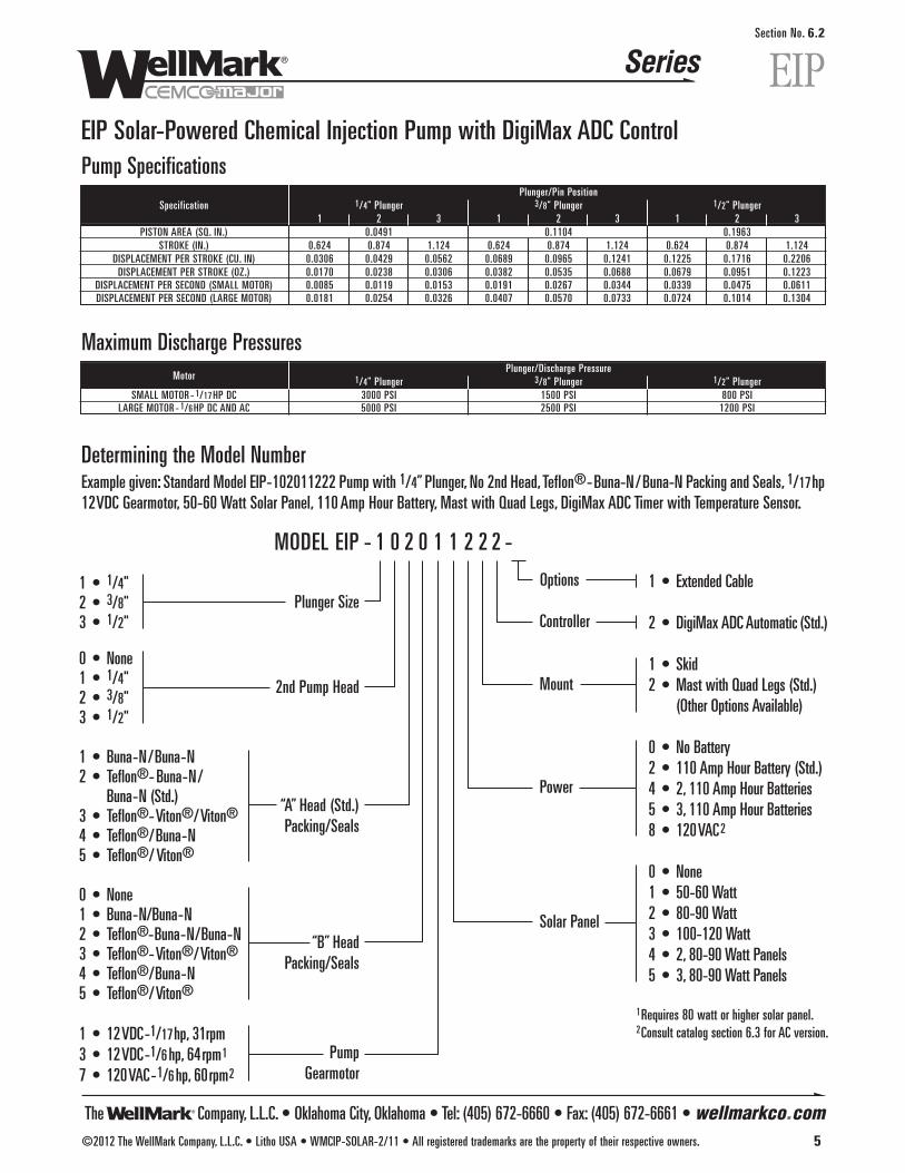
The Company, L.L.C. • Oklahoma City, Oklahoma • Tel: (405) 672-6660 • Fax: (405) 672-6661 • wellmarkco.com
Series
©2012 The WellMark Company, L.L.C. • Litho USA • WMCIP-SOLAR-2/11 • All registered trademarks are the property of their respective owners. 5
EIPSection No. 6.2
EIP Solar-Powered Chemical Injection Pump with DigiMax ADC ControlPump Specifications
Plunger/Pin PositionSpecification 1/4" Plunger 3/8" Plunger 1/2" Plunger
1 2 3 1 2 3 1 2 3PISTON AREA (SQ. IN.) 0.0491 0.1104 0.1963
STROKE (IN.) 0.624 0.874 1.124 0.624 0.874 1.124 0.624 0.874 1.124DISPLACEMENT PER STROKE (CU. IN) 0.0306 0.0429 0.0562 0.0689 0.0965 0.1241 0.1225 0.1716 0.2206DISPLACEMENT PER STROKE (OZ.) 0.0170 0.0238 0.0306 0.0382 0.0535 0.0688 0.0679 0.0951 0.1223
DISPLACEMENT PER SECOND (SMALL MOTOR) 0.0085 0.0119 0.0153 0.0191 0.0267 0.0344 0.0339 0.0475 0.0611DISPLACEMENT PER SECOND (LARGE MOTOR) 0.0181 0.0254 0.0326 0.0407 0.0570 0.0733 0.0724 0.1014 0.1304
Maximum Discharge PressuresMotor
Plunger/Discharge Pressure1/4" Plunger 3/8" Plunger 1/2" Plunger
SMALL MOTOR - 1/17HP DC 3000 PSI 1500 PSI 800 PSILARGE MOTOR - 1/6HP DC AND AC 5000 PSI 2500 PSI 1200 PSI
“A” Head (Std.)Packing/Seals
“B” HeadPacking/Seals
Pump Gearmotor
1 • 1/4"2 • 3/8"3 • 1/2"
0 • None1 • 1/4"2 • 3/8"3 • 1/2"
1 • Buna-N/Buna-N2 • Teflon®-Buna-N/
Buna-N (Std.)3 • Teflon®-Viton®/Viton®4 • Teflon®/Buna-N5 • Teflon®/Viton®
0 • None1 • Buna-N/Buna-N2 • Teflon®-Buna-N/Buna-N3 • Teflon®-Viton®/Viton®4 • Teflon®/Buna-N5 • Teflon®/Viton®
1 • 12VDC-1/17hp, 31rpm3 • 12VDC-1/6hp, 64rpm1
7 • 120VAC-1/6hp, 60rpm2
1 • Extended Cable
2 • DigiMax ADC Automatic (Std.)
1 • Skid2 • Mast with Quad Legs (Std.)
(Other Options Available)
0 • No Battery2 • 110 Amp Hour Battery (Std.)4 • 2, 110 Amp Hour Batteries5 • 3, 110 Amp Hour Batteries8 • 120VAC2
0 • None1 • 50-60 Watt2 • 80-90 Watt3 • 100-120 Watt4 • 2, 80-90 Watt Panels5 • 3, 80-90 Watt Panels
1Requires 80 watt or higher solar panel.2Consult catalog section 6.3 for AC version.
MODEL EIP - 1 0 2 0 1 1 2 2 2 -
2nd Pump Head
Plunger SizeOptions
Controller
Mount
Power
Solar Panel
Determining the Model NumberExample given: Standard Model EIP-102011222 Pump with 1/4” Plunger, No 2nd Head, Teflon®-Buna-N/Buna-N Packing and Seals, 1/17hp12VDC Gearmotor, 50-60 Watt Solar Panel, 110Amp Hour Battery, Mast with Quad Legs, DigiMax ADC Timer with Temperature Sensor.

The Company, L.L.C. • Oklahoma City, Oklahoma • Tel: (405) 672-6660 • Fax: (405) 672-6661 • wellmarkco.com
Series
6 ©2012 The WellMark Company, L.L.C. • Litho USA • WMCIP-SOLAR-2/11 • All registered trademarks are the property of their respective owners.
EIPSection No. 6.2
EIP Solar-Powered Chemical Injection Pump with DigiMax ADC ControlSolar-Powered Pump Unit Component Parts
1/6 hpDC Gearmotor
Cover and Hardware
1/17hpDC Gearmotor
Cover and Hardware
34
33
35
4
4
36
15
31
32
337
1410
1112
131
19
3533
34
1211
1041
1817
16
26
25
39
24
23
22
21
20
28
24
23
25
27
3029
98
540
638
372
3

The Company, L.L.C. • Oklahoma City, Oklahoma • Tel: (405) 672-6660 • Fax: (405) 672-6661 • wellmarkco.com
Series
©2012 The WellMark Company, L.L.C. • Litho USA • WMCIP-SOLAR-2/11 • All registered trademarks are the property of their respective owners. 7
EIPSection No. 6.2
EIP Solar-Powered Chemical Injection Pump with DigiMax ADC ControlSolar-Powered Pump Parts ListItem Description Qty. Part No.
1 HOUSING1/17HP SMALL MOTOR 1 06500-72151/6 HP LARGE MOTOR 1 06500-7219
2 SCREW 2 05000-16923 HEX NUT 2 10007
4 MOTOR1/17HP (SMALL) 1 06000-84871/6HP (LARGE) 1 06000-8485
5 ECCENTRIC WHEEL1/17HP SMALL MOTOR 1 06500-72051/6 HP LARGE MOTOR 1 06500-7209
6 SET SCREW 2 05000-2294
7 LOCK WASHER1/17HP SMALL MOTOR 4 107091/6 HP LARGE MOTOR 7 10709
8 BEARING 1 06000-84779 RECIPROCATING BLOCK 1 05013-699510 BUSHING 2 05013-701211 O-RING 2 1101712 GUIDE NUT 2 05013-702013 GUIDE 1 05013-698614 JAM NUT 1 05013-696815 CAP 1 05013-7119
1/4" 1 05013-690716 FLUID END 3/8" 1 05013-6909
1/2" 1 05013-69051/4" 1 06000-9293
17 PACKING SET-TEFLON®/BUNA-N* 3/8" 1 06000-93011/2" 1 06000-93191/4" 1 05013-7005
18 GLAND NUT 3/8" 1 05013-70011/2" 1 05013-70071/4" 1 05013-6975
19 PLUNGER 3/8" 1 05013-69771/2" 1 05013-6979
20 BALL -1/4" 1 06000-026521 O-RING 1 1046022 SEAT 1 05013-695023 O-RING 2 05000-0066
*Other packing materials available. Consult factory for information.
Panel, Control Box & Stand Parts ListItem Description Qty. Part No.
50 WATT 1 06500-72851 SOLAR PANEL ASSEMBLY 80 WATT 1 06500-7281
110 WATT 1 06500-72832 POST 1 05013-7180
3 QUAD-LEG ASSEMBLY 1 06500-7342SKID ASSEMBLY (NOT SHOWN) 1 06500-7227
4 BATTERY BOX 1 05013-72555 BATTERY 1 06000-84296 CONTROL MOUNTING PLATE 1 05013-72697a DIGIMAX ADC CONTROL 1 06000-63857b TIMER (DISCONTINUED) 1 06000-8435
FOR 50 WATT PANEL 1 06000-84258 CHARGER FOR 80 WATT PANEL 1 06000-8427
FOR 110 WATT PANEL 1 CONSULT FACTORY9 SCREW 8 05000-158510 NY-LOC NUT 8 05000-256711 SCREW 4 05000-184112 LOCK WASHER 4 1101813 NUT 4 05000-210414 LOCK SCREW (NOT SHOWN) 1 05000-200515 STAKE (NOT SHOWN) 4 06500-7418
Note: Wiring harnesses are included with Solar Panel Assemblies and Pump Assemblies. They may however be ordered separately. Consult factory for part numbers, prices and availability.AC Power Versions, Consult Catalog Section 6.3.
Item Description Qty. Part No.24 BALL - 3/8" 2 06000-026725 O-RING 2 05000-005826 DISCHARGE VALVE BODY 1 05013-694227 SUCTION VALVE BODY 1 05013-693428 BLEED SCREW 1 05013-155829 PIN 2 001000-P30 HOUSING COVER 1 05013-713631 WING NUT 2 05000-564232 PUMP BASE 1 05013-7142
33 SCREW, 1/17HP SMALL MOTOR 6 05000-5648SOCKET HEAD 1/6 HP LARGE MOTOR 8 05000-5648
34 MOTOR COVER1/17HP SMALL MOTOR 1 05013-71921/6 HP LARGE MOTOR 1 05013-7190
35 FLAT WASHER1/17HP SMALL MOTOR 2 007124-P1/6 HP LARGE MOTOR 4 007124-P
36 FLAT WASHER 1/17HP SMALL MOTOR 4 05000-614837 LOCK WASHER 1/17HP SMALL MOTOR 4 05000-5836
38 SCREW1/17HP SMALL MOTOR 4 05000-15851/6 HP LARGE MOTOR 3 05000-5646
39 SPRING 1 10606
40 SPACER1/17HP SMALL MOTOR 1 05013-75351/6 HP LARGE MOTOR 1 05013-7543
41 PACKING COVER 1 05013-7527
Digi ADC
Max
1
7a
7b (discontinued)
6
4
111213
59
8
2
10
3

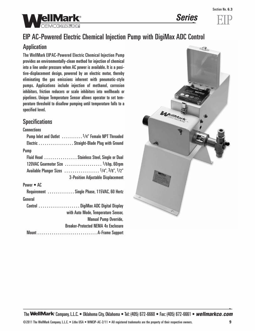
The Company, L.L.C. • Oklahoma City, Oklahoma • Tel: (405) 672-6660 • Fax: (405) 672-6661 • wellmarkco.com
Series
©2011 The WellMark Company, L.L.C. • Litho USA • WMCIP-AC-2/11 • All registered trademarks are the property of their respective owners. 9
EIPSection No. 6.3
EIP AC-Powered Electric Chemical Injection Pump with DigiMax ADC ControlApplicationThe WellMark EIP AC-Powered Electric Chemical Injection Pumpprovides an environmentally-clean method for injection of chemicalinto a line under pressure when AC power is available. It is a posi-tive-displacement design, powered by an electric motor, therebyeliminating the gas emissions inherent with pneumatic-stylepumps. Applications include injection of methanol, corrosioninhibitors, friction reducers or scale inhibitors into wellheads orpipelines. Unique Temperature Sensor allows operator to set tem-perature threshold to disallow pumping until temperature falls to aspecified level.
SpecificationsConnections
Pump Inlet and Outlet . . . . . . . . . . 1/4" Female NPT ThreadedElectric . . . . . . . . . . . . . . . . . Straight-Blade Plug with Ground
PumpFluid Head . . . . . . . . . . . . . . . . Stainless Steel, Single or Dual120VAC Gearmotor Size . . . . . . . . . . . . . . . . . . 1/6hp, 60rpmAvailable Plunger Sizes . . . . . . . . . . . . . . . . . 1/4", 3/8", 1/2"
3-Position Adjustable Displacement
Power • ACRequirement . . . . . . . . . . . . . Single Phase, 115VAC, 60 Hertz
GeneralControl . . . . . . . . . . . . . . . . . . . . DigiMax ADC Digital Display
with Auto Mode, Temperature Sensor,Manual Pump Override,
Breaker-Protected NEMA 4x EnclosureMount . . . . . . . . . . . . . . . . . . . . . . . . . . . . . A-Frame Support
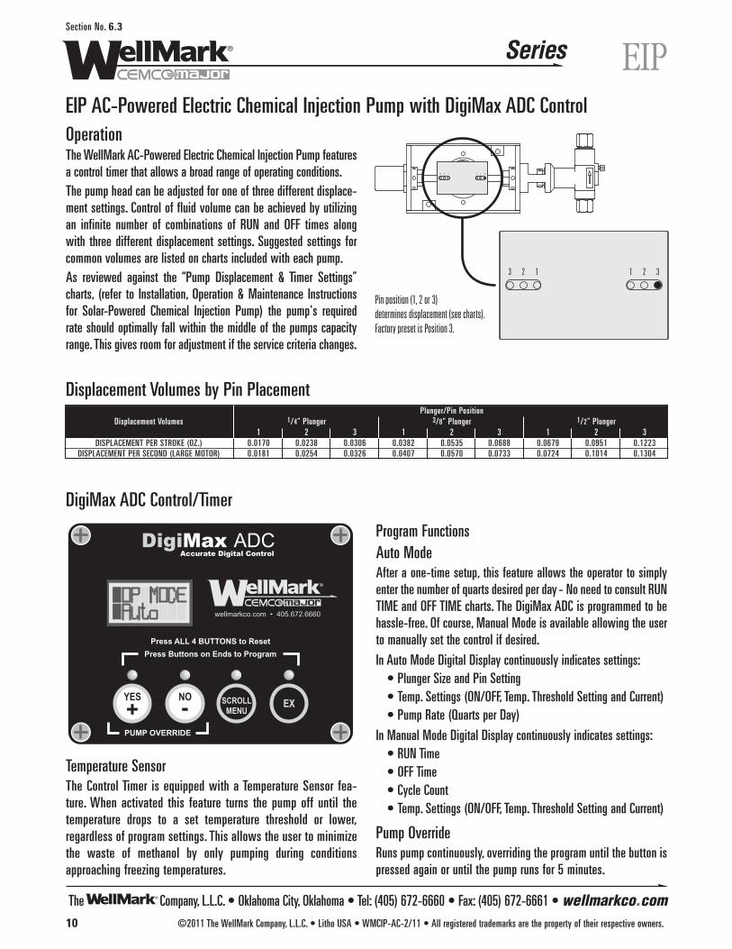
The Company, L.L.C. • Oklahoma City, Oklahoma • Tel: (405) 672-6660 • Fax: (405) 672-6661 • wellmarkco.com
Series
10 ©2011 The WellMark Company, L.L.C. • Litho USA • WMCIP-AC-2/11 • All registered trademarks are the property of their respective owners.
EIPSection No. 6.3
EIP AC-Powered Electric Chemical Injection Pump with DigiMax ADC ControlOperationThe WellMark AC-Powered Electric Chemical Injection Pump featuresa control timer that allows a broad range of operating conditions.The pump head can be adjusted for one of three different displace-ment settings. Control of fluid volume can be achieved by utilizingan infinite number of combinations of RUN and OFF times alongwith three different displacement settings. Suggested settings forcommon volumes are listed on charts included with each pump.As reviewed against the “Pump Displacement & Timer Settings”charts, (refer to Installation, Operation & Maintenance Instructionsfor Solar-Powered Chemical Injection Pump) the pump's requiredrate should optimally fall within the middle of the pumps capacityrange. This gives room for adjustment if the service criteria changes.
Temperature SensorThe Control Timer is equipped with a Temperature Sensor fea-ture. When activated this feature turns the pump off until thetemperature drops to a set temperature threshold or lower,regardless of program settings. This allows the user to minimizethe waste of methanol by only pumping during conditionsapproaching freezing temperatures.
Program FunctionsAuto ModeAfter a one-time setup, this feature allows the operator to simplyenter the number of quarts desired per day - No need to consult RUNTIME and OFF TIME charts. The DigiMax ADC is programmed to behassle-free. Of course, Manual Mode is available allowing the userto manually set the control if desired.
In Auto Mode Digital Display continuously indicates settings:• Plunger Size and Pin Setting• Temp. Settings (ON/OFF, Temp. Threshold Setting and Current)• Pump Rate (Quarts per Day)
In Manual Mode Digital Display continuously indicates settings:• RUN Time• OFF Time• Cycle Count• Temp. Settings (ON/OFF, Temp. Threshold Setting and Current)
Pump OverrideRuns pump continuously, overriding the program until the button ispressed again or until the pump runs for 5 minutes.
Pin position (1, 2 or 3) determines displacement (see charts).Factory preset is Position 3.
123 321
123 321
NOYES SCROLLMENU
EX
PUMP OVERRIDE
Press Buttons on Ends to ProgramPress ALL 4 BUTTONS to Reset
wellmarkco.com • 405.672.6660
DigiMax ADCAccurate Digital Control
+ -
Displacement Volumes by Pin Placement
DigiMax ADC Control/Timer
Plunger/Pin PositionDisplacement Volumes 1/4" Plunger 3/8" Plunger 1/2" Plunger
1 2 3 1 2 3 1 2 3DISPLACEMENT PER STROKE (OZ.) 0.0170 0.0238 0.0306 0.0382 0.0535 0.0688 0.0679 0.0951 0.1223
DISPLACEMENT PER SECOND (LARGE MOTOR) 0.0181 0.0254 0.0326 0.0407 0.0570 0.0733 0.0724 0.1014 0.1304
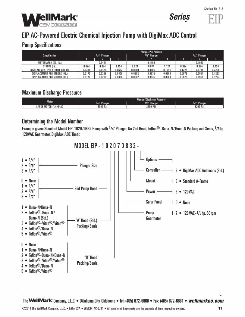
The Company, L.L.C. • Oklahoma City, Oklahoma • Tel: (405) 672-6660 • Fax: (405) 672-6661 • wellmarkco.com
Series
©2011 The WellMark Company, L.L.C. • Litho USA • WMCIP-AC-2/11 • All registered trademarks are the property of their respective owners. 11
EIPSection No. 6.3
EIP AC-Powered Electric Chemical Injection Pump with DigiMax ADC ControlPump Specifications
Plunger/Pin PositionSpecification 1/4" Plunger 3/8" Plunger 1/2" Plunger
1 2 3 1 2 3 1 2 3PISTON AREA (SQ. IN.) 0.0491 0.1104 0.1963
STROKE (IN.) 0.624 0.874 1.124 0.624 0.874 1.124 0.624 0.874 1.124DISPLACEMENT PER STROKE (CU. IN) 0.0306 0.0429 0.0562 0.0689 0.0965 0.1241 0.1225 0.1716 0.2206
DISPLACEMENT PER STROKE (OZ.) 0.0170 0.0238 0.0306 0.0382 0.0535 0.0688 0.0679 0.0951 0.1223DISPLACEMENT PER SECOND (OZ.) 0.0170 0.0238 0.0306 0.0382 0.0535 0.0688 0.0679 0.0951 0.1223
“A” Head (Std.)Packing/Seals
“B” HeadPacking/Seals
1 • 1/4"2 • 3/8"3 • 1/2"
0 • None1 • 1/4"2 • 3/8"3 • 1/2"
1 • Buna-N/Buna-N2 • Teflon®-Buna-N/
Buna-N (Std.)3 • Teflon®-Viton®/Viton®
4 • Teflon®/Buna-N5 • Teflon®/Viton®
0 • None1 • Buna-N/Buna-N2 • Teflon®-Buna-N/Buna-N3 • Teflon®-Viton®/Viton®
4 • Teflon®/Buna-N5 • Teflon®/Viton®
2 • DigiMax ADC Automatic (Std.)
3 • Standard A-Frame
8 • 120VAC
0 • None
7 • 120VAC-1/6 hp, 60rpm
MODEL EIP - 1 0 2 0 7 0 8 3 2 -
2nd Pump Head
Plunger SizeOptions
Controller
Mount
Power
Solar Panel
Pump Gearmotor
Determining the Model NumberExample given: Standard Model EIP-102070832 Pump with 1/4” Plunger, No 2nd Head, Teflon®-Buna-N/Buna-N Packing and Seals, 1/6hp120VAC Gearmotor, DigiMax ADC Timer.
Maximum Discharge PressuresMotor
Plunger/Discharge Pressure1/4" Plunger 3/8" Plunger 1/2" Plunger
LARGE MOTOR - 1/6 HP AC 5000 PSI 2500 PSI 1200 PSI

The Company, L.L.C. • Oklahoma City, Oklahoma • Tel: (405) 672-6660 • Fax: (405) 672-6661 • wellmarkco.com
Series
12 ©2011 The WellMark Company, L.L.C. • Litho USA • WMCIP-AC-2/11 • All registered trademarks are the property of their respective owners.
EIPSection No. 6.3
EIP AC-Powered Electric Chemical Injection Pump with DigiMax ADC Control
1/6 hpAC Gearmotor
Cover and Hardware
34
33
35
4
1514
1011
12
131
1912
1110
4118
1716
31
32
337
26
25
39
24
23
22
21
20
28
24
23
25
27
3029
98
540
638
372
3
AC-Powered Pump Component Parts & Parts ListItem Description Qty. Part No.
1 HOUSING 1 06500-72192 SCREW 2 05000-16923 HEX NUT 2 100074 MOTOR -1/6 HP 115VAC, 60 HERTZ 1 06000-94115 ECCENTRIC WHEEL 1 06500-72096 SET SCREW 2 05000-22947 LOCK WASHER 7 107098 BEARING 1 06000-84779 RECIPROCATING BLOCK 1 05013-6995
10 BUSHING 2 05013-701211 O-RING 2 1101712 GUIDE NUT 2 05013-702013 GUIDE 1 05013-698614 JAM NUT 1 05013-696815 CAP 1 05013-7119
1/4" 1 05013-690716 FLUID END 3/8" 1 05013-6909
1/2" 1 05013-69051/4" 1 06000-9293
17 PACKING SET-TEFLON®/BUNA-N* 3/8" 1 06000-93011/2" 1 06000-93191/4" 1 05013-7005
18 GLAND NUT 3/8" 1 05013-70011/2" 1 05013-70071/4" 1 05013-6975
19 PLUNGER 3/8" 1 05013-69771/2" 1 05013-6979
20 BALL -1/4" 1 06000-0265*Other packing materials available. Consult factory for information.
Item Description Qty. Part No.21 O-RING 1 1046022 SEAT 1 05013-695023 O-RING 2 05000-006624 BALL - 3/8" 2 06000-026725 O-RING 2 05000-005826 DISCHARGE VALVE BODY 1 05013-694227 SUCTION VALVE BODY 1 05013-693428 BLEED SCREW 1 05013-155829 PIN 2 001000-P30 HOUSING COVER 1 05013-713631 WING NUT 2 05000-564232 PUMP BASE 1 05013-714233 SCREW, SOCKET HEAD 8 05000-564834 DIGIMAX ADC CONTROL AND HOUSING 1 06000-639535 FLAT WASHER 4 007124-P38 SCREW 3 05000-564639 SPRING 1 1060640 SPACER 1 05013-754341 PACKING COVER 1 05013-7527
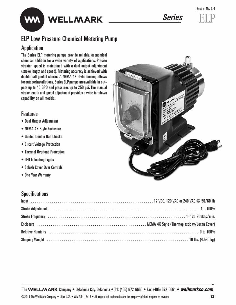
The Company • Oklahoma City, Oklahoma • Tel: (405) 672-6660 • Fax: (405) 672-6661 • wellmarkco.com©2014 The WellMark Company • Litho USA • WMELP-12/13 • All registered trademarks are the property of their respective owners. 13
ELP Low Pressure Chemical Metering PumpApplicationThe Series ELP metering pumps provide reliable, economicalchemical addition for a wide variety of applications. Precisestroking speed is maintained with a dual output adjustment(stroke length and speed). Metering accuracy is achieved withdouble ball guided checks. A NEMA 4X style housing allowsfor outdoor installations. Series ELP pumps areavailable in out-puts up to 45 GPD and pressures up to 250 psi. The manualstroke length and speed adjustment provides a wide turndowncapability on all models.
Features• Dual Output Adjustment
• NEMA 4X Style Enclosure
• Guided Double Ball Checks
• Circuit Voltage Protection
• Thermal Overload Protection
• LED Indicating Lights
• Splash Cover Over Controls
• One Year Warranty
SpecificationsInput . . . . . . . . . . . . . . . . . . . . . . . . . . . . . . . . . . . . . . . . . . . . . . . . . . . . . . . . . . . . . . . . 12 VDC, 120 VAC or 240 VAC @ 50/60 Hz
Stroke Adjustment . . . . . . . . . . . . . . . . . . . . . . . . . . . . . . . . . . . . . . . . . . . . . . . . . . . . . . . . . . . . . . . . . . . . . . . . . . . . . . . 10-100%
Stroke Frequency . . . . . . . . . . . . . . . . . . . . . . . . . . . . . . . . . . . . . . . . . . . . . . . . . . . . . . . . . . . . . . . . . . . . . . . . 1-125 Strokes/min.
Enclosure . . . . . . . . . . . . . . . . . . . . . . . . . . . . . . . . . . . . . . . . . . . . . . . . . . . . . . . . . NEMA 4X Style (Thermoplastic w/Lexan Cover)
Relative Humidity . . . . . . . . . . . . . . . . . . . . . . . . . . . . . . . . . . . . . . . . . . . . . . . . . . . . . . . . . . . . . . . . . . . . . . . . . . . . . . 0 to 100%
Shipping Weight . . . . . . . . . . . . . . . . . . . . . . . . . . . . . . . . . . . . . . . . . . . . . . . . . . . . . . . . . . . . . . . . . . . . . . . . . . 10 lbs. (4.536 kg)
Series ELPSection No. 6.4

The Company • Oklahoma City, Oklahoma • Tel: (405) 672-6660 • Fax: (405) 672-6661 • wellmarkco.com14 ©2014 The WellMark Company • Litho USA • WMELP-12/13 • All registered trademarks are the property of their respective owners.
ELP Low Pressure Chemical Metering Pump
1 • 3/8" (9.525 mm) Tubing,110 psi (Kynar® Head only)
2 • 1/4" (6.35 mm) Tubing, 250 psi (Kynar® Head only)
3 • 3/8" (9.525 mm) Tubing,250 psi (Kynar® Head only)
P • 1/4" (6.35 mm) MNPT Connections
C • Ceramic (standard)S • Stainless
V • Viton®
F • Teflon® (standard)H • Hypalon®
130 • 30 GPD/4.70 LPH@ 110 psi (7.5 bar)
217 • 17 GPD / 2.60 LPH@ 250 psi (17.2 bar)
X • Standard
1 • 120 Volt USA Plug4 • 12 Volt Operation
K • Kynar®
S • Stainless (standard)
*Other options available, please contact factory.
MODEL ELP 217 X 1-S F C 2
SeriesSection No. 6.4
ELP
Determining the Model NumberExample given: Standard Model ELP217X1-SFC2, Series ELP, Standard Control Options, 120 Volt USA Plug, Stainless Head Material,Teflon® Seats and Ceramic Check Ball, 1/4" (6.35 mm) Tubing Connections for 17 GPD/2.60 LPH with Max. Output @ 250 psi.
Connections
Output (Maximum)*
Control Options*
Voltage*
Head Material Check Ball
Seat Material
6.75"171.5 mm
4.13"105 mm
8"203.2 mm
5"127 mm
Dimensional Data
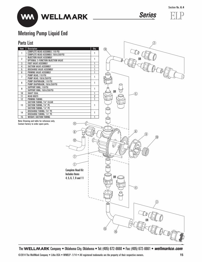
The Company • Oklahoma City, Oklahoma • Tel: (405) 672-6660 • Fax: (405) 672-6661 • wellmarkco.com©2014 The WellMark Company • Litho USA • WMELP-1/14 • All registered trademarks are the property of their respective owners. 15
Series ELPSection No. 6.4
Metering Pump Liquid End
Complete Head KitIncludes Items4, 5, 6, 7, 8 and 11
OR
OR
OR
OR
7
14
2
3
1
11
5
4
89
10
1315
6
12
Parts ListItem Description Qty.
1COMPLETE HEAD ASSEMBLY, 110 PSI
1COMPLETE HEAD ASSEMBLY, 150 & 250 PSI
2INJECTION VALVE ASSEMBLYOPTIONAL 3-FUNCTION INJECTION VALVE
1
3 FOOT VALVE ASSEMBLY 14 SUCTION VALVE ASSEMBLY 15 DISCHARGE VALVE ASSEMBLY 16 PRIMING VALVE ASSEMBLY 1
7PUMP HEAD, 110 PSIPUMP HEAD, 150 & 250 PSI
1
8PUMP DIAPHRAGM, 110 PSI
1PUMP DIAPHRAGM, 150 & 250 PSI
9SUPPORT RING, 110 PSI
1SUPPORT RING, 150 & 250 PSI
10 SHAFT SEAL 111 HEAD BOLTS 212 PRIMING TUBING 1
SUCTION TUBING, 3/8" CLEAR13 SUCTION TUBING, 3/8" PE 1
SUCTION TUBING, 1/4" PE
14DISCHARGE TUBING, 3/8" PE
1DISCHARGE TUBING, 1/4" PE
15 WEIGHT, SUCTION TUBING 1
Note: Drawing and table for reference only. Contact factory to order spare parts.
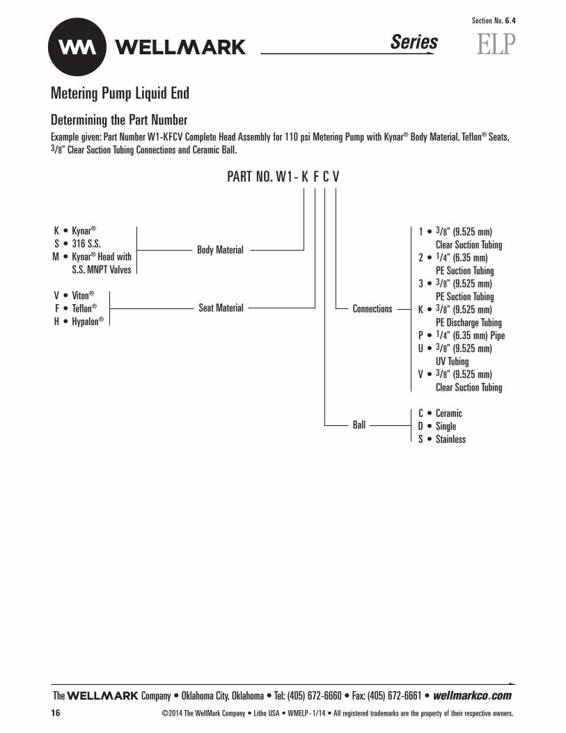
Metering Pump Liquid End
1 • 3/8" (9.525 mm) Clear Suction Tubing
2 • 1/4" (6.35 mm) PE Suction Tubing
3 • 3/8" (9.525 mm) PE Suction Tubing
K • 3/8" (9.525 mm) PE Discharge Tubing
P • 1/4" (6.35 mm) Pipe U • 3/8" (9.525 mm)
UV TubingV • 3/8" (9.525 mm)
Clear Suction Tubing
C • CeramicD • SingleS • Stainless
K • Kynar®
S • 316 S.S.M • Kynar® Head with
S.S. MNPT Valves
V • Viton®
F • Teflon®
H • Hypalon®
PART NO. W1- K F C V
Determining the Part NumberExample given: Part Number W1-KFCV Complete Head Assembly for 110 psi Metering Pump with Kynar® Body Material, Teflon® Seats,3/8" Clear Suction Tubing Connections and Ceramic Ball.
Connections
Body Material
Seat Material
Ball
The Company • Oklahoma City, Oklahoma • Tel: (405) 672-6660 • Fax: (405) 672-6661 • wellmarkco.com16 ©2014 The WellMark Company • Litho USA • WMELP-1/14 • All registered trademarks are the property of their respective owners.
SeriesSection No. 6.4
ELP
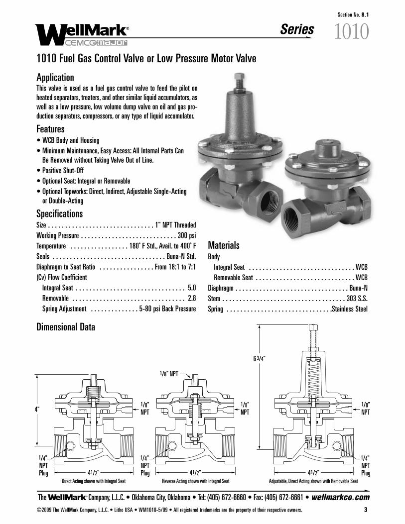
The Company, L.L.C. • Oklahoma City, Oklahoma • Tel: (405) 672-6660 • Fax: (405) 672-6661 • wellmarkco.com
Series
Reverse Acting shown with Integral SeatDirect Acting shown with Integral Seat Adjustable, Direct Acting shown with Removable Seat41/2"
63/4"
41/2"
1/8" NPT
1/8"NPT
1/4" NPTPlug
1/4" NPTPlug
1/4" NPTPlug
4"
41/2"
1/8"NPT
1/8"NPT
©2009 The WellMark Company, L.L.C. • Litho USA • WM1010-5/09 • All registered trademarks are the property of their respective owners. 3
����Section No. 8.1
1010 Fuel Gas Control Valve or Low Pressure Motor Valve
ApplicationThis valve is used as a fuel gas control valve to feed the pilot onheated separators, treaters, and other similar liquid accumulators, aswell as a low pressure, low volume dump valve on oil and gas pro-duction separators, compressors, or any type of liquid accumulator.
Features• WCB Body and Housing• Minimum Maintenance, Easy Access: All Internal Parts Can
Be Removed without Taking Valve Out of Line.• Positive Shut-Off• Optional Seat: Integral or Removable• Optional Topworks: Direct, Indirect, Adjustable Single-Acting
or Double-Acting
SpecificationsSize . . . . . . . . . . . . . . . . . . . . . . . . . . . . . . . 1" NPT ThreadedWorking Pressure . . . . . . . . . . . . . . . . . . . . . . . . . . . . 300 psiTemperature . . . . . . . . . . . . . . . . . 180˚ F Std., Avail. to 400˚ FSeals . . . . . . . . . . . . . . . . . . . . . . . . . . . . . . . . . Buna-N Std.Diaphragm to Seat Ratio . . . . . . . . . . . . . . . . From 18:1 to 7:1(Cv) Flow Coefficient
Integral Seat . . . . . . . . . . . . . . . . . . . . . . . . . . . . . . . . 5.0Removable . . . . . . . . . . . . . . . . . . . . . . . . . . . . . . . . . 2.8Spring Adjustment . . . . . . . . . . . . . . 5-80 psi Back Pressure
Materials Body
Integral Seat . . . . . . . . . . . . . . . . . . . . . . . . . . . . . . . WCBRemovable Seat . . . . . . . . . . . . . . . . . . . . . . . . . . . . . WCB
Diaphragm . . . . . . . . . . . . . . . . . . . . . . . . . . . . . . . . . Buna-NStem . . . . . . . . . . . . . . . . . . . . . . . . . . . . . . . . . . . . 303 S.S.Spring . . . . . . . . . . . . . . . . . . . . . . . . . . . . . . .Stainless Steel
Dimensional Data
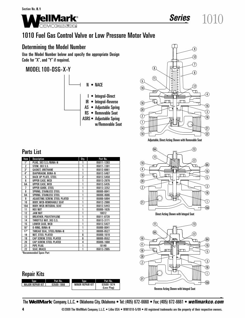
The Company, L.L.C. • Oklahoma City, Oklahoma • Tel: (405) 672-6660 • Fax: (405) 672-6661 • wellmarkco.com
Series
4 ©2009 The WellMark Company, L.L.C. • Litho USA • WM1010-5/09 • All registered trademarks are the property of their respective owners.
����Section No. 8.1
1010 Fuel Gas Control Valve or Low Pressure Motor Valve
Determining the Model NumberUse the Model Number below and specify the appropriate DesignCode for “X”, and “Y” if required.
Parts ListItem Description Qty. Part No.1* PLUG, 303 S.S./BUNA-N 1 05011-12932 STEM, 303 S.S. 1 05011-13013* GASKET, URETHANE 1 05012-68614* DIAPHRAGM, BUNA-N 1 05012-54675 BACK UP PLATE, STEEL 2 05012-54596 UPPER CASE, WCB 1 05013-2979
6A UPPER CASE, WCB 1 05012-54357 UPPER GUIDE, STEEL 1 05013-32528 SPRING, STAINLESS STEEL 1 06000-8841
8A SPRING, STAINLESS STEEL 1 06000-46869 ADJUSTING SCREW, STEEL PLATED 1 05000-5894
10 BODY, WCB-REMOVABLE SEAT 1 05012-298810A BODY, WCB-INTEGRAL SEAT 1 05012-544311 HEX NUT 1 05000-163512 JAM NUT 1 1001213 BREATHER, POLYETHYLENE 1 05011-872814 THROTTLE NUT, 303 S.S. 1 05013-317115 LOWER CASE, WCB 1 05012-542716* O-RING, BUNA-N 1 05000-004117* THREAD SEAL, STEEL/BUNA-N 1 06000-852718 NUT, STEEL PLATED 6 05000-161919 CAP SCREW, STEEL PLATED 6 06000-855220 CAP SCREW, STEEL PLATED 4 05000-166821 PIPE PLUG 1 1014922 SEAT, BRASS 1 05013-2995
*Recommended Spare Part
N • NACE
I • Integral-DirectIR • Integral-Reverse
AS • Adjustable SpringRS • Removable Seat
ASRS • Adjustable Spring w/Removable Seat
MODEL 100-DSG-X-Y
20
4
18
1917
11
8A 13
6A
15
5
3
16
1
10A
21
21
20
2
2
4
18
19
8A 17
11 13
6A
15
5
3
16
1
10A
20
2
18
19
5
8
11
17
6
12
7
9
1
14
10 22
21
16
3
15
4
Reverse Acting Shown with Integral Seat
Direct Acting Shown with Integral Seat
Adjustable, Direct Acting Shown with Removable Seat
Type Part No.MAJOR REPAIR KIT 03500-1866
Type Part No.MINOR REPAIR KIT 03500-1874
(Less Plug)
Repair Kits
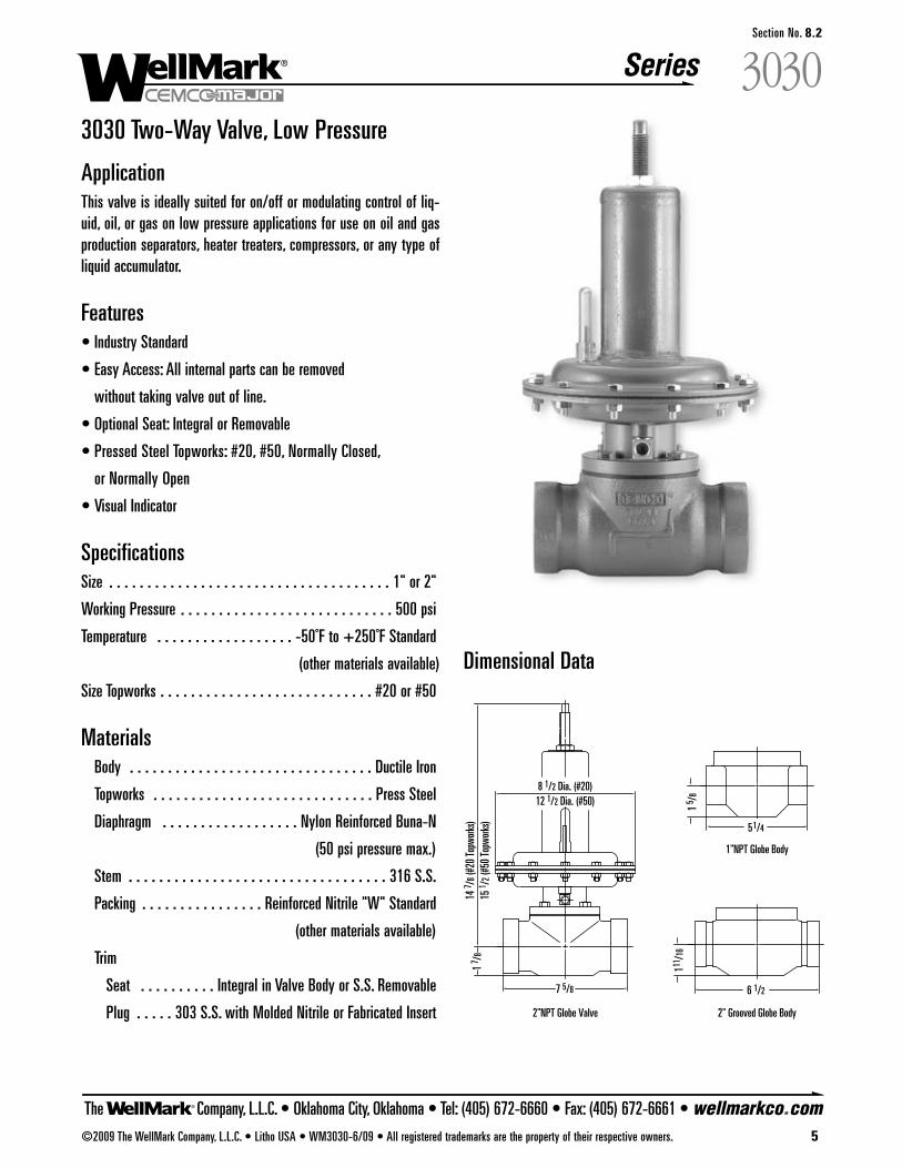
The Company, L.L.C. • Oklahoma City, Oklahoma • Tel: (405) 672-6660 • Fax: (405) 672-6661 • wellmarkco.com
Series
©2009 The WellMark Company, L.L.C. • Litho USA • WM3030-6/09 • All registered trademarks are the property of their respective owners. 5
3030Section No. 8.2
3030 Two-Way Valve, Low Pressure
ApplicationThis valve is ideally suited for on/off or modulating control of liq-uid, oil, or gas on low pressure applications for use on oil and gasproduction separators, heater treaters, compressors, or any type ofliquid accumulator.
Features• Industry Standard
• Easy Access: All internal parts can be removed
without taking valve out of line.
• Optional Seat: Integral or Removable
• Pressed Steel Topworks: #20, #50, Normally Closed,
or Normally Open
• Visual Indicator
SpecificationsSize . . . . . . . . . . . . . . . . . . . . . . . . . . . . . . . . . . . . . 1" or 2"
Working Pressure . . . . . . . . . . . . . . . . . . . . . . . . . . . . 500 psi
Temperature . . . . . . . . . . . . . . . . . . -50˚F to +250˚F Standard
(other materials available)
Size Topworks . . . . . . . . . . . . . . . . . . . . . . . . . . . . #20 or #50
Materials Body . . . . . . . . . . . . . . . . . . . . . . . . . . . . . . . . Ductile Iron
Topworks . . . . . . . . . . . . . . . . . . . . . . . . . . . . . Press Steel
Diaphragm . . . . . . . . . . . . . . . . . . Nylon Reinforced Buna-N
(50 psi pressure max.)
Stem . . . . . . . . . . . . . . . . . . . . . . . . . . . . . . . . . . 316 S.S.
Packing . . . . . . . . . . . . . . . . Reinforced Nitrile "W" Standard
(other materials available)
Trim
Seat . . . . . . . . . . Integral in Valve Body or S.S. Removable
Plug . . . . . 303 S.S. with Molded Nitrile or Fabricated Insert
Dimensional Data
14 7 /
8 (#2
0 To
pwork
s)15
1 /2 (
#50
Topw
orks)
8 1/2 Dia. (#20)12 1/2 Dia. (#50)
2"NPT Globe Valve
1"NPT Globe Body
2" Grooved Globe Body
7 5/8
51/4
111/1
6 1
5 /8
1 7 /
8
6 1/2
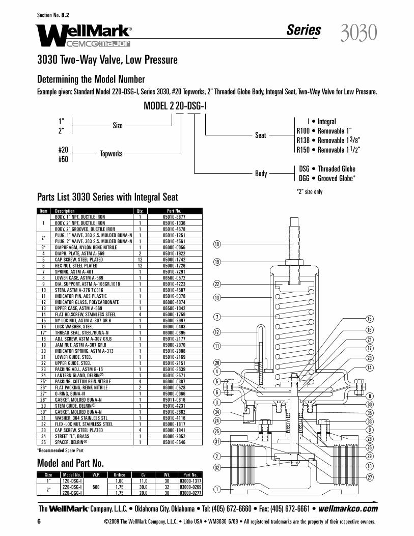
The Company, L.L.C. • Oklahoma City, Oklahoma • Tel: (405) 672-6660 • Fax: (405) 672-6661 • wellmarkco.com
Series
6 ©2009 The WellMark Company, L.L.C. • Litho USA • WM3030-6/09 • All registered trademarks are the property of their respective owners.
3030Section No. 8.2
3030 Two-Way Valve, Low Pressure
I • IntegralR100 • Removable 1"R138 • Removable 13/8"R150 • Removable 11/2"
DSG • Threaded GlobeDGG • Grooved Globe*
*2" size only
1"2"
#20#50
MODEL 2 20-DSG-I
Topworks
SizeSeat
Body
Determining the Model NumberExample given: Standard Model 220-DSG-I, Series 3030, #20 Topworks, 2" Threaded Globe Body, Integral Seat, Two-Way Valve for Low Pressure.
Parts List 3030 Series with Integral SeatItem Description Qty. Part No.
BODY, 1" NPT, DUCTILE IRON 1 05010-88771 BODY, 2" NPT, DUCTILE IRON 1 05010-1336
BODY, 2" GROOVED, DUCTILE IRON 1 05010-4678
2* PLUG, 1" VALVE, 303 S.S. MOLDED BUNA-N 1 05010-1251PLUG, 2" VALVE, 303 S.S. MOLDED BUNA-N 1 05010-4561
3* DIAPHRAGM, NYLON RENF. NITRILE 1 06000-00564 DIAPH. PLATE, ASTM A-569 2 05010-19225 CAP SCREW, STEEL PLATED 12 05000-17426 HEX NUT, STEEL PLATED 12 05000-17267 SPRING, ASTM A-401 1 05010-72918 LOWER CASE, ASTM A-569 1 06500-05729 DIA. SUPPORT, ASTM A-108GR.1018 1 05010-4223
10 STEM, ASTM A-276 TY.316 1 05010-458711 INDICATOR PIN, ABS PLASTIC 1 05010-537812 INDICATOR GLASS, POLYCARBONATE 1 06000-407413 UPPER CASE, ASTM A-569 1 06500-104214 FLAT HD.SCREW, STAINLESS STEEL 4 05000-175915 NY-LOC NUT, ASTM A-307 GR.B 1 05000-299716 LOCK WASHER, STEEL 1 06000-040317* THREAD SEAL, STEEL/BUNA-N 1 06000-039518 ADJ. SCREW, ASTM A-307 GR.B 1 05010-217719 JAM NUT, ASTM A-307 GR.B 1 05000-207020 INDICATOR SPRING, ASTM A-313 1 05010-288821 LOWER GUIDE, STEEL 1 05010-216922 UPPER GUIDE, STEEL 1 05010-215123 PACKING ADJ., ASTM B-16 1 05010-363924 LANTERN GLAND, DELRIN® 1 05010-357125* PACKING, COTTON REIN.NITRILE 4 06000-038726* FLAT PACKING, REINF. NITRILE 2 06000-052827* O-RING, BUNA-N 1 05000-006628* GASKET, MOLDED BUNA-N 1 05011-081629 STEM GUIDE, DELRIN® 1 05010-423130* GASKET, MOLDED BUNA-N 1 05010-366231 WASHER, 304 STAINLESS STL 1 05010-411632 FLEX-LOC NUT, STAINLESS STEEL 1 05000-181733 CAP SCREW, STEEL PLATED 4 05000-184134 STREET "L", BRASS 1 06000-205235 SPACER, DELRIN® 1 05010-8646
*Recommended Spare Part
Model and Part No.Size Model No. W.P. Orifice Cv Wt. Part No.1" 120-DSG-I 1.00 11.0 30 03000-1317
2" 220-DSG-I 500 1.75 30.0 32 03000-0269220-DGG-I 1.75 20.0 30 03000-0277
1
2
27
32
31
25
18
19
22
13
7
12
11
20
5
6
3
144
15
16
17
21
8
10
29
28
33
9
30
23
26
24
34 35
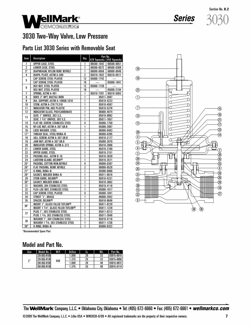
The Company, L.L.C. • Oklahoma City, Oklahoma • Tel: (405) 672-6660 • Fax: (405) 672-6661 • wellmarkco.com
Series
©2009 The WellMark Company, L.L.C. • Litho USA • WM3030-6/09 • All registered trademarks are the property of their respective owners. 7
3030Section No. 8.2
3030 Two-Way Valve, Low Pressure
2732
31
25
18
19
22
7
12
11
20
5
6
3
144
15
16
1721
10
29
28
339
30
23
26
2434 35
8
1
2
3638
37
3913
Parts List 3030 Series with Removable SeatItem Description Qty. Part No.
#20 Topworks #50 Topworks1 UPPER CASE, STEEL 1 06500-1042 06500-00512 LOWER CASE, STEEL 1 06500-0572 06500-03093* DIAPHRAGM, NYLON RENF. NITRILE 1 06000-0056 06000-00494 DIAPH. PLATE, ASTM A-569 2 05010-1922 05010-0411
5 CAP SCREW, STEEL PLATED 12 05000-1742 —CAP SCREW, STEEL PLATED 16 — 05000-1841
6 HEX NUT, STEEL PLATED 12 05000-1726 —HEX NUT, STEEL PLATED 16 — 05000-2104
7 SPRING, ASTM A-401 1 05010-7291 05010-50638 BODY, 2" NPT, DUCTILE IRON 1 05011-26979 DIA. SUPPORT, ASTM A-108GR.1018 1 05010-4223
10 STEM, ASTM A-276 TY.316 1 05010-458711 INDICATOR PIN, ABS PLASTIC 1 05010-537812 INDICATOR GLASS, POLYCARBONATE 1 06000-4074
13 SEAT, 1" ORIFICE, 303 S.S. 1 05010-9982SEAT, 1 3/8" ORIFICE, 303 S.S. 1 05011-1657
14 FLAT HD. SCREW, STAINLESS STEEL 4 05000-175915 NY-LOC NUT, ASTM A-307 GR.B 1 05000-299716 LOCK WASHER, STEEL 1 06000-040317* THREAD SEAL, STEEL/BUNA-N 1 06000-039518 ADJ. SCREW, ASTM A-307 GR.B 1 05010-217719 JAM NUT, ASTM A-307 GR.B 1 05000-207020 INDICATOR SPRING, ASTM A-313 1 05010-288821 LOWER GUIDE, STEEL 1 05010-216922 UPPER GUIDE, STEEL 1 05010-215123 PACKING ADJ., ASTM B-16 1 05010-363924 LANTERN GLAND, DELRIN® 1 05010-357125* PACKING, COTTON REIN.NITRILE 4 06000-038726* FLAT PACKING, REINF. NITRILE 2 06000-052827* O-RING, BUNA-N 1 05000-006628* GASKET, MOLDED BUNA-N 1 05011-081629 STEM GUIDE, DELRIN® 1 05010-423130* GASKET, MOLDED BUNA-N 1 05010-366231 WASHER, 304 STAINLESS STEEL 1 05010-411632 FLEX-LOC NUT, STAINLESS STEEL 1 05000-181733 CAP SCREW, STEEL PLATED 4 05000-184134 STREET "L", BRASS 1 06000-205235 SPACER, DELRIN® 1 05010-8646
36* INSERT 1", GLASS FILLED TEFLON® 1 05011-0220INSERT 1 3/8", GLASS FILLED TEFLON® 1 05011-1228
37 PLUG 1", 303 STAINLESS STEEL 1 05011-0212PLUG 1 3/8, 303 STAINLESS STEEL 1 05011-2648
38WASHER 1", 304 STAINLESS STEEL 1 05010-4116WASHER 1 3/8, 303 STAINLESS STEEL 1 05011-1236
39* O-RING, BUNA-N 1 05000-0322
*Recommended Spare Part
Model and Part No.Size Model No. W.P. Orifice Cv Wt. Part No.
220-DSG-R100 1.000 20 33 03015-0015
2" 220-DSG-R138 500 1.375 25 33 03015-0056250-DSG-R100 1.000 20 48 03015-0072250-DSG-R138 1.375 25 48 03015-0114
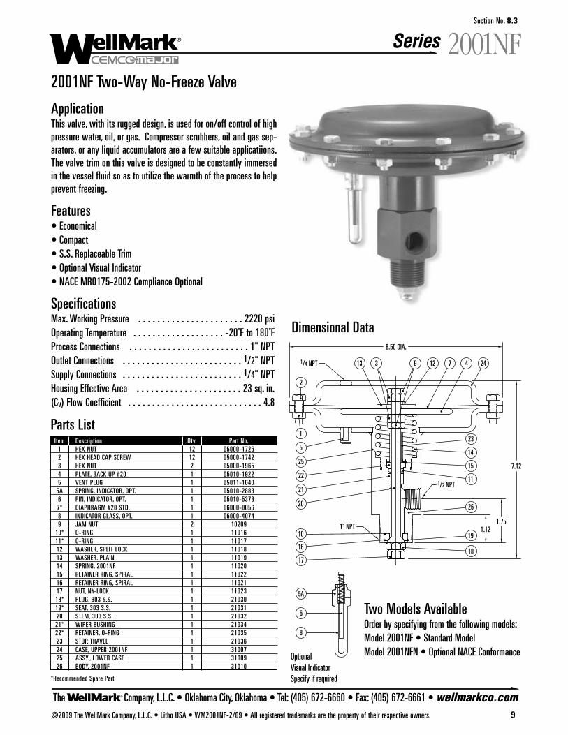
The Company, L.L.C. • Oklahoma City, Oklahoma • Tel: (405) 672-6660 • Fax: (405) 672-6661 • wellmarkco.com
Series 2001NF
©2009 The WellMark Company, L.L.C. • Litho USA • WM2001NF-2/09 • All registered trademarks are the property of their respective owners. 9
Section No. 8.3
2001NF Two-Way No-Freeze Valve
ApplicationThis valve, with its rugged design, is used for on/off control of highpressure water, oil, or gas. Compressor scrubbers, oil and gas sep-arators, or any liquid accumulators are a few suitable applicatiions.The valve trim on this valve is designed to be constantly immersedin the vessel fluid so as to utilize the warmth of the process to helpprevent freezing.
Features• Economical• Compact• S.S. Replaceable Trim• Optional Visual Indicator• NACE MR0175-2002 Compliance Optional
SpecificationsMax. Working Pressure . . . . . . . . . . . . . . . . . . . . . . 2220 psi Operating Temperature . . . . . . . . . . . . . . . . . . . -20˚F to 180˚FProcess Connections . . . . . . . . . . . . . . . . . . . . . . . . . 1" NPT Outlet Connections . . . . . . . . . . . . . . . . . . . . . . . . . 1/2" NPTSupply Connections . . . . . . . . . . . . . . . . . . . . . . . . . 1/4" NPTHousing Effective Area . . . . . . . . . . . . . . . . . . . . . . 23 sq. in.(Cv) Flow Coefficient . . . . . . . . . . . . . . . . . . . . . . . . . . . . 4.8
Dimensional Data
OptionalVisual IndicatorSpecify if required
313 9 12 7 4 24
23
5A
6
8
1
2
10
16
17
14
15
11
26
19
18
5
25
20
21
227.12
1/4 NPT
1/2 NPT
1.121.75
8.50 DIA.
1" NPT
Parts ListItem Description Qty. Part No.
1 HEX NUT 12 05000-17262 HEX HEAD CAP SCREW 12 05000-17423 HEX NUT 2 05000-19654 PLATE, BACK UP #20 1 05010-19225 VENT PLUG 1 05011-1640
5A SPRING, INDICATOR, OPT. 1 05010-28886 PIN, INDICATOR, OPT. 1 05010-53787* DIAPHRAGM #20 STD. 1 06000-00568 INDICATOR GLASS, OPT. 1 06000-40749 JAM NUT 2 10209
10* O-RING 1 1101611* O-RING 1 1101712 WASHER, SPLIT LOCK 1 1101813 WASHER, PLAIN 1 1101914 SPRING, 2001NF 1 1102015 RETAINER RING, SPIRAL 1 1102216 RETAINER RING, SPIRAL 1 1102117 NUT, NY-LOCK 1 1102318* PLUG, 303 S.S. 1 2103019* SEAT, 303 S.S. 1 2103120 STEM, 303 S.S. 1 2103221* WIPER BUSHING 1 2103422* RETAINER, O-RING 1 2103523 STOP, TRAVEL 1 2103624 CASE, UPPER 2001NF 1 3100725 ASSY., LOWER CASE 1 3100926 BODY, 2001NF 1 31010
*Recommended Spare Part
Two Models AvailableOrder by specifying from the following models:Model 2001NF • Standard ModelModel 2001NFN • Optional NACE Conformance
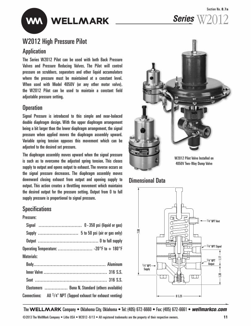
ApplicationThe Series W2012 Pilot can be used with both Back PressureValves and Pressure Reducing Valves. The Pilot will control pressure on scrubbers, separators and other liquid accumulatorswhere the pressure must be maintained at a constant level. When used with Model 4050V (or any other motor valve), the W2012 Pilot can be used to maintain a constant field adjustable pressure setting.
OperationSignal Pressure is introduced to this simple and near-balaced double diaphragm design. With the upper diaphragm arrangementbeing a bit larger than the lower diaphragm arrangement, the signalpressure when applied moves the diaphragm assembly upward.Variable spring tension opposes this movement which can be adjusted to the desired set pressure.
The diaphragm assembly moves upward when the signal pressureis such as to overcome the adjusted spring tension. This closes supply to output and opens output to exhaust. The reverse occurs asthe signal pressure decreases. The diaphragm assembly moves downward closing exhaust from output and opening supply to output. This action creates a throttling movement which maintainsthe desired output for the pressure setting. Output from 0 to full supply pressure is proportional to signal pressure.
SpecificationsPressure:
Signal . . . . . . . . . . . . . . . . . . . . . . . . . . . . . . 0 - 350 psi (liquid or gas)
Supply . . . . . . . . . . . . . . . . . . . . . . . . . . . . 5 to 50 psi (air or gas only)
Output . . . . . . . . . . . . . . . . . . . . . . . . . . . . . . . . . . . . . . . . . . 0 to full supply
Operating Temperature: . . . . . . . . . . . . . . . . . . . . . . . . -20°F to + 180°F
Materials:
Body. . . . . . . . . . . . . . . . . . . . . . . . . . . . . . . . . . . . . . . . . . . . . . . . . . Aluminum
Inner Valve . . . . . . . . . . . . . . . . . . . . . . . . . . . . . . . . . . . . . . . . . . . . 316 S.S.
Seat . . . . . . . . . . . . . . . . . . . . . . . . . . . . . . . . . . . . . . . . . . . . . . . . . . 316 S.S.
Elastomers . . . . . . . . . . . . . . . . Buna N, Standard (others available)
Connections: All 1/4" NPT (Tapped exhaust for exhaust venting) Ø 3.25
1/4" NPT Supply
1/4" NPT Output
1/4" NPT Signal
1/4" NPT Vent1.1
7
7.08
1.38
Section No. 8.7a
W2012 High Pressure Pilot
W2012
Dimensional Data
W2012 Pilot Valve Installed on 4050V Two-Way Dump Valve
Series
The Company • Oklahoma City, Oklahoma • Tel: (405) 672-6660 • Fax: (405) 672-6661 • wellmarkco.com©2013 The WellMark Company • Litho USA • W2012-8/13 • All registered trademarks are the property of their respective owners. 11
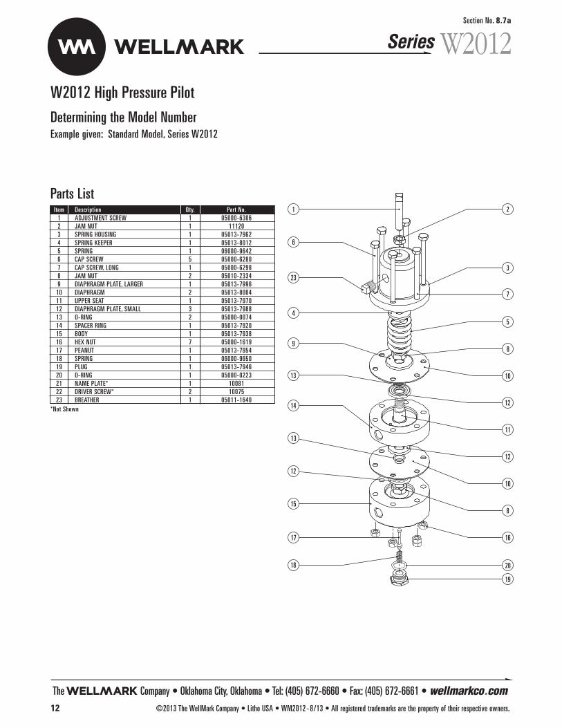
Section No. 8.7a
W2012W2012 High Pressure Pilot
Determining the Model NumberExample given: Standard Model, Series W2012
1
6
23
4
9
13
14
13
12
15
17
18
2
3
7
5
8
10
12
11
12
10
8
16
20
19
Parts ListItem Description Qty. Part No.1 ADJUSTMENT SCREW 1 05000-63062 JAM NUT 1 111203 SPRING HOUSING 1 05013-79624 SPRING KEEPER 1 05013-80125 SPRING 1 06000-96426 CAP SCREW 5 05000-62807 CAP SCREW, LONG 1 05000-62988 JAM NUT 2 05010-23349 DIAPHRAGM PLATE, LARGER 1 05013-799610 DIAPHRAGM 2 05013-800411 UPPER SEAT 1 05013-797012 DIAPHRAGM PLATE, SMALL 3 05013-798813 O-RING 2 05000-007414 SPACER RING 1 05013-792015 BODY 1 05013-793816 HEX NUT 7 05000-161917 PEANUT 1 05013-795418 SPRING 1 06000-965019 PLUG 1 05013-794620 O-RING 1 05000-022321 NAME PLATE* 1 1008122 DRIVER SCREW* 2 1007523 BREATHER 1 05011-1640
*Not Shown
Series
The Company • Oklahoma City, Oklahoma • Tel: (405) 672-6660 • Fax: (405) 672-6661 • wellmarkco.com12 ©2013 The WellMark Company • Litho USA • WM2012-8/13 • All registered trademarks are the property of their respective owners.
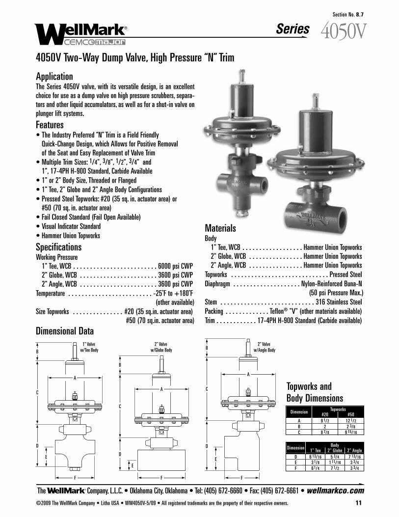
F
D
C
1" Valve w/Tee Body
E
B
A
A
F
E
D
2" Valve w/Globe Body
B
C
F
D
C
2" Valve w/Angle Body
E
B
A
4050V Two-Way Dump Valve, High Pressure “N” Trim
ApplicationThe Series 4050V valve, with its versatile design, is an excellentchoice for use as a dump valve on high pressure scrubbers, separa-tors and other liquid accumulators, as well as for a shut-in valve onplunger lift systems.
Features• The Industry Preferred “N” Trim is a Field Friendly
Quick-Change Design, which Allows for Positive Removal of the Seat and Easy Replacement of Valve Trim
• Multiple Trim Sizes: 1/4", 3/8", 1/2", 3/4" and1", 17-4PH H-900 Standard, Carbide Available
• 1" or 2" Body Size, Threaded or Flanged• 1" Tee, 2" Globe and 2" Angle Body Configurations• Pressed Steel Topworks: #20 (35 sq. in. actuator area) or
#50 (70 sq. in. actuator area)• Fail Closed Standard (Fail Open Available)• Visual Indicator Standard• Hammer Union Topworks
SpecificationsWorking Pressure
1" Tee, WCB . . . . . . . . . . . . . . . . . . . . . . . . . 6000 psi CWP2" Globe, WCB . . . . . . . . . . . . . . . . . . . . . . . 3600 psi CWP2" Angle, WCB . . . . . . . . . . . . . . . . . . . . . . . 3600 psi CWP
Temperature . . . . . . . . . . . . . . . . . . . . . . . . . -25˚F to +180˚F (other available)
Size Topworks . . . . . . . . . . . . . . . #20 (35 sq.in. actuator area)#50 (70 sq.in. actuator area)
Dimensional Data
MaterialsBody
1" Tee, WCB . . . . . . . . . . . . . . . . . . Hammer Union Topworks2" Globe, WCB . . . . . . . . . . . . . . . . Hammer Union Topworks2" Angle, WCB . . . . . . . . . . . . . . . . Hammer Union Topworks
Topworks . . . . . . . . . . . . . . . . . . . . . . . . . . . . . Pressed SteelDiaphragm . . . . . . . . . . . . . . . . . . . . Nylon-Reinforced Buna-N
(50 psi Pressure Max.)Stem . . . . . . . . . . . . . . . . . . . . . . . . . . . . 316 Stainless SteelPacking . . . . . . . . . . . . . Teflon® "V" (other materials available)Trim . . . . . . . . . . . . 17-4PH H-900 Standard (Carbide available)
Dimension Topworks#20 #50
A 9 1/2 12 1/2
B 2 2 3/8C 8 7/8 9 15/16
Dimension Body1" Tee 2" Globe 2" Angle
D 6 13/16 5 3/4 7 13/16E 3 1/8 1 11/16 3 3/4F 6 1/4 7 1/2 3 3/4
Topworks and Body Dimensions
The Company, L.L.C. • Oklahoma City, Oklahoma • Tel: (405) 672-6660 • Fax: (405) 672-6661 • wellmarkco.com
Series 4050V
©2009 The WellMark Company • Litho USA • WM4050V-5/09 • All registered trademarks are the property of their respective owners. 11
Section No. 8.7
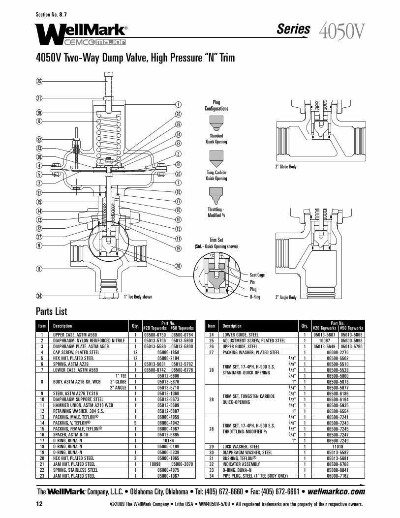
The Company, L.L.C. • Oklahoma City, Oklahoma • Tel: (405) 672-6660 • Fax: (405) 672-6661 • wellmarkco.com
Series
12 ©2009 The WellMark Company • Litho USA • WM4050V-5/09 • All registered trademarks are the property of their respective owners.
4050VSection No. 8.7
4050V Two-Way Dump Valve, High Pressure “N” Trim
2” Globe Body
StandardQuick Opening
Throttling - Modified %
PlugConfigurations
Tung. CarbideQuick Opening
2” Angle Body1” Tee Body shown
Seat Cage
Trim Set(Std. - Quick Opening shown)
Plug
O-Ring
Pin
25
21
26
6
32
23
30
4
5
2
31
15
14
12
22
27
9
20
1
29
24
33
3
30
20
7
18
17
16
10
13
11
19
288
34
Parts ListItem Description Qty. Part No.
#20 Topworks #50 Topworks1 UPPER CASE, ASTM A569 1 06500-6750 06500-67842 DIAPHRAGM, NYLON REINFORCED NITRILE 1 05013-5706 05013-59003 DIAPHRAGM PLATE, ASTM A569 1 05013-5590 05013-58004 CAP SCREW, PLATED STEEL 12 05000-18585 HEX NUT, PLATED STEEL 12 05000-21046 SPRING, ASTM A229 1 05013-5631 05013-57827 LOWER CASE, ASTM A569 1 06500-6742 06500-6776
1" TEE 1 05012-66068 BODY, ASTM A216 GR. WCB 2" GLOBE 1 05013-5876
2" ANGLE 1 05013-67189 STEM, ASTM A276 TY.316 1 05013-1068
10 DIAPHRAGM SUPPORT, STEEL 1 05013-567311 HAMMER UNION, ASTM A216 WCB 1 05013-569912 RETAINING WASHER, 304 S.S. 1 05012-688713 PACKING, MALE, TEFLON® 1 06000-495914 PACKING, V, TEFLON® 5 06000-494215 PACKING, FEMALE, TEFLON® 1 06000-496716 SPACER, ASTM B-16 1 05012-689517 O-RING, BUNA-N 1 1013618 O-RING, BUNA-N 1 05000-019919 O-RING, BUNA-N 1 05000-533920 HEX NUT, PLATED STEEL 2 05000-196521 JAM NUT, PLATED STEEL 1 10098 05000-207022 SPRING, STAINLESS STEEL 1 06000-497523 JAM NUT, PLATED STEEL 1 05000-1967
Item Description Qty. Part No.#20 Topworks #50 Topworks
24 LOWER GUIDE, STEEL 1 05013-5607 05013-586825 ADJUSTMENT SCREW, PLATED STEEL 1 10097 05000-599826 UPPER GUIDE, STEEL 1 05013-5649 05013-579027 PACKING WASHER, PLATED STEEL 1 06000-2276
1/4" 1 06500-5502
TRIM SET, 17-4PH, H-900 S.S.3/8" 1 06500-5510
28 1/2" 1 06500-5528STANDARD-QUICK OPENING 3/4" 1 06500-58001" 1 06500-5818
1/4" 1 06500-5677
TRIM SET, TUNGSTEN CARBIDE3/8" 1 06500-6186
28 1/2" 1 06500-6194QUICK-OPENING 3/4" 1 06500-59351" 1 06500-6554
1/4" 1 06500-7241
TRIM SET, 17-4PH, H-900 S.S.3/8" 1 06500-7243
28 1/2" 1 06500-7245THROTTLING-MODIFIED % 3/4" 1 06500-72471" 1 06500-7249
29 LOCK WASHER, STEEL 1 1101830 DIAPHRAGM WASHER, STEEL 1 05013-558231 BUSHING, TEFLON® 1 05013-568132 INDICATOR ASSEMBLY 1 06500-676833 O-RING, BUNA-N 1 05000-004134 PIPE PLUG, STEEL (1” TEE BODY ONLY) 1 06000-7162
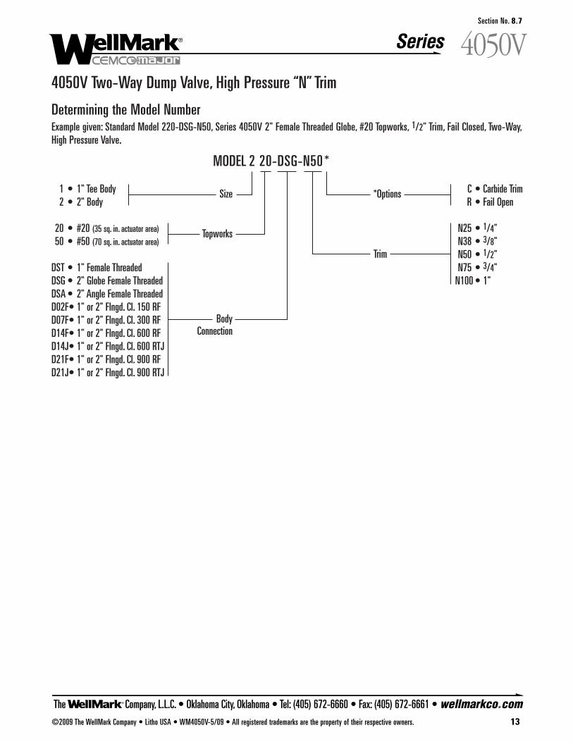
4050V Two-Way Dump Valve, High Pressure “N” Trim
Determining the Model NumberExample given: Standard Model 220-DSG-N50, Series 4050V 2" Female Threaded Globe, #20 Topworks, 1/2" Trim, Fail Closed, Two-Way,High Pressure Valve.
C • Carbide TrimR • Fail Open
N25 • 1/4"N38 • 3/8"N50 • 1/2"N75 • 3/4"
N100 • 1"
1 • 1" Tee Body2 • 2" Body
20 • #20 (35 sq. in. actuator area)50 • #50 (70 sq. in. actuator area)
DST • 1" Female ThreadedDSG • 2" Globe Female ThreadedDSA • 2" Angle Female ThreadedD02F• 1" or 2" Flngd. Cl. 150 RFD07F• 1" or 2" Flngd. Cl. 300 RFD14F• 1" or 2" Flngd. Cl. 600 RFD14J• 1" or 2" Flngd. Cl. 600 RTJD21F• 1" or 2" Flngd. Cl. 900 RFD21J• 1" or 2" Flngd. Cl. 900 RTJ
MODEL 2 20-DSG-N50 *
Size *Options
Trim
Body Connection
Topworks
The Company, L.L.C. • Oklahoma City, Oklahoma • Tel: (405) 672-6660 • Fax: (405) 672-6661 • wellmarkco.com
Series 4050V
©2009 The WellMark Company • Litho USA • WM4050V-5/09 • All registered trademarks are the property of their respective owners. 13
Section No. 8.7
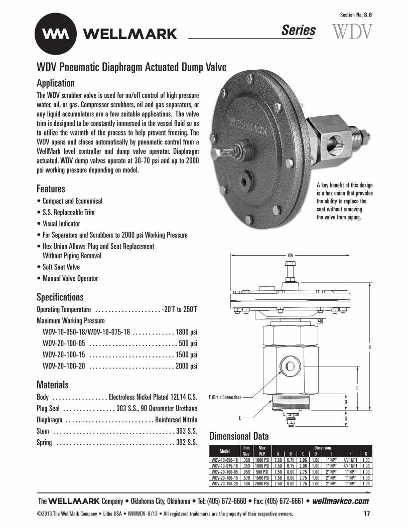
WDVSection No. 8.8
WDV Pneumatic Diaphragm Actuated Dump ValveApplicationThe WDV scrubber valve is used for on/off control of high pressurewater, oil, or gas. Compressor scrubbers, oil and gas separators, orany liquid accumulators are a few suitable applications. The valvetrim is designed to be constantly immersed in the vessel fluid so asto utilize the warmth of the process to help prevent freezing. TheWDV opens and closes automatically by pneumatic control from aWellMark level controller and dump valve operator. Diaphragmactuated, WDV dump valves operate at 30-70 psi and up to 2000psi working pressure depending on model.
Features• Compact and Economical
• S.S. Replaceable Trim
• Visual Indicator
• For Separators and Scrubbers to 2000 psi Working Pressure
• Hex Union Allows Plug and Seat Replacement Without Piping Removal
• Soft Seat Valve
• Manual Valve Operator
SpecificationsOperating Temperature . . . . . . . . . . . . . . . . . . . . -20˚F to 250˚F
Maximum Working Pressure
WDV-10-050-18/WDV-10-075-18 . . . . . . . . . . . . . 1800 psi
WDV-20-100-05 . . . . . . . . . . . . . . . . . . . . . . . . . . . 500 psi
WDV-20-100-15 . . . . . . . . . . . . . . . . . . . . . . . . . . 1500 psi
WDV-20-100-20 . . . . . . . . . . . . . . . . . . . . . . . . . . 2000 psi
Materials Body . . . . . . . . . . . . . . . . . Electroless Nickel Plated 12L14 C.S.
Plug Seal . . . . . . . . . . . . . . . . 303 S.S., 90 Durometer Urethane
Diaphragm . . . . . . . . . . . . . . . . . . . . . . . . . . . Reinforced Nitrile
Stem . . . . . . . . . . . . . . . . . . . . . . . . . . . . . . . . . . . . . 303 S.S.
Spring . . . . . . . . . . . . . . . . . . . . . . . . . . . . . . . . . . . . 302 S.S.
B
C
DF (Drain Connection)
GE
øA
A key benefit of this designis a hex union that providesthe ability to replace the seat without removing the valve from piping.
ModelTrim Max DimensionSize W.P. A B C D E F G
WDV-10-050-18 .359 1800 PSI 7.50 6.75 2.06 1.00 1" NPT 1/2" NPT 1.03WDV-10-075-18 .359 1800 PSI 7.50 6.75 2.06 1.00 1" NPT 3/4" NPT 1.03WDV-20-100-05 .859 500 PSI 7.50 8.00 2.75 1.00 2" NPT 1" NPT 1.03WDV-20-100-15 .576 1500 PSI 7.50 8.00 2.75 1.00 2" NPT 1" NPT 1.03WDV-20-100-20 .436 2000 PSI 7.50 8.00 2.75 1.00 2" NPT 1" NPT 1.03
Dimensional Data
The Company • Oklahoma City, Oklahoma • Tel: (405) 672-6660 • Fax: (405) 672-6661 • wellmarkco.com©2013 The WellMark Company • Litho USA • WMWDV-8/13 • All registered trademarks are the property of their respective owners. 17
Series
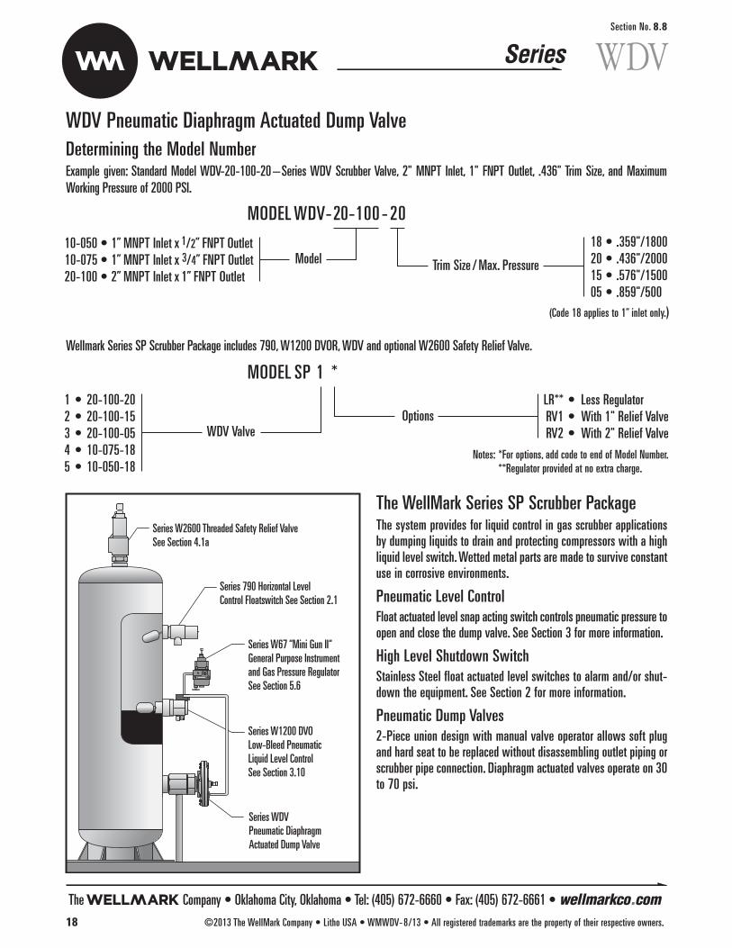
WDVSection No. 8.8
Wellmark Series SP Scrubber Package includes 790, W1200 DVOR, WDV and optional W2600 Safety Relief Valve.
WDV Pneumatic Diaphragm Actuated Dump Valve
Series 790 Horizontal LevelControl Floatswitch See Section 2.1
Series W2600 Threaded Safety Relief ValveSee Section 4.1a
Series W67 “Mini Gun II“General Purpose Instrument and Gas Pressure RegulatorSee Section 5.6
Series W1200 DVOLow-Bleed Pneumatic Liquid Level ControlSee Section 3.10
Series WDVPneumatic DiaphragmActuated Dump Valve
The WellMark Series SP Scrubber PackageThe system provides for liquid control in gas scrubber applicationsby dumping liquids to drain and protecting compressors with a highliquid level switch. Wetted metal parts are made to survive constantuse in corrosive environments.
Pneumatic Level ControlFloat actuated level snap acting switch controls pneumatic pressure toopen and close the dump valve. See Section 3 for more information.
High Level Shutdown SwitchStainless Steel float actuated level switches to alarm and/or shut-down the equipment. See Section 2 for more information.
Pneumatic Dump Valves2-Piece union design with manual valve operator allows soft plugand hard seat to be replaced without disassembling outlet piping orscrubber pipe connection. Diaphragm actuated valves operate on 30to 70 psi.
Determining the Model NumberExample given: Standard Model WDV-20-100-20–Series WDV Scrubber Valve, 2" MNPT Inlet, 1" FNPT Outlet, .436" Trim Size, and MaximumWorking Pressure of 2000 PSI.
18 • .359"/180020 • .436"/200015 • .576"/150005 • .859"/500
10-050 • 1” MNPT Inlet x 1/2” FNPT Outlet10-075 • 1” MNPT Inlet x 3/4” FNPT Outlet20-100 • 2” MNPT Inlet x 1” FNPT Outlet
MODELWDV-20-100 - 20
Model Trim Size /Max. Pressure
LR** • Less RegulatorRV1 • With 1" Relief ValveRV2 • With 2" Relief Valve
Notes: *For options, add code to end of Model Number.**Regulator provided at no extra charge.
1 • 20-100-202 • 20-100-153 • 20-100-054 • 10-075-185 • 10-050-18
MODEL SP 1 *
WDV ValveOptions
(Code 18 applies to 1” inlet only.)
The Company • Oklahoma City, Oklahoma • Tel: (405) 672-6660 • Fax: (405) 672-6661 • wellmarkco.com18 ©2013 The WellMark Company • Litho USA • WMWDV-8/13 • All registered trademarks are the property of their respective owners.
Series
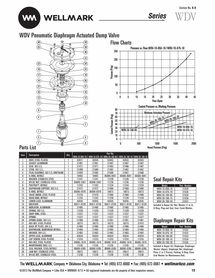
WDVSection No. 8.8
WDV Pneumatic Diaphragm Actuated Dump Valve
Parts ListItem Description Qty. Part No.
WDV-10-050-18 WDV-10-075-18 WDV-20-100-05 WDV-20-100-15 WDV-20-100-201 BODY, STEEL PLATED 1 42071 42044 42043 42043 420432 GASKET, ALUMINUM 1 21491 21491 21487 21487 214873 SEAT, 303 S.S. 1 21471 21471 21493 21496 214674 STEM, 303 S.S. 1 21489 21489 21482 21482 214825 PLUG ASSEMBLY, 303 S.S./URETHANE 1 21505 21505 21506 21507 215086 O-RING, NITRILE 1 10483 10483 05000-0041 05000-0041 05000-00417 WASHER, STAINLESS STEEL 1 11241 11241 11238 11238 112388 NYLOC NUT, STAINLESS STEEL 1 05000-2567 05000-2567 11236 11236 112369 POLYPAK®, NITRILE 1 11242 11242 11234 11234 1123410 DIAPHRAGM SUPPORT, 303 S.S. 1 21472 21472 21469 21469 2146911 O-RING, NITRILE 1 05000-0470 05000-0470 10073 10073 1007312 VALVE UNION, STEEL PLATED 1 21470 21470 21468 21468 2146813 QUAD RING, NITRILE 1 11243 11243 11239 11239 1123914 LOWER CASE, ALUMINUM 1 42035 42035 42035 42035 4203515 BREATHER 1 05011-8729 05011-8729 05011-8729 05011-8729 05011-872916 INDICATOR, ALUMINUM 1 21485 21485 21485 21485 2148517 SPRING, 302 S.S. 1 11229 11229 11229 11229 1122918 SNAP RING, STEEL 1 11237 11237 11237 11237 1123719 SPRING 1 11227 11227 11227 11227 1122720 SPRING GUIDE, 303 S.S. 1 21490 21490 21481 21481 2148121 HEX NUT, STEEL PLATED 1 10273 10273 10273 10273 2147322 BACK UP PLATE, 304 S.S. 1 21480 21480 21480 21480 2148023 DIAPHRAGM, REINFORCED NITRILE 1 21484 21484 21484 21484 2148424 WASHER, 304 S.S. 1 21483 21483 21483 21483 2148325 UPPER CASE, ALUMINUM 1 42034 42034 42034 42034 4203426 CAP SCREW, STEEL PLATED 8 11233 11233 11233 11233 1123327 HEX NUT, STEEL PLATED 8 05000-1619 05000-1619 05000-1619 05000-1619 05000-161928 MAINTENANCE BOLT, S.S. 1 11235 11235 11235 11235 1123529 SEAL WASHER, STEEL/NITRILE 1 06000-0395 06000-0395 06000-0395 06000-0395 06000-039530 JAM NUT, STAINLESS STEEL 1 10012 10012 10012 10012 1001231 NYLOC NUT, STAINLESS STEEL 1 11236 11236 11236 11236 11236
Model Part NumberWDV-10-050-18 21528WDV-10-075-18 21528WDV-20-100-05 21529WDV-20-100-15 21530WDV-20-100-20 21531
Included in Repair Kit: Nut, Washer (1 to 3),O-Ring, Plug and Seal, Seat, Crush Washer.
Seal Repair Kits
Model Part NumberWDV-10-050-18 21532WDV-10-075-18 21532WDV-20-100-05 21533WDV-20-100-15 21534WDV-20-100-20 21535
Included in Repair Kit: Diaphragm, DiaphragmWasher (Upper), Diaphragm Nut, DiaphragmPlate (1 or 2 Pieces), Packing, O-Ring, Stem,Seal Washer for Maintenance Bolt.
Diaphragm Repair Kits
28
29
30
25
26
31
2423
22
2127
1516
11 10
9
6
8
3
2
1 8
17
1 4 20
19
1213
5
7
4
1
Flow ChartsPressure vs. Flow WDV-10-050-18/ WDV-10-075-18
50 10 15 20Flow (Gpm)
25 30 35 40 45
250
Pres
sure
(Psig
)
200
150
100
50
0
Control Pressure vs. Working Pressure
500 1000Vessel Pressure (Psig)
1500 20000
7080
6050403020100
Contr
ol Pr
essu
re (P
sig)
WDV-20-100-05WDV-10-050-18 WDV-10-075-18
Minimum Activation Pressure
WDV-20-100-20
WDV-20-100-15
The Company • Oklahoma City, Oklahoma • Tel: (405) 672-6660 • Fax: (405) 672-6661 • wellmarkco.com©2013 The WellMark Company • Litho USA • WMWDV-8/13 • All registered trademarks are the property of their respective owners. 19
Series


Series
The Company, L.L.C. • Oklahoma City, Oklahoma • Tel: (405) 672-6660 • Fax: (405) 672-6661 • wellmarkco.com©2002 The WellMark Company • Litho USA • WM5050-9/02 • All registered trademarks are the property of their respective owners. 1
5050Section No. 9.1
5050 Two-Way Double Seated Valve (Balanced)ApplicationThese valves are used where higher flow is desired with little forcerequired to operate. These pilot operated double seated, near bal-anced, valves perform ideally for this service. Additionally, theyhave been used successfully on separators, meters, and waterknockouts, where a reduced signal pressure is available.
Features• Available in 2" Threaded; 2" 3", and 4" Flanged; Globe or Angle;
Ductile Iron
• Unique Buna’N or Viton Seat Plugs: Designed for high capacity,smooth flow, and positive sealing.
• SS Internal Wetted Parts
• Pressed Steel Topworks
SpecificationsSize 2" Threaded 2", 3", & 4" Flanged
Working Presure 400 psi 275 psi
Temperature . . . . . . . . . . . . . . . . . . .-50˚F to +250˚F Standard
(other materials available)
Size Topworks . . . . . . . . . . . . . . . . . . . . . . . . . . . . . . . . .#20
Material
Body . . . . . . . . . . . . . . . . . . . . . . . . . . . . . . . . .Ductile Iron
Topworks . . . . . . . . . . . . . . . . . . . . . . . . . . . . . .Press Steel
Diaphragm . . . . . . . . . . . . . . . . . . .Nylon Reinforced Buna-N
(50 psi pressure max.)
Stem . . . . . . . . . . . . . . . . . . . . . . . . . . . . . . . . . . .303 SS
Packing . . . . . . . . . . . . . . . . . . . . .Cotton Reinforced Buna-N
Trim . . . . . . . . . .Buna-N or Viton® Molded Plug, Integral Seat
Dimensional Data
7 3/4 4"
2",3"and 4" Flanged Globe Valve
2" NPT Globe Valve 2" NPT Angle Valve
17" A
pprox
.
17" A
pprox
.
3 7 /16
4
"A"
"D" D
ia.
"C"
"J" A
pprox
.
8 1/2 Dia.
8 1/2 Dia. 8 1/2 Dia.
General DimensionsSize “A” “C” “D” “J”2" 7 3/4" 3 7/16" 6" 17"3" 11" 4 1/4" 7 1/2" 18"4" 12 3/4" 5" 9" 19"

Series
The Company, L.L.C. • Oklahoma City, Oklahoma • Tel: (405) 672-6660 • Fax: (405) 672-6661 • wellmarkco.com2 ©2002 The WellMark Company • Litho USA • WM5050-9/02 • All registered trademarks are the property of their respective owners.
5050Section No. 9.1
5050 Two-Way Double Seated Valve (Balanced)Determining the Model NumberExample given: Standard Model 320-DFG-N – Series 5050 Two-Way Double Seated Valve, 3" Flanged, Globe Body, Buna-N Trim.
Parts List
33
34
29
30
28
2
8
9
4
12
1
3
13
16
21
20
26
2527
24
22
2331
32
36
15
14
17
7
6
10
5
35
19 18
11
37
Model and Part No.Size Model No. Body Cv Wt. Part No.
220-DSA-N 2"NPT, ANGLE 40 35 03000-14812" 220-DSG-N 2"NPT, GLOBE 40 41 03000-5771
220-DFG-N 2"FLANGED, GLOBE 40 43 03000-15073" 320-DFG-N 3"FLANGED, GLOBE 75 73 03000-15564" 420-DFG-N 4"FLANGED, GLOBE 110 115 03000-1614
Item Description Qty. Part No.2" 3" 4"
BODY, 2"NPT ANGLE, DUCTILE IRON 1 05010-12111 BODY, 2"NPT GLOBE, DUCTILE IRON 1 05012-3611
BODY, FLANGED GLOBE, DUCT. IRON 1 05010-6947 05010-4827 05010-5584
2 DIA. SUPPORT, STEEL 1 05010-6095DIA. SUPPORT, DUCTILE IRON 1 05010-1989 05010-1401
3* GASKET, MOLDED BUNA-N 1 05011-0816 05011-0857 05011-08404* BOTTOM PLUG, MOLDED BUNA-N 1 05010-1252 05010-1369 05010-13775* TOP PLUG, MOLDED BUNA-N 1 05010-1260 05011-2663 05011-26556 STEM, ASTM A-582 TY.303 1 05010-1435 05010-1419 05010-14277 SPACER, ASTM A-582 TY.303 1 05011-3455 05010-1443 05010-14688* GASKET, MOLDED BUNA-N 1 05010-3662 05010-45799 LINKAGE, ASTM A-582 TY.303 1 05010-1351 05010-1864
10 FLAT HD. SCREW, STAINLESS STEEL 4 05000-1759 05000-227811 HINGE PIN, STAINLESS STEEL 1 05010-2037 05010-202912 WASHER, ASTM A-582 TY.303 1 05010-1492 05010-145013 FLEX-LOC NUT, STAINLESS STEEL 1 05000-2062 05000-209614 LOWER CASE, ASTM A-569 1 06500-0572 06500-125715 COTTER PIN, MONEL 1 06000-0239 06000-024716 CAP SCREW, ASTM A-307 GR.B 4 05000-1841 05000-2013
17*PACKING, COTTON RENF. NITRILE 3 06000-0387PACKING, COTTON RENF. NITRILE 4 06000-0387
18* PACKING, FLAT, COTTON RENF. NITRILE 2 06000-052819 GLAND, LANTERN, DELRIN 1 05010-745720 PACKING ADJ., ASTM B-16 1 05010-363921 GLASS, IND., POLYCABONATE 1 06000-407422 DIAPH. PLATE, ASTM A-569 2 05010-192223* DIAPHRAGM, NYLON RENF.NITRILE 1 06000-005624* THREAD SEAL, STEEL/BUNA-N 1 06000-039525 LOWER GUIDE, ASTM A-108GR.1213 1 05010-216926 LOCK WASHER, STEEL 1 06000-040327 NY-LOC NUT, ASTM A-307 GR.B 1 05000-299728 SPRING, ASTM A-229 1 05010-729129 UPPER GUIDE, ASTM A-108GR. 1213 1 05010-215130 UPPER CASE, ASTM A-569 1 06500-104231 CAP SCREW, ASTM A-307 GR.B 12 05000-174232 HEX NUT, ASTM A-307 GR.B 12 05000-172633 ADJ. SCREW, ASTM A-307 GR.B 1 05010-340734 JAM NUT, ASTM A-307 GR.B 1 05000-207035 PIN,INDICATOR, ABS PLASTIC 1 05010-537836 SPRING, ASTM A-313 1 05010-288837 ELBOW, BRASS 1 06000-2052
*Recommended Spare Part
N • Buna-NV • Viton®
DSG • Threaded Globe*DSA • Threaded Angle*DFG • Flanged Globe
* Available in 2" Only
2 • 2"3 • 3"4 • 4"
20 • #20
MODEL 3 20-DFG-N
Size Trim
BodyTopworks

Series
The Company, L.L.C. • Oklahoma City, Oklahoma • Tel: (405) 672-6660 • Fax: (405) 672-6661 • wellmarkco.com©2002 The WellMark Company • Litho USA • WM3535-9/02 • All registered trademarks are the property of their respective owners. 1
3535Section No. 10.1
3535 Back Pressure Valve, Low Pressure, Single Seat
ApplicationWellMark’s Back Pressure Valve can be used in any installationwhere upstream pressure is required to be kept at a preset range.It may also be used as: a pressure relief valve, a custody transferdump valve to hold a certain back pressure, or as a separator backpressure valve on the gas or liquid side. Upstream pressure isapplied to the bottom of the diaphragm through connecting tubing.Spring tension above the diaphragm opposes this pressure, andwhen the pressure exceeds the pressure setting on the spring, theplug is raised off the seat. By varying the spring tension, the pres-sure setting can be varied.The typical application for these valves is to hold back pressure onseparators, treaters, Lact units, etc.
Features• Simple Design• Self-Contained:There are no pilots or small orifices to plug or freeze.• Easy Access: All internal parts can be removed without taking
valve out of line.• Optional Seat: Integral or Removable• Available in 1" and 2" Size• Pressed Steel Topworks• Threaded body, Ductile Iron• Flanged Body, Steel
SpecificationsSize . . . . . . . . . . . . . .1" & 2" Threaded, 2" Grooved, 2" FlangedWorking Presure . . . . . . . . . . . . . . . . Dictated by Spring RangeSpring Range . . . . . . . . . . . . . . . . . . . . . . . . From 0 to 150 psiTemperature . . . . . . . . . . . . . . . . . . -50˚F to +250˚F Standard
(other materials available)Size Topworks . . . . . . . . . . . . . . . . . . . . . . . . . . . . #10 or #20(CV) Flow Coefficient . . . . . . . . . . . . . . . . 1" = 11 2" = 25
MaterialBody . . . . . . . . . . . . . . . . . . . 1" & 2" Threaded Ductile Iron
2" Flanged WCBTopworks . . . . . . . . . . . . . . #20 Press Steel, #10 Steel WCBDiaphragm . . . . . . . . . . . . . . . . . . . Nylon Reinforced NitrileStem . . . . . . . . . . . . . . . . . . . . . . . . . . . . . . . . . . . 316 SSPacking . . . . . . . . . . . . . . . . . . . . . Cotton Reinforced NitrileTrim . . . . . . . . . . . . . . . . . . . . . . . . 303 SS Molded Buna-N
2"NPT Globe Valve
1"NPT Globe Body 2" Grooved Globe Body
1 11/1
6
7 1/2 Dia. (#10 Topworks)8 1/2 Dia. (#20 Topworks)
7 1/2 Dia. (#10 Topworks)8 1/2 Dia. (#20 Topworks)
Flow Flow
2" Flanged Globe Valve
6" D
ia. (2
" ANS
I 150
)
6 1 /2 "
Dia.
(2"A
NSI 3
00/6
00)
7 5/8
5 1/4
1 5 /8
1 7 /8
6 1/2
19 1 /
2 App
rox.
19 1 /
2 App
rox.
9 1/2
Dimensional Data

Series
The Company, L.L.C. • Oklahoma City, Oklahoma • Tel: (405) 672-6660 • Fax: (405) 672-6661 • wellmarkco.com2 ©2002 The WellMark Company • Litho USA • WM3535-9/02 • All registered trademarks are the property of their respective owners.
3535Section No. 10.1
3535 Back Pressure Valve, Low Pressure, Single Seat
Determining the Model NumberExample given: Standard Model 220-DSG-B-I–Series 3535, 2" ThreadedGlobe Body, #20 Topworks, Integral Seated Back Pressure Valve.
Parts List Series 3535 w/#20 Topworks
22
2331
10
Spring & Spring GuideFor 50-100# Models Only
10-80# 26
24
25
27
28
24
26
18
2120
25
30
12
34
5
6
7
8
9
1112
13
15
16
17
14
19
29
32
3334
35
Model and Part No.Size Model No. Ends Connection Spring Range Cv Wt. Part No.
1" 120-DSG-B-I1" NPT
0-30 lbs11 32#
03027-0003120-DSG-B-I 10-80 lbs 03027-0011220-DSG-B-I 0-30 lbs 03001-0086220-DSG-B-I 2" NPT 10-80 lbs 25 38# 03001-0094220-DSG-B-I 50-100 lbs 03001-0177220-DGG-B-I 0-30 lbs 03001-0037
2" 220-DGG-B-I 2" GROOVED 10-80 lbs 25 35# 03001-0052220-DGG-B-I 50-100 lbs 03001-0011220-DFG-B-I 0-30 lbs 03001-0144220-DFG-B-I 2"ANSI 150 RF 10-80 lbs 25 46# 03001-0151220-DFG-B-I 50-100 lbs 03001-0193
TrimI • Integral
R100 • 1" RemovableR138 • 1 3/8" RemovableR150 • 1 1/2" Removable
B • Back Pressure Valve
BodyDSG • Threaded GlobeDFG • Flanged Globe*
(Specify Flange Rating)DGG • Grooved Globe*
* Available in 2" Only
Size1 • 1"2 • 2"
Topworks10 • #1020 • #20
MODEL 220-DSG-B- I
Item Description Qty. Part No.BODY, 1"NPT, DUCTILE IRON 1 05011-8397
1 BODY, 2"NPT, DUCTILE IRON 1 05011-8256BODY, 2" GROOVED, DUCTILE IRON 1 05011-8207BODY, 2" ANSI 150RF, STEEL WCB 1 06500-3345
2* PLUG, 1" VALVES, 303SS MOLDED BUNA-N 1 05011-1251PLUG, 2" VALVES, 303SS MOLDED BUNA-N 1 05010-4561
3* GASKET, MOLDED BUNA-N 1 05011-08164 DIA. SUPPORT, ASTM A-108GR.1018 1 05010-43635 WASHER, 304 STAINLESS STL. 1 05010-41166 STEM, ASTM A-276 TY.316 1 05010-45877 FLEX-LOC NUT, STAINLESS STEEL 1 05000-18178 CAP SCREW, ASTM A-307 GR.B 4 05000-18589 O-RING, BUNA-N 1 05000-0066
10 FLAT HD. SCREW, STAINLESS STEEL 4 05000-175911 LOWER CASE, ASTM A-569 1 06500-057212 GASKET, MOLDED BUNA-N 1 05010-366213 BREATHER, HPE 1 05011-164014 UPPER CASE, ASTM A-569 1 06500-105915* THREAD SEAL, STEEL/BUNA-N 1 06000-039516* PACKING, FLAT, COTTON REIN. NITRILE 1 06000-052817 PACKING ADJ., ASTM B-16 1 05010-363918 SPACER, DELRIN 1 05010-432219* PACKING, COTTON REIN. NITRILE 3 06000-038720 LOCK WASHER, STEEL 1 06000-040321 NY-LOC NUT, ASTM A-307 GR.B 1 05000-299722 DIAPH. PLATE, ASTM A-569 2 05010-1922
23* DIAPHRAGM 0-30#, NYLON RENF. NITRILE 1 06000-0056DIAPH. 30-100#, NYLON RENF. NITRILE 1 06000-0064
24 UPPER GUIDE, ASTM A-108GR.1213 1 05010-1906UPPER GUIDE 50-100#, ASTM A-108GR.1213 1 05010-5071
25 LOWER GUIDE, ASTM A-366 1 05010-1914LOWER GUIDE 50-100#, ASTM A-366 1 05010-5089
26SPRING 0-30#, ASTM A-401 1 05010-1344SPRING 10-80#, ASTM A-401 1 05010-6293
27 ADJ. SCREW, ASTM A-307 GR.B 1 05010-782028 JAM NUT, ASTM A-307 GR.B 1 05000-207029 SPRING, ASTM A-401, INNER 1 05010-505530 CAP SCREW, ASTM A-307 GR.B 12 05000-174231 HEX NUT, ASTM A-307 GR.B 12 05000-172632 ELBOW, CONN., BRASS 1 06000-044533 CONNECTOR, BRASS 1 06000-042934 TUBING, COPPER 1 06000-043735 STEM GUIDE, DELRIN 1 05010-4231
*Recommended Spare Part
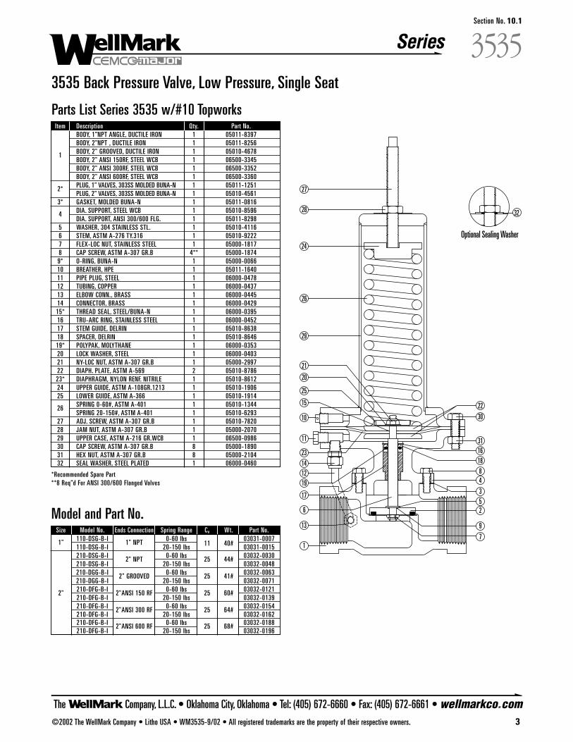
Series
The Company, L.L.C. • Oklahoma City, Oklahoma • Tel: (405) 672-6660 • Fax: (405) 672-6661 • wellmarkco.com©2002 The WellMark Company • Litho USA • WM3535-9/02 • All registered trademarks are the property of their respective owners. 3
3535Section No. 10.1
3535 Back Pressure Valve, Low Pressure, Single Seat
Parts List Series 3535 w/#10 Topworks
1
3
23
31
27
28
24
26
29
21
20
25
30
1618
22
19
17
15
Optional Sealing Washer
4
526
7
9
8
10
11
1214
13
32
Model and Part No.Size Model No. Ends Connection Spring Range Cv Wt. Part No.
1" 110-DSG-B-I 1" NPT 0-60 lbs11 40#
03031-0007110-DSG-B-I 20-150 lbs 03031-0015210-DSG-B-I 2" NPT 0-60 lbs 25 44# 03032-0030210-DSG-B-I 20-150 lbs 03032-0048210-DGG-B-I 2" GROOVED 0-60 lbs 25 41# 03032-0063210-DGG-B-I 20-150 lbs 03032-0071
2" 210-DFG-B-I 2"ANSI 150 RF 0-60 lbs 25 60# 03032-0121210-DFG-B-I 20-150 lbs 03032-0139210-DFG-B-I 2"ANSI 300 RF 0-60 lbs 25 64# 03032-0154210-DFG-B-I 20-150 lbs 03032-0162210-DFG-B-I 2"ANSI 600 RF 0-60 lbs 25 68# 03032-0188210-DFG-B-I 20-150 lbs 03032-0196
Item Description Qty. Part No.BODY, 1"NPT ANGLE, DUCTILE IRON 1 05011-8397BODY, 2"NPT , DUCTILE IRON 1 05011-8256
1 BODY, 2" GROOVED, DUCTILE IRON 1 05010-4678BODY, 2" ANSI 150RF, STEEL WCB 1 06500-3345BODY, 2" ANSI 300RF, STEEL WCB 1 06500-3352BODY, 2" ANSI 600RF, STEEL WCB 1 06500-3360
2* PLUG, 1" VALVES, 303SS MOLDED BUNA-N 1 05011-1251PLUG, 2" VALVES, 303SS MOLDED BUNA-N 1 05010-4561
3* GASKET, MOLDED BUNA-N 1 05011-0816
4 DIA. SUPPORT, STEEL WCB 1 05010-8596DIA. SUPPORT, ANSI 300/600 FLG. 1 05011-8298
5 WASHER, 304 STAINLESS STL. 1 05010-41166 STEM, ASTM A-276 TY.316 1 05010-92227 FLEX-LOC NUT, STAINLESS STEEL 1 05000-18178 CAP SCREW, ASTM A-307 GR.B 4** 05000-18749* O-RING, BUNA-N 1 05000-006610 BREATHER, HPE 1 05011-164011 PIPE PLUG, STEEL 1 06000-047812 TUBING, COPPER 1 06000-043713 ELBOW CONN., BRASS 1 06000-044514 CONNECTOR, BRASS 1 06000-042915* THREAD SEAL, STEEL/BUNA-N 1 06000-039516 TRU-ARC RING, STAINLESS STEEL 1 06000-045217 STEM GUIDE, DELRIN 1 05010-863818 SPACER, DELRIN 1 05010-864619* POLYPAK, MOLYTHANE 1 06000-035320 LOCK WASHER, STEEL 1 06000-040321 NY-LOC NUT, ASTM A-307 GR.B 1 05000-299722 DIAPH. PLATE, ASTM A-569 2 05010-878623* DIAPHRAGM, NYLON RENF. NITRILE 1 05010-861224 UPPER GUIDE, ASTM A-108GR.1213 1 05010-190625 LOWER GUIDE, ASTM A-366 1 05010-1914
26 SPRING 0-60#, ASTM A-401 1 05010-1344SPRING 20-150#, ASTM A-401 1 05010-6293
27 ADJ. SCREW, ASTM A-307 GR.B 1 05010-782028 JAM NUT, ASTM A-307 GR.B 1 05000-207029 UPPER CASE, ASTM A-216 GR.WCB 1 06500-098630 CAP SCREW, ASTM A-307 GR.B 8 05000-189031 HEX NUT, ASTM A-307 GR.B 8 05000-210432 SEAL WASHER, STEEL PLATED 1 06000-0460
*Recommended Spare Part**8 Req"d For ANSI 300/600 Flanged Valves

Series
The Company, L.L.C. • Oklahoma City, Oklahoma • Tel: (405) 672-6660 • Fax: (405) 672-6661 • wellmarkco.com4 ©2002 The WellMark Company • Litho USA • WM3535-9/02 • All registered trademarks are the property of their respective owners.
3535Section No. 10.1
3535 Back Pressure Valve, Low Pressure, Single Seat
Parts List Series 3535 w/Removable Seat & #10 Topworks
1
3
2331
27
28
24
26
29
21
20
25
30
16
18
22
19
17
15
*OPTIONAL SEALING WASHER
4
5
2
6
79
8
10
11
12
14
13
32
33
34
Item Description Qty. Part No.BODY, 2" ANSI 150RF, STEEL WCB 1 06500-3204
1 BODY, 2" ANSI 300RF, STEEL WCB 1 06500-3212BODY, 2" ANSI 600RF, STEEL WCB 1 06500-3220
2 CAP SCREW, ASTM A-307 GR.B 4** 05000-1874
3 DIA. SUPPORT ANSI 150 FLG., WCB 1 05010-8596DIA. SUPPORT ANSI 300/600, WCB 1 05011-8298
4* O-RING, BUNA-N 1 05000-03715 WASHER, 304 STAINLESS STL. 1 05010-41166 STEM, ASTM A-276 TY.316 1 05012-31817 FLEX-LOC NUT, STAINLESS STEEL 1 05000-18178* PLUG, 303SS MOLDED BUNA-N 1 05012-14589* O-RING, BUNA-N 1 05000-006610 BREATHER, HPE 1 05011-164011 PIPE PLUG, STEEL 1 06000-047812 TUBING, COPPER 1 06000-043713 ELBOW CONN., BRASS 1 06000-044514 CONNECTOR, BRASS 1 06000-042915* THREAD SEAL, STEEL/BUNA-N 1 06000-039516 TRU-ARC RING, STAINLESS STEEL 1 06000-045217 STEM GUIDE, DELRIN 1 05010-863818 SPACER, DELRIN 1 05010-864619* POLYPAK, MOLYTHANE 1 06000-035320 LOCK WASHER, STEEL 1 06000-040321 NY-LOC NUT, ASTM A-307 GR.B 1 05000-299722 DIAPH. PLATE, ASTM A-569 2 05010-878623* DIAPHRAGM, NYLON RENF. NITRILE 1 05010-861224 UPPER GUIDE, ASTM A-108GR.1213 1 05010-190625 LOWER GUIDE, ASTM A-366 1 05010-1914
26 SPRING 0-60#, ASTM A-401 1 05010-1344SPRING 20-150#, ASTM A-401 1 05010-6293
27 ADJ. SCREW, ASTM A-307 GR.B 1 05010-782028 JAM NUT, ASTM A-307 GR.B 1 05000-207029 UPPER CASE, ASTM A-216 GR.WCB 1 06500-098630 CAP SCREW, ASTM A-307 GR.B 8 05000-189031 HEX NUT, ASTM A-307 GR.B 8 05000-210432 SEAT, ASTM A-582 TY.303 1 05011-165733* O-RING, BUNA-N 1 05000-032234 SEAL WASHER, STEEL PLATED 1 06000-0460
*Recommended Spare Part**8 Req'd For ANSI 300/600 Flanged Valves
Model and Part No.Size/ANSI Model No. Spring Range Cv Wt. Part No.
2"-150 210-DFG-B-R138 0-60 lbs 25 61# 03032-0287210-DFG-B-R138 20-150 lbs 03032-0295
2"-300 210-DFG-B-R138 0-60 lbs 25 65# 03032-0303210-DFG-B-R138 20-150 lbs 03032-0220
2"-600 210-DFG-B-R138 0-60 lbs 25 69# 03032-0311210-DFG-B-R138 20-150 lbs 03032-0329
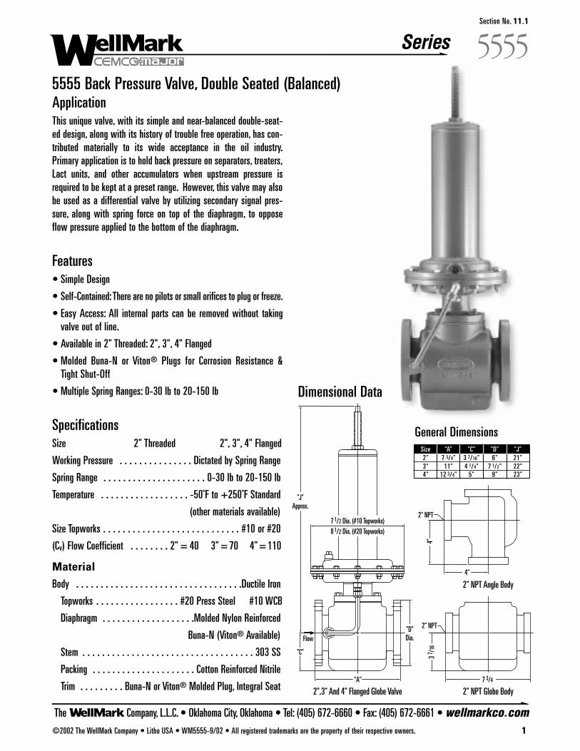
Series
The Company, L.L.C. • Oklahoma City, Oklahoma • Tel: (405) 672-6660 • Fax: (405) 672-6661 • wellmarkco.com©2002 The WellMark Company • Litho USA • WM5555-9/02 • All registered trademarks are the property of their respective owners. 1
5555Section No. 11.1
5555 Back Pressure Valve, Double Seated (Balanced)ApplicationThis unique valve, with its simple and near-balanced double-seat-ed design, along with its history of trouble free operation, has con-tributed materially to its wide acceptance in the oil industry.Primary application is to hold back pressure on separators, treaters,Lact units, and other accumulators when upstream pressure isrequired to be kept at a preset range. However, this valve may alsobe used as a differential valve by utilizing secondary signal pres-sure, along with spring force on top of the diaphragm, to opposeflow pressure applied to the bottom of the diaphragm.
Features• Simple Design
• Self-Contained:There are no pilots or small orifices to plug or freeze.
• Easy Access: All internal parts can be removed without takingvalve out of line.
• Available in 2" Threaded: 2", 3", 4" Flanged
• Molded Buna-N or Viton® Plugs for Corrosion Resistance &Tight Shut-Off
• Multiple Spring Ranges: 0-30 lb to 20-150 lb
SpecificationsSize 2" Threaded 2", 3", 4" Flanged
Working Pressure . . . . . . . . . . . . . . . Dictated by Spring Range
Spring Range . . . . . . . . . . . . . . . . . . . . . 0-30 lb to 20-150 lb
Temperature . . . . . . . . . . . . . . . . . . -50˚F to +250˚F Standard
(other materials available)
Size Topworks . . . . . . . . . . . . . . . . . . . . . . . . . . . . #10 or #20
(Cv) Flow Coefficient . . . . . . . . 2" = 40 3" = 70 4" = 110
MaterialBody . . . . . . . . . . . . . . . . . . . . . . . . . . . . . . . . . .Ductile Iron
Topworks . . . . . . . . . . . . . . . . . #20 Press Steel #10 WCB
Diaphragm . . . . . . . . . . . . . . . . . . .Molded Nylon Reinforced
Buna-N (Viton® Available)
Stem . . . . . . . . . . . . . . . . . . . . . . . . . . . . . . . . . . . 303 SS
Packing . . . . . . . . . . . . . . . . . . . . . Cotton Reinforced Nitrile
Trim . . . . . . . . . Buna-N or Viton® Molded Plug, Integral Seat
Dimensional Data
"D"Dia.
"A"
"C"
"J"Approx.
Flow
7 1/2 Dia. (#10 Topworks)8 1/2 Dia. (#20 Topworks)
7 3/4
4"
2" NPT
2" NPT
2" NPT Globe Body
2" NPT Angle Body
2",3" And 4" Flanged Globe Valve
3 7 /16
4"
General DimensionsSize “A” “C” “D” “J”2" 7 3/4" 3 7/16" 6" 21"3" 11" 4 1/4" 7 1/2" 22"4" 12 3/4" 5" 9" 23"
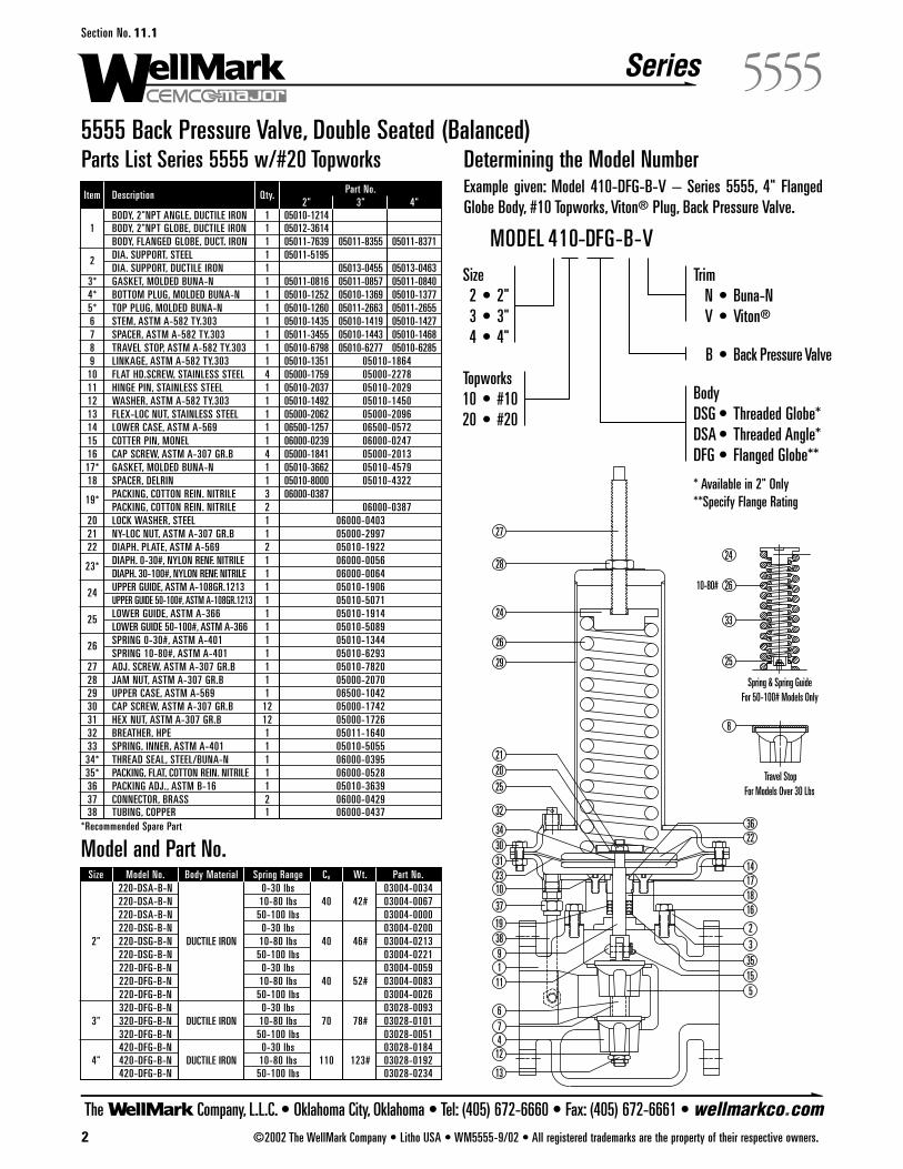
Series
The Company, L.L.C. • Oklahoma City, Oklahoma • Tel: (405) 672-6660 • Fax: (405) 672-6661 • wellmarkco.com2 ©2002 The WellMark Company • Litho USA • WM5555-9/02 • All registered trademarks are the property of their respective owners.
5555Section No. 11.1
5555 Back Pressure Valve, Double Seated (Balanced)Determining the Model NumberExample given: Model 410-DFG-B-V – Series 5555, 4" FlangedGlobe Body, #10 Topworks, Viton® Plug, Back Pressure Valve.
Parts List Series 5555 w/#20 Topworks
2
9
412
1
3
13
16
22
2331
15
76
10
511
Spring & Spring GuideFor 50-100# Models Only
10-80#
Travel StopFor Models Over 30 Lbs
8
33
26
24
25
32
27
28
24
26
29
1718
212025
19
3034
37
38
36
35
14Model and Part No.
Size Model No. Body Material Spring Range Cv Wt. Part No.220-DSA-B-N 0-30 lbs 03004-0034220-DSA-B-N 10-80 lbs 40 42# 03004-0067220-DSA-B-N 50-100 lbs 03004-0000220-DSG-B-N 0-30 lbs 03004-0200
2" 220-DSG-B-N DUCTILE IRON 10-80 lbs 40 46# 03004-0213220-DSG-B-N 50-100 lbs 03004-0221220-DFG-B-N 0-30 lbs 03004-0059220-DFG-B-N 10-80 lbs 40 52# 03004-0083220-DFG-B-N 50-100 lbs 03004-0026320-DFG-B-N 0-30 lbs 03028-0093
3" 320-DFG-B-N DUCTILE IRON 10-80 lbs 70 78# 03028-0101320-DFG-B-N 50-100 lbs 03028-0051420-DFG-B-N 0-30 lbs 03028-0184
4" 420-DFG-B-N DUCTILE IRON 10-80 lbs 110 123# 03028-0192420-DFG-B-N 50-100 lbs 03028-0234
Item Description Qty. Part No.2" 3" 4"
BODY, 2"NPT ANGLE, DUCTILE IRON 1 05010-12141 BODY, 2"NPT GLOBE, DUCTILE IRON 1 05012-3614
BODY, FLANGED GLOBE, DUCT. IRON 1 05011-7639 05011-8355 05011-8371
2 DIA. SUPPORT, STEEL 1 05011-5195DIA. SUPPORT, DUCTILE IRON 1 05013-0455 05013-0463
3* GASKET, MOLDED BUNA-N 1 05011-0816 05011-0857 05011-08404* BOTTOM PLUG, MOLDED BUNA-N 1 05010-1252 05010-1369 05010-13775* TOP PLUG, MOLDED BUNA-N 1 05010-1260 05011-2663 05011-26556 STEM, ASTM A-582 TY.303 1 05010-1435 05010-1419 05010-14277 SPACER, ASTM A-582 TY.303 1 05011-3455 05010-1443 05010-14688 TRAVEL STOP, ASTM A-582 TY.303 1 05010-6798 05010-6277 05010-62859 LINKAGE, ASTM A-582 TY.303 1 05010-1351 05010-1864
10 FLAT HD.SCREW, STAINLESS STEEL 4 05000-1759 05000-227811 HINGE PIN, STAINLESS STEEL 1 05010-2037 05010-202912 WASHER, ASTM A-582 TY.303 1 05010-1492 05010-145013 FLEX-LOC NUT, STAINLESS STEEL 1 05000-2062 05000-209614 LOWER CASE, ASTM A-569 1 06500-1257 06500-057215 COTTER PIN, MONEL 1 06000-0239 06000-024716 CAP SCREW, ASTM A-307 GR.B 4 05000-1841 05000-201317* GASKET, MOLDED BUNA-N 1 05010-3662 05010-457918 SPACER, DELRIN 1 05010-8000 05010-4322
19* PACKING, COTTON REIN. NITRILE 3 06000-0387PACKING, COTTON REIN. NITRILE 2 06000-0387
20 LOCK WASHER, STEEL 1 06000-040321 NY-LOC NUT, ASTM A-307 GR.B 1 05000-299722 DIAPH. PLATE, ASTM A-569 2 05010-1922
23* DIAPH. 0-30#, NYLON RENF. NITRILE 1 06000-0056DIAPH. 30-100#, NYLON RENF. NITRILE 1 06000-0064
24 UPPER GUIDE, ASTM A-108GR.1213 1 05010-1906UPPER GUIDE 50-100#, ASTM A-108GR.1213 1 05010-5071
25 LOWER GUIDE, ASTM A-366 1 05010-1914LOWER GUIDE 50-100#, ASTM A-366 1 05010-5089
26 SPRING 0-30#, ASTM A-401 1 05010-1344SPRING 10-80#, ASTM A-401 1 05010-6293
27 ADJ. SCREW, ASTM A-307 GR.B 1 05010-782028 JAM NUT, ASTM A-307 GR.B 1 05000-207029 UPPER CASE, ASTM A-569 1 06500-104230 CAP SCREW, ASTM A-307 GR.B 12 05000-174231 HEX NUT, ASTM A-307 GR.B 12 05000-172632 BREATHER, HPE 1 05011-164033 SPRING, INNER, ASTM A-401 1 05010-505534* THREAD SEAL, STEEL/BUNA-N 1 06000-039535* PACKING, FLAT, COTTON REIN. NITRILE 1 06000-052836 PACKING ADJ., ASTM B-16 1 05010-363937 CONNECTOR, BRASS 2 06000-042938 TUBING, COPPER 1 06000-0437
*Recommended Spare Part
TrimN • Buna-NV • Viton®
B • Back Pressure Valve
Body DSG • Threaded Globe*DSA • Threaded Angle*DFG • Flanged Globe**
* Available in 2" Only**Specify Flange Rating
Size2 • 2"3 • 3"4 • 4"
Topworks10 • #1020 • #20
MODEL 410-DFG-B-V
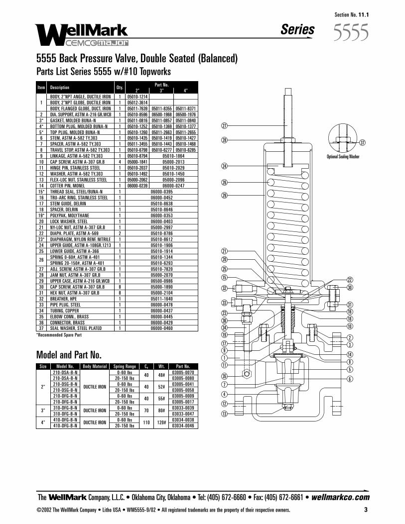
Series
The Company, L.L.C. • Oklahoma City, Oklahoma • Tel: (405) 672-6660 • Fax: (405) 672-6661 • wellmarkco.com©2002 The WellMark Company • Litho USA • WM5555-9/02 • All registered trademarks are the property of their respective owners. 3
5555Section No. 11.1
5555 Back Pressure Valve, Double Seated (Balanced)Parts List Series 5555 w/#10 Topworks
2
9
4
12
1
3
13
23
31
76
511
8
32
27
28
24
26
29
21
20
25
30
10
1618
22
19
17
36
33
35
14
15
34
Optional Sealing Washer
37
Model and Part No.Size Model No. Body Material Spring Range Cv Wt. Part No.
210-DSA-B-N 0-60 lbs 40 48# 03005-0070210-DSA-B-N 20-150 lbs 03005-0080
2" 210-DSG-B-N DUCTILE IRON 0-60 lbs 40 52# 03005-0041210-DSG-B-N 20-150 lbs 03005-0058210-DFG-B-N 0-60 lbs 40 55# 03005-0009210-DFG-B-N 20-150 lbs 03005-0017
3" 310-DFG-B-N DUCTILE IRON 0-60 lbs 70 80# 03033-0039310-DFG-B-N 20-150 lbs 03033-0047
4" 410-DFG-B-N DUCTILE IRON 0-60 lbs 110 120# 03034-0038410-DFG-B-N 20-150 lbs 03034-0046
Item Description Qty. Part No.2" 3" 4"
BODY, 2"NPT ANGLE, DUCTILE IRON 1 05010-12141 BODY, 2"NPT GLOBE, DUCTILE IRON 1 05012-3614
BODY, FLANGED GLOBE, DUCT. IRON 1 05011-7639 05011-8355 05011-83712 DIA. SUPPORT, ASTM A-216 GR.WCB 1 05010-8596 06500-1968 06500-19763* GASKET, MOLDED BUNA-N 1 05011-0816 05011-0857 05011-08404* BOTTOM PLUG, MOLDED BUNA-N 1 05010-1252 05010-1369 05010-13775* TOP PLUG, MOLDED BUNA-N 1 05010-1260 05011-2663 05011-26556 STEM, ASTM A-582 TY.303 1 05010-1435 05010-1419 05010-14277 SPACER, ASTM A-582 TY.303 1 05011-3455 05010-1443 05010-14688 TRAVEL STOP, ASTM A-582 TY.303 1 05010-6798 05010-6277 05010-62859 LINKAGE, ASTM A-582 TY.303 1 05010-8794 05010-1864
10 CAP SCREW, ASTM A-307 GR.B 4 05000-1841 05000-201311 HINGE PIN, STAINLESS STEEL 1 05010-2037 05010-202912 WASHER, ASTM A-582 TY.303 1 05010-1492 05010-145013 FLEX-LOC NUT, STAINLESS STEEL 1 05000-2062 05000-209614 COTTER PIN, MONEL 1 06000-0239 06000-024715* THREAD SEAL, STEEL/BUNA-N 1 06000-039516 TRU-ARC RING, STAINLESS STEEL 1 06000-045217 STEM GUIDE, DELRIN 1 05010-863818 SPACER, DELRIN 1 05010-864619* POLYPAK, MOLYTHANE 1 06000-035320 LOCK WASHER, STEEL 1 06000-040321 NY-LOC NUT, ASTM A-307 GR.B 1 05000-299722 DIAPH. PLATE, ASTM A-569 2 05010-878623* DIAPHRAGM, NYLON RENF. NITRILE 1 05010-861224 UPPER GUIDE, ASTM A-108GR.1213 1 05010-190625 LOWER GUIDE, ASTM A-366 1 05010-1914
26 SPRING 0-60#, ASTM A-401 1 05010-1344SPRING 20-150#, ASTM A-401 1 05010-6293
27 ADJ. SCREW, ASTM A-307 GR.B 1 05010-782028 JAM NUT, ASTM A-307 GR.B 1 05000-207029 UPPER CASE, ASTM A-216 GR.WCB 1 06500-098630 CAP SCREW, ASTM A-307 GR.B 8 05000-189031 HEX NUT, ASTM A-307 GR.B 8 05000-210432 BREATHER, HPE 1 05011-164033 PIPE PLUG, STEEL 1 06000-047834 TUBING, COPPER 1 06000-043735 ELBOW CONN., BRASS 1 06000-044536 CONNECTOR, BRASS 1 06000-042937 SEAL WASHER, STEEL PLATED 1 06000-0460
*Recommended Spare Part

The Company, L.L.C. • Oklahoma City, Oklahoma • Tel: (405) 672-6660 • Fax: (405) 672-6661 • wellmarkco.com
Series
©2009 The WellMark Company, L.L.C. • Litho USA • WM2020-5/09 • All registered trademarks are the property of their respective owners. 1
����Section No. 12.1
2020 Flow Control Choke Valve
ApplicationThis versatile and proven valve is ideal for use in well head control,in gas gathering systems to regulate flow, for CO2 and water orsteam injection systems as well as pressure separators. Suitable forwater, gas and other liquid service.
Features• Choice of Manual, Electric, or Pneumatic Actuation
• Choice of Angle or “Y” Body Style in Carbon or Stainless Steel
• Choice of Tungsten Carbide or Ceramic Disc Material
• Multiple Orifice Sizes for Greater Control
• Low Torque At High Differential Pressure
SpecificationsWorking Pressure . . . . . . . . . . . . . . . . . . . . . . . . To 3600 psi
Body Material . . . . . WCB Carbon Steel or CF8M Stainless Steel
Disc Material . . . . . . . . . . . . . . . . Tungsten Carbide or Ceramic
Dimensional Data
2" NPT(TYP.)WELLMARK 2" NPT (TYP.)
2" ANGLE VALVE 2" "Y" VALVE
2 1/2
4"
16 1/4
3"
6" (MANUAL HANDLE)
11"(MANUAL HANDLE)
8 1/2 9"
14 1/4
11"(MANUAL HANDLE)
14"APPROX.
(MANUAL HANDLE)
1 3/4
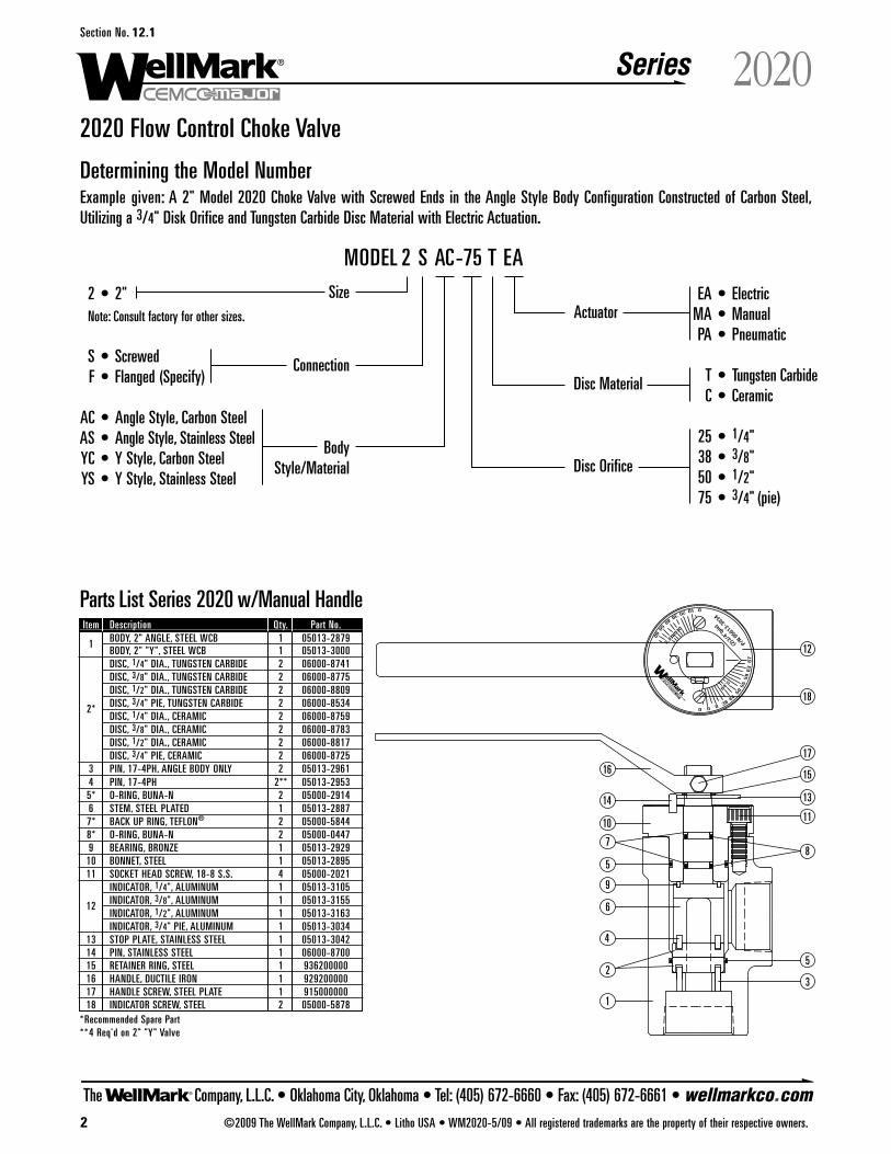
010203040
5060
DEGREE'S
038
44
5055
59
63
67
00
64'S
(2)3
/4"(p
ie)
P/N 0
5013
-303
4
1
23
4
5
6
78
9
10 11
18
1314
151617
5
12
2020 Flow Control Choke Valve
Determining the Model NumberExample given: A 2" Model 2020 Choke Valve with Screwed Ends in the Angle Style Body Configuration Constructed of Carbon Steel,Utilizing a 3/4" Disk Orifice and Tungsten Carbide Disc Material with Electric Actuation.
EA • ElectricMA • ManualPA • Pneumatic
T • Tungsten CarbideC • Ceramic
25 • 1/4"38 • 3/8"50 • 1/2"75 • 3/4" (pie)
2 • 2"Note: Consult factory for other sizes.
S • ScrewedF • Flanged (Specify)
AC • Angle Style, Carbon SteelAS • Angle Style, Stainless SteelYC • Y Style, Carbon SteelYS • Y Style, Stainless Steel
MODEL 2 S AC-75 T EASize
Disc Orifice
Disc Material
Actuator
BodyStyle/Material
Connection
Parts List Series 2020 w/Manual HandleItem Description Qty. Part No.
1 BODY, 2" ANGLE, STEEL WCB 1 05013-2879BODY, 2" "Y", STEEL WCB 1 05013-3000DISC, 1/4" DIA., TUNGSTEN CARBIDE 2 06000-8741DISC, 3/8" DIA., TUNGSTEN CARBIDE 2 06000-8775DISC, 1/2" DIA., TUNGSTEN CARBIDE 2 06000-8809
2* DISC, 3/4" PIE, TUNGSTEN CARBIDE 2 06000-8534DISC, 1/4" DIA., CERAMIC 2 06000-8759DISC, 3/8" DIA., CERAMIC 2 06000-8783DISC, 1/2" DIA., CERAMIC 2 06000-8817DISC, 3/4" PIE, CERAMIC 2 06000-8725
3 PIN, 17-4PH, ANGLE BODY ONLY 2 05013-29614 PIN, 17-4PH 2** 05013-29535* O-RING, BUNA-N 2 05000-29146 STEM, STEEL PLATED 1 05013-28877* BACK UP RING, TEFLON® 2 05000-58448* O-RING, BUNA-N 2 05000-04479 BEARING, BRONZE 1 05013-2929
10 BONNET, STEEL 1 05013-289511 SOCKET HEAD SCREW, 18-8 S.S. 4 05000-2021
INDICATOR, 1/4", ALUMINUM 1 05013-3105
12 INDICATOR, 3/8", ALUMINUM 1 05013-3155INDICATOR, 1/2", ALUMINUM 1 05013-3163INDICATOR, 3/4" PIE, ALUMINUM 1 05013-3034
13 STOP PLATE, STAINLESS STEEL 1 05013-304214 PIN, STAINLESS STEEL 1 06000-870015 RETAINER RING, STEEL 1 93620000016 HANDLE, DUCTILE IRON 1 92920000017 HANDLE SCREW, STEEL PLATE 1 91500000018 INDICATOR SCREW, STEEL 2 05000-5878
*Recommended Spare Part**4 Req'd on 2" "Y" Valve
The Company, L.L.C. • Oklahoma City, Oklahoma • Tel: (405) 672-6660 • Fax: (405) 672-6661 • wellmarkco.com
Series
2 ©2009 The WellMark Company, L.L.C. • Litho USA • WM2020-5/09 • All registered trademarks are the property of their respective owners.
2020Section No. 12.1
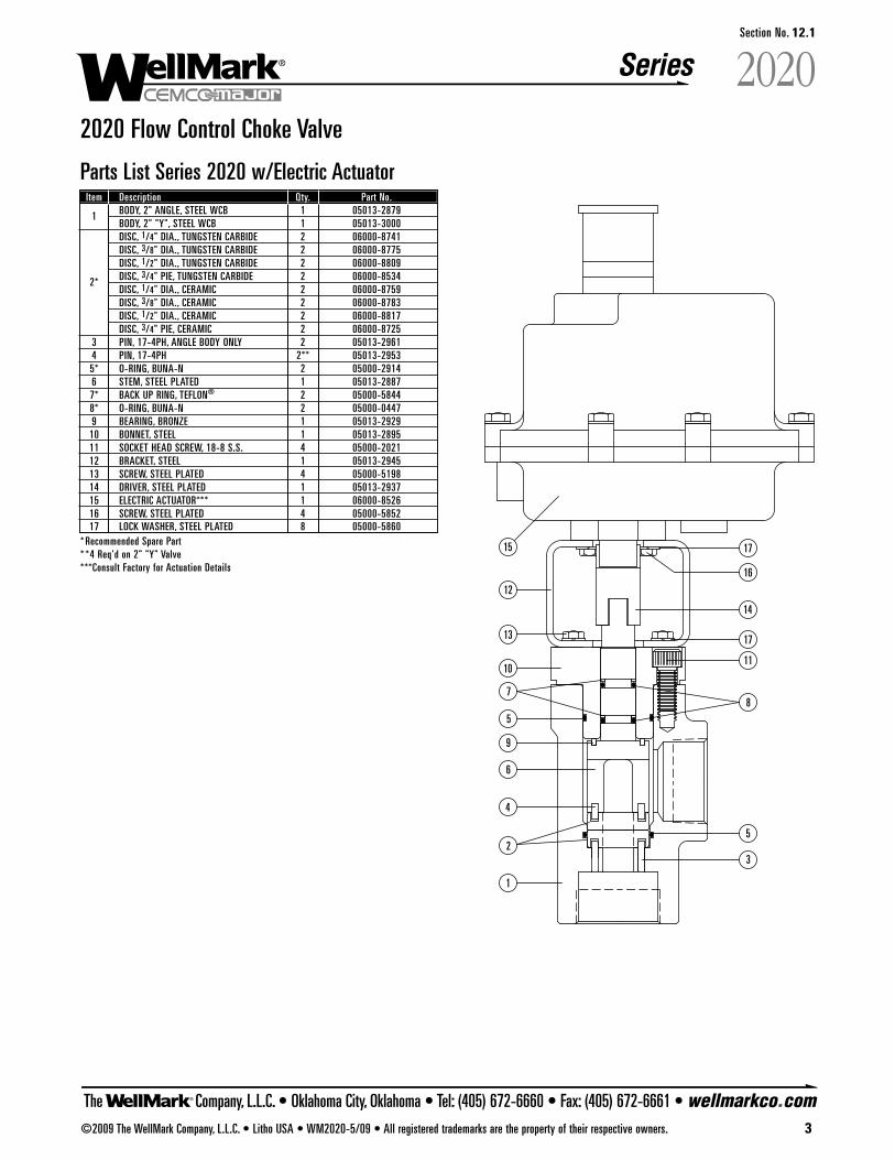
The Company, L.L.C. • Oklahoma City, Oklahoma • Tel: (405) 672-6660 • Fax: (405) 672-6661 • wellmarkco.com
Series
1
23
4
5
6
78
9
1011
13
15
17
5
17
12
14
16
©2009 The WellMark Company, L.L.C. • Litho USA • WM2020-5/09 • All registered trademarks are the property of their respective owners. 3
2020Section No. 12.1
2020 Flow Control Choke Valve
Parts List Series 2020 w/Electric ActuatorItem Description Qty. Part No.
1 BODY, 2" ANGLE, STEEL WCB 1 05013-2879BODY, 2" "Y", STEEL WCB 1 05013-3000DISC, 1/4" DIA., TUNGSTEN CARBIDE 2 06000-8741DISC, 3/8" DIA., TUNGSTEN CARBIDE 2 06000-8775DISC, 1/2" DIA., TUNGSTEN CARBIDE 2 06000-8809
2* DISC, 3/4" PIE, TUNGSTEN CARBIDE 2 06000-8534DISC, 1/4" DIA., CERAMIC 2 06000-8759DISC, 3/8" DIA., CERAMIC 2 06000-8783DISC, 1/2" DIA., CERAMIC 2 06000-8817DISC, 3/4" PIE, CERAMIC 2 06000-8725
3 PIN, 17-4PH, ANGLE BODY ONLY 2 05013-29614 PIN, 17-4PH 2** 05013-29535* O-RING, BUNA-N 2 05000-29146 STEM, STEEL PLATED 1 05013-28877* BACK UP RING, TEFLON® 2 05000-58448* O-RING, BUNA-N 2 05000-04479 BEARING, BRONZE 1 05013-2929
10 BONNET, STEEL 1 05013-289511 SOCKET HEAD SCREW, 18-8 S.S. 4 05000-202112 BRACKET, STEEL 1 05013-294513 SCREW, STEEL PLATED 4 05000-519814 DRIVER, STEEL PLATED 1 05013-293715 ELECTRIC ACTUATOR*** 1 06000-852616 SCREW, STEEL PLATED 4 05000-585217 LOCK WASHER, STEEL PLATED 8 05000-5860
* Recommended Spare Part* *4 Req'd on 2" "Y" Valve***Consult Factory for Actuation Details

The Company, L.L.C. • Oklahoma City, Oklahoma • Tel: (405) 672-6660 • Fax: (405) 672-6661 • wellmarkco.com
Series
AreaOpen
Orifice 25˚ 30˚ 35˚ 40˚ 45˚ 50˚ 55˚ 60˚ 65˚ 70˚ 75˚ 80˚ 85˚ 90˚1/4" 0.0004 0.002 0.0041 0.0068 0.0099 0.0134 0.0172 0.0212 0.0255 0.03 0.0346 0.0394 0.0442 0.0493/8" 0.001 0.004 0.0089 0.0148 0.0218 0.0296 0.0381 0.0473 0.057 0.0672 0.0777 0.0884 0.0994 0.111/2" 0.003 0.009 0.018 0.029 0.041 0.055 0.07 0.086 0.103 0.121 0.139 0.158 0.177 0.196
3/4"(pie) 0.117 0.141 0.1655 0.19 0.2145 0.239 0.2635 0.288 0.312 0.336 0.3605 0.385 0.4095 0.434
0.25
0.2
.23
.24
.21
.22
.18
.19
.16
.17
.13
.14
.11
.12
.08
.09
.06
.07
.03
.04
.01
.02
0.15
0.1
0.05
0Degrees Open Full Open
3/4"(pie)
1/4"
3/8"
1/2"
4 ©2009 The WellMark Company, L.L.C. • Litho USA • WM2020-5/09 • All registered trademarks are the property of their respective owners.
2020Section No. 12.1
For Liquids:
Q = Flow (Barrels/Day)Cv = Flow factorP = Pressure drop
across valveG = Specific gravity
(water=1.0)
For Gas:
Q = Flow (MMSCFD)Cv = Flow factorP1 = Inlet pressure (psia)P2 = Outlet pressure (psia)
P = Pressure drop (P1–P2).When P2 is less than 1/2 P1,use 1/2 P1, for P2 in formula.
G = Specific gravity (air= 1.0)T = Flowing temperature
absolute (˚F + 460)
For Liquids:
Q = 34.3 CvP
G
For Gas:
Q = .0234 CvP(P1+P2)
G TFlow Data
Cv Factor ChartVALVE ORIFICE 1/4" 3/8" 1/2" 3/4" (pie)
Cv FACTOR 2.98 6.84 11.83 31.3
If required flow capacity is known and valve selection is desired,solve for Cv with the formulas below and select appropriate valvefrom Cv Factor Chart above.
Using the Cv factors above for any valve, its approximate flowcapacity can be determined by the formulas at right.
2020 Flow Control Choke Valve
Conversion Chart To Determine Open Area of Disc Orifice to 64th’sOrifice Size
Degrees 1/4" 3/8" 1/2" 3/4" (pie)Open 64th’s Area Open 64th’s Area Open 64th’s Area Open 64th’s Area Open
(Sq. in.) (Sq. in.) (Sq. in.) (Sq. in.)0-20˚ 0 0 0 0 0 0 0 025˚ 2.04 .0004 3.23 .001 5.59 .003 34.93 .11730˚ 4.57 .002 6.46 .004 9.69 .009 38.35 .14135˚ 6.54 .0041 9.63 .0089 13.7 .018 41.55 .165540˚ 8.42 .0068 12.42 .0148 17.39 .029 44.52 .1945˚ 10.16 .0099 15.08 .0218 20.68 .041 47.3 .214550˚ 11.82 .0134 17.57 .0296 23.95 .055 49.93 .23955˚ 13.39 .0172 19.94 .0381 27.02 .07 52.43 .263560˚ 14.87 .0212 21.21 .0473 29.95 .086 54.81 .28865˚ 16.3 .0255 24.38 .057 32.78 .103 57.05 .31270˚ 17.69 .03 26.48 .0672 35.53 .121 59.19 .33675˚ 18.99 .0346 28.47 .0777 38.08 .139 61.32 .360580˚ 20.27 .0394 30.37 .0884 40.59 .158 63.37 .38585˚ 21.47 .0442 32.19 .0994 42.97 .177 65.35 .409590˚ 22.6 .049 33.87 .11 45.21 .196 67.28 .434
Conversion formula for convertingknown open orifice area to 64th’s:
Orifice Open Area Data
Open area of one hole in sq. in.
64th’s = 1282 x Area Open
3.1416
34.3
Q
PG
Cv =
.0234
Q
P (P1 + P2)GT
Cv =
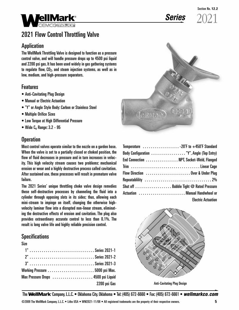
The Company, L.L.C. • Oklahoma City, Oklahoma • Tel: (405) 672-6660 • Fax: (405) 672-6661 • wellmarkco.com
Series
©2009 The WellMark Company, L.L.C. • Litho USA • WM2021-11/08 • All registered trademarks are the property of their respective owners. 5
2021Section No. 12.2
2021 Flow Control Throttling Valve
ApplicationThe WellMark Throttling Valve is designed to function as a pressurecontrol valve, and will handle pressure drops up to 4500 psi liquidand 2200 psi gas. It has been used widely in gas gathering systemsto regulate flow, CO2, and steam injection systems, as well as inlow, medium, and high-pressure separators.
Features• Anti-Cavitating Plug Design
• Manual or Electric Actuation
• "Y" or Angle Style Body: Carbon or Stainless Steel
• Multiple Orifice Sizes
• Low Torque at High Differential Pressure
• Wide Cv Range: 3.2 - 95
OperationMost control valves operate similar to the nozzle on a garden hose.When the valve is set to a partially closed or choked position, theflow of fluid decreases in pressure and in turn increases in veloc-ity. This high velocity stream causes two problems: mechanicalerosion or wear and a highly destructive process called cavitation.After sustained use, these processes will result in premature valvefailure.
The 2021 Series' unique throttling choke valve design remediesthese self-destructive processes by channeling the fluid into acylinder through opposing slots in its sides; thus, allowing eachmini-stream to impinge on itself, changing the otherwise high-velocity laminar flow into a disrupted non-linear stream, eliminat-ing the destructive effects of erosion and cavitation. The plug alsoprovides extraordinary accurate control to less than 0.1%. Theresult is long valve life and highly reliable precision control.
SpecificationsSize
1" . . . . . . . . . . . . . . . . . . . . . . . . . . . . . . . . Series 2021-1
2" . . . . . . . . . . . . . . . . . . . . . . . . . . . . . . . . Series 2021-2
3" . . . . . . . . . . . . . . . . . . . . . . . . . . . . . . . . Series 2021-3
Working Pressure . . . . . . . . . . . . . . . . . . . . . . . 5000 psi Max.
Max Pressure Drops . . . . . . . . . . . . . . . . . . . . 4500 psi Liquid
2200 psi Gas
Temperature . . . . . . . . . . . . . . . . . . -20˚F to +450˚F Standard
Body Configuration . . . . . . . . . . . . . . . . . "Y", Angle (Top Entry)
End Connection . . . . . . . . . . . . . . . . NPT, Socket-Weld, Flanged
Trim . . . . . . . . . . . . . . . . . . . . . . . . . . . . . . . . . . Linear Cage
Flow Direction . . . . . . . . . . . . . . . . . . . . . . Over & Under Plug
Repeatablility . . . . . . . . . . . . . . . . . . . . . . . . . . . . . . . . . 2%
Shut off . . . . . . . . . . . . . . . . . . Bubble Tight @ Rated Pressure
Actuation . . . . . . . . . . . . . . . . . . . . . . . Manual Handwheel or
Electric Actuation
Anti-Cavitating Plug Design
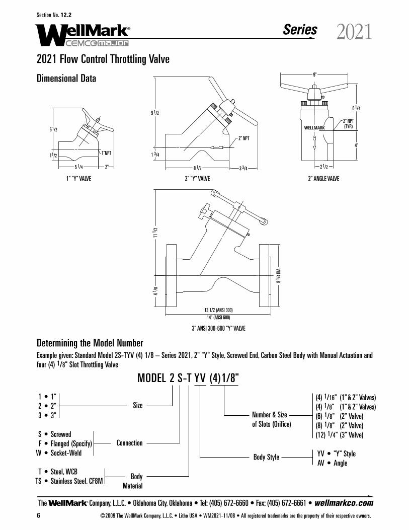
The Company, L.L.C. • Oklahoma City, Oklahoma • Tel: (405) 672-6660 • Fax: (405) 672-6661 • wellmarkco.com
Series
2" NPT(TYP.)WELLMARK
2" ANGLE VALVE2" "Y" VALVE
2" NPT
1"NPT
1" "Y" VALVE
13 1/2 (ANSI 300)14" (ANSI 600)
3" ANSI 300-600 "Y" VALVE
2 1/2
4"
8 1/2
6 1/4
9"
3 3/4
9 1/2
1 3/4
5 1/4 2"
1 1/2
5 1/2
11 1 /
2
8 1 /4 D
IA.
4 1 /8
6 ©2009 The WellMark Company, L.L.C. • Litho USA • WM2021-11/08 • All registered trademarks are the property of their respective owners.
2021Section No. 12.2
2021 Flow Control Throttling Valve
Dimensional Data
Determining the Model NumberExample given: Standard Model 2S-TYV (4) 1/8 – Series 2021, 2" "Y" Style, Screwed End, Carbon Steel Body with Manual Actuation andfour (4) 1/8" Slot Throttling Valve
(4) 1/16" (1" & 2" Valves)(4) 1/8" (1" & 2" Valves)(6) 1/8" (2" Valve)(8) 1/8" (2" Valve)(12) 1/4" (3" Valve)
YV • "Y" StyleAV • Angle
1 • 1"2 • 2"3 • 3"
S • ScrewedF • Flanged (Specify)
W • Socket-Weld
T • Steel, WCBTS • Stainless Steel, CF8M
MODEL 2 S-T YV (4)1/8"
Size
Connection
BodyMaterial
Number & Sizeof Slots (Orifice)
Body Style
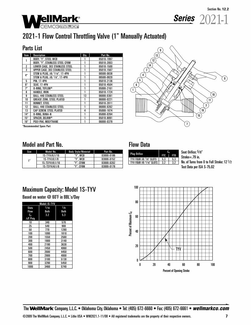
The Company, L.L.C. • Oklahoma City, Oklahoma • Tel: (405) 672-6660 • Fax: (405) 672-6661 • wellmarkco.com
Series
00 20 40 60
Percent of Opening Stroke
Perce
nt of
Max
imum
C v
80 100
20
40
60
80
100
TYV
1
6
5
4
214
12
9
13
8
10
11
3
16
15
7
©2009 The WellMark Company, L.L.C. • Litho USA • WM2021.1-11/08 • All registered trademarks are the property of their respective owners. 7
2021-1Section No. 12.2
2021-1 Flow Control Throttling Valve (1" Manually Actuated)
Parts ListItem Description Qty. Part No.
1 BODY, "Y", STEEL WCB 1 05010-1997BODY, "Y", STAINLESS STEEL CF8M 1 05010-2003
2 LOWER CAGE, 303 STAINLESS STEEL 1 05010-15003 UPPER CAGE, 303 STAINLESS STEEL 1 05010-1567
4* STEM & PLUG, (4) 1/16", 17-4PH 1 06500-0838STEM & PLUG, (4) 1/8", 17-4PH 1 06500-0820
5 PIN, 17-4PH 1 05010-21366* SEAT, 17-4PH 1 05010-45047* O-RING, TEFLON® 1 05000-21618 HANDLE, IRON 1 05010-17249 BALL, 440 STAINLESS STEEL 13 06000-0361
10 GREASE ZERK, STEEL PLATED 1 06000-022111 BONNET, STEEL 1 05010-201112 BALL, 440 STAINLESS STEEL 1 06000-026213 CAP SCREW, STEEL PLATED 4 05000-187414* O-RING, BUNA-N 1 05000-026415* SPACER, DELRIN® 1 05010-809116* POLY-PAK, MOLYTHANE 1 06000-0379
*Recommended Spare Part
Model and Part No.Size Model No. Body Style/Material Part No.
1S-TYV(4)1/16 "Y", WCB 03000-0186
1" 1S-TYV(4)1/8 "Y", WCB 03000-01521S-TSYV(4)1/16 "Y", CF8M 03000-02021S-TSYV(4)1/8 "Y", CF8M 03000-0178
Maximum Capacity: Model 1S-TYVBased on water @ 60˚F in BBL's/Day
Model: IS-TYVSlots 1/16 1/8Flow Both Both
Cv 3.2 5.3�P, Psig
10 340 57025 540 90050 770 1280
100 1090 1810200 1550 2560300 1900 3140400 2190 3630500 2450 4060600 2680 4450700 2900 4800800 3100 5130900 3290 5450
1000 3460 5740
Flow DataCvPlug Orifice FTC FTO
TYV FOUR (4) 1/8" SLOTS 5.3 5.3TYV FOUR (4) 1/16" SLOTS 3.2 3.2
Seat Orifice: 5/8"Stroke=.79 in.No. of Turns from 0 to Full Stroke: 12 1/2
Test Data per ISA S-75.02
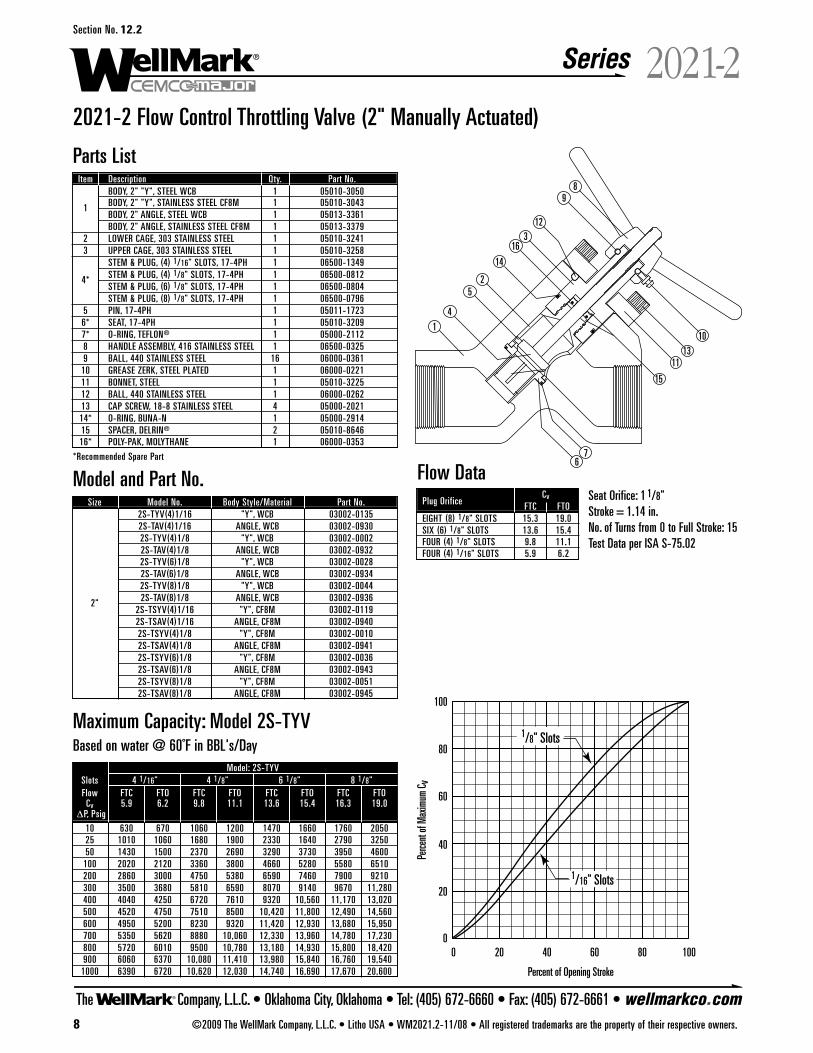
The Company, L.L.C. • Oklahoma City, Oklahoma • Tel: (405) 672-6660 • Fax: (405) 672-6661 • wellmarkco.com
Series
00 20 40 60
Percent of Opening Stroke
Perce
nt of
Max
imum
C v
80 100
20
40
60
80
100
1/16" Slots
1/8" Slots
1
2
3
4
5
67
89
10
11
12
13
14
15
16
8 ©2009 The WellMark Company, L.L.C. • Litho USA • WM2021.2-11/08 • All registered trademarks are the property of their respective owners.
2021-2Section No. 12.2
2021-2 Flow Control Throttling Valve (2" Manually Actuated)
Parts ListItem Description Qty. Part No.
BODY, 2" "Y", STEEL WCB 1 05010-3050
1 BODY, 2" "Y", STAINLESS STEEL CF8M 1 05010-3043BODY, 2" ANGLE, STEEL WCB 1 05013-3361BODY, 2" ANGLE, STAINLESS STEEL CF8M 1 05013-3379
2 LOWER CAGE, 303 STAINLESS STEEL 1 05010-32413 UPPER CAGE, 303 STAINLESS STEEL 1 05010-3258
STEM & PLUG, (4) 1/16" SLOTS, 17-4PH 1 06500-1349
4* STEM & PLUG, (4) 1/8" SLOTS, 17-4PH 1 06500-0812STEM & PLUG, (6) 1/8" SLOTS, 17-4PH 1 06500-0804STEM & PLUG, (8) 1/8" SLOTS, 17-4PH 1 06500-0796
5 PIN, 17-4PH 1 05011-17236* SEAT, 17-4PH 1 05010-32097* O-RING, TEFLON® 1 05000-21128 HANDLE ASSEMBLY, 416 STAINLESS STEEL 1 06500-03259 BALL, 440 STAINLESS STEEL 16 06000-0361
10 GREASE ZERK, STEEL PLATED 1 06000-022111 BONNET, STEEL 1 05010-322512 BALL, 440 STAINLESS STEEL 1 06000-026213 CAP SCREW, 18-8 STAINLESS STEEL 4 05000-202114* O-RING, BUNA-N 1 05000-291415 SPACER, DELRIN® 2 05010-864616* POLY-PAK, MOLYTHANE 1 06000-0353
*Recommended Spare Part
Model and Part No.Size Model No. Body Style/Material Part No.
2S-TYV(4)1/16 "Y", WCB 03002-01352S-TAV(4)1/16 ANGLE, WCB 03002-09302S-TYV(4)1/8 "Y", WCB 03002-00022S-TAV(4)1/8 ANGLE, WCB 03002-09322S-TYV(6)1/8 "Y", WCB 03002-00282S-TAV(6)1/8 ANGLE, WCB 03002-09342S-TYV(8)1/8 "Y", WCB 03002-0044
2" 2S-TAV(8)1/8 ANGLE, WCB 03002-09362S-TSYV(4)1/16 "Y", CF8M 03002-01192S-TSAV(4)1/16 ANGLE, CF8M 03002-09402S-TSYV(4)1/8 "Y", CF8M 03002-00102S-TSAV(4)1/8 ANGLE, CF8M 03002-09412S-TSYV(6)1/8 "Y", CF8M 03002-00362S-TSAV(6)1/8 ANGLE, CF8M 03002-09432S-TSYV(8)1/8 "Y", CF8M 03002-00512S-TSAV(8)1/8 ANGLE, CF8M 03002-0945
Maximum Capacity: Model 2S-TYVBased on water @ 60˚F in BBL's/Day
Flow DataCvPlug Orifice FTC FTO
EIGHT (8) 1/8" SLOTS 15.3 19.0SIX (6) 1/8" SLOTS 13.6 15.4FOUR (4) 1/8" SLOTS 9.8 11.1FOUR (4) 1/16" SLOTS 5.9 6.2
Seat Orifice: 1 1/8"Stroke = 1.14 in.No. of Turns from 0 to Full Stroke: 15Test Data per ISA S-75.02
Model: 2S-TYVSlots 4 1/16" 4 1/8" 6 1/8" 8 1/8"Flow FTC FTO FTC FTO FTC FTO FTC FTO
Cv 5.9 6.2 9.8 11.1 13.6 15.4 16.3 19.0�P, Psig
10 630 670 1060 1200 1470 1660 1760 205025 1010 1060 1680 1900 2330 1640 2790 325050 1430 1500 2370 2690 3290 3730 3950 4600
100 2020 2120 3360 3800 4660 5280 5580 6510200 2860 3000 4750 5380 6590 7460 7900 9210300 3500 3680 5810 6590 8070 9140 9670 11,280400 4040 4250 6720 7610 9320 10,560 11,170 13,020500 4520 4750 7510 8500 10,420 11,800 12,490 14,560600 4950 5200 8230 9320 11,420 12,930 13,680 15,950700 5350 5620 8880 10,060 12,330 13,960 14,780 17,230800 5720 6010 9500 10,780 13,180 14,930 15,800 18,420900 6060 6370 10,080 11,410 13,980 15,840 16,760 19,540
1000 6390 6720 10,620 12,030 14,740 16,690 17,670 20,600
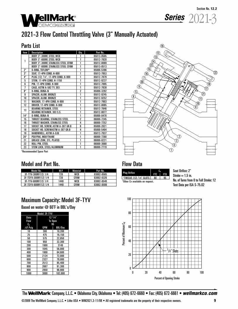
The Company, L.L.C. • Oklahoma City, Oklahoma • Tel: (405) 672-6660 • Fax: (405) 672-6661 • wellmarkco.com
Series
00 20 40 60
Percent of Opening Stroke
Perce
nt of
Max
imum
C v
80 100
20
40
60
80
100
1/4" Slots
23
1
23
4
19
12
14
15
16
720
9
10
5
6
22
18
17
21
11
8
13
©2009 The WellMark Company, L.L.C. • Litho USA • WM2021.3-11/08 • All registered trademarks are the property of their respective owners. 9
������Section No. 12.2
2021-3 Flow Control Throttling Valve (3" Manually Actuated)
Model and Part No.Model No. W.P. Material Part No.
3F-TYV-300RF(12) 1/4 720 WCB 03002-05653F-TSYV-300RF(12) 1/4 720 CF8M 03002-03263F-TYV-600RF(12) 1/4 1440 WCB 03002-0540
3F-TSYV-600RF(12) 1/4 1440 CF8M 03002-0599
Maximum Capacity: Model 3F-TYVBased on water @ 60˚F in BBL's/Day
Model: 3F-TYVSlots 12 1/4"Flow To Open
Cv 95ΔP, Psig GPM BBL/Day
10 300 10,20025 475 16,15050 575 22,850
100 950 32,300200 1900 3140300 1645 56,000400 1900 64,600500 2124 72,000600 2327 79,000700 2513 85,400800 2667 91,300900 2850 96,900
1000 3000 102,000
Flow DataCvPlug Orifice FTC FTO
*TWELVE (12) 1/4" SLOTS 80 95*Other Cv available on request.
Seat Orifice: 2"Stroke = 1.5 in.No. of Turns from 0 to Full Stroke: 12Test Data per ISA S-75.02
Parts ListItem Description Qty. Part No.
BODY 3"-300RF, STEEL WCB 1 05013-0505
1 BODY 3"-600RF, STEEL WCB 1 05012-7820BODY 3"-300RF, STAINLESS STEEL CF8M 1 05012-8069BODY 3"-600RF, STAINLESS STEEL CF8M 1 05013-0513
2* O-RING, TEFLON® 1 05000-53963* SEAT, 17-4PH COND. H-900 1 05012-78534* PLUG (12) 1/4", 17-4PH COND. H-900 1 05012-78795 STEM, 17-4PH COND. H-1150 1 05012-92376 PIN, 17-4PH COND. H-900 1 05012-78957 CAGE, ASTM A-582 TY. 303 1 05012-78388* O-RING, BUNA-N 2 05000-32929 SPACER, ALUM. BRONZE 1 05012-9245
10 SPACER, ALUM. BRONZE 1 05012-925211 WASHER, 17-4PH COND. H-900 1 05012-790312 DRIVER, 17-4PH COND. H-900 1 05012-8085
13 BEARING RETAINER, STEEL 1 05012-7846BEARING RETAINER, 303 S.S. 1 05012-8077
14* O-RING, BUNA-N 1 05000-047015 THRUST BEARING, STAINLESS STEEL 2 06000-724516 THRUST WASHER, STAINLESS STEEL 4 06000-725217 SOCKET HD. SCREW, ASTM A-307 GR.B 8 05000-202118 SOCKET HD. SCREWASTM A-307 GR.B 4 05000-540419 HANDWHELL, ASTM A-536 1 05012-793720* POLYPAK, MOLYTHANE 1 06000-726021 GREASE ZERK, STL. PLATED 1 06000-022122 ROLL PIN, STEEL 1 06000-306823 STEM LOCK, STEEL/ALUMINUM 1 06000-7719
*Recommended Spare Part
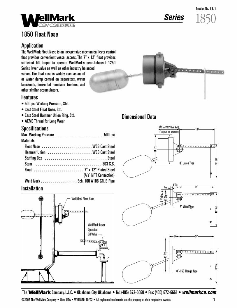
Series
The Company, L.L.C. • Oklahoma City, Oklahoma • Tel: (405) 672-6660 • Fax: (405) 672-6661 • wellmarkco.com©2002 The WellMark Company • Litho USA • WM1850-10/02 • All registered trademarks are the property of their respective owners. 1
1850Section No. 13.1
1850 Float Nose
ApplicationThe WellMark Float Nose is an inexpensive mechanical lever controlthat provides convenient vessel access. The 7" x 12" float providessufficient lift torque to operate WellMark’s near-balanced 1250Series lever valve as well as other industry balancedvalves. The float nose is widely used as an oilor water dump control on separators, waterknockouts, horizontal emulsion treaters, andother similar accumulators.
Features• 500 psi Working Pressure, Std.• Cast Steel Float Nose, Std.• Cast Steel Hammer Union Ring, Std.• ACME Thread for Long Wear
SpecificationsMax. Working Pressure . . . . . . . . . . . . . . . . . . . . . . . . 500 psi Materials
Float Nose . . . . . . . . . . . . . . . . . . . . . . . . . WCB Cast SteelHammer Union . . . . . . . . . . . . . . . . . . . . . . WCB Cast SteelStuffing Box . . . . . . . . . . . . . . . . . . . . . . . . . . . . . . . SteelStem . . . . . . . . . . . . . . . . . . . . . . . . . . . . . . . . . 303 S.S.Float . . . . . . . . . . . . . . . . . . . . . . . . . 7" x 12" Plated Steel
(3/8" NPT Connection)Weld Neck . . . . . . . . . . . . . . . . . . Sch. 100 A106 GR. B Pipe
Installation
8 3/8 (w/8"X5" Weld Neck)
11 3/8 (w/8"X8" Weld Neck)
8" Union Type
6" Weld Type
8"-150 Flange Type
14"
14"
14"4"
11 1 /
2
13 1 /
2
18" S
td.18
" Std.
18" S
td.
3 3/8
6 1 /2 D
ia.6"
Dia.
1/2
Dimensional Data
WellMark Float Nose
WellMark Lever OperatedOil Valve
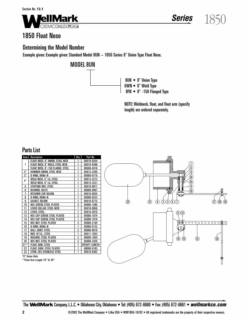
Series
The Company, L.L.C. • Oklahoma City, Oklahoma • Tel: (405) 672-6660 • Fax: (405) 672-6661 • wellmarkco.com2 ©2002 The WellMark Company • Litho USA • WM1850-10/02 • All registered trademarks are the property of their respective owners.
1850Section No. 13.1
1850 Float Nose
Determining the Model NumberExample given: Example given: Standard Model 8UN – 1850 Series 8" Union Type Float Nose.
22 21 4 2 3 5 7
1
69
16
238
10
13
14 15 12 18
11
17 20 19
Parts ListItem Description Qty. Part No.
FLOAT NOSE, 8" UNION, STEEL WCB 1 05010-93541 FLOAT NOSE, 6" WELD, STEEL WCB 1 05010-9388
FLOAT NOSE, 8"-150 FLANGE, STEEL 1 06500-44182* HAMMER UNION, STEEL WCB 1 05013-32053* O-RING, BUNA-N 1 05000-0710
4* WELD NECK, 5" LG. STEEL 1 05013-3213WELD NECK, 8" LG. STEEL 1 05013-3221
5 STUFFING BOX, STEEL 1 05010-08176 BEARING, OILITE 1 06000-00077 RETAINER CUP, DELRIN 1 05010-08258 O-RING, BUNA-N 1 05000-02239 GASKET, DELRIN 1 05010-6715
10 HEX SCREW, STEEL PLATED 3 05000-158511 LEVER COLLAR, STEEL WCB 1 05010-085812 LEVER, STEEL 1 05010-391013 HEX CAP SCREW, STEEL PLATED 2 05000-187414 HEX CAP SCREW, STEEL PLATED 1 05000-191615 HEX NUT, STEEL PLATED 3 05000-210416 O-RING, BUNA-N 1 05000-013217 BALL JOINT, STEEL 2 06000-061918 ROD 18"LG., STEEL 1 05011-105319 WASHER, STEEL PLATED 2 06000-105420 HEX NUT, STEEL PLATED 2 05000-2435
21** FLOAT ARM, STEEL 1 SPECIFY LENGTH22 FLOAT, 500#, STEEL PLATED 1 06000-016323 STEM, 303 STAINLESS STEEL 1 05010-9362
*8" Union Only**Float Arm Length 10" To 30"
8UN • 8" Union Type6WN • 6" Weld Type8FN • 8" -150 Flanged Type
NOTE: Weldneck, float, and float arm (specifylength) are ordered separately.
MODEL 8UN

Series
The Company, L.L.C. • Oklahoma City, Oklahoma • Tel: (405) 672-6660 • Fax: (405) 672-6661 • wellmarkco.com©2002 The WellMark Company • Litho USA • WMLB-10/02 • All registered trademarks are the property of their respective owners. 1
LBSection No. 15.1
LB Line Blinds
ApplicationThe LB Series Line Blinds are used when there is a requirement orneed for two distinctly different fluids to flow through a commonline at different times. The most common use is to keep water andcarbon dioxide (CO2) separate in an injection system. This productis also used in the marine industry, power generating plants, natu-ral gas plants, and liquid storage terminals.
Features • Simple and Easy to Use Gating Design
• Spreader Bolts Come Std. with Lube Fittings
• Teflon® Packing Rings, Positive Seal
• Quick and Safe Flow Transfer Bleed Ports, Std.
• Two External Pins for Positive Alignment
NOTE: All Line Blind spreader flanges come standard with threadinserts (helicoil screw thread inserts). The purpose is to increasethread-life after repeated operation. Their design eliminates erosionof the thread due to friction.
Specifications Size . . . . . . . . . . . . . . . . . . . . . . . . . . . . . . . . . . . . 1" and 2"
Connections . . . . . . . . Flanged (RF or RTJ), Butt-or Socket-Weld
Type . . . . . . . . . . . . . . . . . . . . . . 2-Way In-Line or 3-Way Tee
Working Pressure . . . . . . . . . . . . . . . . . . . . . . . . . to 3600 psi
Materials
Tee Body . . . . . . . . . . . . . . . . . . . . . . . . . . . . . . . . . CF8M
Spreader Flange . . . . . . . . . . . . . . . . . . . . . . CF3M or CF8M
Slotted Flange . . . . . . . . . . . . . . . . . . . . . . . CF3M or CF8M
Spreader Bolts . . . . . . . . . . . . . . . . . . . . . . . . . . B7 or B7M
Gate . . . . . . . . . . . . . . . . . . . . . . . . . . . . . . . . . . 316 S.S.
Packing Ring . . . . . . . . . . . . . . . . . . . . . . . . . . . . . . Teflon®
9 3/8
7 5 /8
8 1 /2 D
ia.
2" Butt-Weld Line Blind
D Di
a.
J
A
1"and 2" Flanged Line Blinds
Dimensional Data 2-Way Line Blinds
DimensionsSize/ANSI A D J1"-1500RF 12 3/4" 5 7/8" 5 3/16"1"-1500RTJ 12 3/4" 5 7/8" 5 3/16"2"-1500RF 15 7/8" 8 1/2" 7 5/8"2"-1500RTJ 16 8 1/2" 7 5/8"
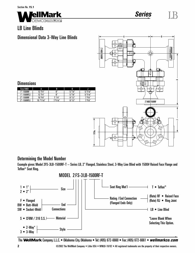
Series
The Company, L.L.C. • Oklahoma City, Oklahoma • Tel: (405) 672-6660 • Fax: (405) 672-6661 • wellmarkco.com2 ©2002 The WellMark Company • Litho USA • WMLB-10/02 • All registered trademarks are the property of their respective owners.
LBSection No. 15.1
LB Line Blinds
Determining the Model NumberExample given: Model 2FS-3LB-1500RF-T – Series LB, 2" Flanged, Stainless Steel, 3-Way Line Blind with 1500# Raised Face Flange andTeflon® Seat Ring.
2"ANSI 1500RF
2"ANSI 1500RFD
Dia.
JA
A B
WA
RN
ING
: P
RES
SU
RE M
UST
BE O
FF BEFO
RE
OP
ERATIN
G TH
IS B
LIND
WARNING: PRESSURE MUSTBE OFF BEFORE
OPERATING THIS BLIND
Wel
lMar
k O
kc.,
Okl
ahom
a
Dimensional Data 3-Way Line Blinds
1 • 1"2 • 2"
F • FlangedBW • Butt-WeldSW • Socket-Weld
S • CF8M / 316 S.S.
• 2-Way*3 • 3-Way
T • Teflon®
(Rate) RF • Raised Face(Rate) RJ • Ring Joint
LB • Line Blind
*Leave Blank WhenSelecting This Option.
MODEL 2 FS-3LB-1500RF-T
Size Seat Ring Mat’l
Rating / End Connection(Flanged Ends Only)End
Connections
Material
Style
DimensionsSize/ANSI A B D J1"-1500RF 12 3/4" 6" 5 7/8" 5 3/16"1"-1500RTJ 12 3/4" 6" 5 7/8" 5 3/16"2"-1500RF 15 5/8" 7 1/4" 8 1/2" 7 5/8"2"-1500RTJ 15 11/16" 7 5/16" 8 1/2" 7 5/8"

Series
The Company, L.L.C. • Oklahoma City, Oklahoma • Tel: (405) 672-6660 • Fax: (405) 672-6661 • wellmarkco.com©2002 The WellMark Company • Litho USA • WMLB-10/02 • All registered trademarks are the property of their respective owners. 3
LBSection No. 15.1
LB Line Blinds
4
5
1 2
3
6
7 8
9
Parts List: 2" Butt-Weld Line BlindItem Description Qty. Part No.
1 FLANGE, SLOTTED, ASTM A-351 GR. CF3M 1 05012-76632 FLANGE, SPREADER, ASTM A-351 GR. CF3M 1 05012-76713 GAGE ASSEMBLY, ASTM A-276 TY.316 1 06500-51084 PACKING RING, TEFLON® 4 05012-77215 SPREADER BOLT, ASTM A-193 GR.B7 3 05012-76896 THREAD INSERT, STAINLESS STEEL 3 06000-72037 LOCATING PIN, STAINLESS STEEL 2 06000-73558 LUBE FITTING, STEEL, PLATED 3 06000-46529 PIPE PLUG, 316 STAINLESS STEEL 2 06000-4702
10* WARNING TAG, ALUMINUM 1 08018-022711* NAME PLATE, ALUMINUM 1 08018-0151
*Not Shown
Model and Part No.Model No. Part No.
2BWS-LB-T 03000-7371
Parts List:1" and 2" ANSI 1500 Flanged Line BlindsItem Description Qty. Part No.
1"-1500RF 1"-1500RTJ 2"-1500RF 2"-1500RTJ1 FLANGE, SLOTTED, ASTM A-351 GR.CF8M 1 05012-8235 05012-7986 05012-8425 05012-80102 FLANGE,SPREADER, ASTM A-351 GR.CF8M 1 05012-9120 05012-7994 05012-8433 05012-80283 GATE, ASTM A-276 TY.316 1 06500-5116 06500-51084 PACKING RING, TEFLON® 4 05012-7754 05012-77215 SPREADER BOLT, ASTM A-193 GR.B7 3 05012-7762 05012-76896 THREAD INSERT, STAINLESS STEEL 3 06000-7294 06000-72037 LOCATING PIN, STAINLESS STEEL 2 06000-7348 06000-73558 LUBE FITTING, STEEL, PLATED 3 06000-4652 06000-46529 PIPE PLUG, 316 STAINLESS STEEL 2 06000-4702 06000-4702
10* WARNING TAG, ALUMINUM 1 08018-0227 08018-022711* NAME PLATE, ALUMINUM 1 08018-0151 08018-0151
*Not Shown
71 5 3 4 8 26
9
Model and Part No.Size/ANSI Model No. W.P. Part No.1"-1500RF 1FS-LB-1500RF-T 3600 PSIG 03000-77961"-1500RTJ 1FS-LB-1500RJ-T 3600 PSIG 03000-74212"-1500RF 2FS-LB-1500RF-T 3600 PSIG 03000-77212"-1500RTJ 2FS-LB-1500RJ-T 3600 PSIG 03000-7439
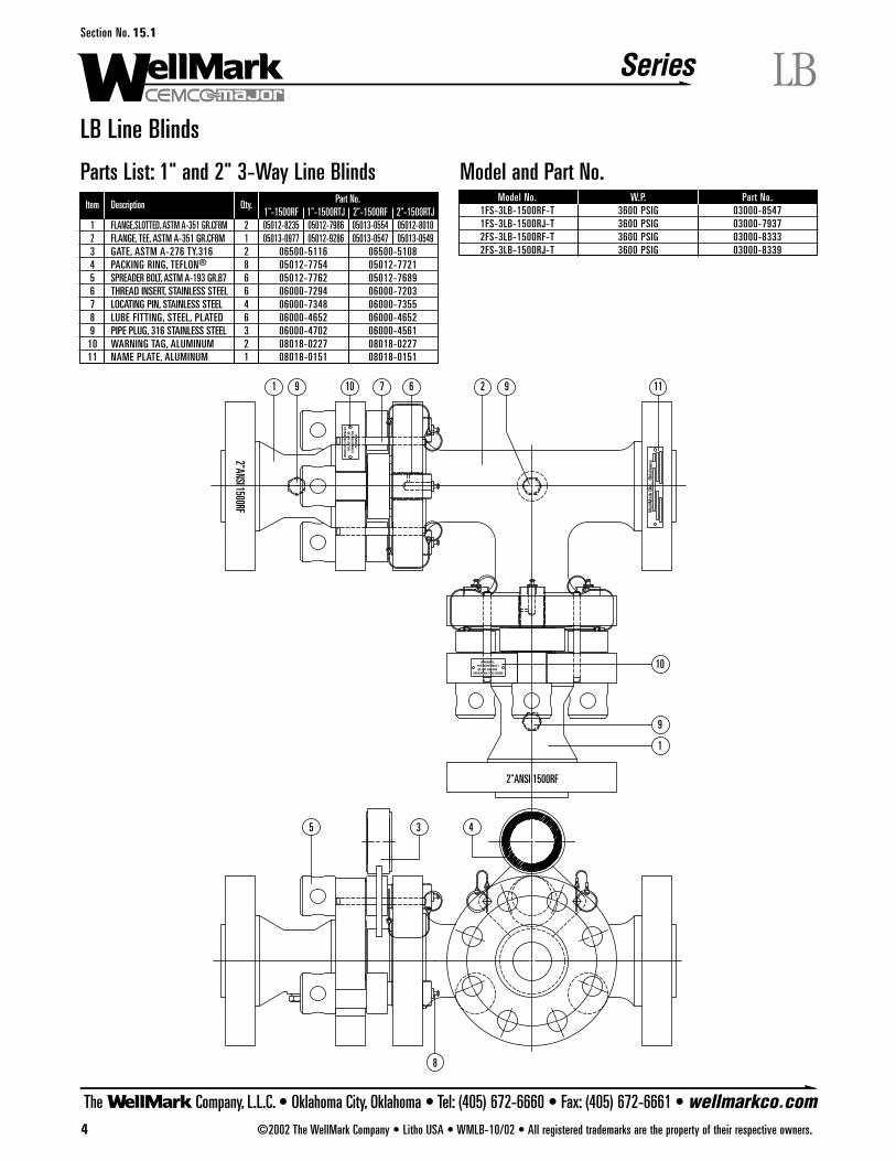
Series
The Company, L.L.C. • Oklahoma City, Oklahoma • Tel: (405) 672-6660 • Fax: (405) 672-6661 • wellmarkco.com4 ©2002 The WellMark Company • Litho USA • WMLB-10/02 • All registered trademarks are the property of their respective owners.
LBSection No. 15.1
LB Line Blinds
Parts List: 1" and 2" 3-Way Line BlindsItem Description Qty. Part No.
1"-1500RF 1"-1500RTJ 2"-1500RF 2"-1500RTJ1 FLANGE,SLOTTED, ASTM A-351 GR.CF8M 2 05012-8235 05012-7986 05013-0554 05012-80102 FLANGE, TEE, ASTM A-351 GR.CF8M 1 05013-0977 05012-9286 05013-0547 05013-05493 GATE, ASTM A-276 TY.316 2 06500-5116 06500-51084 PACKING RING, TEFLON® 8 05012-7754 05012-77215 SPREADER BOLT, ASTM A-193 GR.B7 6 05012-7762 05012-76896 THREAD INSERT, STAINLESS STEEL 6 06000-7294 06000-72037 LOCATING PIN, STAINLESS STEEL 4 06000-7348 06000-73558 LUBE FITTING, STEEL, PLATED 6 06000-4652 06000-46529 PIPE PLUG, 316 STAINLESS STEEL 3 06000-4702 06000-4561
10 WARNING TAG, ALUMINUM 2 08018-0227 08018-022711 NAME PLATE, ALUMINUM 1 08018-0151 08018-0151
2"ANSI 1500RF
2"ANSI 1500RF
1
1
5 3 4
8
10
9 10 7 2 9 11
9
6
Wel
lMar
k O
kc.,
Okl
ahom
a
WA
RN
ING
: P
RES
SU
RE M
UST
BE O
FF BEFO
RE
OP
ERATIN
G TH
IS B
LIND
WARNING: PRESSURE MUSTBE OFF BEFORE
OPERATING THIS BLIND
Model and Part No.Model No. W.P. Part No.
1FS-3LB-1500RF-T 3600 PSIG 03000-85471FS-3LB-1500RJ-T 3600 PSIG 03000-79372FS-3LB-1500RF-T 3600 PSIG 03000-83332FS-3LB-1500RJ-T 3600 PSIG 03000-8339
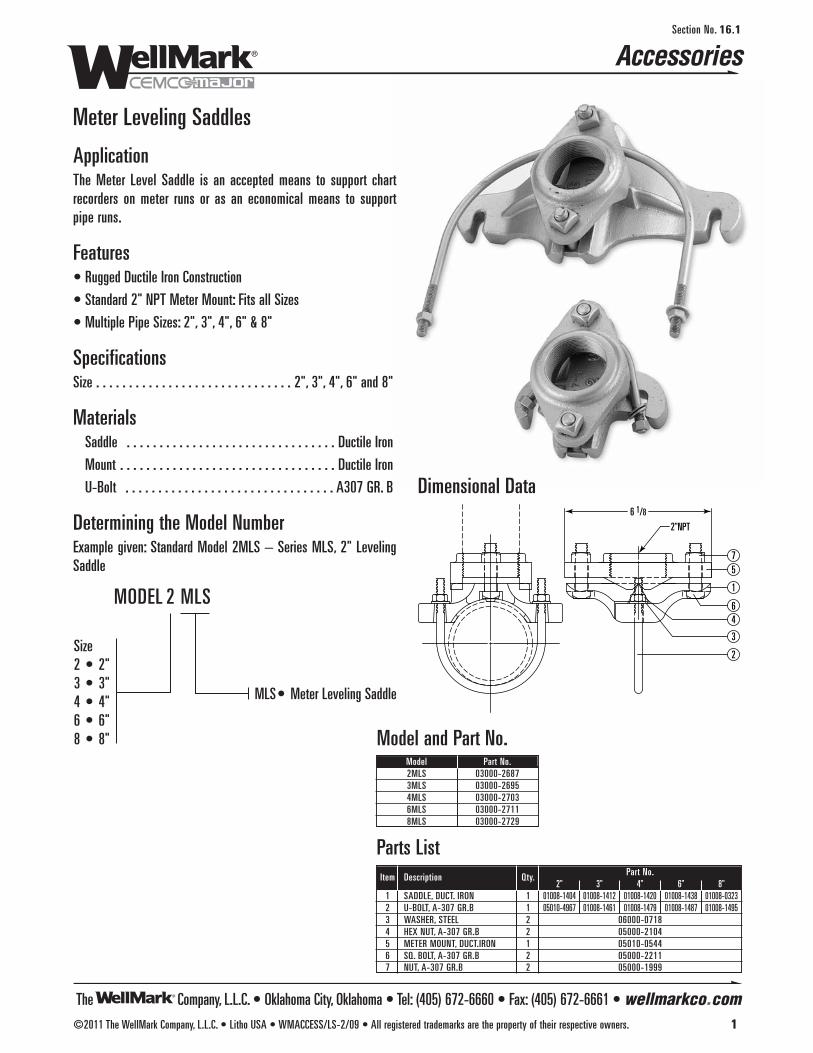
The Company, L.L.C. • Oklahoma City, Oklahoma • Tel: (405) 672-6660 • Fax: (405) 672-6661 • wellmarkco.com
2"NPT
6 1/8
75
1
64
3
2
Accessories
©2011 The WellMark Company, L.L.C. • Litho USA • WMACCESS/LS-2/09 • All registered trademarks are the property of their respective owners. 1
Section No. 16.1
Meter Leveling Saddles
ApplicationThe Meter Level Saddle is an accepted means to support chartrecorders on meter runs or as an economical means to supportpipe runs.
Features• Rugged Ductile Iron Construction
• Standard 2" NPT Meter Mount: Fits all Sizes
• Multiple Pipe Sizes: 2", 3", 4", 6" & 8"
SpecificationsSize . . . . . . . . . . . . . . . . . . . . . . . . . . . . . . 2", 3", 4", 6" and 8"
MaterialsSaddle . . . . . . . . . . . . . . . . . . . . . . . . . . . . . . . . Ductile Iron
Mount . . . . . . . . . . . . . . . . . . . . . . . . . . . . . . . . . Ductile Iron
U-Bolt . . . . . . . . . . . . . . . . . . . . . . . . . . . . . . . . A307 GR. B
Determining the Model NumberExample given: Standard Model 2MLS – Series MLS, 2" LevelingSaddle
MLS• Meter Leveling Saddle
Size2 • 2"3 • 3"4 • 4"6 • 6"8 • 8"
MODEL 2 MLS
Dimensional Data
Model and Part No.Model Part No.2MLS 03000-26873MLS 03000-26954MLS 03000-27036MLS 03000-27118MLS 03000-2729
Parts ListItem Description Qty. Part No.
2" 3" 4" 6" 8"1 SADDLE, DUCT. IRON 1 01008-1404 01008-1412 01008-1420 01008-1438 01008-03232 U-BOLT, A-307 GR.B 1 05010-4967 01008-1461 01008-1479 01008-1487 01008-14953 WASHER, STEEL 2 06000-07184 HEX NUT, A-307 GR.B 2 05000-21045 METER MOUNT, DUCT.IRON 1 05010-05446 SQ. BOLT, A-307 GR.B 2 05000-22117 NUT, A-307 GR.B 2 05000-1999
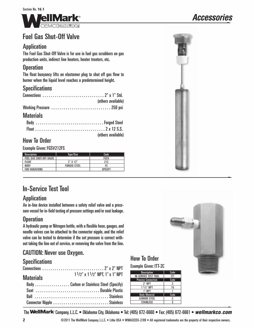
Accessories
2 ©2011 The WellMark Company, L.L.C. • Litho USA • WMACCESS-2/09 • All registered trademarks are the property of their respective owners.
Section No. 16.1
Fuel Gas Shut-Off ValveApplicationThe Fuel Gas Shut-Off Valve is for use in fuel gas scrubbers on gasproduction units, indirect line heaters, heater treaters, etc.
OperationThe float buoyancy lifts an elastomer plug to shut off gas flow toburner when the liquid level reaches a predetermined height.
SpecificationsConnections . . . . . . . . . . . . . . . . . . . . . . . . . . . . . . 2" x 1" Std.
(others available)Working Pressure . . . . . . . . . . . . . . . . . . . . . . . . . . . . . 250 psi
Materials Body . . . . . . . . . . . . . . . . . . . . . . . . . . . . . . . . . Forged SteelFloat . . . . . . . . . . . . . . . . . . . . . . . . . . . . . . . . . . 2 x 12 S.S.
(others available)
In-Service Test ToolApplicationAn in-line device installed between a safety relief valve and a press-sure vessel for in-field testing of pressure settings and/or seat leakage.
OperationA hydraulic pump or Nitrogen bottle, with a flexible hose, gauges, andneedle valves can be attached to the connector nipple, and the reliefvalve can be tested to determine if the set pressure is correct with-out taking the line out of service, or removing the valve from the line.
CAUTION: Never use Oxygen.SpecificationsConnections . . . . . . . . . . . . . . . . . . . . . . . . . . . . . . 2" x 2" NPT
11/2" x 11/2" NPT, 1” x 1” NPTMaterials
Body . . . . . . . . . . . . . . . . . Carbon or Stainless Steel (Specify)Seat . . . . . . . . . . . . . . . . . . . . . . . . . . . . . . . Durable PlasticBall . . . . . . . . . . . . . . . . . . . . . . . . . . . . . . . . . . . . StainlessConnector Nipple . . . . . . . . . . . . . . . . . . . . . . . . . . . Stainless
How To OrderExample Given: FGSV212FS
Description Type/Size CodeFUEL GAS SHUT-OFF VALVE FGSVFLOAT 2" X 12" 212BODY FORGED STEEL FSFOR VARIATIONS SPECIFY
How To OrderExample Given: ITT-2C
Description CodeIN-SERVICE TEST TOOL ITT
Process Connection Code2" NPT 2
1 1/2" NPT 151” NPT 1
Body Material CodeCARBON STEEL C
STAINLESS S
The Company, L.L.C. • Oklahoma City, Oklahoma • Tel: (405) 672-6660 • Fax: (405) 672-6661 • wellmarkco.com
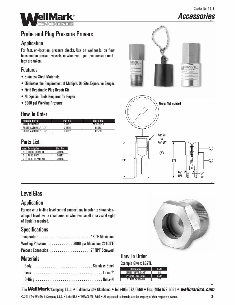
Accessories
©2011 The WellMark Company, L.L.C. • Litho USA • WMACCESS-2/09 • All registered trademarks are the property of their respective owners. 3
Section No. 16.1
2.81 2.75
1/2" NPTor
1/4" NPT
1/2" NPT
1/4" NPT
Gauge Not Included
1
2
3
Probe and Plug Pressure ProversApplicationFor fast, on-location, pressure checks. Use on wellheads, on flowlines and on pressure vessels, or wherever repetitive pressure read-ings are taken.
Features• Stainless Steel Materials
• Eliminates the Requirement of Multiple, On Site, Expensive Gauges
• Field Repairable Plug Repair Kit
• No Special Tools Required for Repair
• 5000 psi Working Pressure
How To OrderPressure Prover Part No. Model No.PLUG ASSEMBLY 30317 M50F25SSPROBE ASSEMBLY (1/2") 30316 F50SSPROBE ASSEMBLY (1/4") 30332 F25SS
Parts ListItem Description Part No.
1 PROBE (COMPLETE) 303162 PLUG BODY 205823 PLUG REPAIR KIT 30318
LevelGlasApplicationFor use with in-line level control connections in order to show visu-al liquid level over a small area, or wherever small area visual sightof liquid is required.
SpecificationsTemperature . . . . . . . . . . . . . . . . . . . . . . . . . . . 180˚F Maximum
Working Pressure . . . . . . . . . . . . . 3000 psi Maximum @100˚F
Process Connection . . . . . . . . . . . . . . . . . . . . . 2" NPT Screwed
MaterialsBody . . . . . . . . . . . . . . . . . . . . . . . . . . . . . . . Stainless Steel
Lens . . . . . . . . . . . . . . . . . . . . . . . . . . . . . . . . . . . . . Lexan®
O-Ring . . . . . . . . . . . . . . . . . . . . . . . . . . . . . . . . . . . Buna-N
How To OrderExample Given: LG2TL
Description CodeSERIES “LEVELGLAS” LGProcess Connection Code2" NPT SCREWED 2T
The Company, L.L.C. • Oklahoma City, Oklahoma • Tel: (405) 672-6660 • Fax: (405) 672-6661 • wellmarkco.com
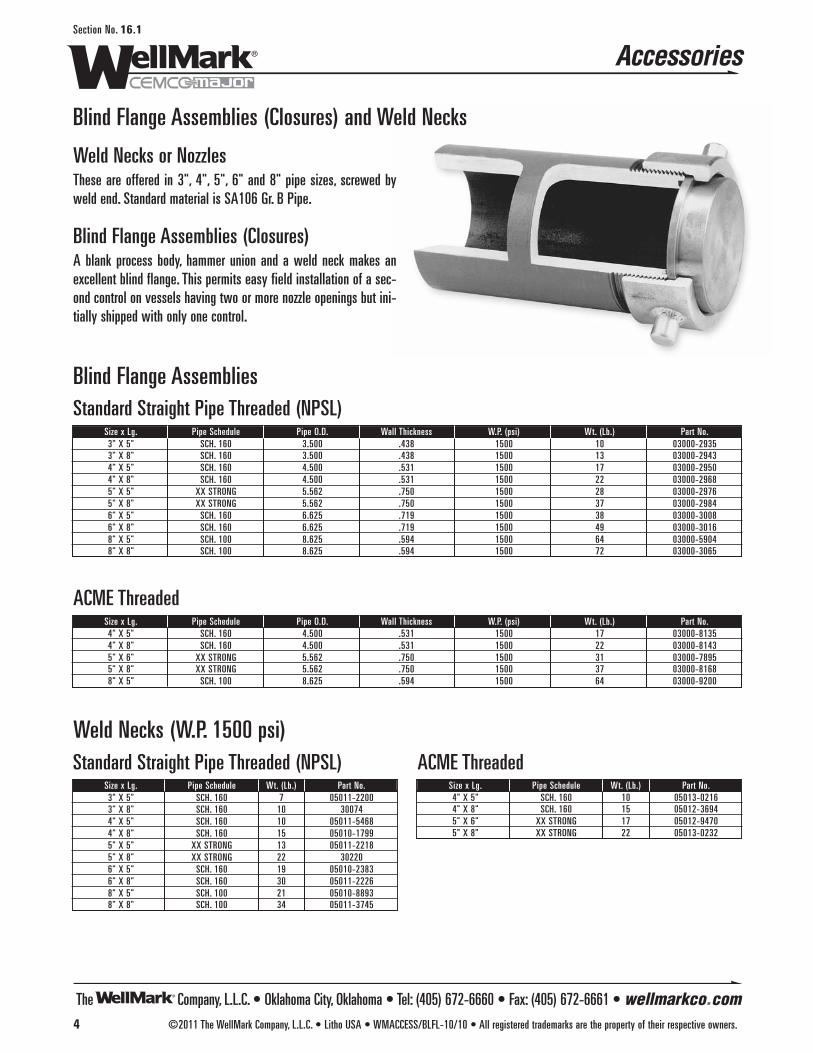
Blind Flange Assemblies (Closures) and Weld Necks
Weld Necks or NozzlesThese are offered in 3", 4", 5", 6" and 8" pipe sizes, screwed byweld end. Standard material is SA106 Gr. B Pipe.
Blind Flange Assemblies (Closures)A blank process body, hammer union and a weld neck makes anexcellent blind flange. This permits easy field installation of a sec-ond control on vessels having two or more nozzle openings but ini-tially shipped with only one control.
Standard Straight Pipe Threaded (NPSL)
Blind Flange Assemblies
Size x Lg. Pipe Schedule Pipe O.D. Wall Thickness W.P. (psi) Wt. (Lb.) Part No.3" X 5" SCH. 160 3.500 .438 1500 10 03000-29353" X 8" SCH. 160 3.500 .438 1500 13 03000-29434" X 5" SCH. 160 4.500 .531 1500 17 03000-29504" X 8" SCH. 160 4.500 .531 1500 22 03000-29685" X 5" XX STRONG 5.562 .750 1500 28 03000-29765" X 8" XX STRONG 5.562 .750 1500 37 03000-29846" X 5" SCH. 160 6.625 .719 1500 38 03000-30086" X 8" SCH. 160 6.625 .719 1500 49 03000-30168" X 5" SCH. 100 8.625 .594 1500 64 03000-59048" X 8" SCH. 100 8.625 .594 1500 72 03000-3065
ACME ThreadedSize x Lg. Pipe Schedule Pipe O.D. Wall Thickness W.P. (psi) Wt. (Lb.) Part No.4" X 5" SCH. 160 4.500 .531 1500 17 03000-81354" X 8" SCH. 160 4.500 .531 1500 22 03000-81435" X 6" XX STRONG 5.562 .750 1500 31 03000-78955" X 8" XX STRONG 5.562 .750 1500 37 03000-81688" X 5" SCH. 100 8.625 .594 1500 64 03000-9200
Standard Straight Pipe Threaded (NPSL)Size x Lg. Pipe Schedule Wt. (Lb.) Part No.3" X 5" SCH. 160 7 05011-22003" X 8" SCH. 160 10 300744" X 5" SCH. 160 10 05011-54684" X 8" SCH. 160 15 05010-17995" X 5" XX STRONG 13 05011-22185" X 8" XX STRONG 22 302206" X 5" SCH. 160 19 05010-23836" X 8" SCH. 160 30 05011-22268" X 5" SCH. 100 21 05010-88938" X 8" SCH. 100 34 05011-3745
ACME ThreadedSize x Lg. Pipe Schedule Wt. (Lb.) Part No.4" X 5" SCH. 160 10 05013-02164" X 8" SCH. 160 15 05012-36945" X 6" XX STRONG 17 05012-94705" X 8" XX STRONG 22 05013-0232
Weld Necks (W.P. 1500 psi)
4 ©2011 The WellMark Company, L.L.C. • Litho USA • WMACCESS/BLFL-10/10 • All registered trademarks are the property of their respective owners.
Section No. 16.1
Accessories
The Company, L.L.C. • Oklahoma City, Oklahoma • Tel: (405) 672-6660 • Fax: (405) 672-6661 • wellmarkco.com
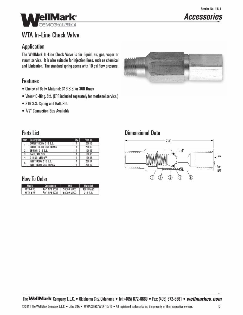
Accessories
©2011 The WellMark Company, L.L.C. • Litho USA • WMACCESS/WTA-10/10 • All registered trademarks are the property of their respective owners. 5
Section No. 16.1
The Company, L.L.C. • Oklahoma City, Oklahoma • Tel: (405) 672-6660 • Fax: (405) 672-6661 • wellmarkco.com
WTA In-Line Check Valve
ApplicationThe WellMark In-Line Check Valve is for liquid, air, gas, vapor orsteam service. It is also suitable for injection lines, such as chemicaland lubrication. The standard spring opens with 10 psi flow pressure.
Features• Choice of Body Material: 316 S.S. or 360 Brass
• Viton® O-Ring, Std. (EPR included separately for methanol service.)
• 316 S.S. Spring and Ball, Std.
• 1/2" Connection Size Available
Dimensional Data
5
Flow
43
27/8"
1/4" NPT
21
Parts ListItem Description Qty. Part No.
1 OUTLET BODY, 316 S.S. 1 20615OUTLET BODY, 360 BRASS 1 20613
2 SPRING, 316 S.S. 1 106063 BALL, 316 S.S. 1 106054 O-RING. VITON® 1 10608
5 INLET BODY, 316 S.S. 1 20614INLET BODY, 360 BRASS 1 20612
How To OrderModel Connection W.P. Material
WTA-676 1/4" NPT FXM 3000# MAX. 360 BRASSWTA-675 1/4" NPT FXM 6000# MAX. 316 S.S.

Series W30 Gauge Valvesand W20 Visual LevelIndicator Assembly Shown
W20 Sight Glass Visual Level Indicator
ApplicationThe Series W20 is a one-piece chamber general purpose, rugged flat glass gauge for mid-range pressure temperature applications.Standard construction includes a solid one-piece chamber machinedfrom carbon steel with carbon steel covers, toughened glass, and plat-ed carbon steel bolts and nuts. All metal parts are rustproofed, and arecessed gasket seat prevents movement, insuring leak-free service.
Features • Available in 9 standard glass sizes
• Constructed with multiple vision slots for longer size requirements
• Toughened molded glass is resistant to thermal and mechanicalshock and made in accordance with BS 3463, DIN 7081
• Quality Assurance Testing: All gauges are hydrostatically testedto 1.5 times the rated pressure at 100˚F (38˚C)
• Materials conform to NACE MR0175 specifications
• Replaces industry standard level gauges
• Female NPT and Union connections available
• Series W20 Sight Glass and W30 Gauge Valve assemblies available
• Repair kit available upon request
Specifications Size . . . . . . . . . . . . . . . . . . . . . . . . . . . . . . . . . . . . 1 through 9
Connections . . . . . . . . . . . . . . . . 1/2" NPT Top-bottom, Standard
Series W20Section No. 14.1
©2014 The WellMark Company • Litho USA • WMW20-1/14 • All registered trademarks are the property of their respective owners. 1
The Company • Oklahoma City, Oklahoma • Tel: (405) 672-6660 • Fax: (405) 672-6661 • wellmarkco.com
Series W20R Shown
Center-to-Center Dimensionfor Assembly Size
(See How To Order)
Series W20R Level Indicator and W30 Gauge Valve Plain Assembly
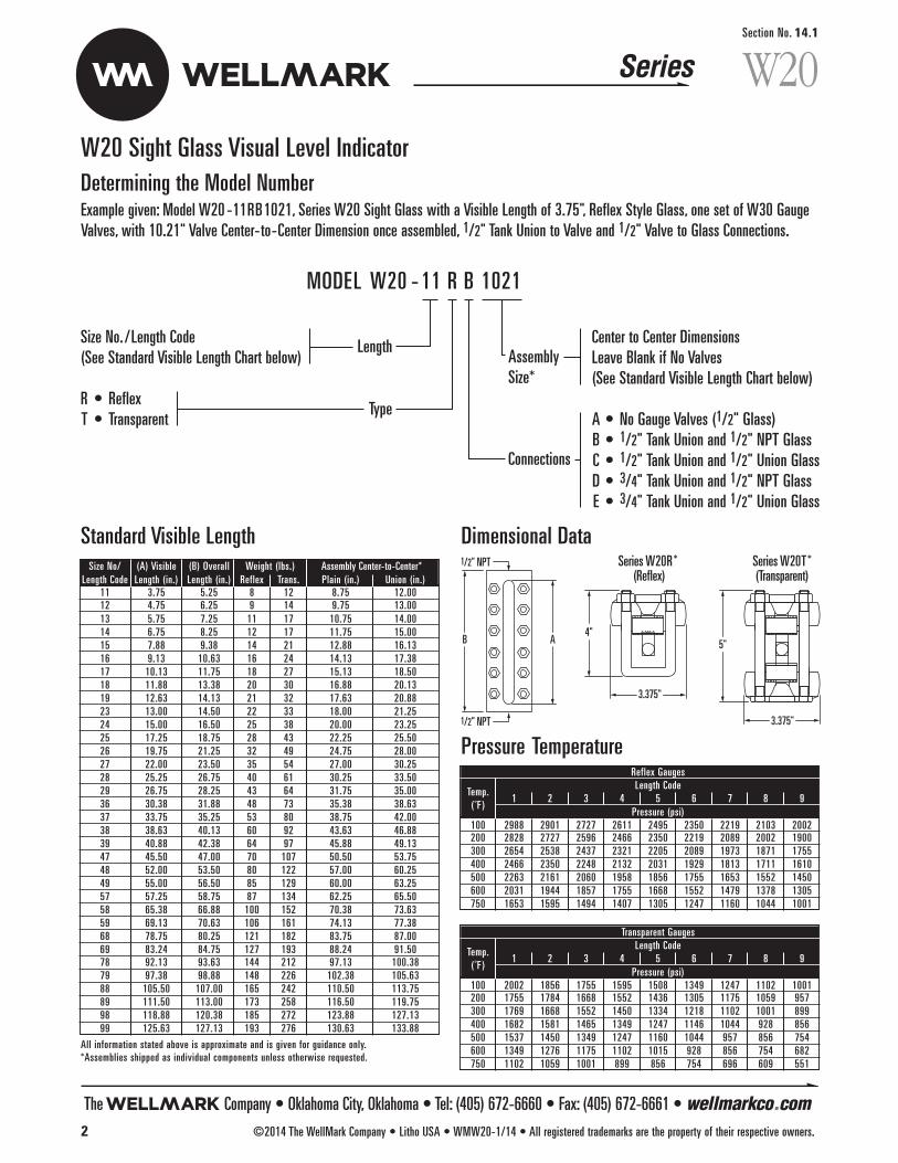
W20 Sight Glass Visual Level Indicator
Series W20Section No. 14.1
Center to Center DimensionsLeave Blank if No Valves(See Standard Visible Length Chart below)
A • No Gauge Valves (1/2" Glass)B • 1/2" Tank Union and 1/2" NPT GlassC • 1/2" Tank Union and 1/2" Union GlassD • 3/4" Tank Union and 1/2" NPT GlassE • 3/4" Tank Union and 1/2" Union Glass
Size No. /Length Code(See Standard Visible Length Chart below)
R • ReflexT • Transparent
MODEL W20 - 11 R B 1021
Determining the Model NumberExample given: Model W20 -11RB1021, Series W20 Sight Glass with a Visible Length of 3.75", Reflex Style Glass, one set of W30 GaugeValves, with 10.21" Valve Center-to-Center Dimension once assembled, 1/2" Tank Union to Valve and 1/2" Valve to Glass Connections.
Length
Type
Connections
AssemblySize*
Dimensional Data
The Company • Oklahoma City, Oklahoma • Tel: (405) 672-6660 • Fax: (405) 672-6661 • wellmarkco.com2 ©2014 The WellMark Company • Litho USA • WMW20-1/14 • All registered trademarks are the property of their respective owners.
Pressure TemperatureReflex Gauges
Temp.Length Code
( ˚F )1 2 3 4 5 6 7 8 9
Pressure (psi)100 2988 2901 2727 2611 2495 2350 2219 2103 2002200 2828 2727 2596 2466 2350 2219 2089 2002 1900300 2654 2538 2437 2321 2205 2089 1973 1871 1755400 2466 2350 2248 2132 2031 1929 1813 1711 1610500 2263 2161 2060 1958 1856 1755 1653 1552 1450600 2031 1944 1857 1755 1668 1552 1479 1378 1305750 1653 1595 1494 1407 1305 1247 1160 1044 1001
Standard Visible Length
Transparent Gauges
Temp.Length Code
( ˚F )1 2 3 4 5 6 7 8 9
Pressure (psi)100 2002 1856 1755 1595 1508 1349 1247 1102 1001200 1755 1784 1668 1552 1436 1305 1175 1059 957300 1769 1668 1552 1450 1334 1218 1102 1001 899400 1682 1581 1465 1349 1247 1146 1044 928 856500 1537 1450 1349 1247 1160 1044 957 856 754600 1349 1276 1175 1102 1015 928 856 754 682750 1102 1059 1001 899 856 754 696 609 551
Series W20R* (Reflex)
Series W20T*(Transparent)
3.375"
3.375"
4"5"
1/2" NPT
B A
1/2" NPTSize No/ (A) Visible (B) Overall Weight (lbs.) Assembly Center-to-Center*Length Code Length (in.) Length (in.) Reflex Trans. Plain (in.) Union (in.)
11 3.75 5.25 8 12 8.75 12.0012 4.75 6.25 9 14 9.75 13.0013 5.75 7.25 11 17 10.75 14.0014 6.75 8.25 12 17 11.75 15.0015 7.88 9.38 14 21 12.88 16.1316 9.13 10.63 16 24 14.13 17.3817 10.13 11.75 18 27 15.13 18.5018 11.88 13.38 20 30 16.88 20.1319 12.63 14.13 21 32 17.63 20.8823 13.00 14.50 22 33 18.00 21.2524 15.00 16.50 25 38 20.00 23.2525 17.25 18.75 28 43 22.25 25.5026 19.75 21.25 32 49 24.75 28.0027 22.00 23.50 35 54 27.00 30.2528 25.25 26.75 40 61 30.25 33.5029 26.75 28.25 43 64 31.75 35.0036 30.38 31.88 48 73 35.38 38.6337 33.75 35.25 53 80 38.75 42.0038 38.63 40.13 60 92 43.63 46.8839 40.88 42.38 64 97 45.88 49.1347 45.50 47.00 70 107 50.50 53.7548 52.00 53.50 80 122 57.00 60.2549 55.00 56.50 85 129 60.00 63.2557 57.25 58.75 87 134 62.25 65.5058 65.38 66.88 100 152 70.38 73.6359 69.13 70.63 106 161 74.13 77.3868 78.75 80.25 121 182 83.75 87.0069 83.24 84.75 127 193 88.24 91.5078 92.13 93.63 144 212 97.13 100.3879 97.38 98.88 148 226 102.38 105.6388 105.50 107.00 165 242 110.50 113.7589 111.50 113.00 173 258 116.50 119.7598 118.88 120.38 185 272 123.88 127.1399 125.63 127.13 193 276 130.63 133.88
All information stated above is approximate and is given for guidance only.*Assemblies shipped as individual components unless otherwise requested.

©2014 The WellMark Company • Litho USA • WMW30-1/14 • All registered trademarks are the property of their respective owners. 3
The Company • Oklahoma City, Oklahoma • Tel: (405) 672-6660 • Fax: (405) 672-6661 • wellmarkco.com
3 9/16" 20S (Plain) • 2 3/4" overall height
20U (Union) 4 13/16" overall height
1 1/2"
1 1/4"
3 11/16" 4 1/4" (Closed)
Glass union option shown
W30 Gauge Valves
ApplicationSeries W30 Gauge valves are recommended for use withWellMark’s Series W20 Visual Level Indicators and are compati-ble with all industry standard, armored flat-glass liquid levelgauges. Plain/Union and Union/Union connections make for easyinstallation and removal.
Features • Equipped with stainless steel ball check upstream of the seat to
shut off flow in case of Level Indicator glass breakage.
• Indicator Union Connection to allow top and bottom connectedIndicators to be rotated to any angle visibilty and allows for easyIndicator removal.
• Gauge Valve and drain connections are offset from the vesselconnection centerline for easier Indicator glass cleaning.
• Materials meet NACE MR0175 specifications.
Specifications Sight Glass Connection . . . . . . . . . . . . . . . . . 1/2" NPT or Union
Tank Connection . . . . . . . . . . . . . . . . . . . . . 1/2" and 3/4" Union
Series W30Section No. 14.2
Determining the Model NumberExample given: Standard Model W30P1, Series W30 Gauge Valve with 1/2" Tank Union and 1/2" Glass Connections.
W30P1 • 1/2" Tank Union and 1/2" NPT GlassW30U1 • 1/2" Tank Union and 1/2" Union GlassW30P2 • 3/4" Tank Union and 1/2" NPT GlassW30U2 • 3/4" Tank Union and 1/2" Union Glass
MODEL W30P1
NOTE: Sold in pairs only.
Connections
Dimensional Data