section one building systems* - freefreeit.free.fr/building design&construction...
TRANSCRIPT

1.1
SECTION ONEBUILDING SYSTEMS*
Jonathan T. RickettsConsulting Engineer
Palm Beach Gardens, Florida
Sociological changes, new technology in industry and commerce, new buildingcodes, other new laws and regulations, inflationary economies of nations, and ad-vances in building technology place an ever-increasing burden on building designersand constructors. They need more and more knowledge and skill to cope with thedemands placed on them.
The public continually demands more complex buildings than in the past. Theymust serve more purposes, last longer, and require less maintenance and repair. Asin the past, they must look attractive. Yet, both building construction and operatingcosts must be kept within acceptable limits or new construction will cease.
To meet this challenge successfully, continual improvements in building designand construction must be made. Building designers and constructors should be alertto these advances and learn how to apply them skillfully.
One advance of note to building design is the adaptation of operations research,or systems design, developed around the middle of the twentieth century and orig-inally applied with noteworthy results to design of machines and electronic equip-ment. In the past, design of a new building was mainly an imitation of the designof an existing building. Innovations were often developed fortuitously and by in-tuition and were rare occurrences. In contrast, systems design encourages innova-tion. It is a precise procedure that guides creativity toward the best decisions. Asa result, it can play a significant role in meeting the challenges posed by increasingbuilding complexity and costs. The basic principles of systems design are presentedin this section.
1.1 PRINCIPLES OF ARCHITECTURE
A building is an assemblage that is firmly attached to the ground and that providestotal or nearly total shelter for machines, processing equipment, performance ofhuman activities, storage of human possessions, or any combination of these.
*Revised and updated from the previous edition by the late Frederick S. Merritt.
1.2 SECTION ONE
Building design is the process of providing all information necessary for con-struction of a building that will meet its owner’s requirements and also satisfy publichealth, welfare, and safety requirements. Architecture is the art and science ofbuilding design. Building construction is the process of assembling materials toform a building.
Building design may be legally executed only by persons deemed competent todo so by the state in which the building is to be constructed. Competency is de-termined on the basis of education, experience, and ability to pass a written test ofdesign skills.
Architects are persons legally permitted to practice architecture. Engineers areexperts in specific scientific disciplines and are legally permitted to design parts ofbuildings; in some cases, complete buildings. In some states, persons licensed asbuilding designers are permitted to design certain types of buildings.
Building construction is generally performed by laborers and craftspeople en-gaged for the purpose by an individual or organization, called a contractor. Thecontractor signs an agreement, or contract, with the building owner under whichthe contractor agrees to construct a specific building on a specified site and theowner agrees to pay for the materials and services provided.
In the design of a building, architects should be guided by the following prin-ciples:
1. The building should be constructed to serve purposes specified by the client.2. The design should be constructable by known techniques and with available
labor and equipment, within an acceptable time.3. The building should be capable of withstanding the elements and normal usage
for a period of time specified by the client.4. Both inside and outside, the building should be visually pleasing.5. No part of the building should pose a hazard to the safety or health of its
occupants under normal usage, and the building should provide for safe evacu-ation or refuge in emergencies.
6. The building should provide the degree of shelter from the elements and ofcontrol of the interior environment—air, temperature, humidity, light, and acous-tics—specified by the client and not less than the minimums required for safetyand health of the occupants.
7. The building should be constructed to minimize adverse impact on the environ-ment.
8. Operation of the building should consume a minimum of energy while permit-ting the structure to serve its purposes.
9. The sum of costs of construction, operation, maintenance, repair, and anticipatedfuture alterations should be kept within the limit specified by the client.
The ultimate objective of design is to provide all the information necessary for theconstruction of a building. This objective is achieved by the production of draw-ings, or plans, showing what is to be constructed, specifications stating what ma-terials and equipment are to be incorporated in the building, and a constructioncontract between the client and a contractor. Designers also should observe con-struction of the building while it is in process. This should be done not only toassist the client in ensuring that the building is being constructed in accordancewith plans and specifications but also to obtain information that will be useful indesign of future buildings.

BUILDING SYSTEMS 1.3
1.2 SYSTEMS DESIGN AND ANALYSIS
Systems design comprises a logical series of steps that leads to the best decisionfor a given set of conditions. The procedure requires:
Analysis of a building as a system.Synthesis, or selection of components, to form a system that meets specific
objectives while subject to constraints, or variables controllable by designers.Appraisal of system performance, including comparisons with alternative sys-
tems.Feedback to analysis and synthesis of information obtained in system evalua-
tion, to improve the design.The prime advantage of the procedure is that, through comparisons of alterna-
tives and data feedback to the design process, systems design converges on anoptimum, or best, system for the given conditions. Another advantage is that theprocedure enables designers to clarify the requirements for the building being de-signed. Still another advantage is that the procedure provides a common basis ofunderstanding and promotes cooperation between the specialists in various aspectsof building design.
For a building to be treated as a system, as required in systems design, it isnecessary to know what a system is and what its basic characteristic are.
A system is an assemblage formed to satisfy specific objectives and subject toconstraints and restrictions and consisting of two or more components that areinterrelated and compatible, each component being essential to the required per-formance of the system.
Because the components are required to be interrelated, operation, or even themere existence, of one component affects in some way the performance of othercomponents. Also, the required performance of the system as a whole, as well asthe constraints on the system, imposes restrictions on each component.
A building meets the preceding requirements. By definition, it is an assemblage(Art. 1.1). It is constructed to serve specific purposes. It is subject to constraintswhile doing so, inasmuch as designers can control properties of the system byselection of components (Art. 1.9). Building components, such as walls, floors,roofs, windows, and doors, are interrelated and compatible with each other. Theexistence of any of thee components affects to some extent the performance of theothers. And the required performance of the building as a whole imposes restrictionson the components. Consequently, a building has the basic characteristics of asystem, and systems-design procedures should be applicable to it.
Systems Analysis. A group of components of a system may also be a system.Such a group is called a subsystem. It, too, may be designed as a system, but itsgoal must be to assist the system of which it is a component to meet its objectives.Similarly, a group of components of a subsystem may also be a system. That groupis called a subsubsystem.
For brevity, the major subsystems of a building are referred to as systems in thisbook.
In a complex system, such as a building, subsystems and other components maybe combined in a variety of ways to form different systems. For the purposes ofbuilding design, the major systems are usually defined in accordance with the con-struction trades that will assemble them, for example, structural framing, plumbing,electrical systems, and heating, ventilation, and air conditioning.
In systems analysis, a system is resolved into its basic components. Subsystemsare determined. Then, the system is investigated to determine the nature, interaction,

1.4 SECTION ONE
and performance of the system as a whole. The investigation should answer suchquestions as:
What does each component (or subsystem) do?What does the component do it to?How does the component serve its function?What else does the component do?Why does the component do the things it does?What must the component really do?Can it be eliminated because it is not essential or because another componentcan assume its tasks?
See also Art. 1.8.
1.3 TRADITIONAL DESIGN PROCEDURES
Systems design of buildings requires a different approach to design and constructionthan that used in traditional design (Art. 1.9). Because traditional design and con-struction procedures are still widely used, however, it is desirable to incorporate asmuch of those procedures in systems design as is feasible without destroying itseffectiveness. This will make the transition from traditional design to systems de-sign easier. Also, those trained in systems design of buildings will then be capableof practicing in traditional ways, if necessary.
There are several variations of traditional design and construction. These aredescribed throughout this book. For the purpose of illustrating how they may bemodified for systems design, however, one widely used variation, which will becalled basic traditional design and construction, is described in the following andin Art. 1.4.
In the basic traditional design procedure, design usually starts when a clientrecognizes the need for and economic feasibility of a building and engages anarchitect, a professional with a broad background in building design. The architect,in turn, engages consulting engineers and other consultants.
For most buildings, structural, mechanical, and electrical consulting engineersare required. A structural engineer is a specialist trained in the application of sci-entific principles to the design of load-bearing walls, floors, roofs, foundations, andskeleton framing needed for the support of buildings and building components. Amechanical engineer is a specialist trained in the application of scientific principlesto the design of plumbing, elevators, escalators, horizontal walkways, dumbwaiters,conveyors, installed machinery, and heating, ventilation, and air conditioning. Anelectrical engineer is a specialist trained in the application of scientific principlesto the design of electric circuits, electric controls and safety devices, electric motorsand generators, electric lighting, and other electric equipment.
For buildings on a large site, the architect may engage a landscape architect asa consultant. For a concert hall, an acoustics consultant may be engaged; for ahospital, a hospital specialist; for a school, a school specialist.
The architect does the overall planning of the building and incorporates theoutput of the consultants into the contract documents. The architect determines whatinternal and external spaces the client needs, the sizes of these spaces, their relative

BUILDING SYSTEMS 1.5
locations, and their interconnections. The results of this planning are shown in floorplans, which also diagram the internal flow, or circulation, of people and supplies.Major responsibilities of the architect are enhancement of the appearance insideand outside of the building and keeping adverse environmental impact of the struc-ture to a minimum. The exterior of the building is shown in drawings, called ele-vations. The location and orientation of the building is shown in a site plan. Thearchitect also prepares the specifications for the building. These describe in detailthe materials and equipment to be installed in the structure. In addition, the archi-tect, usually with the aid of an attorney engaged by the client, prepares the con-struction contract.
The basic traditional design procedure is executed in several stages. In the firststage, the architect develops a program, or list of the client’s requirements. In thenext stage, the schematic or conceptual phase, the architect translates requirementsinto spaces, relates the spaces and makes sketches, called schematics, to illustratethe concepts. When sufficient information is obtained on the size and general con-struction of the building, a rough estimate is made of construction cost. If this costdoes not exceed the cost budgeted by the client for construction, the next stage,design development, proceeds. In this stage, the architect and consultants work outmore details and show the results in preliminary construction drawings and outlinespecifications. A preliminary cost estimate utilizing the greater amount of infor-mation on the building now available is then prepared. If this cost does not exceedthe client’s budget, the final stage, the contract documents phase, starts. It cul-minates in production of working, or construction, drawings and specifications,which are incorporated in the contract between the client and a builder and thereforebecome legal documents. Before the documents are completed, however, a finalcost estimate is prepared. If the cost exceeds the client’s budget, the design isrevised to achieve the necessary cost reduction.
In the traditional design procedure, after the estimated cost is brought within thebudget and the client has approved the contract documents, the architect helps theowner in obtaining bids from contractors or in negotiating a construction price witha qualified contractor. For private work, construction not performed for a govern-mental agency, the owner generally awards the construction contract to a contractor,called a general contractor. Assigned the responsibility for construction of thebuilding, this contractor may perform some, all, or none of the work. Usually, muchof the work is let out to specialists, called subcontractors. For public work, theremay be a legal requirement that bids be taken and the contract awarded to thelowest responsible bidder. Sometimes also, separate contracts have to be awardedfor the major specialists, such as mechanical and electrical trades, and to a generalcontractor, who is assigned responsibility for coordinating the work of the tradesand performance of the work. (See also Art. 1.4.)
Building design should provide for both normal and emergency conditions. Thelatter includes fire, explosion, power cutoffs, hurricanes, and earthquakes. The de-sign should include access and facilities for disabled persons.
1.4 TRADITIONAL CONSTRUCTIONPROCEDURES
As mentioned in Art. 1.3, construction under the traditional construction procedureis performed by contractors. While they would like to satisfy the owner and the

1.6 SECTION ONE
building designers, contractors have the main objective of making a profit. Hence,their initial task is to prepare a bid price based on an accurate estimate of construc-tion costs. This requires development of a concept for performance of the workand a construction time schedule. After a contract has been awarded, contractorsmust furnish and pay for all materials, equipment, power, labor, and supervisionrequired for construction. The owner compensates the contractors for constructioncosts and services.
A general contractor assumes overall responsibility for construction of a build-ing. The contractor engages subcontractors who take responsibility for the workof the various trades required for construction. For example, a plumbing contractorinstalls the plumbing, an electrical contractor installs the electrical system, a steelerector structural steel, and an elevator contractor installs elevators. Their contractsare with the general contractor, and they are paid by the general contractor.
Sometimes, in addition to a general contractor, the owners contracts separatelywith specialty contractors, such as electrical and mechanical contractors, who per-form a substantial amount of the work required for a building. Such contractors arecalled prime contractors. Their work is scheduled and coordinated by the generalcontractor, but they are paid directly by the owner.
Sometimes also, the owner may use the design-build method and award a con-tract to an organization for both the design and construction of a building. Suchorganizations are called design-build contractors. One variation of this type ofcontract is employed by developers of groups of one-family homes or low-riseapartment buildings. The homebuilder designs and constructs the dwellings, butthe design is substantially completed before owners purchase the homes.
Administration of the construction procedure often is difficult. Consequently,some owners seek assistance from an expert, called a professional constructionmanager, with extensive construction experience, who receives a fee. The construc-tion manager negotiates with general contractors and helps select one to constructthe building. Managers usually also supervise selection of subcontractors. Duringconstruction, they help control costs, expedite equipment and material deliveries,and keep the work on schedule (see Art. 17.9). In some cases, instead, the ownermay prefer to engage a construction program manager, to assist in administratingboth design and construction.
Construction contractors employ labor that may or may not be unionized. Un-ionized craftspeople are members of unions that are organized by constructiontrades, such as carpenter, plumber, and electrician unions. Union members willperform only the work assigned to their trade. On the job, groups of workers aresupervised by crew supervisors, all of whom report to a superintendent.
During construction, all work should be inspected. For this purpose, the owner,often through the architect and consultants, engages inspectors. The field inspectorsmay be placed under the control of an owner’s representative, who may be titledclerk of the works, architect’s superintendent, engineer’s superintendent, or residentengineer. The inspectors have the responsibility of ensuring that construction meetsthe requirements of the contract documents and is performed under safe conditions.Such inspections may be made at frequent intervals.
In addition, inspections also are made by representatives of one or more gov-ernmental agencies. They have the responsibility of ensuring that construction meetslegal requirements and have little or no concern with detailed conformance withthe contract documents. Such legal inspections are made periodically or at the endof certain stages of construction. One agency that will make frequent inspectionsis the local or state building department, whichever has jurisdiction. The purposeof these inspections is to ensure conformance with the local or state building code.

BUILDING SYSTEMS 1.7
During construction, standards, regulations, and procedures of the OccupationalSafety and Health Administration should be observed. These are given in detail in‘‘Construction Industry. OSHA Safety and Health Standards (29CFR1926/1910),’’Government Printing Office, Washington, DC 20402.
Following is a description of the basic traditional construction procedure for amultistory building:
After the award of a construction contract to a general contractor, the ownermay ask the contractor to start a portion of the work before signing of the contractby giving the contractor a letter of intent or after signing of the contract by issuinga written notice to proceed. The contractor then obtains construction permits, asrequired, from governmental agencies, such as the local building, water, sewer, andhighway departments.
The general contractor plans and schedules construction operations in detail andmobilizes equipment and personnel for the project. Subcontractors are notified ofthe contract award and issued letters of intent or awarded subcontracts, then aregiven, at appropriate times, notices to proceed.
Before construction starts, the general contractor orders a survey to be made ofadjacent structures and terrain, both for the record and to become knowledgeableof local conditions. A survey is then made to lay out construction.
Field offices for the contractor are erected on or near the site. If desirable forsafety reasons to protect passersby, the contractor erects a fence around the site andan overhead protective cover, called a bridge. Structures required to be removedfrom the site are demolished and the debris is carted away.
Next, the site is prepared to receive the building. This work may involve gradingthe top surface to bring it to the proper elevations, excavating to required depthsfor basement and foundations, and shifting of utility piping. For deep excavations,earth sides are braced and the bottom is drained.
Major construction starts with the placement of foundations, on which the build-ing rests. This is followed by the erection of load-bearing walls and structuralframing. Depending on the height of the building, ladders, stairs, or elevators maybe installed to enable construction personnel to travel from floor to floor and even-tually to the roof. Also, hoists may be installed to lift materials to upper levels. Ifneeded, temporary flooring may be placed for use of personnel.
As the building rises, pipes, ducts, and electric conduit and wiring are installed.Then, permanent floors, exterior walls, and windows are constructed. At the appro-priate time, permanent elevators are installed. If required, fireproofing is placed forsteel framing. Next, fixed partitions are built and the roof and its covering, orroofing, are put in place.
Finishing operations follow. These include installation of the following: ceilings;tile; wallboard; wall paneling; plumbing fixtures; heating furnaces; air-conditioningequipment; heating and cooling devices for rooms; escalators; floor coverings; win-dow glass; movable partitions; doors; finishing hardware; electrical equipment andapparatus, including lighting fixtures, switches, outlets, transformers, and controls;and other items called for in the drawings and specifications. Field offices, fences,bridges, and other temporary construction must be removed from the site. Utilities,such as gas, electricity, and water, are hooked up to the building. The site is land-scaped and paved. Finally, the building interior is painted and cleaned.
The owner’s representatives then give the building a final inspection. If they findthat the structure conforms with the contract documents, the owner accepts theproject and gives the general contractor final payment on issuance by the buildingdepartment of a certificate of occupancy, which indicates that the completed build-ing meets building-code requirements.

1.8 SECTION ONE
1.5 ROLE OF THE CLIENT IN DESIGN ANDCONSTRUCTION
Article 1.4 points out that administration of building construction is difficult, as aresult of which some clients, or owners, engage a construction manager or con-struction program manager to act as the owner’s authorizing agent and projectoverseer. The reasons for the complexity of construction administration can be seenfrom an examination of the owner’s role before and during construction.
After the owner recognizes the need for a new building, the owner establishesproject goals and determines the economic feasibility of the project. If it appearsto be feasible, the owner develops a building program (list of requirements), budget,and time schedule for construction. Next, preliminary arrangements are made tofinance construction. Then, the owner selects a construction program manager oran architect for design of the building. Later, a construction manager may be cho-sen, if desired.
The architect may seek from the owner approval of the various consultants thatwill be needed for design. If a site for the building has not been obtained at thisstage, the architect can assist in site selection. When a suitable site has been found,the owner purchases it and arranges for surveys and subsurface explorations toprovide information for locating the building, access, foundation design and con-struction, and landscaping. It is advisable at this stage for the owner to start de-veloping harmonious relations with the community in which the building will beerected.
During design, the owner assists with critical design decisions; approves sche-matic drawings, rough cost estimates, preliminary drawings, outline specifications,preliminary cost estimates, contract documents, and final cost estimate; pays de-signers’ fees in installments as design progresses; and obtains a construction loan.Then, the owner awards the general contract for construction and orders construc-tion to start. Also, the owner takes out liability, property, and other desirable in-surance.
At the start of construction, the owner arranges for construction permits. Asconstruction proceeds, the owner’s representatives inspect the work to ensure com-pliance with the contract documents. Also, the owner pays contractors in accordancewith the terms of the contract. Finally, the owner approves and accepts the com-pleted project.
One variation of the preceding procedure is useful when time available for con-struction is short. It is called phase, or fast-track, construction. In this variation,the owner engages a construction manager and a general contractor before designhas been completed, to get an early start on construction. Work then proceeds onsome parts of the building while other parts are still being designed. For example,excavation and foundation construction are carried out while design of the structuralframing is being finished. The structural framing is erected, while heating, venti-lation, and air-conditioning, electrical, plumbing, wall, and finishing details arebeing developed. For tall buildings, the lower portion can be constructed while theupper part is still being designed. For large, low-rise buildings, one section can bebuilt while another is under design.
1.6 BUILDING COSTS
Construction cost of a building usually is a dominant design concern. One reasonis that if construction cost exceeds the owner’s budget, the owner may cancel the

BUILDING SYSTEMS 1.9
project. Another reason is that costs, such as property taxes and insurance, thatoccur after completion of the building often are proportional to the initial cost.Hence, owners usually try to keep that cost low. Designing a building to minimizeconstruction cost, however, may not be in the owner’s best interests. There aremany other costs that the owner incurs during the anticipated life of the buildingthat should be taken into account.
Before construction of a building starts, the owner generally has to make asizable investment in the project. The major portion of this expenditure usuallygoes for purchase of the site and building design. Remaining preconstruction costsinclude those for feasibility studies, site selection and evaluation, surveys, and pro-gram definition.
The major portion of the construction cost is the sum of the payments to thegeneral contractor and prime contractors. Remaining construction costs usually con-sist of interest on the construction loan, permit fees, and costs of materials, equip-ment, and labor not covered by the construction contracts.
The initial cost to the owner is the sum of preconstruction, construction, andoccupancy costs. The latter covers costs of moving possessions into the buildingand start-up of utility services, such as water, gas, electricity, and telephone.
After the building is occupied, the owner incurs costs for operation and main-tenance of the buildings. Such costs are a consequence of decisions made duringbuilding design.
Often, preconstruction costs are permitted to be high so that initial costs can bekept low. For example, operating the building may be expensive because the designmakes artificial lighting necessary when daylight could have been made availableor because extra heating and air conditioning are necessary because of inadequateinsulation of walls and roof. As another example, maintenance may be expensivebecause of the difficulty of changing electric lamps or because cleaning the buildingis time-consuming and laborious. In addition, frequent repairs may be needed be-cause of poor choice of materials during design. Hence, operation and maintenancecosts over a specific period of time, say 10 or 20 years, should be taken into accountin optimizing the design of a building.
Life-cycle cost is the sum of initial, operating, and maintenance costs. Generally,it is life-cycle cost that should be minimized in building design rather than con-struction cost. This would enable the owner to receive the greatest return on theinvestment in the building. ASTM has promulgated a standard method for calcu-lating life-cycle costs of buildings, E917, Practice for Measuring Life-Cycle Costsof Buildings and Building Systems, as well as a computer program and user’s guideto improve accuracy and speed of calculation.
Nevertheless, a client usually establishes a construction budget independent oflife-cycle cost. This often is necessary because the client does not have adequatecapital for an optimum building and places too low a limit on construction cost.The client hopes to have sufficient capital later to pay for the higher operating andmaintenance costs or for replacement of undesirable building materials and installedequipment. Sometimes, the client establishes a low construction budget because theclient’s goal is a quick profit on early sale of the building, in which case the clienthas little or no concern with future high operating and maintenance costs for thebuilding. For these reasons, construction cost frequently is a dominant concern indesign.
1.7 MAJOR BUILDING SYSTEMS
The simplest building system consists of only two components. One component isa floor, a flat, horizontal surface on which human activities can take place. The

1.10 SECTION ONE
FIGURE 1.1 Vertical section through a one-story building with basement shows locationof some major components. (Reprinted with permission from F. S. Merritt and J. Ambrose,‘‘Building Engineering and Systems Design,’’ 2d ed., Van Nostrand Reinhold, New York.)
other component is an enclosure that extends over the floor and generally alsoaround it to provide shelter from the weather for human activities.
The ground may serve as the floor in primitive buildings. In better buildings,however, the floor may be a structural deck laid on the ground or supported aboveground on structural members, such as the joist and walls in Fig. 1.1. Use of adeck and structural members adds at least two different types of components, ortwo subsystems, to the simplest building system. Also, often, the enclosure overthe floor requires supports, such as the rafter and walls in Fig. 1.1, and the walls,in turn, are seated on foundations in the ground. Additionally, footings are requiredat the base of the foundations to spread the load over a large area of the ground,to prevent the building from sinking (Fig. 1.2a). Consequently, even slight improve-ments in a primitive building introduce numerous additional components, or sub-systems, into a building.
More advanced buildings consist of numerous subsystems, which are referred toas systems in this book when they are major components. Major subsystems gen-erally include structural framing and foundations, enclosure systems, plumbing,lighting, acoustics, safety systems, vertical-circulation elements, electric power andsignal systems, and heating, ventilation, and air conditioning (HVAC).
Structural System. The portion of a building that extends above the ground leveloutside it is called the superstructure. The portion below the outside ground levelis called the substructure. The parts of the substructure that distribute buildingloads to the ground are known as foundations.
Foundations may take the form of walls. When the ground under the buildingis excavated for a cellar, or basement, the foundation walls have the additional taskof retaining the earth along the outside of the building (Fig. 1.1). The superstructurein such cases is erected atop the foundation walls.
BUILDING SYSTEMS 1.11
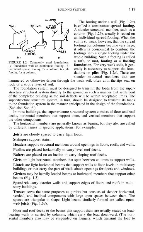
FIGURE 1.2 Commonly used foundations:(a) foundation wall on continuous footing; (b)individual spread footing for a column; (c) pilefooting for a column.
The footing under a wall (Fig. 1.2a)is called a continuous spread footing.A slender structural member, such as acolumn (Fig. 1.2b), usually is seated onan individual spread footing. When thesoil is so weak, however, that the spreadfootings for columns become very large,it often is economical to combine thefootings into a single footing under thewhole building. Such a footing is calleda raft, or mat, footing or a floatingfoundation. For very weak soils, it gen-erally is necessary to support the foun-dations on piles (Fig. 1.2c). These areslender structural members that are
hammered or otherwise driven through the weak soil, often until the tips seat onrock or a strong layer of soil.
The foundation system must be designed to transmit the loads from the super-structure structural system directly to the ground in such a manner that settlementof the completed building as the soil deflects will be within acceptable limits. Thesuperstructure structural system, in turn, should be designed to transmit its loadsto the foundation system in the manner anticipated in the design of the foundations.(See also Sec. 6.)
In most buildings, the superstructure structural system consists of floor and roofdecks, horizontal members that support them, and vertical members that supportthe other components.
The horizontal members are generally known as beams, but they also are calledby different names in specific applications. For example:
Joists are closely spaced to carry light loads.Stringers support stairs.Headers support structural members around openings in floors, roofs, and walls.Purlins are placed horizontally to carry level roof decks.Rafters are placed on an incline to carry sloping roof decks.Girts are light horizontal members that span between columns to support walls.Lintels are light horizontal beams that support walls at floor levels in multistorybuildings or that carry the part of walls above openings for doors and windows.Girders may be heavily loaded beams or horizontal members that support otherbeams (Fig. 1.3).Spandrels carry exterior walls and support edges of floors and roofs in multi-story buildings.Trusses serve the same purposes as girders but consists of slender horizontal,vertical, and inclined components with large open spaces between them. Thespaces are triangular in shape. Light beams similarly formed are called open-web joists (Fig. 1.6d).
Floor and roof decks or the beams that support them are usually seated on load-bearing walls or carried by columns, which carry the load downward. (The hori-zontal members also may be suspended on hangers, which transmit the load to

1.12 SECTION ONE
FIGURE 1.3 Structural-steel skeleton framing for a multistory build-ing. (Courtesy of the American Institute of Steel Construction.)
other horizontal members at a higher level.) The system comprising decks, beams,and bearing walls is known as load-bearing construction (Fig. 1.1). The systemcomposed of decks, beams, and columns is known as skeleton framing (Fig. 1.3).
Both types of systems must be designed to transmit to the foundations vertical(gravity) loads, vertical components of inclined loads, horizontal (lateral) loads, andhorizontal components of inclined loads. Vertical walls and columns have the ap-propriate alignments for carrying vertical loads downward. But acting alone, thesestructural members are inadequate for resisting lateral forces.
One way to provide lateral stability is to incorporate in the system diagonalmembers, called bracing (Fig. 1.3). Bracing, columns, and beams then work to-gether to carry the lateral loads downward. Another way is to rigidly connect beamsto columns to prevent a change in the angle between the beams and columns, thusmaking them work together as a rigid frame to resist lateral movement. Still an-other way is to provide long walls, known as shear walls, in two perpendiculardirections. Lateral forces on the building can be resolved into forces in each ofthese directions. The walls then act like vertical beams cantilevers) in transmittingthe forces to the foundations. (See also Art. 3.2.4.)
Because of the importance of the structural system, the structural membersshould be protected against damage, especially from fire. For fire protection, bracing

BUILDING SYSTEMS 1.13
FIGURE 1.4 Roofs composed of plane surfaces: (a) flat roof; (b) shed roof; (c) pitched roof;(d) hipped roof; (e) gambrel roof; (ƒ) mansard roof; (g) monitored roof; (h) sawtoothroof. (Reprinted with permission from F. S. Merritt and J. Ambrose, ‘‘Building Engineering andSystems Design,’’ 2d ed., Van Nostrand Reinhold, New York.)
may be encased in fire-resistant floors, roofs, or walls. Similarly, columns may beencased in walls, and beams may be encased in floors. Or a fire-resistant material,such as concrete, mineral fiber, or plaster, may be used to box in the structuralmembers (Fig. 1.6c).
See also Secs. 7 to 11.
Systems for Enclosing Buildings. Buildings are enclosed for privacy, to excludewind, rain, and snow from the interior, and to control interior temperature andhumidity. A single-enclosure type of system is one that extends continuously fromthe ground to enclose the floor. Simple examples are cone-like tepees and domeigloos. A multiple-enclosure type of system consists of a horizontal or inclined topcovering, called a roof (Fig. 1.1), and vertical or inclined side enclosures calledwalls.
Roofs may have any of a wide variety of shapes. A specific shape may beselected because of appearance, need for attic space under the roof, requirementsfor height between roof and floor below, desire for minimum enclosed volume,structural economy, or requirements for drainage of rainwater and shedding of snow.While roofs are sometimes given curved surfaces, more often roofs are composedof one or more plane surfaces. Some commonly used types are shown in Fig. 1.4.
The flat roof shown in Fig. 1.4a is nearly horizontal but has a slight pitch fordrainage purposes. A more sloped roof is called a shed roof (Fig. 1.4b). A pitchedroof (Fig. 1.4c) is formed by a combination of two inclined planes. Four inclinedplanes may be combined to form either a hipped roof (Fig. 1.4d) or a gambrel roof(Fig. 1.4e). A mansard roof (Fig. 1.4ƒ) is similar to a hipped roof but, composedof additional planes, encloses a larger volume underneath. Any of the precedingroofs may have glazed openings, called skylights (Fig. 1.4b), for daylighting thebuilding interior. The roofs shown in Fig. 1.4c to ƒ are often used to enclose atticspace. Windows may be set in dormers that project from a sloped roof (Fig. 1.4c).Other alternatives, often used to provide large areas free of walls or columns, in-clude flat-plate and arched or dome roofs.
Monitored roofs are sometimes used for daylighting and ventilating the interior.A monitor is a row of windows installed vertically, or nearly so, above a roof (Fig.

1.14 SECTION ONE
FIGURE 1.5 Types of exterior wall construction: (a) concrete-block wall; (b) wood-framedwall; (c) precast-concrete curtain wall.
1.4g). Figure 1.4h illustrates a variation of a monitored roof that is called a sawtoothroof.
The basic element in a roof is a thin, waterproof covering, called roofing (Sec.12). Because it is thin, it is usually supported on sheathing, a thin layer, or roofdeck, a thick layer, which in turn, is carried on structural members, such as beamsor trusses. The roof or space below should contain thermal insulation (Fig. 1.6cand d).
Exterior walls enclose a building below the roof. The basis element in the wallsis a strong, durable, water-resistant facing. For added strength or lateral stability,this facing may be supplemented on the inner side by a backing or sheathing (Fig.1.5b). For esthetic purposes, an interior facing usually is placed on the inner sideof the backing. A layer of insulation should be incorporated in walls to resistpassage of heat.
Generally, walls may be built of unit masonry, panels, framing, or a combinationof these materials.
Unit masonry consists of small units, such as clay brick, concrete block, glassblock, or clay tile, held together by a cement such as mortar. Figure 1.5a shows awall built of concrete blocks.
Panel walls consist of units much larger than unit masonry. Made of metal,concrete, glass, plastics, or preassembled bricks, a panel may extend from foun-

BUILDING SYSTEMS 1.15
dation to roof in single-story buildings, or from floor to floor or from windowheader in one story to window sill of floor above in multistory buildings. Largepanels may incorporate one or more windows. Figure 1.5c shows a concrete panelwith a window.
Framed walls consist of slender, vertical, closely spaced structural members,tied together with horizontal members at top and bottom, and interior and exteriorfacings. Thermal insulation may be placed between the components. Figure 1.5bshows a wood-framed exterior wall.
Combination walls are constructed of several different materials. Metal, brick,concrete, or clay tile may be used as the exterior facing because of strength, du-rability, and water and fire resistance. These materials, however, are relatively ex-pensive. Consequently, the exterior facing is made thin and backed up with a lessexpensive material. For example, brick may be used as an exterior facing with woodframing or concrete block as the backup.
Exterior walls may be classified as curtain walls or bearing walls. Curtain wallsserve primarily as an enclosure. Supported by the structural system, such wallsneed to be strong enough to carry only their own weight and wind pressure on theexterior face. Bearing walls, in contrast, serve not only as an enclosure but also totransmit to the foundation loads from other building components, such as beams,floors, roofs, and other walls (Fig. 1.5a and b). (See also Sec. 11.)
Openings are provided in exterior walls for a variety of purposes, but mainlyfor windows and doors. Where openings occur, structural support must be providedover them to carry the weight of the wall above and any other loads on that portionof the wall. Usually, a beam called a lintel is placed over openings in masonrywalls (Fig. 1.5a) and a beam called a top header is set over openings in wood-framed walls.
A window usually consists of transparent glass or plastics (glazing) held in placeby light framing, called sash. The window is fitted into a frame secured to thewalls (Fig. 1.5a). For sliding windows, the frame carries guides in which the sashslides. For swinging windows, stops against which the window closes are built intothe frame.
Hardware is provided to enable the window to function as required. For mov-able windows, the hardware includes grips for moving them, locks, hinges forswinging windows, and sash balances and pulleys for vertically sliding windows.
The main purposes of windows are to illuminate the building interior with day-light, to ventilate the interior, and to give occupants a view of the outside. For retailstores, windows may have the major purpose of giving passersby a view of itemsdisplayed inside. (See also Sec. 11.)
Doors are installed in exterior walls to give access to or from the interior or toprevent such access. For similar reasons, doors are also provided in interior wallsand partitions. Thus, a door may be part of a system for enclosing a building or acomponent of a system for enclosing interior spaces.
Systems for Enclosing Interior Spaces. The interior of a building usually is com-partmented into spaces or rooms by horizontal dividers (floor-ceiling or roof-ceilingsystems) and vertical dividers (interior walls and partitions). (The term partitions isgenerally applied to non-load-bearing walls.)
Floor-Ceiling Systems. The basic element of a floor is a load-carrying deck.For protection against wear, esthetic reasons, foot comfort, or noise control, a floorcovering often is placed over the deck, which then may be referred to as a subfloor.Figure 1.6a shows a concrete subfloor with a flexible-tile floor covering. A hollow-cold-formed steel deck is incorporated in the subfloor to house electric wiring.

1.16 SECTION ONE
(a)
FIGURE 1.6 Examples of floor-ceiling and roof-ceiling systems. (a) Concrete structural slabcarries hollow-steel deck, concrete fill, and flexible tile flooring. (b) Acoustical-tile ceilingincorporating a lighting fixture with provisions for air distribution is suspended below a floor.(c) Insulated roof and steel beams are sprayed with mineral fiber for fire protection. (d) In-sulated roof and open-web joists are protected by a fire-rated suspended ceiling.
In some cases, a subfloor may be strong and stiff enough to span, unaided, longdistances between supports provided for it. In other cases, the subfloor is closelysupported on beams. The subfloor in Fig. 1.6a, for example, is shown constructedintegrally with concrete beams, which carry the loads from the subfloor to bearingwalls or columns.
The underside of a floor or roof and of beams supporting it, including decorativetreatment when applied to that side, is called a ceiling. Often, however, a separate

BUILDING SYSTEMS 1.17
FIGURE 1.6 (Continued)
ceiling is suspended below a floor or roof for esthetic or other reasons. Figure 1.6bshows such a ceiling. It is formed with acoustical panels and incorporates a lightingfixture and air-conditioning inlets and outlets.
Metal and wood subfloors and beams require fire protection. Figure 1.6c showsa roof and its steel beams protected on the underside by a sprayed-on mineral fiber.Figure 1.6d shows a roof and open-web steel joists protected on the underside bya continuous, suspended, fire-resistant ceiling. As an alternative to encasement inor shielding by a fire-resistant material, wood may be made fire-resistant by treat-ment with a fire-retardant chemical.
Fire Ratings. Tests have been made, usually in conformance with E119, ‘‘Stan-dard Methods of Tests of Building Construction and Materials,’’ developed byASTM, to determine the length of time specific assemblies of materials can with-stand a standard fire, specified in E119. On the basis of test results, each construc-tion is assigned a fire rating, which gives the time in hours that the assembly canwithstand the fire. Fire ratings for various types of construction may be obtainedfrom local, state, or model building codes or the ‘‘Fire Resistance Design Manual,’’published by the Gypsum Association.
Interior Walls and Partitions. Interior space dividers do not have to withstandsuch severe conditions as do exterior walls. For instance, they are not exposed torain, snow, and solar radiation. Bearing walls, however, must be strong enough to

1.18 SECTION ONE
FIGURE 1.7 Types of partitions: (a) non-load-bearing; (b) gypsumboard on metal studs; (c)gypsumboard face panels laminated to a gypsum core panel; (d) concrete bearing wall, floors,and beams. (Reprinted with permission from F. S. Merritt and J. Ambrose, ‘‘Building Engi-neering and Systems Design,’’ 2d ed., Van Nostrand Reinhold, New York.)
transmit to supports below them the loads to which they are subjected. Usually,such interior walls extend vertically from the roof to the foundations of a buildingand carry floors and roof. The basic element of a bearing wall may be a solid core,as shown in Fig. 1.7d, or closely spaced vertical framing (studs), as shown in Fig.1.7b.
Non-load-bearing partitions do not support floors or roof. Hence, partitions maybe made of such thin materials as sheet metal (Fig. 1.7a), brittle materials as glass(Fig. 1.7a), or weak materials as gypsum (Fig. 1.7c). Light framing may be usedto hold these materials in place. Because they are non-load-bearing, partitions maybe built and installed to be easily shifted or to be foldable, like a horizontally slidingdoor. (see also Sec. 11.)
Wall Finishes. Walls are usually given a facing that meets specific architecturalrequirements for the spaces enclosed. Such requirements include durability underindoor conditions, ease of maintenance, attractive appearance, fire resistance, waterresistance, and acoustic properties appropriate to the occupancy of the space en-closed. The finish may be the treated surface of the exposed wall material, such asthe smooth, painted face of a sheet-metal panel, or a separate material, such asplaster, gypsumboard, plywood, or wallpaper. (See also Sec. 11.)
Doors. Openings are provided in interior walls and partitions to permit passageof people and equipment from one space to another. Doors are installed in theopenings to provide privacy, temperature, odor and sound control, and control pas-sage.
Usually, a door frame is set around the perimeter of the opening to hold thedoor in place (Fig. 1.8). Depending on the purpose of the door, size, and otherfactors, the door may be hinged to the frame at top, bottom, or either side. Or thedoor may be constructed to slide vertically or horizontally or to rotate about avertical axis in the center of the opening (revolving door). (See also Sec. 11.)
Hardware is provided to enable the door to function as required. For example,hinges are provided for swinging doors, and guides are installed for sliding doors.Locks or latches are placed in or on doors to prevent them from being opened.Knobs or pulls are attached to doors for hand control.

BUILDING SYSTEMS 1.19
FIGURE 1.8 Example of door and frame.
Builder’s Hardware. This is a generalterm applied to fastenings and devices,such as nails, screws, locks, hinges, andpulleys. These items generally are clas-sified as either finishing hardware orrough hardware (Sec. 11).
Plumbing. The major systems for con-veyance of liquids and gases in pipeswithin a building are classified asplumbing. Plumbing pipes usually areconnected to others that extend outsidethe building to a supply source, such asa public water main or utility gas main,or to a disposal means, such as a sewer.
For health, safety, and other reasons, pipes of different types of plumbing systemsmust not be interconnected, and care must be taken to prevent flow from one systemto another.
The major purposes of plumbing are: (1) to convey water and heating gas, ifdesired, from sources outside a building to points inside where the fluid or gas isneeded, and (2) to collect wastewater and storm water in the building, on the roof,or elsewhere on the site and convey the liquid to sewers outside the building.
For these purposes, plumbing requires fixtures for collecting discharged waterand wastes; pipes for supply and disposal; valves for controlling flow; drains, andother accessories. For more details, see Sec. 14.
Heating, Ventilation, and Air-Conditioning (HVAC). Part of the environmentalcontrol systems within buildings, along with lighting and sound control, HVAC isoften necessary for the health and comfort of building occupants. Sometimes, how-ever, HVAC may be needed for manufacturing processes, product storage, or op-eration of equipment, such as computers. HVAC usually is used to control temper-ature, humidity, air movement, and air quality in the interior of buildings.
Ventilation is required to supply clean air for breathing, to furnish air for op-eration of combustion equipment, and to remove contaminated air. Ventilation, how-ever, also can be used for temperature control by bringing outside air into a buildingwhen there is a desirable temperature difference between that air and the interiorair.
The simplest way to ventilate is to open windows. When this is not practicable,mechanical ventilation is necessary. This method employs fans to draw outside airinto the building and distribute the air, often through ducts, to interior spaces. Themethod, however, can usually be used only in mild weather. To maintain comfortconditions in the interior, the fresh air may have to be heated in cold weather andcooled in hot weather.
Heating and cooling of a building interior may be accomplished in any of amultitude of ways. Various methods are described in Sec. 13.
Lighting. For health, safety, and comfort of occupants, a building interior shouldbe provided with an adequate quantity of light, good quality of illumination, andproper color of light. The required illumination may be supplied by natural orartificial means.

1.20 SECTION ONE
Daylight is the source of natural illumination. It enters a building through afenestration, such as windows in the exterior walls or monitors or skylights on theroof.
Artificial illumination can be obtained through consumption of electrical energyin incandescent, fluorescent, electroluminescent, or other electric lamps. The lightsource is housed in a luminaire, or lighting fixture. More details are given in Sec.15.
Acoustics. The science of sound, its production, transmission, and effects are ap-plied in the building design for sound and vibration control.
A major objective of acoustics is provision of an environment that enhancescommunication in the building interior, whether the sound is created by speech ormusic. This is accomplished by installation of enclosures with appropriate acousticproperties around sound sources and receivers. Another important objective is re-duction or elimination of noise—unwanted sound—from building interiors. Thismay be accomplished by elimination of the noise at the source, by installation ofsound barriers, or by placing sound-absorbing materials on the surfaces of enclo-sures.
Still another objective is reduction or elimination of vibrations that can annoyoccupants, produce noise by rattling loose objects, or crack or break parts or con-tents of a building. The most effective means of preventing undesirable vibrationsis correction of the source. Otherwise, the source should be isolated from the build-ing structure and potential transmission paths should be interrupted with carefullydesigned discontinuities.
Electric Power and Communication Systems. Electric power is generally boughtfrom nearby utility and often supplemented for emergency purposes by power frombatteries or a generating plant on the site. Purchased power is brought from thepower lines connected to the generating source to an entrance control point and ameter in the building. From there, conductors distribute the electricity throughoutthe building to outlets where the power can be tapped for lighting, heating, andoperating electric devices.
Two interrelated types of electrical systems are usually provided within a build-ing. One type is used for communications, including data, telephone, television,background music, paging, signal and alarm systems. The second type serves theother electrical needs of the building and its occupants. For more details, see Sec.15 and 18.
In addition to conductors and outlets, an electrical system also incorporates de-vices and apparatus for controlling electric voltage and current. Because electricitycan be hazardous, the system must be designed and installed to prevent injury tooccupants and damage to building components.
For more details, see Sec. 15.
Vertical-Circulation Elements. In multistory buildings, provision must be madefor movement of people, supplies, and equipment between the various levels. Thismay be accomplished with ramps, stairs, escalators, elevators, dumbwaiters, verticalconveyors, pneumatic tubes, mail chutes, or belt conveyors. Some of the mechanicalequipment, however, may not be used for conveyance of people.
A ramp, or sloping floor, is often used for movement of people and vehicles insuch buildings as stadiums and garages. In most buildings, however, stairs are in-stalled because they can be placed on a steeper slope and therefore occupy lessspace than ramps. Nevertheless, federal rules require at least one handicap acces-sible entrance for all new buildings.
BUILDING SYSTEMS 1.21
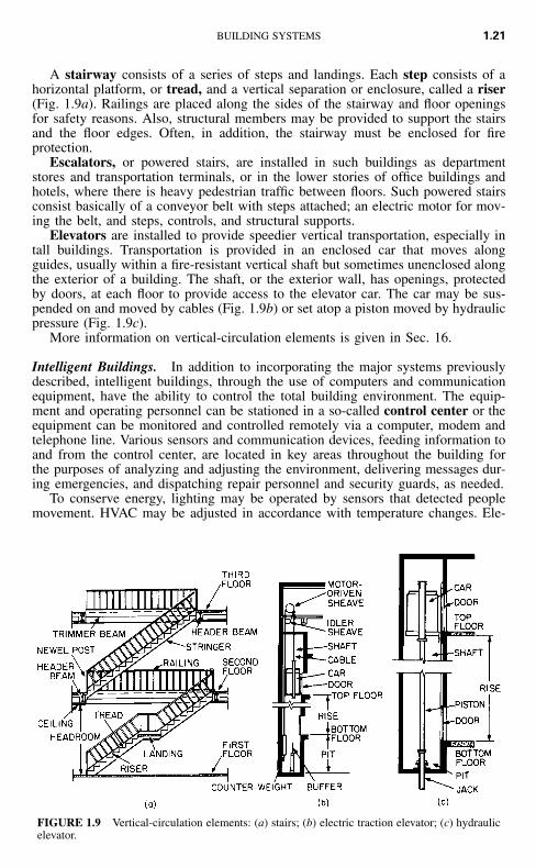
FIGURE 1.9 Vertical-circulation elements: (a) stairs; (b) electric traction elevator; (c) hydraulicelevator.
A stairway consists of a series of steps and landings. Each step consists of ahorizontal platform, or tread, and a vertical separation or enclosure, called a riser(Fig. 1.9a). Railings are placed along the sides of the stairway and floor openingsfor safety reasons. Also, structural members may be provided to support the stairsand the floor edges. Often, in addition, the stairway must be enclosed for fireprotection.
Escalators, or powered stairs, are installed in such buildings as departmentstores and transportation terminals, or in the lower stories of office buildings andhotels, where there is heavy pedestrian traffic between floors. Such powered stairsconsist basically of a conveyor belt with steps attached; an electric motor for mov-ing the belt, and steps, controls, and structural supports.
Elevators are installed to provide speedier vertical transportation, especially intall buildings. Transportation is provided in an enclosed car that moves alongguides, usually within a fire-resistant vertical shaft but sometimes unenclosed alongthe exterior of a building. The shaft, or the exterior wall, has openings, protectedby doors, at each floor to provide access to the elevator car. The car may be sus-pended on and moved by cables (Fig. 1.9b) or set atop a piston moved by hydraulicpressure (Fig. 1.9c).
More information on vertical-circulation elements is given in Sec. 16.
Intelligent Buildings. In addition to incorporating the major systems previouslydescribed, intelligent buildings, through the use of computers and communicationequipment, have the ability to control the total building environment. The equip-ment and operating personnel can be stationed in a so-called control center or theequipment can be monitored and controlled remotely via a computer, modem andtelephone line. Various sensors and communication devices, feeding information toand from the control center, are located in key areas throughout the building forthe purposes of analyzing and adjusting the environment, delivering messages dur-ing emergencies, and dispatching repair personnel and security guards, as needed.
To conserve energy, lighting may be operated by sensors that detected peoplemovement. HVAC may be adjusted in accordance with temperature changes. Ele-

1.22 SECTION ONE
vators may be programmed for efficient handling of variations in traffic patternsand may be equipped with voice synthesizers to announce floor stops and giveadvice in emergencies. In addition, intelligent buildings are designed for ease andflexibility in providing for changes in space use, piping, electrical conductors, andinstalled equipment. See also Arts. 3.5.12 and 3.7.2.
(F. S. Merritt and J. Ambrose, ‘‘Building Engineering and Systems Design,’’ 2ndEd., Van Nostrand Reinhold, New York.)
1.8 VALUE ENGINEERING
As indicated in Art. 1.3, the client in the initial design phase develops a program,or list of requirements. The goal of the designers is to select a system that meetsthese requirements. Before the designers do this, however, it is advisable for themto question whether the requirements represent the client’s actual needs. Can thecriteria and standards affecting the design be made less stringent? After the programhas been revised to answer these questions, the designers select a system. Next, itis advisable for the designers to question whether the system provides the bestvalue at the lowest cost. Value engineering is a useful procedure for answering thisquestion and selecting a better alternative if the answer indicates this is desirable.
Value engineering is the application of the scientific method to the study ofvalues of systems. The major objective of value engineering in building design andconstruction is reduction of initial and life-cycle costs (Art. 1.6). Thus, value en-gineering has one of the objectives of systems design, in which the overall goal isproduction of an optimum building, and should be incorporated in the systems-design procedure.
The scientific method, which is incorporated in the definitions of value engi-neering and systems design, consists of the following steps:
1. Collection of data and observations of natural phenomena2. Formulation of a hypothesis capable of predicting future observations3. Testing of the hypothesis to verify the accuracy of its predictions and abandon-
ment or improvement of the hypothesis if it is inaccurate
Those who conduct or administer value studies are often called value engineers,or value analysts. They generally are organized into an interdisciplinary team forvalue studies for a specific project. Sometimes, however, an individual, such as anexperienced contractor, performs value engineering services for the client for a feeor a percentage of savings achieved by the services.
Value Analysis. Value is a measure of benefits anticipated from a system or fromthe contribution of a component to system performance. This measure must becapable of serving as a guide in a choice between alternatives in evaluations ofsystem performance. Because generally in comparisons of systems only relativevalues need be considered, value takes into account both advantages and disadvan-tages, the former being considered positive and the latter negative. It is thereforepossible in comparisons of systems that the value of a component of a system maybe negative and subtracts of systems from the overall performance of the system.
System evaluations would be relatively easy if a monetary value could alwaysbe placed on performance. Then, benefits and costs could be compared directly.

BUILDING SYSTEMS 1.23
Value, however, often must be based on a subjective decision of the client. Forexample, how much extra is an owner willing to pay for beauty, prestige, or bettercommunity relations? Will the owner accept gloom, glare, draftiness, or noise fora savings in cost? Consequently, other values than monetary must be considered invalue analysis. Such considerations require determination of the relative importanceof the client’s requirements and weighting of values accordingly.
Value analysis is the part of the value-engineering procedure devoted to inves-tigation of the relation between costs and values of components and systems andalternatives to these. The objective is to provide a rational guide for selection ofthe lowest-cost system that meets the client’s actual needs.
Measurement Scales. For the purposes of value analysis, it is essential that char-acteristics of a component or system on which a value is to be placed be distin-guishable. An analyst should be able to assign different numbers, not necessarilymonetary, to values that are different. These numbers may be ordinates of any oneof the following four measurement scales: ratio, interval, ordinal, nominal.
Ratio Scale. This scale has the property that, if any characteristic of a systemis assigned a value number k, any characteristic that is n times as large must beassigned a value number nk. Absence of the characteristic is assigned the valuezero. This type of scale is commonly used in engineering, especially in cost com-parisons. For example, if a value of $10,000 is assigned to system A and of $5000to system B, then A is said to cost twice as much as B.
Interval Scale. This scale has the property that equal intervals between assignedvalues represent equal differences in the characteristic being measured. The scalezero is assigned arbitrarily. The Celsius scale of temperature measurements is agood example of an interval scale. Zero is arbitrarily established as the temperatureat which water freezes; the zero value does not indicate absence of heat. The boilingpoint of water is arbitrarily assigned the value of 100. The scale between 0 and100 is then divided into 100 equal intervals called degrees (�C). Despite the arbi-trariness of the selection of the zero point, the scale is useful in heat measurement.For example, changing the temperature of an objective from 40�C to 60�C, anincrease of 20�C, requires twice as much heat as changing the temperature from45�C to 55�C, an increase of 10�C.
Ordinal Scale. This scale has the property that the magnitude of a value numberassigned to a characteristic indicates whether a system has more, or less, of thecharacteristic than another system has or is the same with respect to that charac-teristic. For example, in a comparison of the privacy afforded by different types ofpartitions, each may be assigned a number that ranks it in accordance with thedegree of privacy that it provides. Partitions with better privacy are given largernumbers. Ordinal scales are commonly used when values must be based on sub-jective judgments of nonquantifiable differences between systems.
Nominal Scale. This scale has the property that the value numbers assigned toa characteristic of systems being compared merely indicate whether the systemsdiffer in this characteristic. But no value can be assigned to the difference. Thistype of scale is often used to indicate the presence or absence of a characteristicor component. For example, the absence of a means of access to equipment formaintenance may be represented by zero or a blank space, whereas the presenceof such access may be denoted by 1 or X.
Weighting. In practice, construction cost usually is only one factor, perhaps theonly one with a monetary value, of several factors that must be evaluated in acomparison of systems. In some cases, some of the other characteristics of the

1.24 SECTION ONE
TABLE 1.1 Comparison of Alternative Partitions*
CharacteristicsRelative
importance
Alternatives
1All metal
Relativevalue
Weightedvalue
2Glass and metal
Relativevalue
Weightedvalue
Construction cost 8 10 80 8 64Appearance 9 7 63 9 81Sound transmission 5 5 25 4 20Privacy 3 10 30 2 6Visibility 10 0 0 8 80Movability 2 8 16 8 16Power outlets 4 0 0 0 0Durability 10 9 90 9 90Low maintenance 8 7 56 5 40
Total weighted values 360 397Cost $12,000 $15,000Ratio of values to cost 0.0300 0.0265
* Reprinted with permission from F. S. Merritt, ‘‘Building Engineering and Systems Design,’’ Van Nos-trand Reinhold Company, New York.
system may be more important to the owner than cost. Under such circumstances,the comparison may be made by use of an ordinal scale for ranking each charac-teristic and then weighting the rankings in accordance with the importance of thecharacteristic to the owner.
As an example of the use of this procedure, calculations for comparison of twopartitions are shown in Table 1.1. Alternative 1 is an all-metal partition and alter-native 2 is made of glass and metal.
In Table 1.1, characteristics of concern in the comparison are listed in the firstcolumn. The numbers in the second column indicate the relative importance of eachcharacteristic to the owner: 1 denotes lowest priority and 10 highest priority. Theseare the weights. In addition, each of the partitions is ranked on an ordinal scale,with 10 as the highest value, in accordance with the degree to which it possesseseach characteristic. These rankings are listed as relative values in Table 1.1. Forconstruction cost, for instance, the metal partition is assigned a relative value of 10and the glass-metal partition a value of 8, because the metal partition costs a littleless than the other one. In contrast, the glass-metal partition is given a relative valueof 8 for visibility, because the upper portion is transparent, whereas the metalpartition has a value of zero, because it is opaque.
To complete the comparison, the weight of each characteristic is multiplied bythe relative value of the characteristic for each partition and entered in Table 1.1as a weighted value. For construction cost, for example, the weighted values are8 � 10 � 80 for the metal partition and 8 � 8 � 64 for the glass-metal partition.The weighted values for each partition are then added, yielding 360 for alternative1 and 397 for alternative 2. While this indicates that the glass-metal partition isbetter, it may not be the best for the money. To determine whether it is, the weightedvalue for each partition is divided by its cost, yielding 0.0300 for the metal partition

BUILDING SYSTEMS 1.25
and 0.0265 for the other. Thus, the metal partition appears to offer more value forthe money and would be recommended.
Economic Comparisons. In a choice between alternative systems, only the dif-ferences between system values are significant and need to be compared.
Suppose, for example, the economic effect of adding 1 in of thermal insulationto a building is to be investigated. In a comparison, it is not necessary to computethe total cost of the building with and without the insulation. Generally, the valueanalyst need only subtract the added cost of 1 in of insulation from the decreasein HVAC cost to obtain the net saving or cost increase resulting from addition ofinsulation. A net saving would encourage addition of insulation. Thus, a decisioncan be reached without the complex computation of total building cost.
In evaluating systems, value engineers must take into account not only initialand life-cycle costs but also the return the client wishes to make on the investmentin the building. Generally, a client would like not only to maximize profit, thedifference between revenue from use of the building and total costs, but also toensure that the rate of return, the ratio of profit to investment, is larger than all ofthe following:
Rate of return expected from the type of businessInterest rate for borrowed moneyRate for government bonds or notesRate for highly rated corporate bonds
The client is concerned with interest rates because all costs represent money thatmust be borrowed or that could otherwise be invested at a current interest rate. Theclient also has to be concerned with time, measured from the date at which aninvestment is made, because interest cost increases with time. Therefore, in eco-nomic comparisons of systems, interest rates and time must be taken into account.(Effects of monetary inflation can be taken into account in much the same way asinterest.)
An economic comparison usually requires evaluation of initial capital invest-ments, salvage values after several years, annual disbursements and annual reve-nues. Because each element in such a comparison may have associated with it anexpected useful life different from that of the other elements, the different types ofcosts and revenues must be made commensurable by reduction to a common basis.This is commonly done by either:
1. Converting all costs and revenues to equivalent uniform annual costs and income2. Converting all costs and revenues to present worth of all costs and revenues at
time zero.
Present worth is the money that, invested at time zero, would yield at latertimes required costs and revenues at a specified interest rate. In economic compar-isons, the conversions should be based on a rate of return on investment that isattractive to the client. It should not be less than the interest rate the client wouldhave to pay if the amount of the investment had to be borrowed. For this reason,the desired rate of return is called interest rate in conversions. Calculations alsoshould be based on actual or reasonable estimates of time periods. Salvage values,for instance, should be taken as the expected return on sale or trade-in of an item

1.26 SECTION ONE
after a specific number of years that it has been in service. Interest may be consid-ered compounded annually.
Future Value. Based on the preceding assumptions, a sum invested at time zeroincreases in time to
nS � P(1 � i) (1.1)
where S � future amount of money, equivalent to P, at the end of n periods oftime with interest i
i � interest raten � number of interest periods, yearsP � sum of money invested at time zero � present worth of S
Present Worth. Solution of Eq. (1.1) for P yields the present worth of a sumof money S at a future date:
nP � S(1 � i) (1.2)
The present worth of payments R made annually for n years is
�n1 � (1 � i)P � R (1.3)
i
The present worth of the payments R continued indefinitely can be obtained fromEq. (1.3) by making n infinitely large:
RP � (1.4)
i
Capital Recovery. A capital investment P at time zero can be recovered in nyears by making annual payments of
i iR � P � P � i (1.5)� ��n n1 � (1 � i) (1 � i) � 1
When an item has salvage value V after n years, capital recovery R can be computedfrom Eq. (1.5) by subtraction of the present worth of the salvage value from thecapital investment P.
i�nR � [P � V(1 � i) ] � i (1.6)� �n(1 � i) � 1
Example. To illustrate the use of these formulas, an economic comparison is madein the following for two air-conditioning units being considered for an office build-ing. Costs are estimated as follows:
Unit 1 Unit 2
Initial cost $300,000 $500,000Life, years 10 20Salvage value $50,000 $100,000Annual costs $30,000 $20,000

BUILDING SYSTEMS 1.27
TABLE 1.2 Example Comparison of Two Air-Conditioning Units
Unit 1 Unit 2
Initial investment $300,000 $500,000Present worth of replacement cost in 10
years P � V at 8% interest [Eq.(1.2)]
115,800
Present worth of annual cost for 20years at 8% interest [Eq. (1.3)]
294,540 196,360
Present worth of all costs 710,340 696,360
Revenue:Present value of salvage value after 20
years at 8% interest [Eq. (1.2)]10,730 21,450
Net cost:Present worth of net cost in 20 years at
8% interest$699,610 $674,910
Cost of operation, maintenance, repairs, property taxes, and insurance are includedin the annual costs. The present-worth method is used for the comparison, withinterest rate i � 8%.
Conversion of all costs and revenues to present worth must be based on a com-mon service life, although the two units have different service lives, 10 and 20years, respectively. For the purpose of the conversion, it may be assumed thatreplacement assets will repeat the investment and annual costs predicted for theinitial asset. (Future values, however, should be corrected for monetary inflation.)In some cases, it is convenient to select for the common service life the leastcommon multiple of the lives of the units being compared. In other cases, it maybe more convenient to assume that the investment and annual costs continue in-definitely. The present worth of such annual costs is called capitalized cost.
For this example, a common service life of 20 years, the least common multipleof 10 and 20, is selected. Hence, it is assumed that unit 1 will be replaced at theend of the tenth period at a cost of $300,000 less the salvage value. Similarly, thereplacement unit will be assumed to have the same salvage value after 20 years.
The calculations in Table 1.2 indicate that the present worth of the net cost ofunit 2 is less than that for unit 1. If total cost during the twenty year period werethe sole consideration, purchase of unit 2 would be recommended.
ASTM has developed several standard procedures for making economic studiesof buildings and building systems, in addition to ASTM E917 for measuring life-cycle costs, mentioned previously. For example, ASTM E964 is titled Practice forMeasuring Benefit-to-Cost and Savings-to-Investment Ratios for Buildings andBuilding Systems. Other standards available present methods for measuring internalrate of return, net benefits, and payback. ASTM also has developed computer pro-grams for these calculations.
Value Analysis Procedure. In building design, value analysis generally starts witha building system or subsystem proposed by the architect and consultants. The clientor the client’s representative appoints an interdisciplinary team to study the systemor subsystem and either recommend its use or propose a more economical alter-native. The team coordinator sets goals and priorities for the study and may appointtask groups to study parts of the building in accordance with the priorities. Thevalue analysts should follow a systematic, scientific procedure for accomplishing

1.28 SECTION ONE
all the necessary tasks that comprise a value analysis. The procedure should providean expedient format for recording the study as it progresses, assure that consider-ation has been given to all information, some of which may have been overlookedin development of the proposed system, and logically resolve the analysis intocomponents that can be planned, scheduled, budgeted, and appraised.
The greatest cost reduction can be achieved by analysis of every component ofa building. This, however, is not practical, because of the short time usually avail-able for the study and because the cost of the study increases with time. Hence, itis advisable that the study concentrate on those building systems (or subsystems)whose cost is a relatively large percentage of the total building (or system) cost,because those components have possibilities for substantial cost reduction.
During the initial phase of value analysis, the analysts should obtain a completeunderstanding of the building and its major systems by rigorously reviewing theprogram, proposed design and all other pertinent information. They should alsodefine the functions, or purposes, of each building component to be studied andestimate the cost of accomplishing the functions. Thus, the analysts should performa systems analysis, as indicated in Art. 1.2, answer the questions listed in Art 1.2for the items to be studied, and estimate the initial and life-cycle costs of the items.
In the second phase of value analysis, the analysts should question the cost-effectiveness of each component to be studied. Also, by use of imagination andcreative techniques, they should generate several alternative means for accomplish-ing the required functions of the component. Then, in addition to answers to thequestions in Art. 1.2, the analysts should obtain answers to the following questions:
Do the original design and each alternative meet performance requirements?What does each cost installed and over the life cycle?Will it be available when needed? Will skilled labor be available?Can any components be eliminated?What other components will be affected by adoption of an alternative? Whatwill the resulting changes in the other components cost? Will there be a netsaving in cost?
In investigating the possibility of elimination of a component, the analysts alsoshould see if any part of it can be eliminated, if two parts or more can be combinedinto one, and if the number of different sizes and types of an element can bereduced. If costs might be increased by use of a nonstandard or unavailable item,the analysts should consider substitution of a more appropriate alternative. In ad-dition, consideration should be given to simplification of construction or installationof components and to ease of maintenance and repair.
In the following phase of value analysis, the analysts should critically evaluatethe original design and alternatives. The ultimate goal should be recommendationof the original design and alternative, whichever offers the greatest value and cost-savings potential. The analysts also should submit estimated costs for the originaldesign and the alternative.
In the final phase, the analysts should prepare and submit to the client or theclient’s representative who appointed them a written report on the study and re-sulting recommendations. Also, they should submit a workbook containing detailedbackup information.
Value engineering should start during the conceptual phase of design. Then, ithas the greatest impact on cost control and no cost is involved in making designchanges. During later design phases, design changes involve some cost, especially

BUILDING SYSTEMS 1.29
when substitution of major subsystems is involved, but the cost is nowhere near asgreat as when changes are made during construction. Such changes should beavoided if possible. Value engineering, however, should be applied to the projectspecifications and construction contract. Correction of unnecessary and overcon-servative specifications and contract provisions offers considerable potential for costreduction.
(E. D. Heller, ‘‘Value Management: Value Engineering and Cost Reduction,’’Addison-Wesley, Reading, Mass.; L. D. Miles, ‘‘Techniques of Value Analysis andEngineering,’’ McGraw-Hill Publishing Co., New York; A Mudge, ‘‘Value Engi-neering,’’ McGraw-Hill Publishing Company, New York; M. C. Macedo, P. V. Dob-row, and J. J. O’Rourke, ‘‘Value Management for Construction,’’ John Wiley &Sons, Inc., New York.)
1.9 EXECUTION OF SYSTEMS DESIGN
The basic traditional design procedure (Art. 1.3), which has been widely used formany years, and commonly used variations of it have resulted in many excellentbuildings. It needs improvement, however, because clients cannot be certain thatits use gives the best value for the money or that the required performance couldnot have been attained at lower cost. The uncertainty arises because historically:
1. Actual construction costs often exceed low bids or negotiated prices, because ofdesign changes during construction; unanticipated delays during construction,which increase costs; and unforeseen conditions, such as unexpectedly poor sub-surface conditions that make excavation and foundation construction more ex-pensive.
2. Construction, operation, or maintenance costs are higher than estimated, becauseof design mistakes or omissions.
3. Separation of design and construction into different specialties leads to under-estimated or overestimated construction costs and antagonistic relations betweendesigners and builders.
4. Construction costs are kept within the client’s budget at the expense of laterhigher operating, maintenance, and repair costs.
5. Coordination of the output of architects and consultants is not sufficiently closefor production of an optimum building for the client’s actual needs.
One objective of systems design is to correct these defects. This can be donewhile retaining the desirable features of traditional procedures, such as developmentof building design in stages, with progressively more accurate cost estimates andfrequent client review. Systems design therefore should at least do the following:
1. Question the cost effectiveness of proposed building components and stimulategeneration of lower-cost alternatives that achieve the required performance. Thiscan be done by incorporating value engineering in systems design.
2. More closely coordinate the work of various design specialists and engage build-ing construction and operation experts to assist in design.
3. Take into account both initial and life-cycle costs.

1.30 SECTION ONE
4. Employ techniques that will reduce the number of design mistakes and omissionsthat are not discovered until after construction starts.
Systems Design Procedure. Article 1.2 defines systems and explains that systemsdesign comprises a rational, orderly series of steps that leads to the best decisionfor a given set of conditions. Article 1.2 also lists the basic components of theprocedure as analysis, synthesis, appraisal, and feedback. Following is a more for-mal definition:
Systems design is the application of the scientific method to selection and as-sembly of components or subsystems to form the optimum system to attain specifiedgoals and objectives while subject to given constraints and restrictions.
The scientific method is defined in Art. 1.8. Goals, objectives, and constraintsare discussed later.
Systems design of buildings, in addition to correcting defects in traditional de-sign, must provide answers to the following questions:
1. What does the client actually want the building to accomplish (goals, objectives,and associated criteria)?
2. What conditions exist, or will exist after construction, that are beyond the de-signers’ control?
3. What requirements for the building or conditions affecting system performancedoes design control (constraints and associated standards)?
4. What performance requirements and time and cost criteria can the client anddesigners use to appraise system performance?
Collection of information necessary for design of the building starts at the in-ception of design and may continue through the contract documents phase. Datacollection is an essential part of systems design but because it is continuousthroughout design it is not listed as one of the basic steps.
For illustrative purposes, the systems design procedure is shown resolved intonine basic steps in Fig. 1.10. Because value analysis is applied in step 5, steps 4through 8 covering synthesis, analysis, and appraisal may be repeated several times.Each iteration should bring the design closer to the optimum.
In preparation for step 1, the designers should secure a building program andinformation on existing conditions that will affect building design. In step 1, thedesigners use the available information to define goals to be met by the system.
Goals. These state what the building is to accomplish, how it will affect theenvironment and other systems, and how other systems and the environment willaffect the building. Goals should be generalized but brief statements, encompassingall the design objectives. They should be sufficiently specific, however, to guidegeneration of initial and alternative designs and control selection of the best alter-native.
A simple example of a goal is: Design a branch post-office building with 100employees to be constructed on a site owned by the client. The building shouldharmonize with neighboring structures. Design must be completed within 90 daysand construction within 1 year. Construction cost is not to exceed $500,000.
When systems design is applied to a subsystem, goals serve the same purposeas for a system. They indicate the required function of the subsystem and how itaffects and is affected by other systems.
Objectives. With the goals known, the designers can advance to step 2 anddefine the system objectives. These are similar to goals but supply in detail therequirements that the system must satisfy to attain the goals.

BUILDING SYSTEMS 1.31
FIGURE 1.10 Basic steps in systems design in addition to collection of necessary information.

1.32 SECTION ONE
In listing objectives, the designers may start with broad generalizations that theylater develop at more detailed levels to guide design of the system. Some objectives,such as minimization of initial costs, life-cycle costs and construction time, shouldbe listed. Other objectives that apply to the design of almost every building, suchas the health, safety, and welfare objectives of the building, zoning, and Occupa-tional Safety and Health Administration regulations, are too numerous to list andmay be adopted by reference. Objectives should be sufficiently specific to guidethe planning of building interior spaces and selection of specific characteristics forthe building and its components: appearance, strength, durability, stiffness, opera-tional efficiency, maintenance, and fire resistance. Also, objectives should specifythe degree of control needed for operation of systems provided to meet the otherobjectives.
At least one criterion must be associated with each objective. The criterion is arange of values within which the performance of the system must lie for the ob-jective to be met. The criterion should be capable of serving as a guide in evalu-ations of alternative systems. For example, for fire resistance of a wall, the criterionmight be 2-hr fire rating.
In addition to establishing criteria, the designers should weight the objectives inaccordance with the relative importance of the objectives to the client (Art. 1.8).These weights should also serve as guides in comparisons of alternatives.
System Constraints. In step 2 of systems design, the designers should alsodefine constraints on the system. Constraints are restrictions on the values of designvariables that represent properties of the system and are controllable by the de-signers. Designers are seldom completely free to choose any values desired forcontrollable variables because of various restrictions, which may be legal ones suchas building or zoning code requirements, or may be economic, physical, chemical,temporal, psychological, sociological, or esthetic requirements. Such restrictionsmay fix the values of the controllable variables or establish a range in which theymust lie.
At least one standard must be associated with each constraint. A standard is avalue or range of values governing a property of the system. The standard speci-fying a fixed value may be a minimum or maximum value.
For example, a designer may be seeking to determine the thickness of a load-bearing brick wall. The local building code may state that such a wall may not beless than 8 in thick. This requirement is a minimum standard. The designer maythen select a wall thickness of 8 in or more. The requirements of other systems,however, may indicate that the wall thickness may not exceed 16 in. This is amaximum standard. Furthermore, bricks may be available only in nominal widthsof 4 in. Hence, the constraints limit the values of the controllable variable, in thiscase wall thickness, to 8, 12, or 16 in.
Synthesis. In step 3, the designers must conceive at least one system that sat-isfies the objectives and constraints. For this, they rely on their past experience,knowledge, imagination, and creative skills and on advice from consultants, in-cluding value engineers, construction experts, and experienced operators of the typeof facilities to be designed.
In addition, the designers should select systems that are cost-effective and canbe erected speedily. To save design time in selection of a system, the designersshould investigate alternative systems in a logical sequence for potential for achiev-ing optimum results. The following is a possible sequence:
1. Selection of an available industrialized building, a system that is preassembledin a factory. Such a system is likely to be low cost, because of the use of mass-
BUILDING SYSTEMS 1.33
production techniques and factory wages, which usually are lower than thosefor field personnel. Also, the quality of materials and construction may be betterthan for custom-built structures, because of assembly under controlled conditionsand close supervision.
2. Design of an industrialized building (if the client needs several of the same typeof structure).
3. Assembling a building with prefabricated components or systems. This type ofconstruction is similar to that used for industrialized buildings except that thecomponents preassembled are much smaller parts of the building system.
4. Specification of as many prefabricated and standard components as feasible.Standard components are off-the shelf items, readily available from buildingsupply companies.
5. Repetition of the same component as many times as possible. This may permitmass production of some nonstandard components. Also, repetition may speedconstruction, because field personnel will work faster as they become familiarwith the components.
6. Design of components for erection so that building trades will be employed onthe site continuously. Work that compels one trade to wait for completion ofwork by another trade delays construction and is costly.
Models. In step 4, the designers should represent the system by a model thatwill enable them to analyze the system and evaluate its performance. The modelshould be simple, consistent with the role for which it is selected, for practicalreasons. The cost of formulating and using the model should be negligible com-pared with the cost of assembling and testing the actual system.
For every input to a system, there must be a known, corresponding input to themodel such that the responses (output) of the model to that input are determinableand correspond to the response of the system to its input. The correlation may beapproximate but nevertheless close enough to serve the purposes for which themodel is to be used. For example, for cost estimates during the conceptual phaseof design, use may be made of a cost model that yields only reasonable guesses ofconstruction costs. The cost model used in the contract documents phase, however,should be accurate.
Models may be classified as iconic, symbolic, or analog. The iconic type maybe the actual system or a part of it or merely bear a physical resemblance to theactual system. This type is often used for physical tests of performance, such asload or wind-tunnel tests or adjustments of controls. Symbolic models representby symbols the input and output of a system and are usually amenable to mathe-matical analysis of a system. They enable relationships to be generally, yet com-pactly, expressed, are less costly to develop and use than other types of models,and are easy to manipulate. Analog models are real systems but with physicalproperties different from those of the actual system. Examples include dial watchesfor measuring time, thermometers for measuring heat changes, slide rules for mul-tiplying numbers, flow of electric current for measuring heat flow through a metalplate, and soap membranes for measuring torsion in an elastic shaft.
Variables representing input and properties of a system may be considered in-dependent variables. These are of two types:
1. Variables that the designers can control or constraints: x1, x2, x3, . . .2. Variables that are uncontrollable: y1, y2, y3, . . .

1.34 SECTION ONE
Variables representing system output or performance may be considered dependentvariables: z1, z2, z3. . . .
The dependent variables are functions of the independent variables. These func-tions also contain parameters, which can be adjusted in value to calibrate the modelto the behavior of the actual system.
Step 4 of systems design then may be resolved into four steps, as indicated inFig. 1.10:
1. Select and calibrate a model to represent the system for optimization and ap-praisal.
2. Estimate values for the uncontrollable, independent variables.3. Determine values for the controllable variables.4. Determine the output or performance of the system from the relationship of
dependent and independent variables by use of the model.
Cost Models. As an example of the use of models in systems design, considerthe following cost models:
C � Ap (1.7)
where C � construction cost of buildingA � floor area, ft2, in the buildingp � unit construction cost, dollars per square foot
This is a symbolic model applicable only in the early stages of design when systemsand subsystems are specified only in general form. Both A and p are estimated,usually on the basis of past experience with similar types of buildings.
C � �A p (1.8)i i
where Ai � convenient unit of measurement for the ith systempi � cost per unit for the ith system
This symbolic cost model is suitable for estimating building construction cost inpreliminary design stages after types of major systems have been selected. Equation(1.8) gives the cost as the sum of the cost of the major systems, to which shouldbe added the estimated costs of other systems and contractor’s overhead and profit.Ai may be taken as floor or wall area, square feet, pounds of steel, cubic yards ofconcrete, or any other applicable parameter for which the unit cost may be reason-ably accurately estimated.
C � �A p (1.9)j j
where Aj � convenient unit of measurement for the jth subsystempj � cost per unit for the jth subsystem
This symbolic model may be used in the design development phase and later aftercomponents of the major systems have been selected and greater accuracy of thecost estimate is feasible. Equation (1.9) gives the construction cost as the sum ofthe costs of all the subsystems, to which should be added contractor’s overheadand profit.
For more information on cost estimating, see Sec. 19.

BUILDING SYSTEMS 1.35
Optimization. The objective of systems design is to select the single best sys-tem for a given set of conditions, a process known as optimization. When morethan one property of the system is to be optimized or when there is a single char-acteristic to be optimized but it is nonquantifiable, an optimum solution may ormay not exist. If it does exist, it may have to be found by trial and error with amodel or by methods such as those described in Art. 1.8.
When one characteristic, such as construction cost, of a system is to be opti-mized, the criterion may be expressed as
Optimize z � ƒ (x , x , x , . . . y , y , y , . . .) (1.10)r r 1 2 3 1 2 3
where zr � dependent variable to be maximized or minimizedx � controllable variable, identified by a subscripty � uncontrollable variable, identified by a subscript
ƒr � objective function
Generally, however, there are restrictions on values of the independent variables.These restrictions may be expressed as
ƒ (x , x , x , . . . y , y , y , . . .) � 01 1 2 3 1 2 3
ƒ (x , x , x , . . . y , y , y , . . .) � 0 (1.11)2 1 2 3 1 2 3
. . . . . . . . . . . . . . . . . . . . . . . . .
ƒ (x , x , x , . . . y , y , y , . . .) � 0n 1 2 3 1 2 3
Simultaneous solution of Eqs. (1.10) and (1.11) yields the optimum values of thevariables. The solution may be obtained by use of such techniques as calculus,linear programming, or dynamic programming depending on the nature of the var-iables and the characteristics of the equations.
Direct application of Eqs. (1.10) and (1.11) to a whole building, its systems,and its larger subsystems usually is impractical, because of the large number ofvariables and the complexity of their relationships. Hence optimization generallyhas to be attained in a different way, generally by such methods as suboptimizationor simulation.
Systems with large numbers of variables may sometimes be optimized by aprocess called simulation, which involves trial and error with the actual system ora model. In simulation, the properties of the system or model are adjusted with aspecific input or range of inputs to the system, and outputs or performance aremeasured until an optimum result is obtained. When the variables are quantifiableand models are used, the solution usually can be expedited by use of computers.The actual system may be used when it is available and accessible and changes init will have little or no effect on construction costs. For example, after installationof air ducts, an air-conditioning system may be operated for a variety of conditionsto determine the optimum damper position for control of airflow for each condition.
Suboptimization is a trial-and-error process in which designers try to optimizea system by first optimizing its subsystems. It is suitable when components influ-ence each other in series. For example, consider a structural system consisting onlyof roof, columns, and footings. The roof has a known load (input), exclusive of itsown weight. Design of the roof affects the columns and footings, because its outputequals the load on the columns. Design of the columns loads only the footings.

1.36 SECTION ONE
Design of the footings, however, has no effect on any of the other structural com-ponents. Therefore, the structural components are in series and they may be de-signed by suboptimization to obtain the minimum construction cost or least weightof the system.
Suboptimization of the system may be achieved by first optimizing the footings,for example, designing the lowest-cost footings. Next, the design of both the col-umns and the footings should be optimized. (Optimization of the columns alonewill not yield an optimum structural system, because of the effect of the columnweight on the footings.) Finally, roof, columns, and footings together should beoptimized. (Optimization of the roof alone will not yield an optimum structuralsystem, because of the effect of its weight on columns and footings. A low-costroof may be very heavy, requiring costly columns and footings, whereas the costof a lightweight roof may be so high as to offset any savings from less-expensivecolumns and footings. An alternative roof may provide optimum results.)
Appraisal. In step 5 of systems design, the designers should evaluate the resultsobtained in step 4, modeling the system and applying the model. The designersshould verify that construction and life-cycle costs will be acceptable to the clientand that the proposed system satisfies all objectives and constraints.
During the preceding steps, value analysis may have been applied to parts ofthe building. In step 6, however, value analysis should be applied to the wholebuilding system. This process may result in changes only to parts of the system,producing a new system, or several alternatives to the original design may be pro-posed. In steps 7 and 8, therefore, the new systems, or at least those with goodprospects, should be modeled and evaluated. During and after this process, com-pletely different alternatives may be conceived. As a result, steps 4 through 8 shouldbe repeated for the new concepts. Finally, in step 9, the best of the systems studiedshould be selected.
(R. J. Aguilar, ‘‘Systems Analysis and Design in Engineering, Architecture Con-struction and Planning,’’ Prentice-Hall, Inc., Englewood Cliffs, N.J.: R. L. Ackoffand M. W. Saseini, ‘‘Fundamentals of Operations Research,’’ John Wiley & Sons,Inc., New York; K. I. Majid, ‘‘Optimum Design of Structures,’’ Halsted Press /Wiley,New York; E. J. McCormick, ‘‘Human Factors in Engineering,’’ McGraw-Hill Pub-lishing Company, New York; F. S. Merritt and J. A. Ambrose, ‘‘Building Engi-neering and Systems Design,’’ 2nd Ed., Van Nostrand Reinhold, New York; R.DeNeufville and J. H. Stafford, ‘‘Systems Analysis for Engineers and Managers,’’McGraw-Hill Publishing Company, New York; L. Spunt, ‘‘Optimum Structural De-sign,’’ Prentice-Hall, Englewood Cliffs, N.J.)
1.10 BUILDING CODES
Many of the restrictions encountered in building design are imposed by legal reg-ulations. While all must be met, those in building codes are the most significantbecause they affect almost every part of a building.
Building codes are established under the police powers of a state to protect thehealth, welfare, and safety of communities. A code is administered by a buildingofficial of the municipality or state that adopts it by legislation. Development of alocal code may be guided by a model code, such as those promulgated by theInternational Conference of Building Officials, Inc., Building Officials and CodeAdministrators International, Inc., and Southern Building Code Congress Interna-tional, Inc.

BUILDING SYSTEMS 1.37
In general, building-code requirements are the minimum needed for public pro-tection. Design of a building must satisfy these requirements. Often, however, ar-chitects and engineers must design more conservatively, to meet the client’s needs,produce a more efficient building system, or take into account conditions not cov-ered fully by code provisions.
Construction drawings for a building should be submitted to the building-codeadministrator before construction starts. If the building will meet code requirements,the administrator issues a building permit, on receipt of which the contractor maycommence building. During construction, the administrator sends inspectors peri-odically to inspect the work. If they discover a violation, they may issue an orderto remove it or they may halt construction, depending on the seriousness of theviolation. On completion of construction, if the work conforms to code require-ments, the administrator issues to the owner a certificate of occupancy.
Forms of Codes. Codes often are classified as specifications type or performancetype. A specification-type code names specific materials for specific uses and spec-ifies minimum or maximum dimensions, for example, ‘‘a brick wall may not beless than 6 in thick.’’ A performance-type code, in contrast, specifies required per-formance of a construction but leaves materials, methods, and dimensions for thedesigners to choose. Performance-type codes are generally preferred, because theygive designers greater design freedom in meeting clients’ needs, while satisfyingthe intent of the code. Most codes, however, are neither strictly specifications norperformance type but rather a mixture of the two. The reason for this is that in-sufficient information is currently available for preparation of an entire enforceableperformance code.
The organization of building codes varies with locality. Generally, however, theyconsist of two parts, one dealing with administration and enforcement and the otherspecifying requirements for design and construction in detail.
Part 1 usually covers licenses, permits, fees, certificates of occupancy, safety,projections beyond street lines, alterations, maintenance, applications, approval ofdrawings, stop-work orders, and posting of buildings to indicate permissible liveloads and occupant loads.
Part 2 gives requirements for structural components, lighting, HVAC, plumbing,gas piping and fixtures, elevators and escalators, electrical distribution, stairs, cor-ridors, walls, doors, and windows. This part also defines and sets limits on occu-pancy and construction-type classifications. In addition, the second part containsprovisions for safety of public and property during construction operations and forfire protection and means of egress after the building is occupied.
Many of the preceding requirements are adopted by reference in the code fromnationally recognized standards or codes of practice. These may be promulgatedby agencies of the federal government or by such organizations as the AmericanNational Standards Institute, ASTM, American Institute of Steel Construction,American Concrete Institute, and American Institute of Timber Construction.
Code Classifications of Buildings. Building codes usually classify a building inaccordance with the fire zone in which it is located, the type of occupancy, and thetype of construction, which is an indication of the fire protection offered.
The fire zone in which a building is located may be determined from the com-munity’s fire-district zoning map. The building code specifies the types of construc-tion and occupancy groups permitted or prohibited in each fire zone.
The occupancy group to which a building official assigns a building dependson the use to which the building is put. Typical classifications include one- andtwo-story dwellings; apartment buildings, hotels, dormitories; industrial buildings

1.38 SECTION ONE
with noncombustible, combustible, or hazardous contents; schools; hospitals andnursing homes; and places of assembly, such as theaters, concert halls, auditoriums,and stadiums.
Type of construction of a building is determined, in general, by the fire ratingsassigned to its components. A code usually establishes two major categories: com-bustible and noncombustible construction. The combustible type may be subdividedin accordance with the fire protection afforded major structural components and therate at which they will burn; for example, heavy timber construction is consideredslow-burning. The noncombustible type may be subdivided in accordance with thefire-resistive characteristics of components.
Building codes may set allowable floor areas for fire-protection purposes. Thelimitations depend on occupancy group and type of construction. The purpose isto delay or prevent spread of fire over large portions of the building. For the samereason, building codes also may restrict building height and number of stories. Inaddition, to permit rapid and orderly egress in emergencies, such as fire, codes limitthe occupant load, or number of persons allowed in a building or room. In accord-ance with permitted occupant loads, codes indicate the number of exits of adequatecapacity and fire protection that must be provided.
1.11 ZONING CODES
Like building codes, zoning codes are established under the police powers of thestate, to protect the health, welfare, and safety of the public. Zoning, however,primarily regulates land use by controlling types of occupancy of buildings, buildingheight, and density and activity of population in specific parts of a jurisdiction.
Zoning codes are usually developed by a planning commission and administeredby the commission or a building department. Land-use controls adopted by thelocal planning commission for current application are indicated on a zoning map.It divides the jurisdiction into districts, shows the type of occupancy, such as com-mercial, industrial, or residential, permitted in each district, and notes limitationson building height and bulk and on population density in each district.
The planning commission usually also prepares a master plan as a guide to thegrowth of the jurisdiction. A future land-use plan is an important part of the masterplan. The commission’s objective is to steer changes in the zoning map in thedirection of the future land-use plan. The commission, however, is not required toadhere rigidly to the plans for the future. As conditions warrant, the commissionmay grant variances from any of the regulations.
In addition, the planning commission may establish land subdivision regulations,to control development of large parcels of land. While the local zoning map spec-ifies minimum lot area for a building and minimum frontage a lot may have alonga street, subdivision regulations, in contrast, specify the level of improvements tobe installed in new land-development projects. These regulations contain criteriafor location, grade, width, and type of pavement of streets, length of blocks, openspaces to be provided, and right of way for utilities.
A jurisdiction may also be divided into fire zones in accordance with populationdensity and probable degree of danger from fire. The fire-zone map indicates thelimitations on types of construction that the zoning map would otherwise permit.
In the vicinity of airports, zoning may be applied to maintain obstruction-freeapproach zones for aircraft and to provide noise-attenuating distances around the

BUILDING SYSTEMS 1.39
FIGURE 1.11 Examples of limitations placed by zoning codes on building height: (a) heightlimitations for buildings constructed along lot boundaries; (b) setbacks required by a 3:1 skyexposure plane; (c) height of a sheet tower occupying only part of a lot is limited by the totalfloor area permitted. (Reprinted with permission from F. S. Merritt and J. Ambrose, ‘‘BuildingEngineering and Systems Design,’’ 2d ed., Van Nostrand Reinhold, New York.)
airports. Airport zoning limits building heights in accordance with distance fromthe airport.
Control of Building Height. Zoning places limitations on building dimensions tolimit population density and to protect the rights of occupants of existing buildingsto light, air, and esthetic surroundings. Various zoning ordinances achieve theseobjectives in a variety of ways, including establishment of a specific maximumheight or number of stories, limitation of height in accordance with street width,setting minimums for distances of buildings from lot lines, or relating total floorarea in a building to the lot area or to the area of the lot occupied by a building.Applications of some of these limitations are illustrated in Fig. 1.11.
Figure 1.11a shows a case where zoning prohibits buildings from exceeding 12stories or 150 ft in height. Figure 1.11b illustrates a case where zoning relatesbuilding height to street width. In this case, for the specific street width, zoningpermits a building to be erected along the lot boundary to a height of six storiesor 85 ft. Greater heights are permitted, however, so long as the building does notpenetrate sky-exposure planes. For the case shown in Fig. 1.11b, these planes startat the lot line at the 85-ft height and incline inward at a slope of 3:1. Some zoningcodes will permit the upper part of the building to penetrate the planes if the floorarea of the tower at any level does not exceed 40% of the lot area and the ratio offloor area to lot area (floor-area ratio) of the whole building does not exceed 15.To maximize the floor area in the building and maintain verticality of exterior walls,designers usually set back the upper parts of a building in a series of steps (Fig.1.11b).
Some zoning ordinances, however, permit an alternative that many designersprefer. If the building is set back from the lot lines at the base to provide a street-level plaza, which is a convenience to the public and reduces building bulk, zoning

1.40 SECTION ONE
permits the building to be erected as a sheer tower (Fig. 1.11c). The code may seta maximum floor-area ratio of 15 or 18, depending on whether the floor area atany level of the tower does not exceed 50 or 40%, respectively, of the lot area.
1.12 OTHER REGULATIONS
In addition to building and zoning codes, building design and construction mustcomply with many other regulations. These include those of the local or state health,labor, and fire departments; local utility companies; and local departments of high-ways, streets, sewers, and water. These agencies may require that drawings for thebuilding be submitted for review and that a permit be granted before constructionstarts.
Also, building construction and conditions in buildings after completion mustcomply with regulations of the U.S. Occupational Safety and Health Administration(OSHA) based on the Occupational Safety and Health Act originally passed byCongress in 1970. There is, however, no provision in this law for reviewing buildingplans before construction starts. OSHA usually inspects buildings only after anaccident occurs or a complaint has been received. Therefore, building owners, de-signers, and contractors should be familiar with OSHA requirements and enforcecompliance with them.
Other government agencies also issue regulations affecting buildings. For ex-ample, materials used in military construction must conform with federal specifi-cations. Another example: Buildings must provide access and facilities for disabledpersons, in accordance with requirements of the Americans with Disabilities Act(ADA).
[‘‘Construction Industry: OSHA Safety and Health Standards (29CFR 1926/1910),’’ Superintendent of Documents, Government Printing Office, Washington,D.C. 20401; ‘‘ADA Compliance Guidebook,’’ Building Owners and Managers As-sociation International,’’ 1201 New York Ave., N.W., Washington, D.C. 20005.]
1.13 SYSTEMS DESIGN BY TEAM
For efficient and successful execution of systems, design of buildings, a designorganization superior to that used for traditional design (Art. 1.3) is highly desirable.For systems design, the various specialists required should form a building team,to contribute their skills in concert.
One reason why the specialists should work closely together is that in systemsdesign account must be taken of the effects of each component on the performanceof the building and of the interaction of building components. Another reason isthat for cost effectiveness, unnecessary components should be eliminated and,where possible, two or more components should be combined. When the compo-nents are the responsibility of different specialists, these tasks can be accomplishedwith facility only when the specialists are in direct and immediate communication.
In addition to the design consultants required for traditional design, the buildingteam should be staffed with value engineers, cost estimators, construction experts,and building operators and users experienced in operation of the type of building
BUILDING SYSTEMS 1.41
to be constructed. Because of the diversity of skills present on such a team, it ishighly probable that all ramifications of a decision will be considered and chancesfor mistakes and omissions will be reduced. See also Sec. 2.
(W. W. Caudill, ‘‘Architecture by Team,’’ and F. S. Merritt and J. Ambrose,‘‘Building Engineering and Systems Design,’’ 2nd Ed., Van Nostrand Reinhold,New York.)
1.14 PROJECT PEER REVIEW
The building team should make it standard practice to have the output of the variousdisciplines checked at the end of each design step and especially before incorpo-ration in the contract documents. Checking of the work of each discipline shouldbe performed by a competent practitioner of that discipline other than the originaldesigner and reviewed by principals and other senior professionals. Checkers shouldseek to ensure that calculations, drawings, and specifications are free of errors,omissions, and conflicts between building components.
For projects that are complicated, unique, or likely to have serious effects iffailure should occur, the client or the building team may find it advisable to requesta peer review of critical elements of the project or of the whole project. In suchcases, the review should be conducted by professionals with expertise equal to orgreater than that of the original designers, that is, by peers; and they should beindependent of the building team, whether part of the same firm or an outsideorganization. The review should be paid for by the organization that requests it.The scope may include investigation of site conditions, applicable codes and gov-ernmental regulations, environmental impact, design assumptions, calculations,drawings, specifications, alternative designs, constructibility, and conformance withthe building program. The peers should not be considered competitors or replace-ments of the original designers, and there should be a high level of respect andcommunication between both groups. A report of the results of the review shouldbe submitted to the authorizing agency and the leader of the building team.
(‘‘The Peer Review Manual,’’ American Consulting Engineers Council, 101515th St., NW, Washington, D.C. 20005, and ‘‘Peer Review, a Program Guide forMembers of the Association of Soil and Foundation Engineers,’’ ASFE, SilverSpring, MD.)
1.15 APPLICATION OF SYSTEMS DESIGN
Systems design may be used profitably in all phases of building design. Systemsdesign, however, is most advantageous in the early design stages. One system maybe substituted for another, and components may be eliminated or combined in thosestages with little or no cost.
Systems design should be preferably applied in the contract documents stageonly to the details being worked out then. Major changes are likely to be costly.Value analysis, though, should be applied to the specifications and constructioncontract, because such studies may achieve significant cost savings.
1.42 SECTION ONE
Systems design should be applied in the construction stage only when design isrequired because of changes necessary in plans and specifications at that time. Timeavailable at that stage, however, may not be sufficient for thorough studies. Nev-ertheless, value analysis should be applied to the extent feasible.
(F. S. Merritt and J. Ambrose, ‘‘Building Engineering and Systems Design,’’ 2ndEd., Van Nostrand Reinhold, New York.)