seebeyond ican suite deployment guide - oracle · seebeyond ican suite deployment guide 10...
TRANSCRIPT
SeeBeyond ICAN Suite Deployment Guide
Release 5.0
SeeBeyond Proprietary and Confidential

The information contained in this document is subject to change and is updated periodically to reflect changes to the applicable software. Although every effort has been made to ensure the accuracy of this document, SeeBeyond Technology Corporation (SeeBeyond) assumes no responsibility for any errors that may appear herein. The software described in this document is furnished under a License Agreement and may be used or copied only in accordance with the terms of such License Agreement. Printing, copying, or reproducing this document in any fashion is prohibited except in accordance with the License Agreement. The contents of this document are designated as being confidential and proprietary; are considered to be trade secrets of SeeBeyond; and may be used only in accordance with the License Agreement, as protected and enforceable by law. SeeBeyond assumes no responsibility for the use or reliability of its software on platforms that are not supported by SeeBeyond.
SeeBeyond®, SeeBeyond Integrated Composite Application Network (ICAN) Suite™, SeeBeyond eIndex Global Identifier™, SeeBeyond eVision Studio™, SeeBeyond eView Studio™, SeeBeyond eBAM Studio™, SeeBeyond ePortal Composer™, SeeBeyond eGate Integrator™, SeeBeyond eWay Intelligent Adapters™, SeeBeyond eTL Integrator™, SeeBeyond eInsight Orchestrator™, SeeBeyond eXchange Integrator™, and SeeBeyond eXpressway Integrator™, and the SeeBeyond logo are trademarks and service marks of SeeBeyond Technology Corporation. All other brands or product names are trademarks of their respective companies.
© 2003 by SeeBeyond Technology Corporation. All Rights Reserved. This work is protected as an unpublished work under the copyright laws.
This work is confidential and proprietary information of SeeBeyond and must be maintained in strict confidence.
Version 20031015142412.
SeeBeyond ICAN Suite Deployment Guide 2 SeeBeyond Proprietary and Confidential
Contents
Contents
Chapter 1
Introduction 6Overview 6
Contents of This Guide 6
Writing Conventions 7Additional Conventions 8
Supporting Documents 8
Chapter 2
Introducing eGate 9About eGate 9
System Versatility 9Project Organization 9
eGate Architecture 10Runtime Components 10Enterprise Designer 10
Chapter 3
Analysis and Planning 12Introduction: Analysis and Planning 12
Gathering Information 13Research and Interviews 14Surveys 14
Analyzing Your Requirements 14System-specific Needs 15Operation and Performance Needs 16Personnel and Training Needs 17Business Planning Needs 17
Planning Your Deployment 18Setting Up Overall Objectives 19Identifying and Scheduling Tasks 20
Beginning Deployment 20
SeeBeyond ICAN Suite Deployment Guide 3 SeeBeyond Proprietary and Confidential
Contents
Deployment Documents 21Determining When Objectives Are Met 24
Chapter 4
Determining System Requirements 27Introduction: System Requirements 27
Initial Considerations 27
Estimating Requirements 28Consideration Factors 28General Guidelines 29
System Requirements: Summary 32
Chapter 5
Designing and Developing the eGate Environment 33An Overview of eGate Design 33
Distributed Architecture Considerations 35Distributed Architecture in eGate: Overview 35Basic Architecture 37
Project and Component Organization 38
Methodology Considerations 38What is Topology? 38
Elements of Topology 38Sample Topologies 39
Three Basic Steps 40Identifying External Systems 40Configuring eGate Components 40Hardware and Network Connections 40
Chapter 6
Testing, Transition to Production, and Maintenance 41Introduction: Transition to Production 41
Pre-Transition Testing 43Testing Methodology 43Test Plan 43
Type of Data To Use 44Testing the Output 44Responsibility for Testing 44
Unit Testing 44Integration Testing 45
Partial Integration Testing 45Complete System Testing 45
SeeBeyond ICAN Suite Deployment Guide 4 SeeBeyond Proprietary and Confidential
Contents
Performance Testing 45Acceptance Testing 46
Transition to Production 46
Post-Transition Maintenance 46Implementing Changes 46
Transition to Production: Summary 47
Glossary 48
Index 53
SeeBeyond ICAN Suite Deployment Guide 5 SeeBeyond Proprietary and Confidential
Chapter 1
Introduction
This chapter introduces you to this guide, its general purpose and scope, and its organization. It also provides sources of related documentation and information.
In this chapter
! Overview on page 6
! Contents of This Guide on page 6
! Writing Conventions on page 7
! Supporting Documents on page 8
1.1 OverviewThe Deployment Guide provides deployment planning guidelines and deployment strategies for the SeeBeyond® Integrated Composite Application Networks™ (ICAN) Suite. This guide is designed for management, system administrators, and others who are tasked with deployment of SeeBeyond eGate Integrator™ (eGate™).
The purpose of this guide is to help you successfully complete the following stages of deployment:
! Analyzing the project requirements
! Planning the deployment
! Determining system requirements
! Designing and developing eGate environment
! Testing eGate
! Transition to production
! Maintaining eGate environment
1.2 Contents of This GuideThis document includes the following information:
SeeBeyond ICAN Suite Deployment Guide 6 SeeBeyond Proprietary and Confidential
Chapter 1 Section 1.3Introduction Writing Conventions
! Chapter 1, “Introduction” provides an overview of this document’s purpose, contents, writing conventions, and supported documents.
! Chapter 2, “Introducing eGate” discusses the general features and architecture of eGate.
! Chapter 3, “Analysis and Planning” explains how to analyze your current business processes and information systems setup in order to plan your eGate deployment.
! Chapter 4, “Determining System Requirements” helps you gather relevant information and make decisions to determine the type of hardware required to support your eGate environment.
! Chapter 5, “Designing and Developing the eGate Environment” explains how to design and develop and create an eGate environment to best meet your overall business and information systems needs. It also contains valuable system optimization information.
! Chapter 6, “Testing, Transition to Production, and Maintenance” tells you what to do during the final phases of your eGate deployment, including pre-transition testing, the transition to production, and post-transition maintenance.
This guide also includes a Glossary on page 48. The glossary provides definitions of eGate terms.
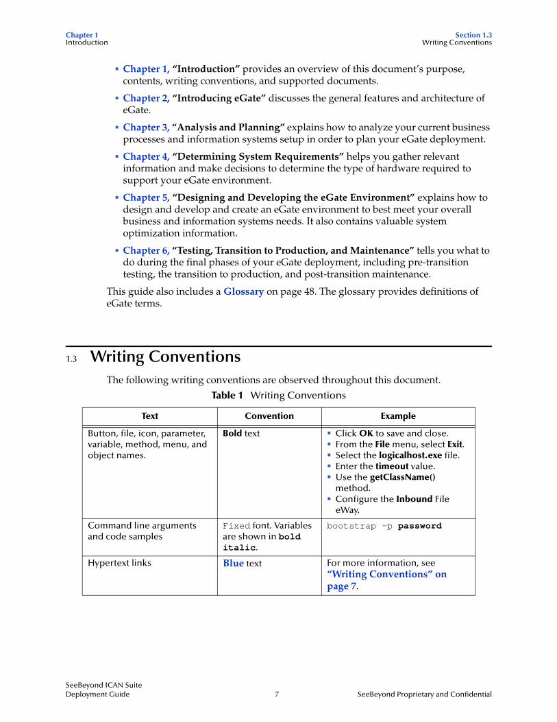
1.3 Writing ConventionsThe following writing conventions are observed throughout this document.
Table 1 Writing Conventions
Text Convention Example
Button, file, icon, parameter, variable, method, menu, and object names.
Bold text ! Click OK to save and close.! From the File menu, select Exit.! Select the logicalhost.exe file.! Enter the timeout value.! Use the getClassName()
method.! Configure the Inbound File
eWay.
Command line arguments and code samples
Fixed font. Variables are shown in bold italic.
bootstrap -p password
Hypertext links Blue text For more information, see “Writing Conventions” on page 7.
SeeBeyond ICAN Suite Deployment Guide 7 SeeBeyond Proprietary and Confidential
Chapter 1 Section 1.4Introduction Supporting Documents
Additional Conventions
Windows Systems
For the purposes of this guide, references to “Windows” will apply to Microsoft Windows Server 2003, Windows XP, and Windows 2000.
Path Name Separator
This guide uses the backslash (“\“) as the separator within path names. If you are working on a UNIX system, please make the appropriate substitutions.
1.4 Supporting DocumentsFor more information about eGate, refer to the following documents:
! eGate Integrator Installation Guide
! eGate Integrator Tutorial
! eGate Integrator User’s Guide
! SeeBeyond ICAN Suite Primer
Refer to the SeeBeyond Integrated Composite Application Networks Suite Primer for a complete list of eGate-related documentation.
SeeBeyond ICAN Suite Deployment Guide 8 SeeBeyond Proprietary and Confidential
Chapter 2
Introducing eGate
This chapter gives a general overview of the eGate, including system descriptions, general operation, and basic features.
In this chapter
! “About eGate” on page 9
! “eGate Architecture” on page 10
2.1 About eGateThe SeeBeyond eGate Integrator 5.0 system runs on a distributed and open architecture that enables components to reside on different servers/workstations within a global network. Depending on the communication protocols and adapters you choose, eGate can communicate with and link multiple applications and databases across a variety of operating systems.
2.1.1 System VersatilityeGate performs effectively with a wide variety of hardware, message standards, operating systems, databases, and communication protocols in both real-time and scheduled integration modes. eGate bridges older and newer systems to create a centrally managed, intelligent, unified enterprise. This gives administrators the flexibility to incorporate best-of-breed technology into their business strategy, without any need to uproot older information technology (IT) investments. eGate delivers a high level of precision, accuracy, and flexibility in the definition, detection, and control of cross-application business processes.
2.1.2 Project OrganizationAn eGate system is constructed with the Enterprise Designer, which is the primary graphical user interface (GUI) for configuring eGate. The components of an eGate system are organized into Connectivity Maps. A Connectivity Map is a configuration unit that contains all of the modules and parameters that control, route, and transform data as it travels through the eGate system. A Connectivity Map also maintains the relationships between the components, including the publish/subscribe information that serves as the bus of the data transportation process.
SeeBeyond ICAN Suite Deployment Guide 9 SeeBeyond Proprietary and Confidential
Chapter 2 Section 2.2Introducing eGate eGate Architecture
2.2 eGate ArchitectureThe eGate platform implements a transparent architecture that is well-suited for distributed computing environments. This means that the various components of an eGate system do not have to reside on the same machine. Instead, they can be distributed across several different machines in the network.
2.2.1 Runtime ComponentseGate includes dynamic, flexible, and distributable runtime components with the following strengths:
! Connectivity
! Transformation
! Business Logic
! Persistence
! Maintainability
! Efficiency
! Monitoring
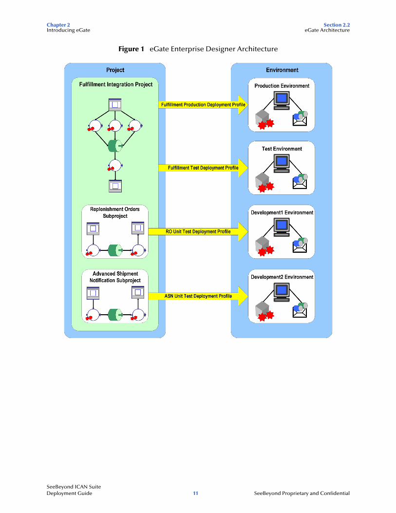
2.2.2 Enterprise DesignerThe Enterprise Designer includes the following graphical user interfaces (GUIs) to assist you in the development of an eGate Project:
! Enterprise Explorer
! Connectivity Map
! Object Type Definition Wizards and Editor
! Collaboration Definition Wizards and Editors
! Deployment Window
! Environment Window
! Impact Analyzer
! Version Control
Refer to Figure 1 for an overview of the Project creation process. See the eGate Integrator User’s Guide for more information about each GUI.
SeeBeyond ICAN Suite Deployment Guide 10 SeeBeyond Proprietary and Confidential
Chapter 2 Section 2.2Introducing eGate eGate Architecture
Figure 1 eGate Enterprise Designer Architecture
SeeBeyond ICAN Suite Deployment Guide 11 SeeBeyond Proprietary and Confidential
Chapter 3
Analysis and Planning
This chapter explains how to analyze your current business systems and processes in order to plan the optimum eGate design and deployment to meet your stated requirements.
In this chapter
! “Introduction: Analysis and Planning” on page 12
! “Gathering Information” on page 13
! “Analyzing Your Requirements” on page 14
! “Planning Your Deployment” on page 18
3.1 Introduction: Analysis and PlanningDeploying eGate requires completion of the following phases:
1 Analysis of requirements
2 Deployment planning
3 System design and development
4 Pre-transition testing
5 Transition to production
6 Post-transition maintenance
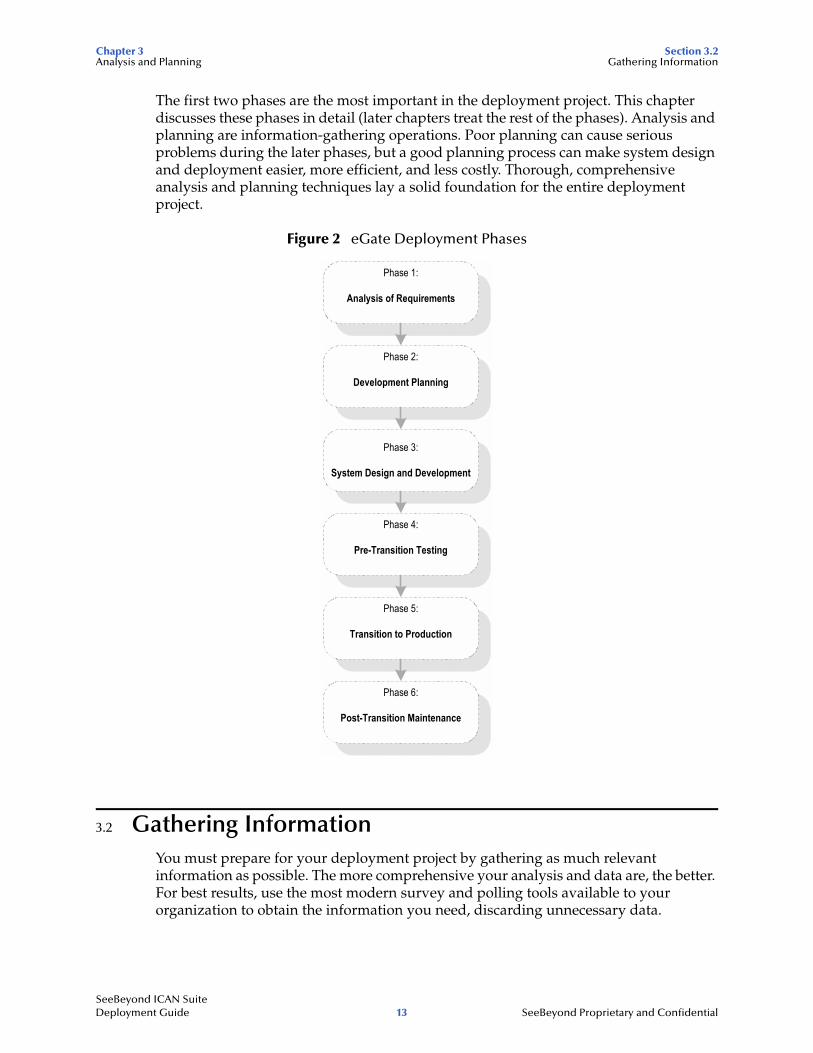
Figure 2 on page 13 shows a diagram of these six deployment phases. This chapter explains the first two phases, which are:
! Analysis of requirements phase: This deployment guide seeks to give you a road map of how to deploy eGate. First, to use a road map, you have to know where you are (analysis) and where you are going (planning). In other words, find out everything you can about your information system setup and business processes. Then, you can decide what information systems and business process needs you want eGate to meet.
! Deployment planning phase: Deployment begins when you plan out and schedule how, in view of your analysis information and allocated resources, you want to implement your eGate environment. During this phase, you set up the operation procedure and schedule for the entire deployment project.
SeeBeyond ICAN Suite Deployment Guide 12 SeeBeyond Proprietary and Confidential
Chapter 3 Section 3.2Analysis and Planning Gathering Information
The first two phases are the most important in the deployment project. This chapter discusses these phases in detail (later chapters treat the rest of the phases). Analysis and planning are information-gathering operations. Poor planning can cause serious problems during the later phases, but a good planning process can make system design and deployment easier, more efficient, and less costly. Thorough, comprehensive analysis and planning techniques lay a solid foundation for the entire deployment project.
Figure 2 eGate Deployment Phases
3.2 Gathering InformationYou must prepare for your deployment project by gathering as much relevant information as possible. The more comprehensive your analysis and data are, the better. For best results, use the most modern survey and polling tools available to your organization to obtain the information you need, discarding unnecessary data.
Phase 1:
Analysis of Requirements
Phase 2:
Development Planning
Phase 3:
System Design and Development
Phase 4:
Pre-Transition Testing
Phase 5:
Transition to Production
Phase 6:
Post-Transition Maintenance
SeeBeyond ICAN Suite Deployment Guide 13 SeeBeyond Proprietary and Confidential
Chapter 3 Section 3.3Analysis and Planning Analyzing Your Requirements
Information-gathering Tools
Use the following tools to assemble your deployment research:
! Research and interviews
! Surveys
3.2.1 Research and InterviewsThese methods are the time-honored, traditional ways of gathering information. Use them as diligently as a college student writing a term paper. Your company has reams of paper, cabinets full of files, and databases overflowing with useful information, from management directives to marketing papers to MIS memoranda. Much important deployment information exists here, provided that you make good use of it.
Interview and talk to the employees of your organization. Find out what they do and what their information systems needs are. Of course, input from relevant management and MIS people is necessary, but do not forget marketing employees, secretaries, and anyone else in touch with data flow needs. You want to put together a complete picture of your organization’s current and future information systems/business process requirements.
SeeBeyond’s Professional Services department can help you in answering specific questions on how to gather data and what kinds of data are relevant for your own deployment project. You can utilize this resource, as necessary.
3.2.2 SurveysFormal surveys are excellent tools for getting information. Surveys allow you to organize your own thoughts and processes, as well as helping to gather the desired information from others. There is a lot of helpful literature available on creating, giving, and analyzing polls and surveys. Reading some of this literature can provide a helpful background for doing these tasks.
3.3 Analyzing Your RequirementsIn gathering and analyzing information on your eGate needs, you must first know what kind of information you need. Remember that eGate links to your current networks, business systems, and applications together into a single, seamless information system. The purpose of this system is to facilitate your current and future business process needs. In other words, in as much detail as possible, find out where you are and what you need.
Examining Your Needs
During the analysis of requirements phase, you examine your needs and define the properties that the system must possess to meet those needs. Also, you identify system constraints and performance requirements. Define what functions you want the deployed system to perform but not how the functions work (this task happens during
SeeBeyond ICAN Suite Deployment Guide 14 SeeBeyond Proprietary and Confidential
Chapter 3 Section 3.3Analysis and Planning Analyzing Your Requirements
the design and development phase; see Chapter 5 “Designing and Developing the eGate Environment”).
This section tells you what kinds of information you need to gather to facilitate your eGate deployment, by posing a series of relevant questions. Make sure you answer all these questions as thoroughly and correctly as possible and discard any information that does not help you in answering them.
These questions fall into the following general categories:
! System-specific
! Operation and performance
! Personnel and training
! Business planning
Keep in mind that examples given in this section are general and are only meant to start you thinking in the right direction. You must begin by assembling general information on your needs, categorize that information, and expand on it by filling in necessary details to fully explain each category. See Chapter 5 for more detailed examples of specific information you must put together.
3.3.1 System-specific NeedsThese needs are the basic information systems, network, and database-related requirements you want the eGate system to meet. Determine your system-specific needs by asking the following questions:
What existing systems do we need to connect?
Create a complete picture of your current information system setup. Include applications, networks, systems, platforms, and outside information pathways.
Example: An Intel PC LAN with Windows XP network connecting workgroups with office applications, a UNIX system with an Oracle database containing customer information, and UNIX system with IMS tracking financial transactions.
How do we want to do the connecting?
Find out how you want your various systems to talk to each other (communication protocols), which systems must be linked, and the direction of communication.
Example: We have systems A, B, C, and D. Systems A and B use TCP/IP, C uses SNA, and D uses SAP. All systems must talk to each other except system D which only needs to communicate with A. All communication in all systems is two-way, except that system C only needs to receive information from the others and not send it.
What are our data requirements?
What types of data do you use, how much, and when?
Example: Our system uses HL7 and X12 data types. On average, our system needs to move about 100,000 messages per day at about 5 MB per message, with 90 percent of that data moving between 8 a.m. and 5 p.m. every Monday through Friday. Peak data loads are generally between 2 and 4 p.m. on weekdays (60 percent of volume).
SeeBeyond ICAN Suite Deployment Guide 15 SeeBeyond Proprietary and Confidential
Chapter 3 Section 3.3Analysis and Planning Analyzing Your Requirements
What are our system/hardware limitations and constraints?
Installing eGate requires that you have the necessary hardware and operating system (OS) software and purchase (and install if necessary) additional hardware and software to contain eGate. Do you want UNIX or Windows? What is your budget for additional hardware and software? Do you have any space limitations in the area where this hardware will reside?
Example: We use Solaris UNIX servers for our large scale systems. We will need to plan to purchase Windows client PCs for each of our system developers who will be designing eGate Projects using the eGate Enterprise Designer.
Planning for hardware needs requires special considerations, for example, how many systems you need, memory (RAM) required, the number of CPUs you need, and total disk space. Chapter 4 discusses in detail how to analyze and plan for these additional system requirements.
3.3.2 Operation and Performance NeedsDo you have any specific system operation and performance issues? Now is the time to discover, organize, and itemize them by asking the following questions:
What are our system performance requirements?
Ultimate system performance comes down to a trade-off between speed and maintainability. This fact is true overall, as well as being true for the operation of individual system component operations. You must prioritize these needs specifically.
Example: Customer databases must be totally accurate and detailed because the information is often used and vital to the company. Detailed maintenance of this data is more important than speed of processing. However, our moment-by-moment stock quotations have to be fast and up-to-the minute. Maintainability here is negligible because this data changes so fast that long-term retrieval is not an issue.
What are our internal security requirements?
eGate has access security, that is, special features allowing only certain persons to log on to the system and different persons to have specific privileges after the log on.
Example: The company only allows five people to log on to the system: one with system administrator privileges, two with operator privileges, and two with monitor privileges.
What are our error-handling and data validation requirements?
How, when, and where in the system does the customer require data to be error checked and validated? Keep in mind that processing speed decreases as checking instances and the detail of error checking increases.
Example: All data passing through our eGate must be validated to the most thorough extent possible. To facilitate this process, we compiled a complete list of all different data types that require validation.
SeeBeyond ICAN Suite Deployment Guide 16 SeeBeyond Proprietary and Confidential
Chapter 3 Section 3.3Analysis and Planning Analyzing Your Requirements
3.3.3 Personnel and Training NeedsDeploying eGate may require some expanded personnel needs, so you must consider the following questions:
Do we have personnel trained and able to deploy the system?
Deploying eGate does require some training of current personnel and may require the hiring of additional persons, depending on the size of the system you are planning and implementing. The use of SeeBeyond Professional Services staff can often be the most cost effective way to deploy your eGate implementation.
Example: We need two resources to deploy and later operate the new system. One new person must be hired. All three must attend the basic eGate class and introduction to Java class (both offered by SeeBeyond) and one must attend the basic and the advanced class. The new hire must be thoroughly trained in UNIX (not offered by SeeBeyond).
Do we have personnel trained and able to maintain the system after deployment?
Post-transition maintenance of eGate may also require additional personnel and training.
Example: In addition to personnel hired to deploy the system, we must train one additional resource for long-term system maintenance.
3.3.4 Business Planning NeedseGate can help you facilitate and improve your overall business processes. Assess your needs in these areas by asking the following questions:
What are our record-keeping and documentation needs?
Make sure you set up a system for documenting your eGate operation.
Example: We must put a new methodology in place to document and diagram the total operation of eGate. In addition we must keep complete records on that operation.
How do we create a deployment road map?
Plan your deployment well. Choose a deployment project team (for a small deployment, one person could do this task) to carry out the project, and make sure you document your plan in writing. Flowcharts and system diagrams are definitely helpful (see “Planning Your Deployment” on page 18).
SeeBeyond ICAN Suite Deployment Guide 17 SeeBeyond Proprietary and Confidential
Chapter 3 Section 3.4Analysis and Planning Planning Your Deployment
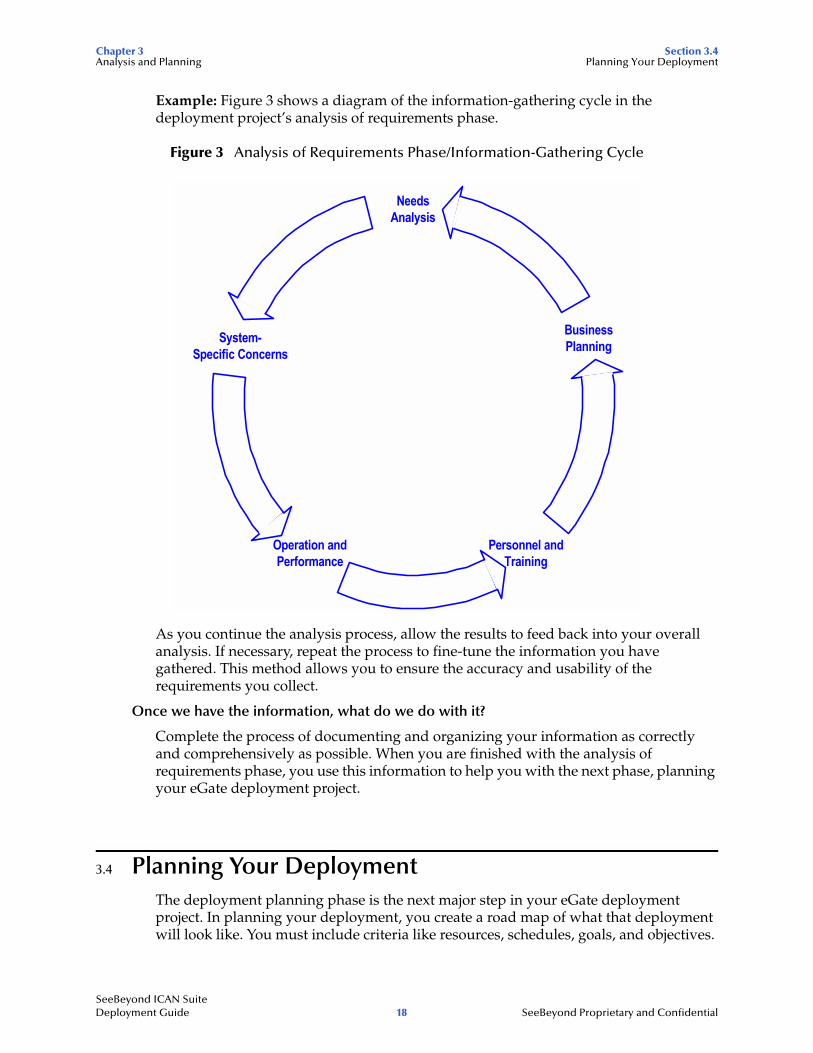
Example: Figure 3 shows a diagram of the information-gathering cycle in the deployment project’s analysis of requirements phase.
Figure 3 Analysis of Requirements Phase/Information-Gathering Cycle
As you continue the analysis process, allow the results to feed back into your overall analysis. If necessary, repeat the process to fine-tune the information you have gathered. This method allows you to ensure the accuracy and usability of the requirements you collect.
Once we have the information, what do we do with it?
Complete the process of documenting and organizing your information as correctly and comprehensively as possible. When you are finished with the analysis of requirements phase, you use this information to help you with the next phase, planning your eGate deployment project.
3.4 Planning Your DeploymentThe deployment planning phase is the next major step in your eGate deployment project. In planning your deployment, you create a road map of what that deployment will look like. You must include criteria like resources, schedules, goals, and objectives.
NeedsAnalysis
BusinessPlanning
Personnel andTraining
Operation andPerformance
System-Specific Concerns
SeeBeyond ICAN Suite Deployment Guide 18 SeeBeyond Proprietary and Confidential
Chapter 3 Section 3.4Analysis and Planning Planning Your Deployment
The primary purpose of this phase is to initiate the project, define the integrated system to be developed, create top-level design documents, and create a formal project plan or road map.
In creating your deployment road map, you provide a detailed description of the integrated eGate to be developed. This plan serves the following primary purposes:
! Designing what your future system looks like
! Showing you the resource allocation needed to implement the design
If analysis is finding out where you are, planning tells you where you want to go and how to get there. You can obtain help, when necessary, from SeeBeyond’s Professional Services and other SeeBeyond representatives. Thorough and comprehensive planning helps to ensure a smooth-running and satisfactory deployment project.
The major steps in deployment planning are:
! Setting up overall objectives
! Identifying and scheduling tasks
! Determining when objectives are met
3.4.1 Setting Up Overall ObjectivesThis step of the deployment planning phase entails the following operations:
1 Achieve a consensus on the implemented eGate’s overall functionality and scope by taking the following steps:
" Set up organized technical and functional teams or roles to handle individual phases and aspects of the deployment.
Note: For a small deployment, one person could handle the tasks of a team.
" Ensure that the system’s functionality is clearly stated and agreed upon.
" Document the functionality and scope of the project based on analysis information, as well as match this information against the scope of the project as stated in the “Approved Proposal.”
" Resolve any differences between the “Approved Proposal” scope and your prepared analysis and requirements information (see “Analyzing Your Requirements” on page 14), if necessary.
2 Create a general model of what the system will do. This model serves the following purposes:
" Serves as the foundation architectural plan for all eGate design (see Chapter 5 “Designing and Developing the eGate Environment”).
" Consists of diagrams and supporting documentation that represents the design strategy for any required eGate interfaces.
3 Set up a design and development team or role and provide this team with an understanding of the application domain. Also provide them with approved, clearly stated, top-level design documentation of requirements for eGate domain.
SeeBeyond ICAN Suite Deployment Guide 19 SeeBeyond Proprietary and Confidential
Chapter 3 Section 3.4Analysis and Planning Planning Your Deployment
4 At this point, the groups and persons meeting together must formulate a basis of validation of the final product during acceptance testing (see Chapter 6 “Testing, Transition to Production, and Maintenance”). This validation process includes the testing required to validate the functionality of the system and that it works as stated in the “Approved Proposal.”
3.4.2 Identifying and Scheduling TasksThis step of the deployment planning phase includes:
! Deployment initiation steps
! Creation of deployment documents
Beginning Deployment
Begin the deployment project via the following actions:
! Hold a Project Kick-off Meeting: This meeting identifies all members of the deployment project team. The analysis tasks and responsibilities assigned to each resource will also be identified. The purpose of this task is to outline the reporting structure for the project and identify whom the Project Manager communicates with to ensure that other tasks in the project are being completed as planned. In addition, documentation standards and the project reporting structure are established at this time.
! Ensure Software and Hardware Installation: The purpose of this task is to ensure that your hardware and software is in place and ready for eGate installation. This process includes ensuring that eGate software is fully supported on your hardware platform and operating system and that the software has been shipped.
! Complete Installation Test, Installation, and Checklist: eGate installation task is completed during the deployment planning phase to ensure there are no issues with your technical environment. You can use a deployment checklist to detail the exact hardware and operating systems where the installation will be performed. This task includes the following steps:
" The total eGate environment must be installed and tested. The deployment checklist is updated to identify what items were completed and document outstanding issues that may have kept any items from being completed.
" The production, training, and test (pre-production) hardware, software and network requirements (current and planned) are identified and verified.
" The end-to-end communications with your other systems are also tested to ensure that communications are set up correctly and systems are exchanging messages correctly according to the communication protocol being invoked.
" Any communications with other businesses or trading partners are tested in the same way.
! Establish the Change Management Process: A critical factor through all phases of the project is change management. Change management identifies and track all changes for a project that depart from the original deployment plan. All changes
SeeBeyond ICAN Suite Deployment Guide 20 SeeBeyond Proprietary and Confidential
Chapter 3 Section 3.4Analysis and Planning Planning Your Deployment
must be identified and tracked because many small changes can and will impact a deployment project in the same way as a more easily identifiable large-scale change. Tracking all changes allows the project manager to plan and control a project and keep track of all changes in the project’s scope.
Deployment Documents
You must document the deployment project. This step requires that you create the following documents:
! Preparing the Deployment Project Plan: This document lists a set of tasks for establishing a baseline reference plan. It is your road map for the deployment project. The roles and responsibilities of each organization, schedule of tasks, and any estimates must be defined in this plan.
It is best that this plan be as detailed as possible. Any project risks must be assessed and documented. Your necessary resources are budgeted using this plan (or validated if you have already created a budget).
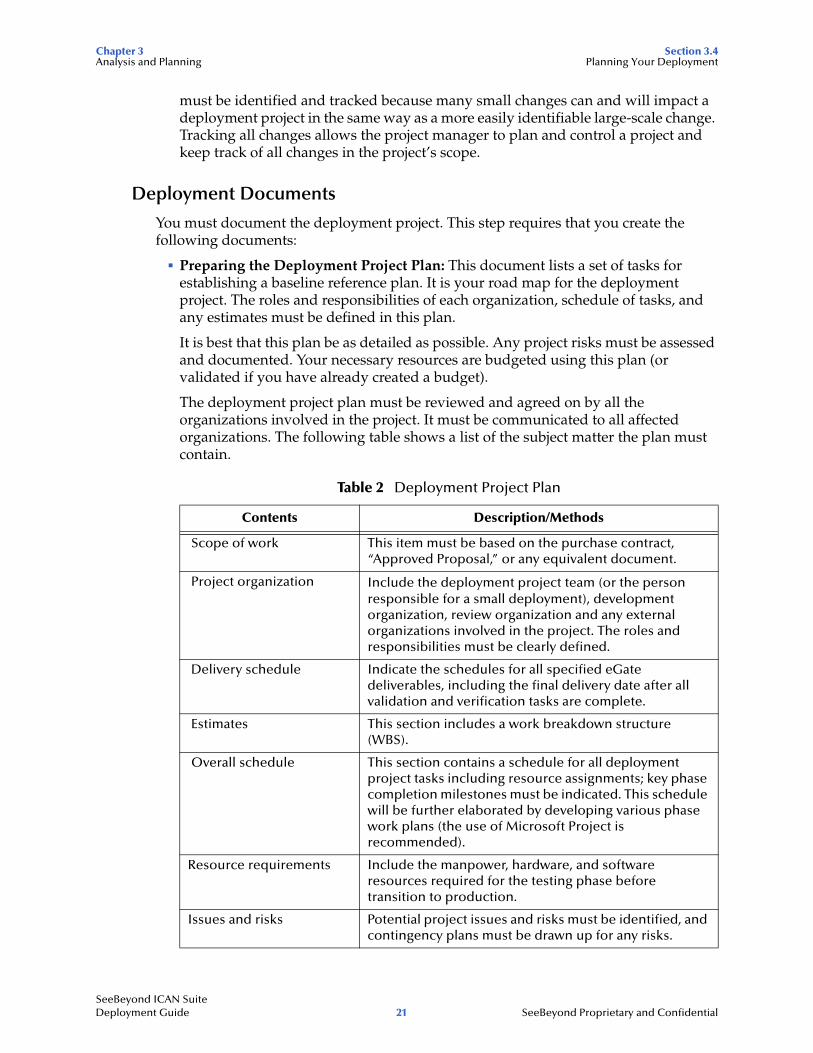
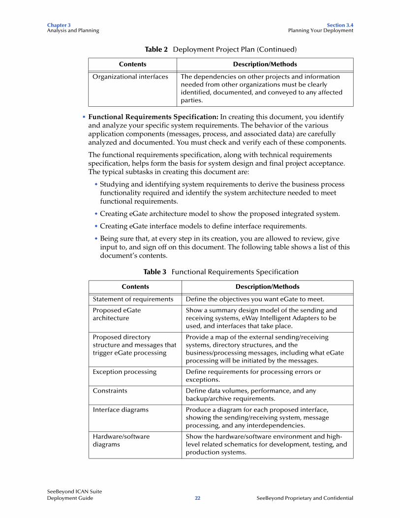
The deployment project plan must be reviewed and agreed on by all the organizations involved in the project. It must be communicated to all affected organizations. The following table shows a list of the subject matter the plan must contain.
Table 2 Deployment Project Plan
Contents Description/Methods
Scope of work This item must be based on the purchase contract, “Approved Proposal,” or any equivalent document.
Project organization Include the deployment project team (or the person responsible for a small deployment), development organization, review organization and any external organizations involved in the project. The roles and responsibilities must be clearly defined.
Delivery schedule Indicate the schedules for all specified eGate deliverables, including the final delivery date after all validation and verification tasks are complete.
Estimates This section includes a work breakdown structure (WBS).
Overall schedule This section contains a schedule for all deployment project tasks including resource assignments; key phase completion milestones must be indicated. This schedule will be further elaborated by developing various phase work plans (the use of Microsoft Project is recommended).
Resource requirements Include the manpower, hardware, and software resources required for the testing phase before transition to production.
Issues and risks Potential project issues and risks must be identified, and contingency plans must be drawn up for any risks.
SeeBeyond ICAN Suite Deployment Guide 21 SeeBeyond Proprietary and Confidential
Chapter 3 Section 3.4Analysis and Planning Planning Your Deployment
! Functional Requirements Specification: In creating this document, you identify and analyze your specific system requirements. The behavior of the various application components (messages, process, and associated data) are carefully analyzed and documented. You must check and verify each of these components.
The functional requirements specification, along with technical requirements specification, helps form the basis for system design and final project acceptance. The typical subtasks in creating this document are:
" Studying and identifying system requirements to derive the business process functionality required and identify the system architecture needed to meet functional requirements.
" Creating eGate architecture model to show the proposed integrated system.
" Creating eGate interface models to define interface requirements.
" Being sure that, at every step in its creation, you are allowed to review, give input to, and sign off on this document. The following table shows a list of this document’s contents.
Organizational interfaces The dependencies on other projects and information needed from other organizations must be clearly identified, documented, and conveyed to any affected parties.
Table 3 Functional Requirements Specification
Contents Description/Methods
Statement of requirements Define the objectives you want eGate to meet.
Proposed eGate architecture
Show a summary design model of the sending and receiving systems, eWay Intelligent Adapters to be used, and interfaces that take place.
Proposed directory structure and messages that trigger eGate processing
Provide a map of the external sending/receiving systems, directory structures, and the business/processing messages, including what eGate processing will be initiated by the messages.
Exception processing Define requirements for processing errors or exceptions.
Constraints Define data volumes, performance, and any backup/archive requirements.
Interface diagrams Produce a diagram for each proposed interface, showing the sending/receiving system, message processing, and any interdependencies.
Hardware/software diagrams
Show the hardware/software environment and high-level related schematics for development, testing, and production systems.
Table 2 Deployment Project Plan (Continued)
Contents Description/Methods
SeeBeyond ICAN Suite Deployment Guide 22 SeeBeyond Proprietary and Confidential
Chapter 3 Section 3.4Analysis and Planning Planning Your Deployment
The general design model provided by this document forms the starting basis of the next deployment step, the system design and development phase. See Chapter 5 for details on how to use this model as the foundation for your complete eGate architecture.
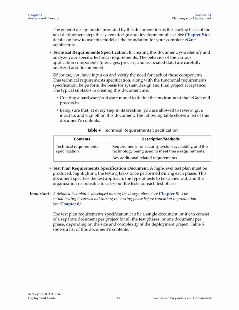
! Technical Requirements Specification: In creating this document, you identify and analyze your specific technical requirements. The behavior of the various application components (messages, process, and associated data) are carefully analyzed and documented.
Of course, you have input on and verify the need for each of these components. This technical requirements specification, along with the functional requirements specification, helps form the basis for system design and final project acceptance. The typical subtasks in creating this document are:
" Creating a hardware/software model to define the environment that eGate will process in.
" Being sure that, at every step in its creation, you are allowed to review, give input to, and sign off on this document. The following table shows a list of this document’s contents.
! Test Plan Requirements Specification Document: A high-level test plan must be produced, highlighting the testing tasks to be performed during each phase. This document specifies the test approach, the type of tests to be carried out, and the organization responsible to carry out the tests for each test phase.
Important: A detailed test plan is developed during the design phase (see Chapter 5). The actual testing is carried out during the testing phase before transition to production (see Chapter 6).
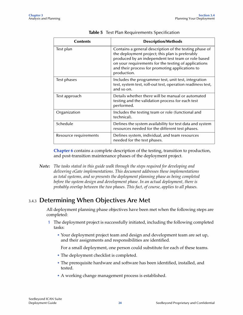
The test plan requirements specification can be a single document, or it can consist of a separate document per project for all the test phases, or one document per phase, depending on the size and complexity of the deployment project. Table 5 shows a list of this document’s contents.
Table 4 Technical Requirements Specification
Contents Description/Methods
Technical requirements specification
Requirements for security, system availability, and the technology being used to meet these requirements.
Any additional related requirements.
SeeBeyond ICAN Suite Deployment Guide 23 SeeBeyond Proprietary and Confidential
Chapter 3 Section 3.4Analysis and Planning Planning Your Deployment
Chapter 6 contains a complete description of the testing, transition to production, and post-transition maintenance phases of the deployment project.
Note: The tasks stated in this guide walk through the steps required for developing and delivering eGate implementations. This document addresses these implementations as total systems, and so presents the deployment planning phase as being completed before the system design and development phase. In an actual deployment, there is probably overlap between the two phases. This fact, of course, applies to all phases.
3.4.3 Determining When Objectives Are MetAll deployment planning phase objectives have been met when the following steps are completed:
1 The deployment project is successfully initiated, including the following completed tasks:
" Your deployment project team and design and development team are set up, and their assignments and responsibilities are identified.
For a small deployment, one person could substitute for each of these teams.
" The deployment checklist is completed.
" The prerequisite hardware and software has been identified, installed, and tested.
" A working change management process is established.
Table 5 Test Plan Requirements Specification
Contents Description/Methods
Test plan Contains a general description of the testing phase of the deployment project; this plan is preferably produced by an independent test team or role based on your requirements for the testing of applications and their process for promoting applications to production.
Test phases Includes the programmer test, unit test, integration test, system test, roll-out test, operation readiness test, and so on.
Test approach Details whether there will be manual or automated testing and the validation process for each test performed.
Organization Includes the testing team or role (functional and technical).
Schedule Defines the system availability for test data and system resources needed for the different test phases.
Resource requirements Defines system, individual, and team resources needed for the test phases.
SeeBeyond ICAN Suite Deployment Guide 24 SeeBeyond Proprietary and Confidential
Chapter 3 Section 3.4Analysis and Planning Planning Your Deployment
2 The deployment project plan has been completed, updated (if necessary), and approved by deployment project leadership and your management.
3 The functional, technical, and test plan requirements specifications are completed and approved by deployment project leadership and your management.
4 The deployment project leadership must review and approve the following requirements:
" Architecture design documents must be completed and approved.
" Test requirements must be identified, documented, and approved.
" All analysis information must be verified as detailed and accurate enough to predict the deployment’s cost and duration.
5 Any subsequent issues resulting in a change of the project scope and resources must be communicated and signed off, including approval by deployment project leadership and your management.
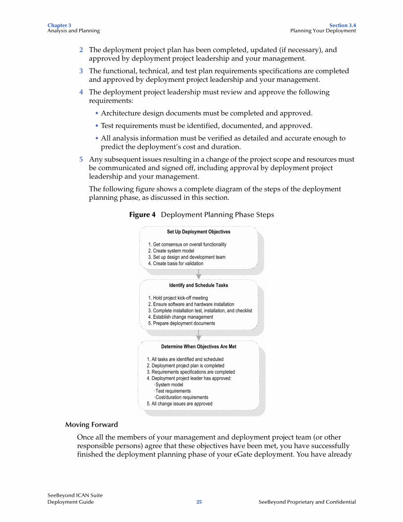
The following figure shows a complete diagram of the steps of the deployment planning phase, as discussed in this section.
Figure 4 Deployment Planning Phase Steps
Moving Forward
Once all the members of your management and deployment project team (or other responsible persons) agree that these objectives have been met, you have successfully finished the deployment planning phase of your eGate deployment. You have already
Set Up Deployment Objectives
1. Get consensus on overall functionality2. Create system model3. Set up design and development team4. Create basis for validation
Identify and Schedule Tasks
1. Hold project kick-off meeting2. Ensure software and hardware installation3. Complete installation test, installation, and checklist4. Establish change management5. Prepare deployment documents
Determine When Objectives Are Met
1. All tasks are identified and scheduled2. Deployment project plan is completed3. Requirements specifications are completed4. Deployment project leader has approved:
· System model· Test requirements· Cost/duration requirements
5. All change issues are approved
SeeBeyond ICAN Suite Deployment Guide 25 SeeBeyond Proprietary and Confidential
Chapter 3 Section 3.4Analysis and Planning Planning Your Deployment
created a complete deployment road map, the “deployment project plan,” along with some general designs for your completed system.
The rest of the chapters in this guide treat eGate deployment project under the following topics:
! Hardware Needs: An important part of planning for your system and deployment is how to determine your hardware requirements. If you need additional information on planning for and determining your system’s hardware requirements, see Chapter 4.
! System Design: For a discussion of the next phase of your deployment project, including system design architecture and development, see Chapter 5. In this phase, you broaden and fill in the details of the general designs you created during planning.
! Testing and Transition to Production: For a discussion of the testing, transition (go-live), and maintenance (fine-tuning) phases of your system deployment, see Chapter 6. These phases follow the system design and development phase.
SeeBeyond ICAN Suite Deployment Guide 26 SeeBeyond Proprietary and Confidential
Chapter 4
Determining System Requirements
This chapter offers guidelines to help you determine the system requirements for the deployment of eGate.
In this chapter
! “Introduction: System Requirements” on page 27
! “Initial Considerations” on page 27
! “Estimating Requirements” on page 28
! “System Requirements: Summary” on page 32
4.1 Introduction: System RequirementsThis chapter explains how to assess your needs for the following types of hardware:
! CPUs
! Hard disk space
! Random access memory (RAM)
There are many variables and factors to consider in order to adequately determine the hardware requirements for your particular system. As such, this discussion will be limited to issues as they relate directly to eGate.
This chapter does not consider networking topology, and does not address such issues as shared applications, how resources are distributed throughout a network, and how many workstations are included in the network. Furthermore, in the case of databases, it is assumed that each database management system is installed on a separate host. See Chapter 5 for details on these considerations.
4.2 Initial ConsiderationseGate merges traditional Enterprise Application Integration (EAI) and Business-to-Business (B2B) interactions into a multi-enterprise eBusiness system.
SeeBeyond ICAN Suite Deployment Guide 27 SeeBeyond Proprietary and Confidential
Chapter 4 Section 4.3Determining System Requirements Estimating Requirements
Depending on the number of external connections, the type of data being processed, and how the data is processed, the required resources can vary. Take the following points into account as you begin estimating your hardware requirements:
! Each eGate deployment is different. Obviously, this is true when custom systems and enhancements to existing systems are present. The configuration of each deployment is unique because there are varying numbers of components as well as variances in interconnectivity. Some components are bidirectional and complex, while others merely pass data through.
! In addition to differences in configuration, the computational requirements will differ both in scope and complexity. The high-performance architecture of eGate is net-centric, not server-centric, not client-centric, and not hub-based, which makes eGate highly flexible. It is this flexibility that makes predicting the general requirements of hardware a complex task.
! An eGate solution is distributed via run-time components and is platform-independent. System stability and redundancy are important considerations. Server requirements vary greatly, depending on the components resident on the server, the archiving requirements configured on the customer's system, and other factors.
! Instead of only referring to absolute minimum requirements, it is more meaningful to discuss the hardware needs of an installation in terms of recommendations. By using the methods set forth in this chapter, a system analyst can estimate the required resources for a given configuration, from a simple deployment to a complex deployment, and thereby define an initial recommendation. Once installed, eGate can be fine-tuned, both in terms of hardware and software, to optimize performance.
4.3 Estimating RequirementseGate has been deployed in an extremely wide variety of environments, from simple deployments of a single system with a single CPU to highly sophisticated configurations consisting of 64 CPUs that process one billion transactions per day.
4.3.1 Consideration FactorsBecause eGate is a general-purpose toolkit that is completely flexible in its deployment and configuration, estimating the processor requirements is a challenge. There are infinite possibilities and numerous factors with complex interactions that affect the estimations. Some of the factors are more critical than others, depending on the circumstances.
For example, the effect of limited RAM resources that create a paging/swapping situation could completely hide the effects of a complex OTD or a poorly written Collaboration. Some of the factors that affect performance in eGate are:
! CPU type and architecture
! CPU speed
SeeBeyond ICAN Suite Deployment Guide 28 SeeBeyond Proprietary and Confidential
Chapter 4 Section 4.3Determining System Requirements Estimating Requirements
! Presence of a CPU cache and its size
! Number of CPUs
! Physical memory size
! Swap size
! Disk subsystem, that is, bandwidth, latency, block size, RPM, seek time, and the presence and size of the cache
! Network bandwidth and load
! Number of external systems and their latencies in servicing messages and acknowledgements
! Complexity and amount of processing to be performed by each component
! Message volume, size, and distribution through the day
! Throughput and response-time requirements
! Complexity of messages, including the number of nodes and complexity of regular expressions
! Bundling of messages, that is, more than one logical record in one physical record
! Number of transitions between components for a given message (for example, moving data from an eWay to a topic/queue to an eWay or Collaboration)
! Amount of the implementation that can utilize parallel processing
! Other loads on the Logical Hosts (for example, queue cleanup schedules, backups, and other processes)
! Dispersion of solution across multiple CPUs and systems
! Number and architecture of eGate subcomponents participating in the Project
Not only are there more factors, but these factors need to be assessed for each Logical Host in a distributed eGate deployment.
4.3.2 General GuidelinesThere is no standard benchmark in the EAI industry like there is in the Database Management System (DBMS) industry, that is, the Transaction Processing Performance Council (TPC) benchmark. It is debatable whether a benchmark can ever be developed, which could accurately and reliably predict the processing requirement for a given integration implementation. This difficulty results from the number and complexity of factors that could affect performance. The resulting equation would be impractical to use because of the large number of parameters and their weights.
Because there are many areas in which the architecture can be tuned to achieve further performance gains, each time a new change is made, the performance characteristics may be different. Another problem is that any benchmarking equation would rely on other measures that are just as problematic, for example, measuring program complexity, lines of code (LOCs), or function points (FPs).
SeeBeyond ICAN Suite Deployment Guide 29 SeeBeyond Proprietary and Confidential
Chapter 4 Section 4.3Determining System Requirements Estimating Requirements
Pragmatic Approach
A more pragmatic approach is to start with a good base configuration as a development system and use that configuration to predict the processor requirements for a production system for your unique implementation. The minimum hardware requirements for a typical eGate configuration of 20 interfaces would be one of the following systems:
! Windows 2000/XP system running on dual Pentium 4-class 866-MHz CPUs
! eGate-supported UNIX system running on two 800MHz-to-2-GHz CPUs
! Both of the above requirements with 1 GB of RAM and 20 GB of hard disk space, preferably in a hardware chassis that supports more than two CPUs
The recommended methodology is to implement a representative number of interfaces (that exercise a good sample of the various data transformations and communication requirements of the implementation) on this system, run representative data files through the system, and record the CPU load. From these measures, you can project what the final production load will be and therefore the CPU requirement. Of course, the architecture can be tuned to achieve more efficiency using this same technique.
One of the advantages of eGate’s distributed-and-scalable architecture is that hardware does not need to be replaced but can be included in a multi-system implementation. Therefore, as processing requirements grow, you can easily add new hardware.
Factors to Consider
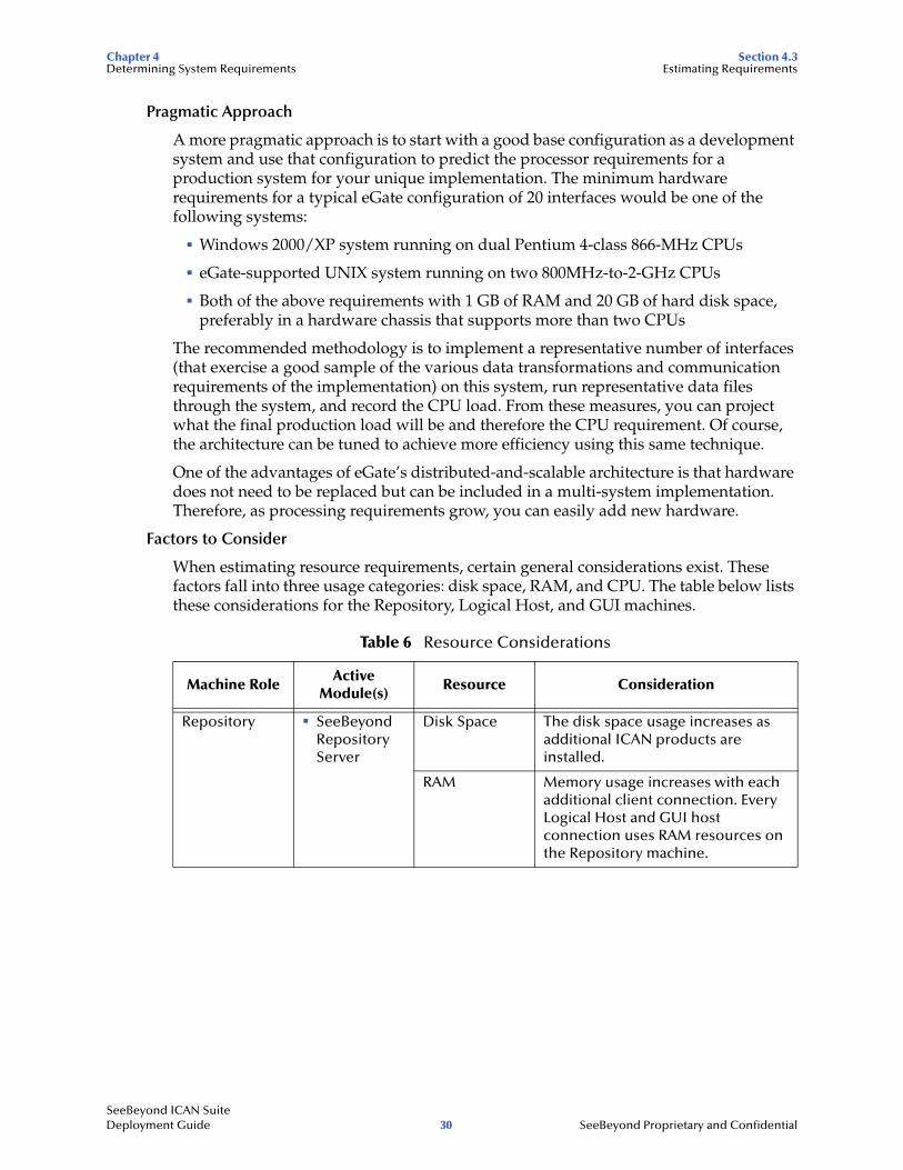
When estimating resource requirements, certain general considerations exist. These factors fall into three usage categories: disk space, RAM, and CPU. The table below lists these considerations for the Repository, Logical Host, and GUI machines.
Table 6 Resource Considerations
Machine RoleActive
Module(s)Resource Consideration
Repository ! SeeBeyond Repository Server
Disk Space The disk space usage increases as additional ICAN products are installed.
RAM Memory usage increases with each additional client connection. Every Logical Host and GUI host connection uses RAM resources on the Repository machine.
SeeBeyond ICAN Suite Deployment Guide 30 SeeBeyond Proprietary and Confidential
Chapter 4 Section 4.3Determining System Requirements Estimating Requirements
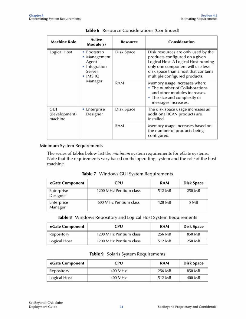
Minimum System Requirements
The series of tables below list the minimum system requirements for eGate systems. Note that the requirements vary based on the operating system and the role of the host machine.
Logical Host ! Bootstrap! Management
Agent! Integration
Server! JMS IQ
Manager
Disk Space Disk resources are only used by the products configured on a given Logical Host. A Logical Host running only one component will use less disk space than a host that contains multiple configured products.
RAM Memory usage increases when:! The number of Collaborations
and other modules increases.! The size and complexity of
messages increases.
GUI (development) machine
! Enterprise Designer
Disk Space The disk space usage increases as additional ICAN products are installed.
RAM Memory usage increases based on the number of products being configured.
Table 7 Windows GUI System Requirements
eGate Component CPU RAM Disk Space
Enterprise Designer
1200 MHz Pentium class 512 MB 250 MB
Enterprise Manager
600 MHz Pentium class 128 MB 5 MB
Table 8 Windows Repository and Logical Host System Requirements
eGate Component CPU RAM Disk Space
Repository 1200 MHz Pentium class 256 MB 850 MB
Logical Host 1200 MHz Pentium class 512 MB 250 MB
Table 9 Solaris System Requirements
eGate Component CPU RAM Disk Space
Repository 400 MHz 256 MB 850 MB
Logical Host 400 MHz 512 MB 400 MB
Table 6 Resource Considerations (Continued)
Machine RoleActive
Module(s)Resource Consideration
SeeBeyond ICAN Suite Deployment Guide 31 SeeBeyond Proprietary and Confidential
Chapter 4 Section 4.4Determining System Requirements System Requirements: Summary
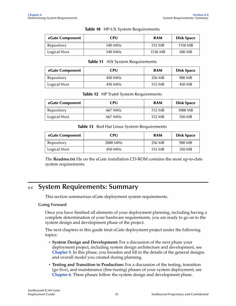
The Readme.txt file on the eGate installation CD-ROM contains the most up-to-date system requirements.
4.4 System Requirements: SummaryThis section summarizes eGate deployment system requirements.
Going Forward
Once you have finished all elements of your deployment planning, including having a complete determination of your hardware requirements, you are ready to go on to the system design and development phase of the project.
The next chapters in this guide treat eGate deployment project under the following topics:
! System Design and Development: For a discussion of the next phase your deployment project, including system design architecture and development, see Chapter 5. In this phase, you broaden and fill in the details of the general designs and overall model you created during planning.
! Testing and Transition to Production: For a discussion of the testing, transition (go-live), and maintenance (fine-tuning) phases of your system deployment, see Chapter 6. These phases follow the system design and development phase.
Table 10 HP-UX System Requirements
eGate Component CPU RAM Disk Space
Repository 540 MHz 512 MB 1150 MB
Logical Host 540 MHz 1536 MB 500 MB
Table 11 AIX System Requirements
eGate Component CPU RAM Disk Space
Repository 450 MHz 256 MB 900 MB
Logical Host 450 MHz 512 MB 450 MB
Table 12 HP Tru64 System Requirements
eGate Component CPU RAM Disk Space
Repository 667 MHz 512 MB 1000 MB
Logical Host 667 MHz 512 MB 350 MB
Table 13 Red Hat Linux System Requirements
eGate Component CPU RAM Disk Space
Repository 2000 MHz 256 MB 900 MB
Logical Host 450 MHz 512 MB 350 MB
SeeBeyond ICAN Suite Deployment Guide 32 SeeBeyond Proprietary and Confidential

Chapter 5
Designing and Developing the eGate Environment
This chapter explains how to design and develop a complete, functioning eGate based on your deployment analysis and planning.
In this chapter
! “An Overview of eGate Design” on page 33
! “Distributed Architecture Considerations” on page 35
! “Methodology Considerations” on page 38
5.1 An Overview of eGate DesignAfter the analysis and planning phase has been completed, your next major step is the system design and development phase. In many ways, this work is the heart of eGate deployment operation. During this phase, you flesh out the essential system architecture that implements your business plans and processes.
Designing the deployment of eGate environment requires a series of successive refinements applied to your initial summary plan (“Functional Requirements Specification” document as outlined in Table 3 on page 22). Your design must start with the broadest view of the system then proceed to the details.
Applying this top-down approach to deploying eGate environment results in the most effective application of its technology to the integration of your existing systems and applications. Total system design and development include the following basic steps:
! Planning general hardware configuration
! System design methodology
! Software installation and development
! System optimization
However, keep in mind that these steps are not necessarily an exact sequence. The entire design and development operation requires that you occasionally “back-track” to earlier steps and look forward to later steps, to implement the correct design refinements your system requires.
SeeBeyond ICAN Suite Deployment Guide 33 SeeBeyond Proprietary and Confidential
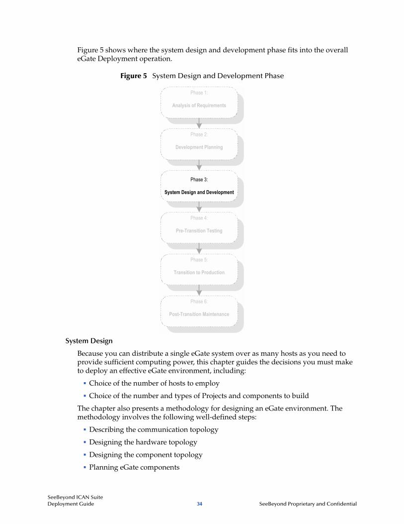
Figure 5 shows where the system design and development phase fits into the overall eGate Deployment operation.
Figure 5 System Design and Development Phase
System Design
Because you can distribute a single eGate system over as many hosts as you need to provide sufficient computing power, this chapter guides the decisions you must make to deploy an effective eGate environment, including:
! Choice of the number of hosts to employ
! Choice of the number and types of Projects and components to build
The chapter also presents a methodology for designing an eGate environment. The methodology involves the following well-defined steps:
! Describing the communication topology
! Designing the hardware topology
! Designing the component topology
! Planning eGate components
Phase 1:
Analysis of Requirements
Phase 2:
Development Planning
Phase 3:
System Design and Development
Phase 4:
Pre-Transition Testing
Phase 5:
Transition to Production
Phase 6:
Post-Transition Maintenance
SeeBeyond ICAN Suite Deployment Guide 34 SeeBeyond Proprietary and Confidential
Chapter 5 Section 5.2Designing and Developing the eGate Environment Distributed Architecture Considerations
! System optimization
System Development
Development proceeds after completion of design tasks and consists of a list of tasks to create each component of eGate. The section on development explains how you create the task list, including the completion order for the tasks.
5.2 Distributed Architecture ConsiderationsThe power of eGate lies in its fundamental design that includes:
! Distributed architecture
! Central management of computing
This section explains eGate’s distributed network architecture and how to take advantage of its specific features in your deployment.
5.2.1 Distributed Architecture in eGate: OverviewA common view of software systems starts with a box representing a computer host. Programs or processes are added to the computer host and are represented as smaller boxes inside the bigger box.
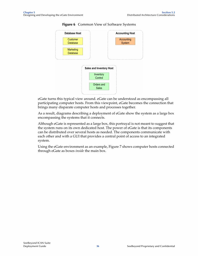
Multiple software systems are typically spread out over several physical hosts with no relationship or connection between the hosts. Figure 6 shows the conceptual relationship among several different software systems that are commonly built to support business needs.
While it is possible to connect many different types of systems such as those in Figure 6, it is inconvenient and costly to manage the connections without a central point of access.
In addition, economies of scale gained through reusable components are unlikely to exist in the typical hub-and-spoke architecture that these types of systems require.
SeeBeyond ICAN Suite Deployment Guide 35 SeeBeyond Proprietary and Confidential
Chapter 5 Section 5.2Designing and Developing the eGate Environment Distributed Architecture Considerations
Figure 6 Common View of Software Systems
eGate turns this typical view around. eGate can be understood as encompassing all participating computer hosts. From this viewpoint, eGate becomes the connection that brings many disparate computer hosts and processes together.
As a result, diagrams describing a deployment of eGate show the system as a large box encompassing the systems that it connects.
Although eGate is represented as a large box, this portrayal is not meant to suggest that the system runs on its own dedicated host. The power of eGate is that its components can be distributed over several hosts as needed. The components communicate with each other and with a GUI that provides a central point of access to an integrated system.
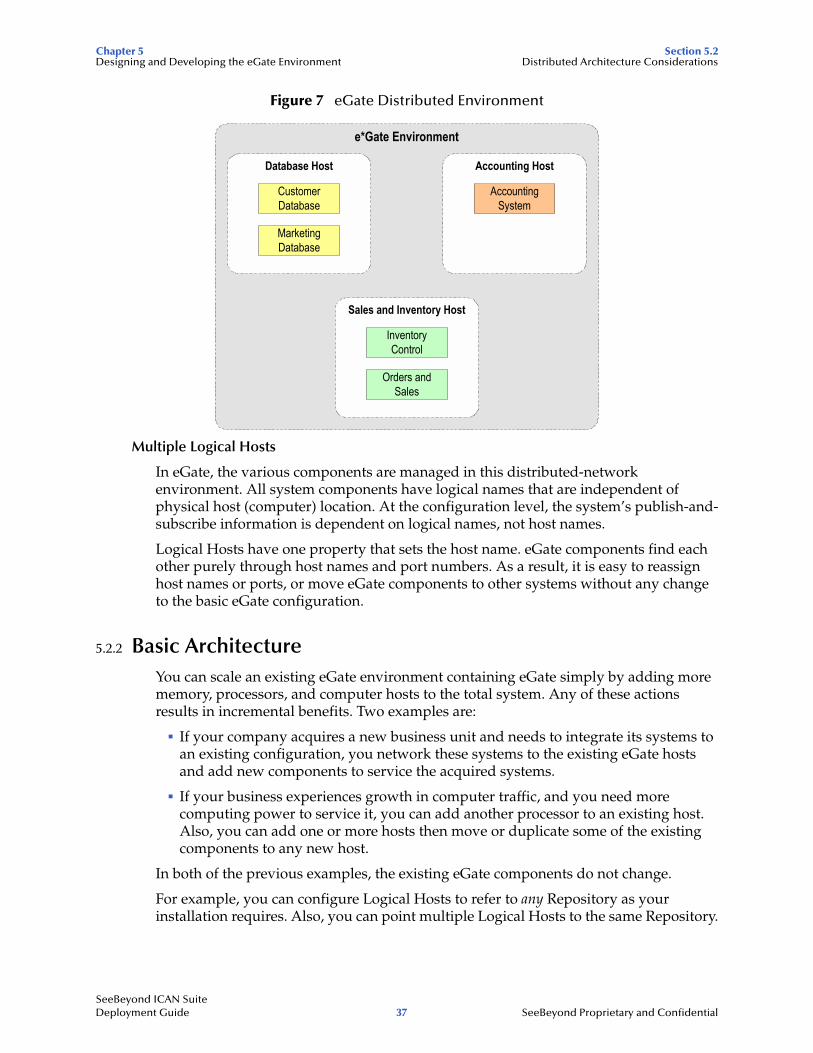
Using the eGate environment as an example, Figure 7 shows computer hosts connected through eGate as boxes inside the main box.
Accounting Host
AccountingSystem
Database Host
CustomerDatabase
MarketingDatabase
Sales and Inventory Host
InventoryControl
Orders andSales
SeeBeyond ICAN Suite Deployment Guide 36 SeeBeyond Proprietary and Confidential
Chapter 5 Section 5.2Designing and Developing the eGate Environment Distributed Architecture Considerations
Figure 7 eGate Distributed Environment
Multiple Logical Hosts
In eGate, the various components are managed in this distributed-network environment. All system components have logical names that are independent of physical host (computer) location. At the configuration level, the system’s publish-and-subscribe information is dependent on logical names, not host names.
Logical Hosts have one property that sets the host name. eGate components find each other purely through host names and port numbers. As a result, it is easy to reassign host names or ports, or move eGate components to other systems without any change to the basic eGate configuration.
5.2.2 Basic ArchitectureYou can scale an existing eGate environment containing eGate simply by adding more memory, processors, and computer hosts to the total system. Any of these actions results in incremental benefits. Two examples are:
! If your company acquires a new business unit and needs to integrate its systems to an existing configuration, you network these systems to the existing eGate hosts and add new components to service the acquired systems.
! If your business experiences growth in computer traffic, and you need more computing power to service it, you can add another processor to an existing host. Also, you can add one or more hosts then move or duplicate some of the existing components to any new host.
In both of the previous examples, the existing eGate components do not change.
For example, you can configure Logical Hosts to refer to any Repository as your installation requires. Also, you can point multiple Logical Hosts to the same Repository.
e*Gate Environment
Accounting Host
AccountingSystem
Database Host
CustomerDatabase
MarketingDatabase
Sales and Inventory Host
InventoryControl
Orders andSales
SeeBeyond ICAN Suite Deployment Guide 37 SeeBeyond Proprietary and Confidential
Chapter 5 Section 5.3Designing and Developing the eGate Environment Methodology Considerations
Project and Component Organization
eGate components are organized into Projects. A Project is a configuration scheme that contains all the modules and configuration parameters that control, route, and transform data as it travels through the overall system.
A Project also maintains the relationships between its internal components, including the publish/subscribe information that is at the heart of eGate’s data transportation process.
The number, design, location, and component makeup of your Projects is a function of your overall design methodology, as explained under “Methodology Considerations” on page 38.
5.3 Methodology ConsiderationsMethodology means the ways or methods to figure out how to design eGate to best meet your business and information system needs.
5.3.1 What is Topology?Topology refers to the pattern of connections between interrelated objects. Topology considers only relationships between objects and ignores the location of the objects.
Because eGate is centrally managed, the location of a Logical Host is insignificant in designing the system. Understanding the meaning of topology is important in providing a conceptual framework for discussing design considerations for your total system.
Elements of Topology
A topology exists between the following elements:
Computer Systems Related by CommunicationThis is a data-flow topology because the only concern is which system is communicating with which other system. Communications topology is therefore only logical because it has no reality in hardware.
Computer Hosts Related by Physical Network ConnectionsThis is a hardware topology because it concerns the relationship between physical computer hosts.
eGate Components Related by Publication and SubscriptionThis is a component topology because it concerns the pub/sub relationship between components.
SeeBeyond ICAN Suite Deployment Guide 38 SeeBeyond Proprietary and Confidential
Chapter 5 Section 5.3Designing and Developing the eGate Environment Methodology Considerations
Sample Topologies
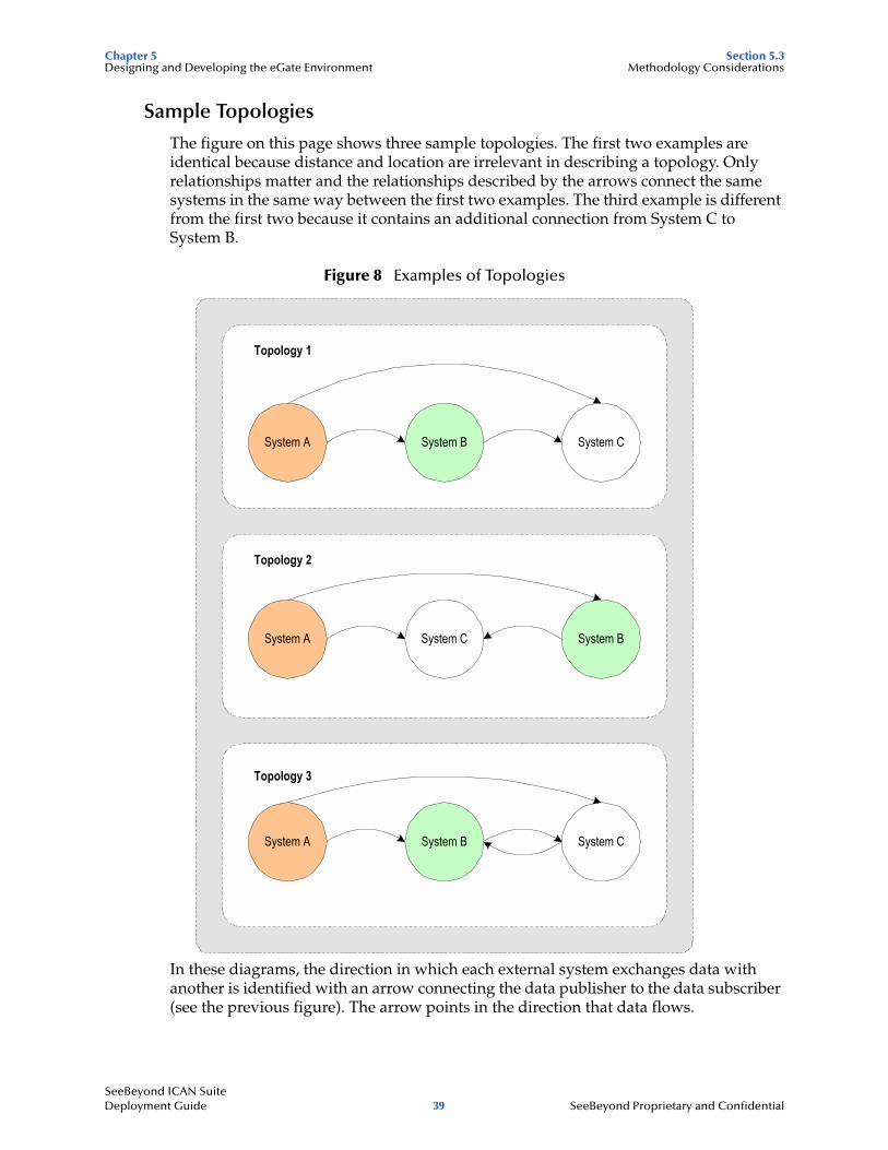
The figure on this page shows three sample topologies. The first two examples are identical because distance and location are irrelevant in describing a topology. Only relationships matter and the relationships described by the arrows connect the same systems in the same way between the first two examples. The third example is different from the first two because it contains an additional connection from System C to System B.
Figure 8 Examples of Topologies
In these diagrams, the direction in which each external system exchanges data with another is identified with an arrow connecting the data publisher to the data subscriber (see the previous figure). The arrow points in the direction that data flows.
System A System C System B
Topology 2
System A System CSystem B
Topology 1
System A System CSystem B
Topology 3
SeeBeyond ICAN Suite Deployment Guide 39 SeeBeyond Proprietary and Confidential
Chapter 5 Section 5.3Designing and Developing the eGate Environment Methodology Considerations
5.3.2 Three Basic StepsThe basic steps in designing eGate are:
! Identify all external systems to be connected.
! Define the configuration of eGate components.
! Define the configuration of hardware and network connections.
This section explains these steps in detail.
Identifying External Systems
The first step in designing eGate is to identify all the external systems to be connected to each other through the system. The resulting set of interconnected systems is called the communication topology. The communication topology exists without regard for the hardware hosts where components execute and without regard for the format of data exchanged between systems.
Configuring eGate Components
The second step is to define a configuration of eGate components, for example, eWay Intelligent Adapters, Collaborations, and Message Servers, to run on the respective hosts in the hardware topology. The component arrangement is called the component topology.
Efficiencies at this stage are gained by choosing the simplest OTDs and Collaborations. Defining the most efficient component topology depends upon the relationship of data formats. Therefore, defining object types is an integral part of designing the component topology.
Hardware and Network Connections
The third step is to define a configuration of hardware and network connections that enable the external systems to communicate as required by the communications topology. This hardware configuration is called the hardware topology.
As explained earlier, eGate is designed to run as a distributed system with central management. Only network performance and the demands on each host are relevant considerations in defining hardware topology. Because of the distributed architecture of the total system, the hardware topology is not rigidly defined. It can be adjusted as needed when system demands change. For example, increased demands on the eGate environment can be met by distributing processing across more CPUs.
For more information on how to determine and meet your hardware requirements, see Chapter 4.
SeeBeyond ICAN Suite Deployment Guide 40 SeeBeyond Proprietary and Confidential
Chapter 6
Testing, Transition to Production, and Maintenance
This chapter explains the transition-to-production phase of eGate deployment, including how to perform pre-transition testing, the transition operation, and post-transition maintenance procedures.
In this chapter
! “Introduction: Transition to Production” on page 41
! “Pre-Transition Testing” on page 43
! “Transition to Production” on page 46
! “Post-Transition Maintenance” on page 46
! “Transition to Production: Summary” on page 47
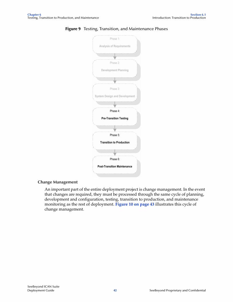
6.1 Introduction: Transition to ProductionAfter the analysis, planning, and design/development have been completed, there are three remaining deployment phases. Figure 9 on page 42 shows a diagram of the six deployment phases. This chapter explains these remaining three phases:
! Pre-transition testing: It is crucial to the success of a project to fully test the system prior to transitioning from a lab to a production environment. This testing phase includes unit testing, system testing, and performance testing. This chapter explains the possible methods of testing an eGate system in the lab.
! Transition to production: After the system is fully tested, it must be transitioned, or migrated, from the lab to its ultimate production environment. This chapter covers the procedures and considerations for performing the transition to production. Another term for this phase is the “go-live” operation.
! Post-transition maintenance: Once the system has been migrated to its production environment, it must be monitored for correct performance, the need for changes, and possible errors. System monitoring is a critical step in the long-term success of eGate. Routine checks and fine-tuning help to establish long-term performance benchmarks and aid in identifying undesirable changes.
SeeBeyond ICAN Suite Deployment Guide 41 SeeBeyond Proprietary and Confidential
Chapter 6 Section 6.1Testing, Transition to Production, and Maintenance Introduction: Transition to Production
Figure 9 Testing, Transition, and Maintenance Phases
Change Management
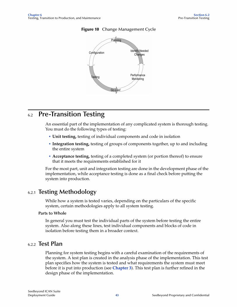
An important part of the entire deployment project is change management. In the event that changes are required, they must be processed through the same cycle of planning, development and configuration, testing, transition to production, and maintenance monitoring as the rest of deployment. Figure 10 on page 43 illustrates this cycle of change management.
Phase 1:
Analysis of Requirements
Phase 2:
Development Planning
Phase 3:
System Design and Development
Phase 4:
Pre-Transition Testing
Phase 5:
Transition to Production
Phase 6:
Post-Transition Maintenance
SeeBeyond ICAN Suite Deployment Guide 42 SeeBeyond Proprietary and Confidential
Chapter 6 Section 6.2Testing, Transition to Production, and Maintenance Pre-Transition Testing
Figure 10 Change Management Cycle
6.2 Pre-Transition TestingAn essential part of the implementation of any complicated system is thorough testing. You must do the following types of testing:
! Unit testing, testing of individual components and code in isolation
! Integration testing, testing of groups of components together, up to and including the entire system
! Acceptance testing, testing of a completed system (or portion thereof) to ensure that it meets the requirements established for it
For the most part, unit and integration testing are done in the development phase of the implementation, while acceptance testing is done as a final check before putting the system into production.
6.2.1 Testing MethodologyWhile how a system is tested varies, depending on the particulars of the specific system, certain methodologies apply to all system testing.
Parts to Whole
In general you must test the individual parts of the system before testing the entire system. Also along these lines, test individual components and blocks of code in isolation before testing them in a broader context.
6.2.2 Test PlanPlanning for system testing begins with a careful examination of the requirements of the system. A test plan is created in the analysis phase of the implementation. This test plan specifies how the system is tested and what requirements the system must meet before it is put into production (see Chapter 3). This test plan is further refined in the design phase of the implementation.
Configuration
Testing PerformanceMonitoring
Identify NeededChanges
Planning
Go-Live!
SeeBeyond ICAN Suite Deployment Guide 43 SeeBeyond Proprietary and Confidential
Chapter 6 Section 6.2Testing, Transition to Production, and Maintenance Pre-Transition Testing
The functional and technical specifications outline the exact procedure used to conduct the tests, both at a component level and at a integrated system level. These specifications include:
! Type of data to use
! Expected output
! Who is responsible for the test
Type of Data To Use
The test plan specifies the type of data to use when testing the system. It is very important both at the component level and the integration level to work with data that is typical of the data that the system is designed to process. If possible, use real data from your pre-existing systems. Vary the data enough so that all possible types of processing implemented by the system are tested.
In addition to real-life typical data, use data designed to test the system’s error handling. This data may have to be specially constructed.
Testing the Output
The test plan includes specifications for:
! Proper error handling
! Transaction processing speed
! Correct routing of information
! Correct transformation of data
! Any other special requirements
Responsibility for Testing
Who is responsible for a test depends on what type of test is done. In general, the responsibility for testing an individual component belongs to the developer who works on it. Whereas the responsibility for the testing of the entire system may fall to the project manager or the technical lead for the project. Acceptance testing is done by or in conjunction with people for whom the system is being created. Often this is the person or persons who are using the system when it is put in production.
6.2.3 Unit TestingUnit testing checks the individual parts of a larger system for correct functioning prior to integration testing.
Each component and block of code used in the system must be unit-tested and its functionality verified before it can be used in the integrated system.
Unit testing is done as part of the development phase by the developer responsible for creating the component or code block in question. If the functional or technical specifications give a procedure for testing a particular component, this procedure must
SeeBeyond ICAN Suite Deployment Guide 44 SeeBeyond Proprietary and Confidential
Chapter 6 Section 6.2Testing, Transition to Production, and Maintenance Pre-Transition Testing
be followed. If the specifications do not specify test procedures for a component, at a minimum the test must verify that the component or code block performs as outlined in the functional and technical specifications, testing individual parts of a system.
The tools used to test each part are different, depending on what the part is designed to do in the system. In addition, though all are designed to verify correct functioning, the methods employed vary, depending on the component being tested.
6.2.4 Integration TestingIntegration testing verifies how well the new components work together and with the existing eGate’s infrastructure.
If the system is large and complex, you can break the integration testing into pieces designed to test a self-contained portion of the system.
Partial Integration Testing
Partial integration testing verifies correct data movement from one external system to another, that is, a complete data path. For example, you have a system that brings in data from a single external system then sends it to several other external systems. A partial test of this system would be to test whether the data can be sent to one of the external systems.
Complete System Testing
Complete system testing tests the entire system including the interaction with all the external systems. If the system is large and complex, this type of test requires a great deal of coordination. Set up this test to duplicate the actual production system. In fact, in many cases it is used as a dry run prior to doing the actual acceptance test.
Performance Testing
Closely related to integration testing is performance testing. Integration testing tests whether the system works, performance testing tests whether the system works fast enough. This type of testing must be done once a component or system is functioning correctly and transforming the data properly. It is important that you do this type of testing in the context of integration testing, because many factors in combination affect performance. Just speeding up one component may not speed up the performance of the entire system if the bottleneck lies elsewhere.
The exact requirement or goal in terms of the system’s performance must be specified in the test plan. Whether you meet the goal determines whether you pass the test. An additional goal in performance testing is to find the bottlenecks in the system. Uncovering these bottlenecks allows additional system resources to be allocated intelligently in order to improve processing.
Speed Testing
This operation tests whether the system processes data fast enough. Make sure that the logging is set to the levels that will be used in production before doing a speed test;
SeeBeyond ICAN Suite Deployment Guide 45 SeeBeyond Proprietary and Confidential
Chapter 6 Section 6.3Testing, Transition to Production, and Maintenance Transition to Production
higher-than-normal levels of logging can seriously degrade system performance and slow processing speed.
Stress Testing
This operation tests whether the system can handle the expected load. This type of testing attempts to overload the system with data to see whether or how it could fail. Effective stress tests include large volumes of messages, large sized messages, and multiple concurrent connections. Many times, network bottlenecks can be uncovered this way. The test plan describes the methodology to employ for this type of test.
6.2.5 Acceptance TestingThis test is done before moving the system into production and is used as a final check to prove to its end-users that it performs according to plan.
Acceptance testing can be for a partial system or for a complete system. If the entire system is not being put into production at the same time, acceptance testing can be done on the portion of the system going into production.
The test plan specifies all conditions the system has to meet to be acceptable to put into production (see Table 5 on page 24). In addition, the test plan specifies the person or persons who must approve the system and must be involved in the test.
6.3 Transition to ProductionAfter fully verifying the performance and reliability of the system, the next step is to transition it to the live production environment, the transition-to-production phase, also call the go-live phase. This process can be affected by various factors, such as the proximity of the lab to the production location and the amount of equipment and information to move.
6.4 Post-Transition MaintenanceWith your eGate up and running, it is important to monitor the system’s performance, check for errors, and make any needed changes. Figure 10 on page 43 shows the overall steps to take when changes are required. Such changes must be put through the same high scrutiny as the original system design — from analysis to testing to the eventual transition to production.
6.4.1 Implementing ChangesAfter a period of time, you may have to make changes to eGate. Changes are common as the needs of your end-users evolve and as additional external systems are added.
SeeBeyond ICAN Suite Deployment Guide 46 SeeBeyond Proprietary and Confidential

Chapter 6 Section 6.5Testing, Transition to Production, and Maintenance Transition to Production: Summary
Do not make changes to the system hastily. Handle changes using the same process that was originally used to deploy your eGate. Consider the change management process illustrated in Figure 10 on page 43. Applying this same process of planning, configuration, testing, migration, monitoring, and re-evaluation ensures a sensible deployment.
See Appendix A for a sample QA report that addresses continuing system maintenance and change issues.
6.5 Transition to Production: SummaryThe proper use of a lab environment provides an excellent opportunity to verify and refine the system configuration that was implemented earlier in the deployment process. Focusing on the deployment plan ensures the smoothest possible eGate deployment.
By thoroughly unit testing and system testing the system in the lab, costly errors are avoided and the end users are much more satisfied with the final results.
Going Forward
Once all the members of your management, your Deployment Project Team, and the end-users agree that the system is up and running according to plan, you have successfully finished the deployment of your eGate.
If you have any questions about further system operation and maintenance, see the appropriate documents listed in “Supporting Documents” on page 8 or contact SeeBeyond.
SeeBeyond ICAN Suite Deployment Guide 47 SeeBeyond Proprietary and Confidential
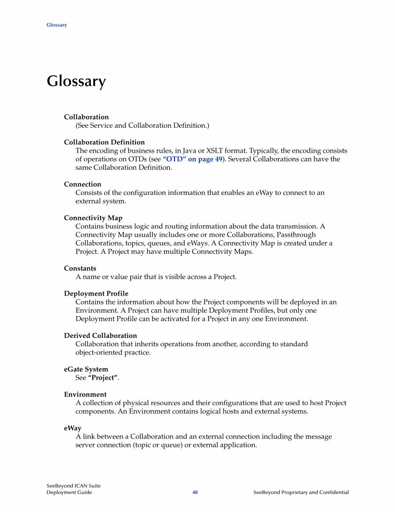
Glossary
Glossary
Collaboration(See Service and Collaboration Definition.)
Collaboration DefinitionThe encoding of business rules, in Java or XSLT format. Typically, the encoding consists of operations on OTDs (see “OTD” on page 49). Several Collaborations can have the same Collaboration Definition.
ConnectionConsists of the configuration information that enables an eWay to connect to an external system.
Connectivity MapContains business logic and routing information about the data transmission. A Connectivity Map usually includes one or more Collaborations, Passthrough Collaborations, topics, queues, and eWays. A Connectivity Map is created under a Project. A Project may have multiple Connectivity Maps.
ConstantsA name or value pair that is visible across a Project.
Deployment ProfileContains the information about how the Project components will be deployed in an Environment. A Project can have multiple Deployment Profiles, but only one Deployment Profile can be activated for a Project in any one Environment.
Derived CollaborationCollaboration that inherits operations from another, according to standard object-oriented practice.
eGate SystemSee “Project”.
EnvironmentA collection of physical resources and their configurations that are used to host Project components. An Environment contains logical hosts and external systems.
eWayA link between a Collaboration and an external connection including the message server connection (topic or queue) or external application.
SeeBeyond ICAN Suite Deployment Guide 48 SeeBeyond Proprietary and Confidential
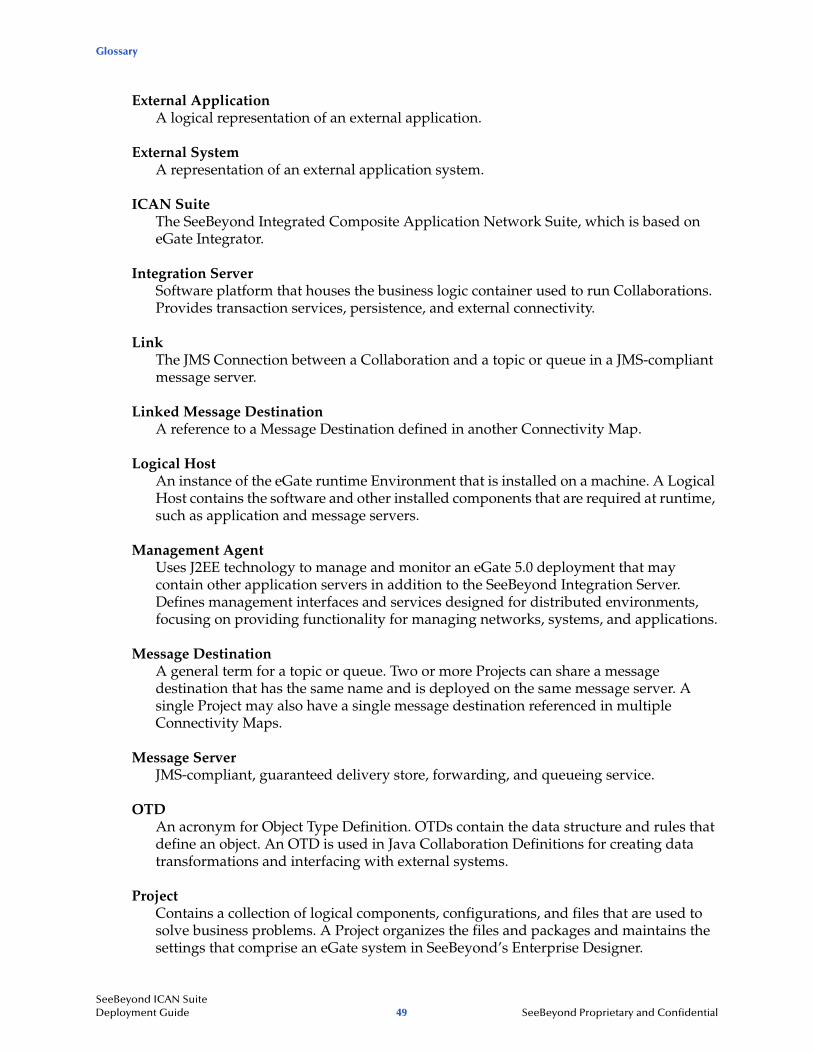
Glossary
External ApplicationA logical representation of an external application.
External SystemA representation of an external application system.
ICAN SuiteThe SeeBeyond Integrated Composite Application Network Suite, which is based on eGate Integrator.
Integration ServerSoftware platform that houses the business logic container used to run Collaborations. Provides transaction services, persistence, and external connectivity.
LinkThe JMS Connection between a Collaboration and a topic or queue in a JMS-compliant message server.
Linked Message DestinationA reference to a Message Destination defined in another Connectivity Map.
Logical HostAn instance of the eGate runtime Environment that is installed on a machine. A Logical Host contains the software and other installed components that are required at runtime, such as application and message servers.
Management AgentUses J2EE technology to manage and monitor an eGate 5.0 deployment that may contain other application servers in addition to the SeeBeyond Integration Server. Defines management interfaces and services designed for distributed environments, focusing on providing functionality for managing networks, systems, and applications.
Message DestinationA general term for a topic or queue. Two or more Projects can share a message destination that has the same name and is deployed on the same message server. A single Project may also have a single message destination referenced in multiple Connectivity Maps.
Message ServerJMS-compliant, guaranteed delivery store, forwarding, and queueing service.
OTDAn acronym for Object Type Definition. OTDs contain the data structure and rules that define an object. An OTD is used in Java Collaboration Definitions for creating data transformations and interfacing with external systems.
ProjectContains a collection of logical components, configurations, and files that are used to solve business problems. A Project organizes the files and packages and maintains the settings that comprise an eGate system in SeeBeyond’s Enterprise Designer.
SeeBeyond ICAN Suite Deployment Guide 49 SeeBeyond Proprietary and Confidential
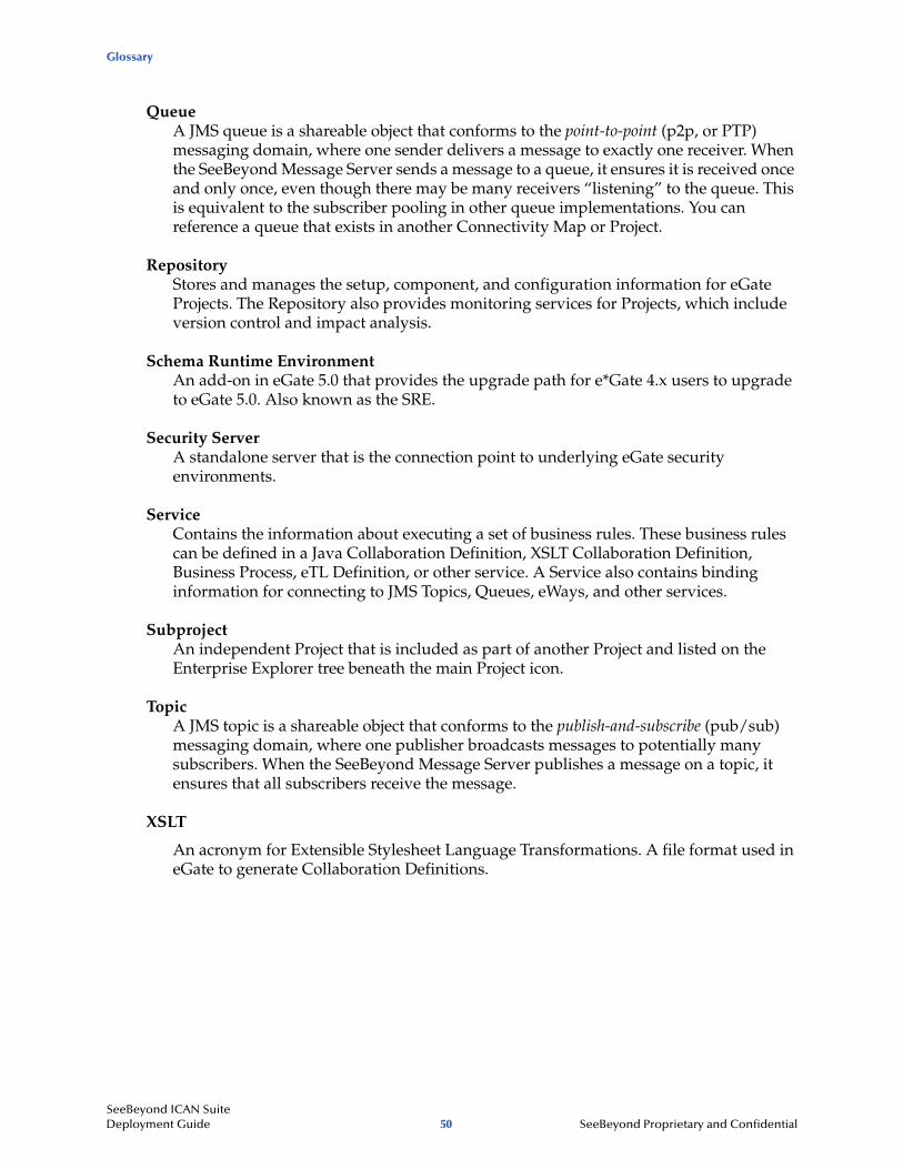
Glossary
QueueA JMS queue is a shareable object that conforms to the point-to-point (p2p, or PTP) messaging domain, where one sender delivers a message to exactly one receiver. When the SeeBeyond Message Server sends a message to a queue, it ensures it is received once and only once, even though there may be many receivers “listening” to the queue. This is equivalent to the subscriber pooling in other queue implementations. You can reference a queue that exists in another Connectivity Map or Project.
RepositoryStores and manages the setup, component, and configuration information for eGate Projects. The Repository also provides monitoring services for Projects, which include version control and impact analysis.
Schema Runtime EnvironmentAn add-on in eGate 5.0 that provides the upgrade path for e*Gate 4.x users to upgrade to eGate 5.0. Also known as the SRE.
Security ServerA standalone server that is the connection point to underlying eGate security environments.
ServiceContains the information about executing a set of business rules. These business rules can be defined in a Java Collaboration Definition, XSLT Collaboration Definition, Business Process, eTL Definition, or other service. A Service also contains binding information for connecting to JMS Topics, Queues, eWays, and other services.
SubprojectAn independent Project that is included as part of another Project and listed on the Enterprise Explorer tree beneath the main Project icon.
TopicA JMS topic is a shareable object that conforms to the publish-and-subscribe (pub/sub) messaging domain, where one publisher broadcasts messages to potentially many subscribers. When the SeeBeyond Message Server publishes a message on a topic, it ensures that all subscribers receive the message.
XSLT
An acronym for Extensible Stylesheet Language Transformations. A file format used in eGate to generate Collaboration Definitions.
SeeBeyond ICAN Suite Deployment Guide 50 SeeBeyond Proprietary and Confidential
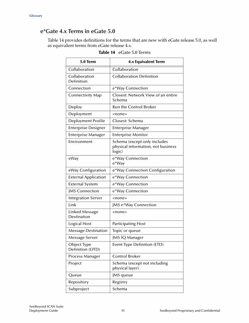
Glossary
e*Gate 4.x Terms in eGate 5.0
Table 14 provides definitions for the terms that are new with eGate release 5.0, as well as equivalent terms from eGate release 4.x.
Table 14 eGate 5.0 Terms
5.0 Term 4.x Equivalent Term
Collaboration Collaboration
Collaboration Definition
Collaboration Definition
Connection e*Way Connection
Connectivity Map Closest: Network View of an entire Schema
Deploy Run the Control Broker
Deployment <none>
Deployment Profile Closest: Schema
Enterprise Designer Enterprise Manager
Enterprise Manager Enterprise Monitor
Environment Schema (except only includes physical information, not business logic)
eWay e*Way Connectione*Way
eWay Configuration e*Way Connection Configuration
External Application e*Way Connection
External System e*Way Connection
JMS Connection e*Way Connection
Integration Server <none>
Link JMS e*Way Connection
Linked Message Destination
<none>
Logical Host Participating Host
Message Destination Topic or queue
Message Server JMS IQ Manager
Object Type Definition (OTD)
Event Type Definition (ETD)
Process Manager Control Broker
Project Schema (except not including physical layer)
Queue JMS queue
Repository Registry
Subproject Schema
SeeBeyond ICAN Suite Deployment Guide 51 SeeBeyond Proprietary and Confidential

Glossary
Topic JMS topic
XSLT <none>
Table 14 eGate 5.0 Terms (Continued)
5.0 Term 4.x Equivalent Term
SeeBeyond ICAN Suite Deployment Guide 52 SeeBeyond Proprietary and Confidential
Index
Index
Aacceptance testing 46AIX
CPU requirements 32disk space requirements 32RAM requirements 32
analysis and planning overview 12analysis of needs cycle 18analysis of requirements categories 15Analysis of Requirements Phase definition 12Approved Proposal 19, 20architecture 10
Cchange management 20, 24, 42Collaboration 48, 51
derived 48Collaboration definition 48, 51components
eWay 40connection 48, 51Connectivity Map 48, 51constants 48Control Broker 51conventions
path name separator 8Windows 8
CPUestimating requirements 28
CPU requirementsAIX 32HP Tru64 32HP-UX 32Red Hat Linux 32Solaris 31Windows 31
Ddeploy 51Deployment 51deployment
estimating CPU requirements 28
gathering information 13overview of phases 13planning steps 19
Deployment Checklist 20, 24Deployment Planning Phase definition 12Deployment Profile 48, 51Deployment Project Plan 21, 25, 26Deployment Project Team 17, 20, 21, 24, 25derived Collaboration 48Design and Development Team 19, 24disk space requirements
AIX 32HP Tru64 32HP-UX 32Red Hat Linux 32Solaris 31Windows 31
distributed systems introduction 35document
conventions 7
Ee*Way 51e*Way Connection 51e*Way Connection Configuration 51eGate system 48Enterprise Designer 51Enterprise Manager 51Enterprise Monitor 51Environment 48, 51ETD 51Event Type Definition 51eWay 48, 51eWay Configuration 51external
application 49, 51system 49, 51
FFunctional Requirements Specification 22, 23, 25
Ggathering deployment information
introduction 13research and interviews 14surveys 14
Hhardware
SeeBeyond ICAN Suite Deployment Guide 53 SeeBeyond Proprietary and Confidential
Index
determining requirements 27initial considerations 28minimum requirements 28
HP Tru64CPU requirements 32disk space requirements 32RAM requirements 32
HP-UXCPU requirements 32disk space requirements 32RAM requirements 32
IICAN Suite 49installation, software and hardware 20Integration Server 49, 51integration testing 45
JJMS
connection 51e*Way Connection 51IQ Manager 51queue 51topic 52
Llink 49, 51linked message destination 49, 51Logical Host 49, 51
MManagement Agent 49message
destination 49, 51server 49, 51
methodology, deploymentbasic steps 40configuring components 40hardware and network connections 40identifying external systems 40introduction 38sample topologies 39topology definition 38
elements 38migration. See transition to production
Nnetwork view 51
OObject Type Definition 49, 51OTD 49, 51
PParticipating Host 51performance testing 45planning deployment
determining when objectives are met 24identifying and scheduling tasks 20
deployment documents 21deployment initiation 20
overview of steps 19, 25setting up overall objectives 19
Process Manager 51product architecture 10Professional Services Department, SeeBeyond 14, 19Project 49, 51project manager 20, 21
Qqueue 50, 51
RRAM requirements
AIX 32HP Tru64 32HP-UX 32Red Hat Linux 32Solaris 31Windows 31
Red Hat LinuxCPU requirements 32disk space requirements 32RAM requirements 32
Registry 51Repository 50, 51requirements, analyzing for deployment
business planning needs 17introduction 14operation and performance needs 16personnel and training needs 17system-specific needs 15
SeeBeyond ICAN Suite Deployment Guide 54 SeeBeyond Proprietary and Confidential
Index
Sscaling, examples 37Schema 51Schema Runtime Environment 50Security Server 50software systems, common view 35Solaris
CPU requirements 31disk space requirements 31RAM requirements 31
speed testing 45SRE 50stress testing 46subproject 50, 51supporting documents 8system basic architecture 37system design
introduction 33methodology 34
system developmentmethodology 35
system model/diagram 23system testing 45
TTechnical Requirements Specification 23, 25test plan 43Test Plan Requirements Specification 23, 25testing 43–46
acceptance testing 46integration testing 45performance testing 45speed testing 45stress testing 46system testing 45test plan 43unit testing 44
Testing Team 24topic 50, 51, 52transition to production 46
Uunit testing 44
WWindows
CPU requirements 31disk space requirements 31RAM requirements 31
writing conventions 7
XXSLT 50, 52
SeeBeyond ICAN Suite Deployment Guide 55 SeeBeyond Proprietary and Confidential