sun seebeyond egate(tm) integrator tutorial - oracle documentation
TRANSCRIPT
SUN SEEBEYOND
eGATE™ INTEGRATOR TUTORIAL
Release 5.1.2

eGate Integrator Tutorial 2 Sun Microsystems, Inc.
Copyright © 2006 Sun Microsystems, Inc., 4150 Network Circle, Santa Clara, California 95054, U.S.A. All rights reserved. Sun Microsystems, Inc. has intellectual property rights relating to technology embodied in the product that is described in this document. In particular, and without limitation, these intellectual property rights may include one or more of the U.S. patents listed at http://www.sun.com/patents and one or more additional patents or pending patent applications in the U.S. and in other countries. U.S. Government Rights - Commercial software. Government users are subject to the Sun Microsystems, Inc. standard license agreement and applicable provisions of the FAR and its supplements. Use is subject to license terms. This distribution may include materials developed by third parties. Sun, Sun Microsystems, the Sun logo, Java, Sun Java Composite Application Platform Suite, SeeBeyond, eGate, eInsight, eVision, eTL, eXchange, eView, eIndex, eBAM, eWay, and JMS are trademarks or registered trademarks of Sun Microsystems, Inc. in the U.S. and other countries. All SPARC trademarks are used under license and are trademarks or registered trademarks of SPARC International, Inc. in the U.S. and other countries. Products bearing SPARC trademarks are based upon architecture developed by Sun Microsystems, Inc. UNIX is a registered trademark in the U.S. and other countries, exclusively licensed through X/Open Company, Ltd. This product is covered and controlled by U.S. Export Control laws and may be subject to the export or import laws in other countries. Nuclear, missile, chemical biological weapons or nuclear maritime end uses or end users, whether direct or indirect, are strictly prohibited. Export or reexport to countries subject to U.S. embargo or to entities identified on U.S. export exclusion lists, including, but not limited to, the denied persons and specially designated nationals lists is strictly prohibited.
Copyright © 2006 Sun Microsystems, Inc., 4150 Network Circle, Santa Clara, California 95054, Etats-Unis. Tous droits réservés. Sun Microsystems, Inc. détient les droits de propriété intellectuels relatifs à la technologie incorporée dans le produit qui est décrit dans ce document. En particulier, et ce sans limitation, ces droits de propriété intellectuels peuvent inclure un ou plus des brevets américains listés à l'adresse http://www.sun.com/patents et un ou les brevets supplémentaires ou les applications de brevet en attente aux Etats - Unis et dans les autres pays. L'utilisation est soumise aux termes de la Licence. Cette distribution peut comprendre des composants développés par des tierces parties. Sun, Sun Microsystems, le logo Sun, Java, Sun Java Composite Application Platform Suite, Sun, SeeBeyond, eGate, eInsight, eVision, eTL, eXchange, eView, eIndex, eBAM et eWay sont des marques de fabrique ou des marques déposées de Sun Microsystems, Inc. aux Etats-Unis et dans d'autres pays. Toutes les marques SPARC sont utilisées sous licence et sont des marques de fabrique ou des marques déposées de SPARC International, Inc. aux Etats-Unis et dans d'autres pays. Les produits portant les marques SPARC sont basés sur une architecture développée par Sun Microsystems, Inc. UNIX est une marque déposée aux Etats-Unis et dans d'autres pays et licenciée exclusivement par X/Open Company, Ltd. Ce produit est couvert à la législation américaine en matière de contrôle des exportations et peut être soumis à la règlementation en vigueur dans d'autres pays dans le domaine des exportations et importations. Les utilisations, ou utilisateurs finaux, pour des armes nucléaires, des missiles, des armes biologiques et chimiques ou du nucléaire maritime, directement ou indirectement, sont strictement interdites. Les exportations ou réexportations vers les pays sous embargo américain, ou vers des entités figurant sur les listes d'exclusion d'exportation américaines, y compris, mais de manière non exhaustive, la liste de personnes qui font objet d'un ordre de ne pas participer, d'une façon directe ou indirecte, aux exportations des produits ou des services qui sont régis par la législation américaine en matière de contrôle des exportations et la liste de ressortissants spécifiquement désignés, sont rigoureusement interdites.
Part Number: 819-7467-10
Version 20061006130136
Contents
eGate Integrator Tutorial 3 Sun Microsystems, Inc.
Contents
List of Figures 8
Chapter 1
Introduction 14About this Document 14
What’s in this Document 14Scope 15Intended Audience 15Text Conventions 15Screenshots Used in this Document 16
Related Documents 16
Suite Installation Requirements 16
Sun Microsystems, Inc. Web Site 17
Documentation Feedback 17
Chapter 2
Features of the Enterprise Designer 18Enterprise Designer Objects and Components 18
Menu Bar 19
Enterprise Explorer 20
Project Editor 20
Chapter 3
Building a Project - Scenario1 21Files Required for the Tutorials 22
Sample Files Used in the Tutorial 22
Sample Data 22Download the Sample files 23Sample Input XML File 25Input (DTD) 25Output (XSD) 26
Contents
eGate Integrator Tutorial 4 Sun Microsystems, Inc.
Actual output file 26
Business Challenge 26
Project Description 27Project Flow Diagram - Scenario1 28
Start Repository Server and Enterprise Designer 28
Create a New Project 29
Create a New Object Type Definition 31
Configure the Services 36Configure Service1 36
Apply Business Rules 43Multiplication Logic 46
Create a Connectivity Map 50Populate the Connectivity Map 52
Apply the Collaboration 53Link Objects in the Connectivity Map 54
Configure the eWays 56Multiple records per File (True or False) 58
Create an Environment 58
Create the Deployment Profile 62
Build and Deploy the Project 64Create a Domain 64Enter Passwords and Set URLs 65Build 67Deploy 68
Verify the Output Data 68Text Editor 70
Chapter 4
Building a Project - Scenario2 71Business Challenge 71
Project Overview 72Project Description 72Naming Conventions used in this Scenario 73Project Flow Diagram - Scenario2 74
Sample Data for Project2 74Download the Sample File 75
Sample Input Text Data/File 75Sample Output Text Data/File 75
Create a New Project 75
Create a New Object Type Definition 78
Contents
eGate Integrator Tutorial 5 Sun Microsystems, Inc.
Create a User-Defined OTD for the Input File 78Test Input Data 82Create a User-Defined OTD for the Output File 84
Configure a Service for Input 86Configure svc_Timecard_in 86
Apply Business Rules 91
Configure a Service for Output 93
Apply Business Rules for jcd_Payroll_out 99
Create a Connectivity Map 104
Add Objects to the Connectivity Map 106Populate the Connectivity Map 106Link Components in the Connectivity Map 108
Configure eWays and JMS Connections 111JMS Client Configuration 114
Create an Environment 115Set Properties for Servers and External Files 117
Create and Activate the Deployment Profile 120
Build and Deploy the Project 122Domain Manager 122Build 122Deploy 123
Verify Output Data 123
Chapter 5
Building a Project - Scenario3 125Using XSD Objects to Generate XSD Nodes 125
Business Challenge 125Project Description 126Project Flow Diagram - Scenario3 127
Sample Data for Project3 127Download the Sample files 128Sample files 128Input XML File 128Input XML Schema 128Output XML Schema (XSD) 129
Create a New Project 129
Import a Schema Definition 131
Export Schema Definitions to XSD Nodes 138Create a Java Collaboration 140
Apply Business Rules 146Concatenation Logic 146
Contents
eGate Integrator Tutorial 6 Sun Microsystems, Inc.
Multiplication Logic 149
Create a Connectivity Map 153Populate the Connectivity Map 154Link Components in the Connectivity Map 156
Configure the eWays 158
Create an Environment 160
Create Deployment Profile 163
Build and Deploy the Project 165Enter Passwords 165
Set the Properties for the File eWays 167Build 168Deploy 168
Verify Output Data 169Edit Input File in Real Time 170
Chapter 6
Web Services - Scenario4 172Expose a JCD as a Web Service 172
Required Resources 173Download the Sample File 175
Sample Input Schema 175Sample Output Schema 175Sample Input File 175
Create a New Project 175
Create an Object Type Definition 178
Create a Java Collaboration Definition 181
Map Business Rules 186
Create a Connectivity Map 190Apply the Collaboration 190
Create an Environment 194Add logical Host and Services 194
Create and Activate a Deployment Profile 198
Sample Input and Output Data 201
Chapter 7
Enterprise Manager Overview 203Install and Run the Enterprise Manager 203
Install the eWay Monitor and File eWay Monitor 205

Contents
eGate Integrator Tutorial 7 Sun Microsystems, Inc.
Monitor your Project 208
Glossary 210e*Gate 4.x Terms in eGate 5.0 213
Index 215
List of Figures
eGate Integrator Tutorial 8 Sun Microsystems, Inc.
List of Figures
Figure 1 Enterprise Designer 19
Figure 2 Enterprise Manager Login 23
Figure 3 Documentation Tab 24
Figure 4 Download the Sample zip File 24
Figure 5 Project Connectivity Map 27
Figure 6 Project Flowchart - Scenario1 28
Figure 7 Enterprise Designer Login 29
Figure 8 Create a Project 30
Figure 9 Project Folder: Project1 30
Figure 10 OTD Wizard (DTD) 31
Figure 11 Select DTD File 32
Figure 12 Select Document Elements 33
Figure 13 Select OTD Options 33
Figure 14 OTD Wizard (XSD) 34
Figure 15 Select Output Elements 35
Figure 16 Select OTD Options 35
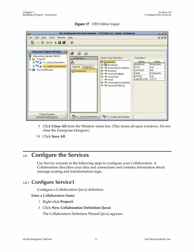
Figure 17 OTD Editor Input 36
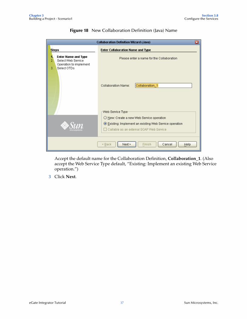
Figure 18 New Collaboration Definition (Java) Name 37
Figure 19 Select Web Service File Receive 38
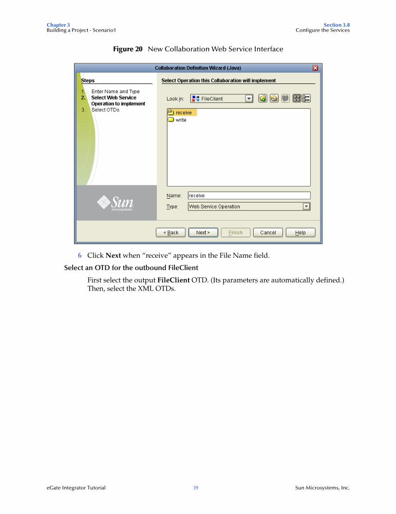
Figure 20 New Collaboration Web Service Interface 39
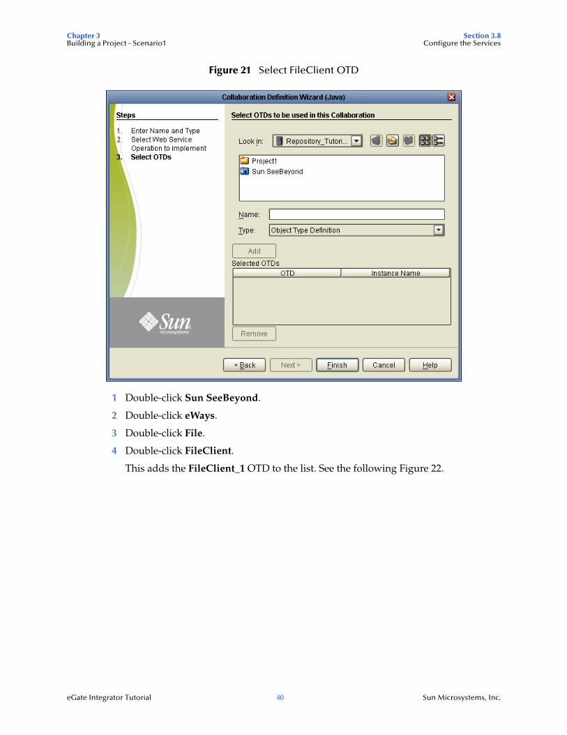
Figure 21 Select FileClient OTD 40
Figure 22 Select Employee OTDs 41
Figure 23 Selected OTDs 42
Figure 24 Collaboration Editor (Java) 43
Figure 25 Unmarshal Text 44
Figure 26 Business Designer - Unmarshal Text 44
Figure 27 Employee Number Node 45
Figure 28 Concatenation Logic 46
Figure 29 Multiplication Logic 47
Figure 30 Collapse For Loop 47
Figure 31 Source Code Mode 48
Figure 32 Marshal to String 49
Section List of Figures
eGate Integrator Tutorial 9 Sun Microsystems, Inc.
Figure 33 View Business Rules 49
Figure 34 Write Output File 50
Figure 35 Create a Connectivity Map 51
Figure 36 Project1 with a Connectivity Map (CMap1) 52
Figure 37 External Application Selection 53
Figure 38 Objects in Connectivity Map 54
Figure 39 Using the Drag and Drop method 54
Figure 40 Connect FileClient to File1 55
Figure 41 Connect FileClient to File2 55
Figure 42 Inbound eWay 56
Figure 43 Properties Configuration (Inbound eWay) 56
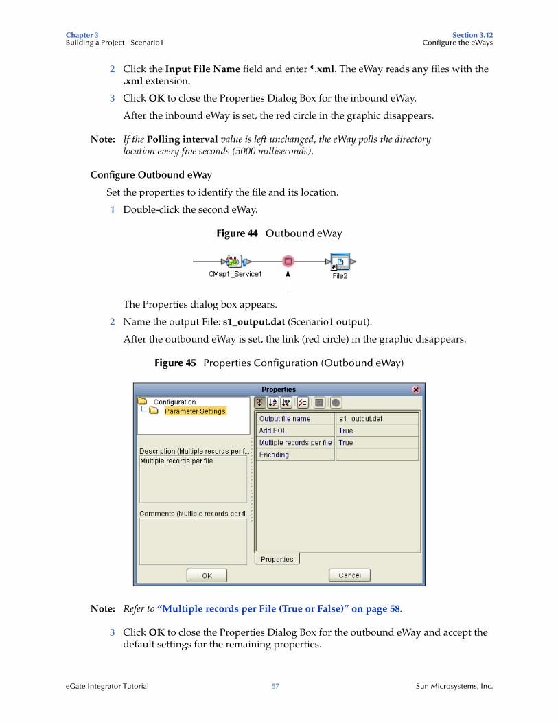
Figure 44 Outbound eWay 57
Figure 45 Properties Configuration (Outbound eWay) 57
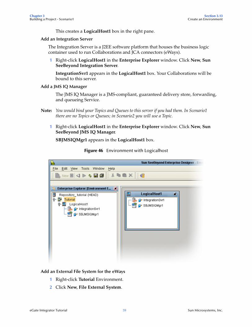
Figure 46 Environment with Logicalhost 59
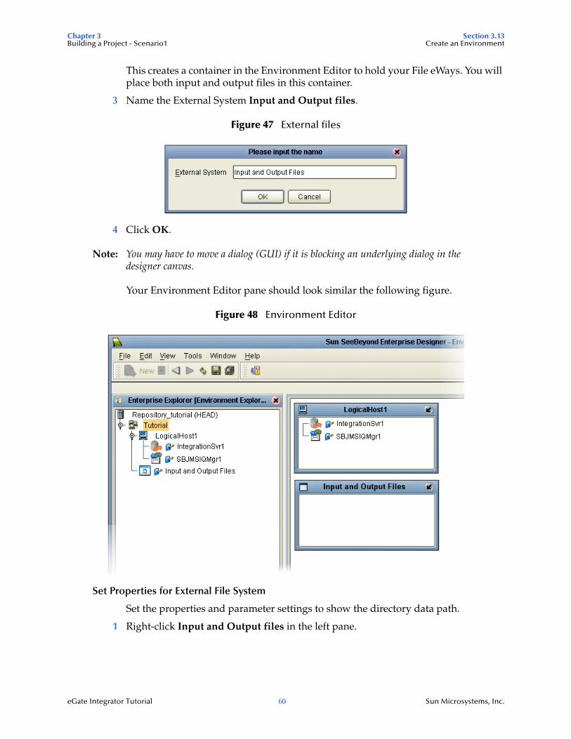
Figure 47 External files 60
Figure 48 Environment Editor 60
Figure 49 Properties Pop-up Box 61
Figure 50 Properties, Parameter Settings 61
Figure 51 Deployment Profile 62
Figure 52 Environment, Deployment Editor 63
Figure 53 Populated Environment 64
Figure 54 Start Domain Manager 65
Figure 55 Integration Server Password 66
Figure 56 IQ Manager 67
Figure 57 Build Button 67
Figure 58 Project Build Successful 67
Figure 59 Deployment Successful 68
Figure 60 Output File 69
Figure 61 Input File 69
Figure 62 The Relationship Between the Two Systems 72
Figure 63 Project Connectivity Map 73
Figure 64 Project Flowchart - Scenario2 74
Figure 65 Enterprise Designer Login Dialog Box 76
Figure 66 Create a Project 77
Figure 67 Project Folder: prj_2_UD 77
Figure 68 OTD Wizard Selection 78
Figure 69 OTD Editor for Input 79
Figure 70 Delimiter Settings 80
Section List of Figures
eGate Integrator Tutorial 10 Sun Microsystems, Inc.
Figure 71 User-Defined Input OTD Editor 81
Figure 72 Set Field Names and Delimiters 82
Figure 73 Test Input Data 83
Figure 74 Marshal to String 84
Figure 75 Delimiter Settings 85
Figure 76 User-Defined Output OTD Editor 86
Figure 77 New Collaboration Definition (Java) Name 87
Figure 78 New Collaboration Definition Wizard (Java) 88
Figure 79 New Collaboration Web Service Interface 89
Figure 80 New Collaboration Select OTD 90
Figure 81 Business Rules Designer 91
Figure 82 Methods Dialog Box 92
Figure 83 Send Text Payload 93
Figure 84 New Collaboration Definition Editor (Java) 94
Figure 85 Receive from Topic 95
Figure 86 Select OTDs for jcd_Payroll_out 96
Figure 87 Input/Output OTDs 97
Figure 88 Drop Down Arrow button 98
Figure 89 File Client OTD 99
Figure 90 Business Rules Designer for jcd_Payroll_out 100
Figure 91 Unmarshal From String 101
Figure 92 Multiplication - Logical 102
Figure 93 Multiplication - Actual 102
Figure 94 Close Loop 103
Figure 95 Marshal Text 103
Figure 96 Write File Application 104
Figure 97 Create a Connectivity Map 105
Figure 98 Connectivity Map Icon 105
Figure 99 prj_2_UD with a Connectivity Map (cm_2_UD) 106
Figure 100 External Application Selection 107
Figure 101 Unlinked Objects in Connectivity Map 109
Figure 102 Using the Drag-and-Drop Method 109
Figure 103 Unlinked Connectivity Map 110
Figure 104 CMap Generator Options 110
Figure 105 Select CMap Generator Components 111
Figure 106 Connected CMap Components 111
Figure 107 Inbound eWay 112
Figure 108 Properties Configuration (Inbound eWay) 112
Section List of Figures
eGate Integrator Tutorial 11 Sun Microsystems, Inc.
Figure 109 Outbound eWay 113
Figure 110 Properties Configuration (Outbound eWay) 113
Figure 111 JMS Client Properties Icon 114
Figure 112 JMS Client Properties 114
Figure 113 Environment with Logicalhost 116
Figure 114 Environment Editor 117
Figure 115 Properties, Parameter Settings 118
Figure 116 Integration Server Password 119
Figure 117 Message Server 119
Figure 118 Deployment Profile 120
Figure 119 Environment, Drag and Drop Components 121
Figure 120 Automap Results 121
Figure 121 Environment Toolbar Buttons 122
Figure 122 Output File 123
Figure 123 Input File 124
Figure 124 Project Connectivity Map 126
Figure 125 Project Flowchart - Scenario3 127
Figure 126 Enterprise Designer Login 130
Figure 127 Create a Project 131
Figure 128 Project3 131
Figure 129 Select Schema Definition 132
Figure 130 Import From File Location 133
Figure 131 XML Schemas (XSDs) 134
Figure 132 Import Preview 135
Figure 133 Project Explorer Preview 136
Figure 134 Import All 136
Figure 135 Imported Successfully 137
Figure 136 Verify XML Definition 138
Figure 137 Export to OTD 139
Figure 138 Exported OTD 140
Figure 139 Collaboration Definition (Java) Name 141
Figure 140 Collaboration Definition Wizard (Java) 141
Figure 141 New Collaboration Web Service Interface 142
Figure 142 Select OTDs 143
Figure 143 Select FileClient OTD 144
Figure 144 Selected OTDs 145
Figure 145 Collaboration Editor (Java) 146
Figure 146 Unmarshal Text 147
Section List of Figures
eGate Integrator Tutorial 12 Sun Microsystems, Inc.
Figure 147 Business Designer - Unmarshal Text 148
Figure 148 Concatenation Logic 149
Figure 149 Mapped Multiplication Operation 150
Figure 150 Collapse For Loop 150
Figure 151 Marshal to String 151
Figure 152 Marshal Text 152
Figure 153 Write Output File 153
Figure 154 Connectivity Map Active 154
Figure 155 External Application Selection 155
Figure 156 Connectivity Map 156
Figure 157 Automap Components 157
Figure 158 Connectivity Map Generator 158
Figure 159 Inbound File eWay 158
Figure 160 Properties Configuration (Inbound File eWay) 159
Figure 161 Outbound File eWay 159
Figure 162 Properties Configuration (Outbound File eWay) 160
Figure 163 Environment with Logicalhost 162
Figure 164 External files 162
Figure 165 Environment Editor 163
Figure 166 Deployment Profile 164
Figure 167 Environment Automap Components 164
Figure 168 Integration Server Password 166
Figure 169 JMS IQ Manager 167
Figure 170 Properties Setting for the Inbound File eWay 168
Figure 171 Build Button 168
Figure 172 Deploy Button 169
Figure 173 Deployment Successful 169
Figure 174 Output File 170
Figure 175 Input File 170
Figure 176 Download 173
Figure 177 Select UDDI Server 174
Figure 178 Enterprise Designer Login Dialog Box 176
Figure 179 Create a WS Project 177
Figure 180 Project Folder: prj_Web_Ser 177
Figure 181 Select XSD Wizard 178
Figure 182 Navigate to XSD Schemas 179
Figure 183 Select OTD Options 180
Figure 184 Employee OTD 181
Section List of Figures
eGate Integrator Tutorial 13 Sun Microsystems, Inc.
Figure 185 Java Collaboration 182
Figure 186 Collaboration Name 183
Figure 187 Operation Name 183
Figure 188 Select Message Input 184
Figure 189 Select Additional OTDs 185
Figure 190 Collaboration Editor 186
Figure 191 Map Employee Number 187
Figure 192 Concat Method 188
Figure 193 Number to String Conversion 189
Figure 194 Mapped Multiplication Rule 189
Figure 195 Connectivity Map 191
Figure 196 Partner Port type 192
Figure 197 WSDL Binding Editor 193
Figure 198 Map Connection 193
Figure 199 Map Completed 194
Figure 200 SOAP External System 195
Figure 201 UDDI_Ext Properties 196
Figure 202 Web Service Environment 197
Figure 203 IS Properties 198
Figure 204 Deployment Profile 199
Figure 205 Deployed Components 200
Figure 206 Build Message 200
Figure 207 Build Successful 201
Figure 208 Deploy Successful 201
Figure 209 Enterprise Manager Security Gateway 204
Figure 210 Enterprise Manager Monitor and Runtime Administration 204
Figure 211 Add Runtime Server 205
Figure 212 Web Applications Manager 206
Figure 213 Auto-install eWay Monitors 206
Figure 214 Applications Available for Installation 207
Figure 215 View Results of Install 207
Figure 216 Monitor Service 208
Figure 217 JMS IQ Manager 208
Figure 218 Connectivity Map 209
Figure 219 Deployed Applications 209
eGate Integrator Tutorial 14 Sun Microsystems, Inc.
Chapter 1
Introduction
Welcome to the Sun SeeBeyond eGate™ Integrator Tutorial. The Tutorial must be run on a Windows platform. The Repository and Logical Host may be installed on any supported platform, but the Enterprise Designer must be installed and run on a Windows computer.
This document contains sample scenarios to help you get started with eGate Integrator. These sample scenarios are very basic and are intended for new eGate users. Sample files are provided along with the documentation. These scenarios are “end-to-end” Projects. In doing these sample scenarios, you will create, deploy, and run Projects to produce output which can be verified.
What’s in This Chapter
“About this Document” on page 14
“Related Documents” on page 16
“Suite Installation Requirements” on page 16
“Sun Microsystems, Inc. Web Site” on page 17
“Documentation Feedback” on page 17
1.1 About this DocumentThis document contains the procedures to complete sample scenarios that demonstrate some of the basics of the eGate Integrator product. You can use the sample data provided to go through these scenarios and quickly learn the basics.
1.1.1 What’s in this DocumentChapter 1 “Introduction” overviews the contents of the Sun SeeBeyond eGate Integrator Tutorial, describes the writing conventions used in this document, and provides a complete list of related eGate Integrator documentation.
Chapter 2 “Features of the Enterprise Designer” introduces the Enterprise Designer, Menu Bar, Enterprise Explorer, and Project Editor.
Chapter 3 “Building a Project - Scenario1” provides a step-by-step, end-to-end scenario where you perform a data concatenation. Scenario1 uses an input DTD (OTD) to create an output XSD (OTD).
Chapter 1 Section 1.1Introduction About this Document
eGate Integrator Tutorial 15 Sun Microsystems, Inc.
Chapter 4 “Building a Project - Scenario2” provides a step-by-step, end-to-end scenario where you perform data transformation, involving a multiplication operation. Scenario2 uses a user-defined OTD.
Chapter 5 “Building a Project - Scenario3” provides a step-by-step, end-to-end scenario involving a concatenation and a multiplication operation where you create an eGate Project using XSD schemas to create OTDs.
Chapter 6 “Web Services - Scenario4” provides a step-by-step, end-to-end scenario that exposes a (JCD) Java Collaboration Definition as a Web service.
Chapter 7 “Enterprise Manager Overview” provides an overview of the Enterprise Manager which is used to view and monitor projects dynamically.
“Glossary”.
“Index”
1.1.2 ScopeThis eGate Integrator Tutorial provides four scenarios to lead you through all the steps required to successfully build and run an end-to-end Project, including bringing data in using OTDs, manipulating data using Collaborations, deploying the Project, and viewing the results. Sample data and the expected output are provided for each scenario.
1.1.3 Intended AudienceThis document is intended for eGate Integrator users who want to create and deploy a sample Project, end-to-end, using the sample data provided by Sun Microsystems. This document also serves as a hands-on introduction to eGate Integrator to help new users get up to speed quickly.
1.1.4 Text ConventionsThe following conventions are observed throughout this document.
Table 1 Text Conventions
Text Convention Used For Examples
Bold Names of buttons, files, icons, parameters, variables, methods, menus, and objects
Click OK.On the File menu, click Exit.Select the eGate.sar file.
Monospaced Command line arguments, code samples; variables are shown in bold italic
java -jar filename.jar
Blue bold Hypertext links within document
See Text Conventions on page 15
Chapter 1 Section 1.2Introduction Related Documents
eGate Integrator Tutorial 16 Sun Microsystems, Inc.
1.1.5 Screenshots Used in this DocumentDepending on what products you have installed, and how they are configured, the screenshots in this document may differ from what you see on your system.
1.2 Related DocumentsThe following Sun Microsystems documents provide additional information about eGate Integrator and the Composite Application Platform Suite:
Composite Application Platform Suite Installation Guide
eGate Integrator System Administration Guide
eGate Integrator Release Notes
eGate Integrator User’s Guide
Composite Application Platform Suite Primer
1.3 Suite Installation RequirementsTo simplify these examples, this tutorial assumes you have all of the following eGate objects and components installed on a single Windows system:
eGate Repository
Logical Host
Enterprise Designer
eGate Integrator product
File eWay product
Refer to the Installation Guide for system requirements and installation instructions. See also: Chapter 3, Files Required for the Tutorials on page 22.
Blue underlined Hypertext links for Web addresses (URLs) or email addresses
http://www.sun.com
Table 1 Text Conventions (Continued)
Text Convention Used For Examples
Chapter 1 Section 1.4Introduction Sun Microsystems, Inc. Web Site
eGate Integrator Tutorial 17 Sun Microsystems, Inc.
1.4 Sun Microsystems, Inc. Web SiteThe Sun Microsystems web site is your best source for up-to-the-minute product news and technical support information. The site’s URL is:
http://www.sun.com
1.5 Documentation FeedbackWe appreciate your feedback. Please send any comments or suggestions regarding this document to:
eGate Integrator Tutorial 18 Sun Microsystems, Inc.
Chapter 2
Features of the Enterprise Designer
The Enterprise Designer is the graphical user interface (GUI) used to design and implement Sun Java Composite Application Platform Suite (Java CAPS) projects. This chapter overviews the features and interface of the Enterprise Designer window.
What’s in This Chapter
Enterprise Designer Objects and Components on page 18
Menu Bar on page 19
Enterprise Explorer on page 20
Project Editor on page 20
2.1 Enterprise Designer Objects and ComponentsThe Enterprise Designer is used to create and configure the components of an eGate Project. Each object of this interface is identified in Figure 1.
An object is a more generic term and also refers to eWays. A component usually describes a runnable “thing,” such as a Java Collaboration.
Chapter 2 Section 2.2Features of the Enterprise Designer Menu Bar
eGate Integrator Tutorial 19 Sun Microsystems, Inc.
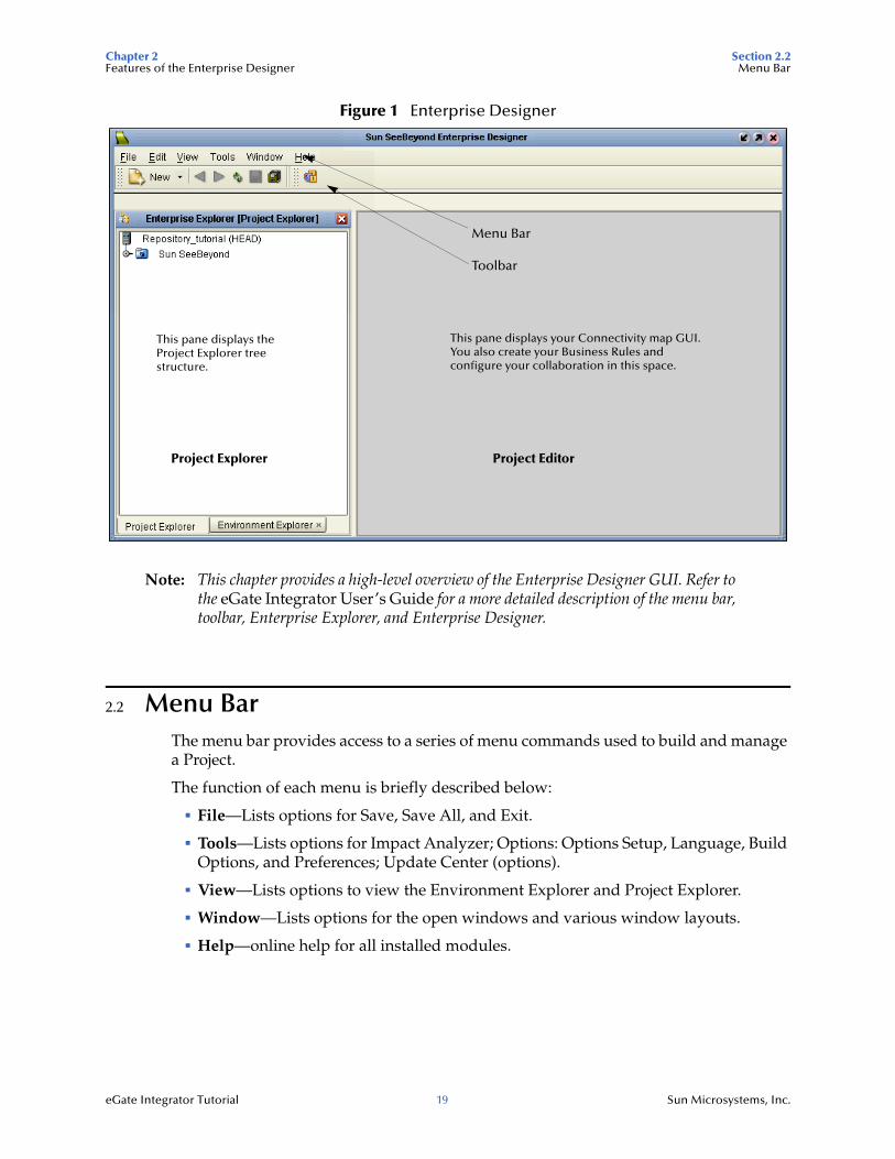
Figure 1 Enterprise Designer
Note: This chapter provides a high-level overview of the Enterprise Designer GUI. Refer to the eGate Integrator User’s Guide for a more detailed description of the menu bar, toolbar, Enterprise Explorer, and Enterprise Designer.
2.2 Menu BarThe menu bar provides access to a series of menu commands used to build and manage a Project.
The function of each menu is briefly described below:
File—Lists options for Save, Save All, and Exit.
Tools—Lists options for Impact Analyzer; Options: Options Setup, Language, Build Options, and Preferences; Update Center (options).
View—Lists options to view the Environment Explorer and Project Explorer.
Window—Lists options for the open windows and various window layouts.
Help—online help for all installed modules.
Project Explorer
Menu Bar
Toolbar
Project Editor
This pane displays theProject Explorer treestructure.
This pane displays your Connectivity map GUI.You also create your Business Rules andconfigure your collaboration in this space.
Chapter 2 Section 2.3Features of the Enterprise Designer Enterprise Explorer
eGate Integrator Tutorial 20 Sun Microsystems, Inc.
2.3 Enterprise ExplorerThe Enterprise Explorer organizes all of the objects and components of a Project into a series of folders and contains the following two tabs:
Project Explorer—Logical configurations designed to help solve a business problem. This branch includes all the objects and components of an Enterprise Designer Project, including Connectivity Maps, Services, Object Type Definitions (OTD), and Deployment Profiles.
Environment Explorer—Collections of logical hosts and external systems capable of hosting eGate objects and components and information about external systems, which may be involved with an eGate configuration. You will go into the Environment Explorer when you are ready to deploy and run your project.
2.4 Project EditorThe Project Editor is where you use GUI tools (or even enter code directly) to create a Project. This part of the Enterprise Designer is empty when you start a new Project. However, as you work through the tutorial, the Project Editor quickly fills with objects and graphical structures representing the various stages of the Project. The types of windows in the Project Editor area include:
Connectivity Map—Contains business logic objects and components, such as Services, Topics, Queues, and eWays, that you include in the design of a Project.
Collaboration Editor (Java)—Contains the business rules defined in Java.
Collaboration Editor (XSLT)—Contains the business rules defined in XSLT.
OTD Editor—Edits and tests the OTDs (Object Type Definitions).
Deployment Profile Editor—Edits the deployment profile. A Deployment Profile contains information about how Project components are mapped and deployed within an Environment.
Environment—Collection of physical resources (logical hosts and external systems).
eGate Integrator Tutorial 21 Sun Microsystems, Inc.
Chapter 3
Building a Project - Scenario1
This Tutorial provides step-by-step procedures for creating an eGate Project. This Project addresses a very simple business challenge where an input TimeCard File is read and a workfile is output. The input schema is a DTD and the output schema is an XSD. The input data is an XML File.
What’s in This Chapter
Business Challenge on page 26
Project Description on page 27
Start Repository Server and Enterprise Designer on page 28
Create a New Project on page 29
Create a New Object Type Definition on page 31
Configure the Services on page 36
Apply Business Rules on page 43
Create a Connectivity Map on page 50
Apply the Collaboration on page 53
Configure the eWays on page 56
Create an Environment on page 58
Create the Deployment Profile on page 62
Build and Deploy the Project on page 64
Verify the Output Data on page 68
Chapter 3 Section 3.1Building a Project - Scenario1 Files Required for the Tutorials
eGate Integrator Tutorial 22 Sun Microsystems, Inc.
3.1 Files Required for the TutorialsPlease refer to the Sun Composite Application Platform Suite Installation Guide for instructions about uploading files to the Repository. The following files/products are required to run the tutorials:
eGate.sar
Enterprise_manager-win32 (recommended)
logicalhost-win32
FileeWay.sar
stcuddi.Win32 (for web service Project)
eGateDocs.sar (PDF and sample files)
The Tutorial assumes the software is installed in C:\JavaCAPS51. Your installation may be different.
Although not required for the Enterprise Manager, you will have more features for GUI displays if you use the SVG Viewer. Use the Enterprise_Manager_SVGPlugin-win32.sar (required for the Adobe SVG Viewer plug-in for Windows). See Chapter 7 for an overview of Enterprise Manager.
3.1.1 Sample Files Used in the TutorialThe input file names are different in each of the four scenarios. The extensions and prefixes are different.
Scenario1 uses a DTD and an XSD schema. The input is XML.
Scenario2 uses an input text file to generate a user defined OTD.
Scenario3 uses imported XML schemas (XSDs) to create XSD Nodes. The input is XML.
Scenario4 exposes a Java Collaboration as a web service.
3.2 Sample DataScenario1 uses the sample files found in the Project1 folder of the eGate Tutorial Sample that you download using the steps below. The files/schemas used in Scenario1 are:
Schemas: s1_input.dtd, s1_output.xsd
Input File: s1_TimeCard.xml
(The “s1” in the file names stands for Scenario1.)
Chapter 3 Section 3.2Building a Project - Scenario1 Sample Data
eGate Integrator Tutorial 23 Sun Microsystems, Inc.
3.2.1 Download the Sample filesDownload the eGate Tutorial Sample Projects.
The sample zip file contain the following folders: Project1, Project2, and Project3, and Project4. Each folder contains the input file and DTDs or XSDs needed for your sample Project. The output file is generated for each Project and the output File schema is included for each Project. Project2 only includes an input file and does not use a schema because the OTD is “user defined.”
Note: In order for the eGate Integrator Tutorial PDF File and the sample files to be available, make sure you have uploaded the eGateDocs.sar File to your Repository.
Use the Sample files
To obtain the sample files use the port number for your Repository Server, and make sure your Repository server is running.
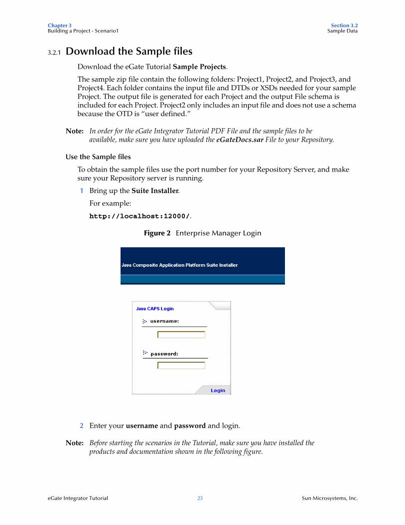
1 Bring up the Suite Installer.
For example:
http://localhost:12000/.
Figure 2 Enterprise Manager Login
2 Enter your username and password and login.
Note: Before starting the scenarios in the Tutorial, make sure you have installed the products and documentation shown in the following figure.
Chapter 3 Section 3.2Building a Project - Scenario1 Sample Data
eGate Integrator Tutorial 24 Sun Microsystems, Inc.
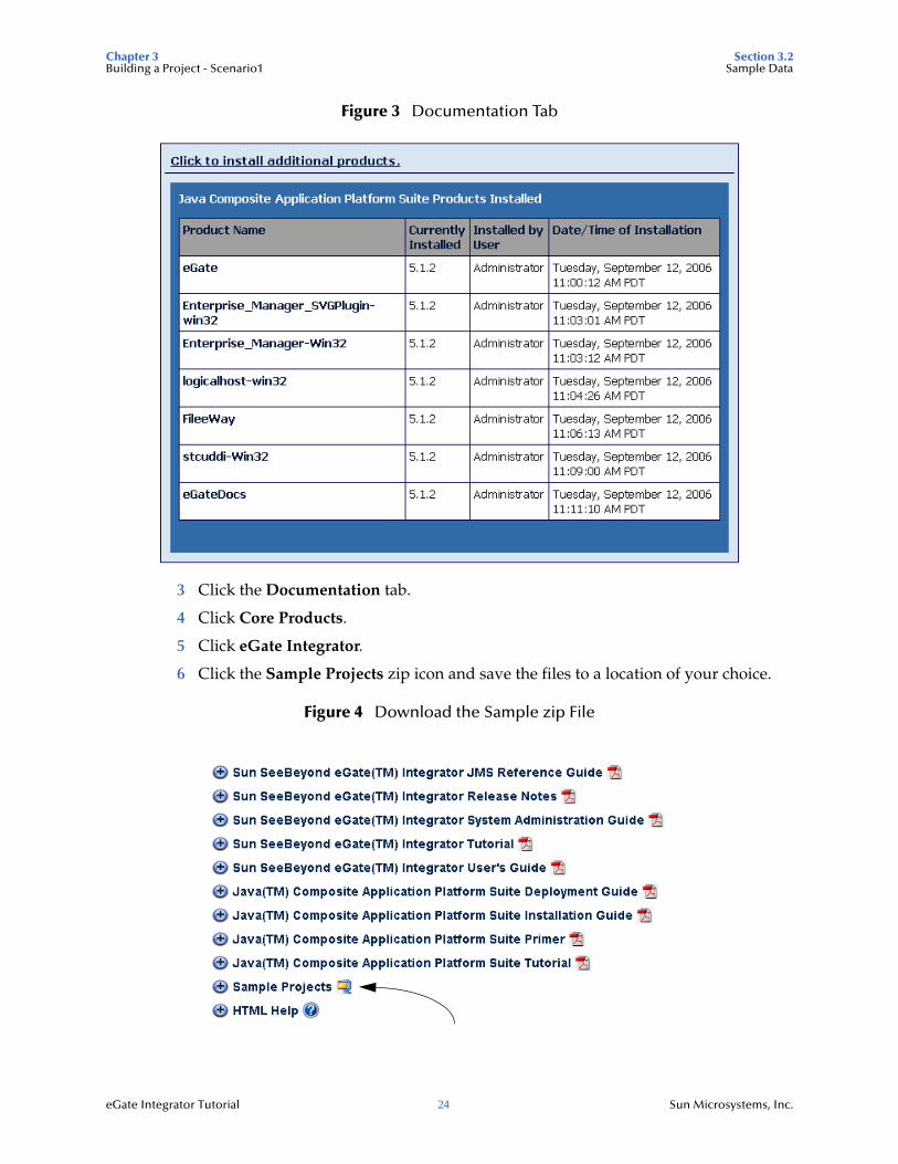
Figure 3 Documentation Tab
3 Click the Documentation tab.
4 Click Core Products.
5 Click eGate Integrator.
6 Click the Sample Projects zip icon and save the files to a location of your choice.
Figure 4 Download the Sample zip File
Chapter 3 Section 3.2Building a Project - Scenario1 Sample Data
eGate Integrator Tutorial 25 Sun Microsystems, Inc.
The zip File contains four zip folders: Project1.zip, Project2.zip, Project3.zip, and Project4.zip. After unzipping the eGate_Sample.zip, unzip the four zipped Project folders (The Project folders may appear as empty folders before each Project is unzipped).
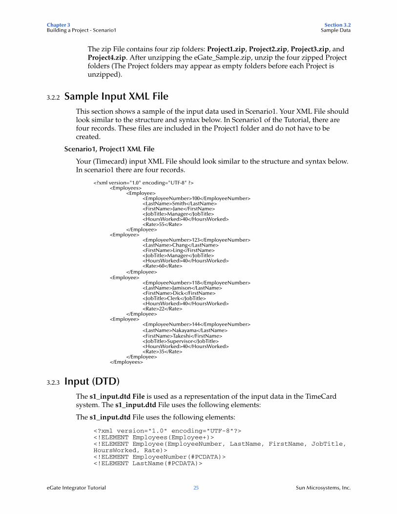
3.2.2 Sample Input XML FileThis section shows a sample of the input data used in Scenario1. Your XML File should look similar to the structure and syntax below. In Scenario1 of the Tutorial, there are four records. These files are included in the Project1 folder and do not have to be created.
Scenario1, Project1 XML File
Your (Timecard) input XML File should look similar to the structure and syntax below. In scenario1 there are four records.
<?xml version="1.0" encoding="UTF-8" ?> <Employees>
<Employee> <EmployeeNumber>100</EmployeeNumber> <LastName>Smith</LastName> <FirstName>Jane</FirstName> <JobTitle>Manager</JobTitle> <HoursWorked>40</HoursWorked> <Rate>55</Rate>
</Employee> <Employee>
<EmployeeNumber>123</EmployeeNumber> <LastName>Chang</LastName> <FirstName>Ling</FirstName> <JobTitle>Manager</JobTitle> <HoursWorked>40</HoursWorked> <Rate>60</Rate>
</Employee> <Employee>
<EmployeeNumber>118</EmployeeNumber> <LastName>Jamison</LastName> <FirstName>Dick</FirstName> <JobTitle>Clerk</JobTitle> <HoursWorked>40</HoursWorked> <Rate>22</Rate>
</Employee> <Employee>
<EmployeeNumber>144</EmployeeNumber> <LastName>Nakayama</LastName> <FirstName>Takeshi</FirstName> <JobTitle>Supervisor</JobTitle> <HoursWorked>40</HoursWorked> <Rate>35</Rate>
</Employee> </Employees>
3.2.3 Input (DTD)The s1_input.dtd File is used as a representation of the input data in the TimeCard system. The s1_input.dtd File uses the following elements:
The s1_input.dtd File uses the following elements:
<?xml version="1.0" encoding="UTF-8"?><!ELEMENT Employees(Employee+)><!ELEMENT Employee(EmployeeNumber, LastName, FirstName, JobTitle, HoursWorked, Rate)><!ELEMENT EmployeeNumber(#PCDATA)><!ELEMENT LastName(#PCDATA)>
Chapter 3 Section 3.3Building a Project - Scenario1 Business Challenge
eGate Integrator Tutorial 26 Sun Microsystems, Inc.
<!ELEMENT FirstName(#PCDATA)><!ELEMENT JobTitle(#PCDATA)><!ELEMENT HoursWorked(#PCDATA)><!ELEMENT Rate (#PCDATA) >
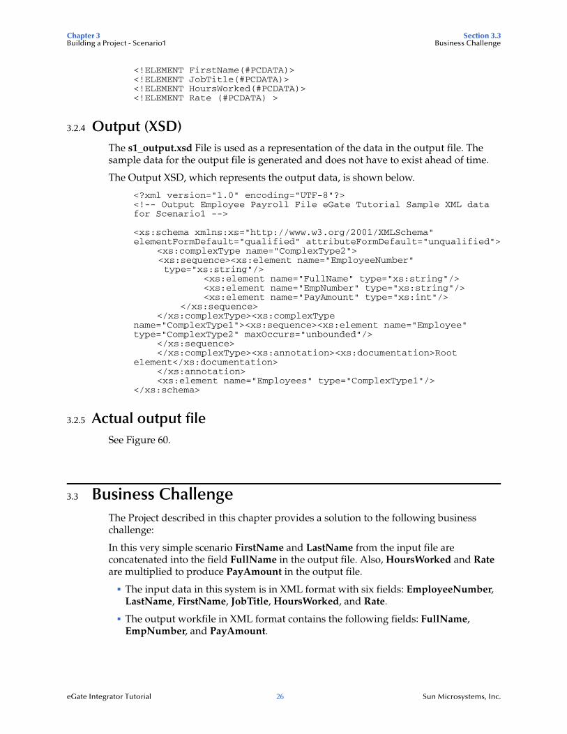
3.2.4 Output (XSD)The s1_output.xsd File is used as a representation of the data in the output file. The sample data for the output file is generated and does not have to exist ahead of time.
The Output XSD, which represents the output data, is shown below.
<?xml version="1.0" encoding="UTF-8"?><!-- Output Employee Payroll File eGate Tutorial Sample XML data for Scenario1 -->
<xs:schema xmlns:xs="http://www.w3.org/2001/XMLSchema" elementFormDefault="qualified" attributeFormDefault="unqualified">
<xs:complexType name="ComplexType2"> <xs:sequence><xs:element name="EmployeeNumber" type="xs:string"/>
<xs:element name="FullName" type="xs:string"/><xs:element name="EmpNumber" type="xs:string"/><xs:element name="PayAmount" type="xs:int"/>
</xs:sequence></xs:complexType><xs:complexType
name="ComplexType1"><xs:sequence><xs:element name="Employee" type="ComplexType2" maxOccurs="unbounded"/>
</xs:sequence></xs:complexType><xs:annotation><xs:documentation>Root
element</xs:documentation></xs:annotation><xs:element name="Employees" type="ComplexType1"/>
</xs:schema>
3.2.5 Actual output fileSee Figure 60.
3.3 Business ChallengeThe Project described in this chapter provides a solution to the following business challenge:
In this very simple scenario FirstName and LastName from the input file are concatenated into the field FullName in the output file. Also, HoursWorked and Rate are multiplied to produce PayAmount in the output file.
The input data in this system is in XML format with six fields: EmployeeNumber, LastName, FirstName, JobTitle, HoursWorked, and Rate.
The output workfile in XML format contains the following fields: FullName, EmpNumber, and PayAmount.
Chapter 3 Section 3.4Building a Project - Scenario1 Project Description
eGate Integrator Tutorial 27 Sun Microsystems, Inc.
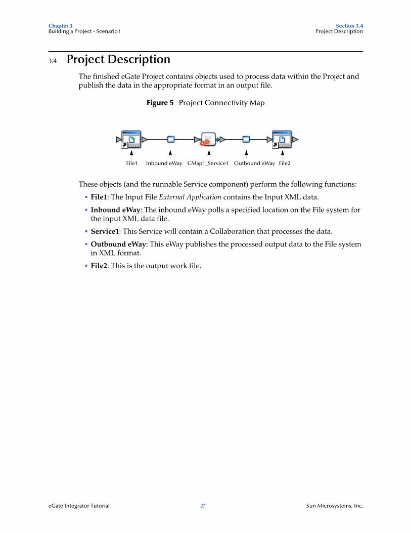
3.4 Project DescriptionThe finished eGate Project contains objects used to process data within the Project and publish the data in the appropriate format in an output file.
Figure 5 Project Connectivity Map
These objects (and the runnable Service component) perform the following functions:
File1: The Input File External Application contains the Input XML data.
Inbound eWay: The inbound eWay polls a specified location on the File system for the input XML data file.
Service1: This Service will contain a Collaboration that processes the data.
Outbound eWay: This eWay publishes the processed output data to the File system in XML format.
File2: This is the output work file.
File1 CMap1_Service1 File2Inbound eWay Outbound eWay
Chapter 3 Section 3.5Building a Project - Scenario1 Start Repository Server and Enterprise Designer
eGate Integrator Tutorial 28 Sun Microsystems, Inc.
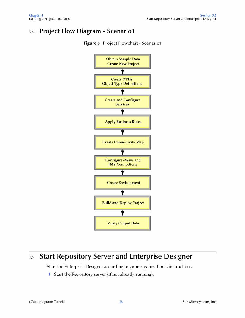
3.4.1 Project Flow Diagram - Scenario1
Figure 6 Project Flowchart - Scenario1
3.5 Start Repository Server and Enterprise DesignerStart the Enterprise Designer according to your organization’s instructions.
1 Start the Repository server (if not already running).
Obtain Sample DataCreate New Project
Create OTDsObject Type Definitions
Apply Business Rules
Create Connectivity Map
Configure eWays andJMS Connections
Create Environment
Build and Deploy Project
Verify Output Data
Create and ConfigureServices
Chapter 3 Section 3.6Building a Project - Scenario1 Create a New Project
eGate Integrator Tutorial 29 Sun Microsystems, Inc.
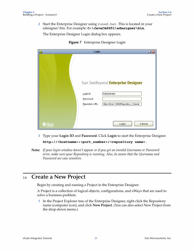
2 Start the Enterprise Designer using runed.bat. This is located in your edesigner\bin. For example: C:\JavaCAPS51\edesigner\bin.
The Enterprise Designer Login dialog box appears.
Figure 7 Enterprise Designer Login
3 Type your Login ID and Password. Click Login to start the Enterprise Designer.
http://<hostname>:<port_number>/<repository name>.
Note: If your login window doesn’t appear or if you get an invalid Username or Password error, make sure your Repository is running. Also, be aware that the Username and Password are case sensitive.
3.6 Create a New ProjectBegin by creating and naming a Project in the Enterprise Designer.
A Project is a collection of logical objects, configurations, and eWays that are used to solve a business problem.
1 In the Project Explorer tree of the Enterprise Designer, right-click the Repository name (computer icon), and click New Project. (You can also select New Project from the drop-down menu.)
Chapter 3 Section 3.6Building a Project - Scenario1 Create a New Project
eGate Integrator Tutorial 30 Sun Microsystems, Inc.
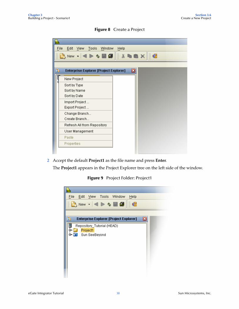
Figure 8 Create a Project
2 Accept the default Project1 as the file name and press Enter.
The Project1 appears in the Project Explorer tree on the left side of the window.
Figure 9 Project Folder: Project1
Chapter 3 Section 3.7Building a Project - Scenario1 Create a New Object Type Definition
eGate Integrator Tutorial 31 Sun Microsystems, Inc.
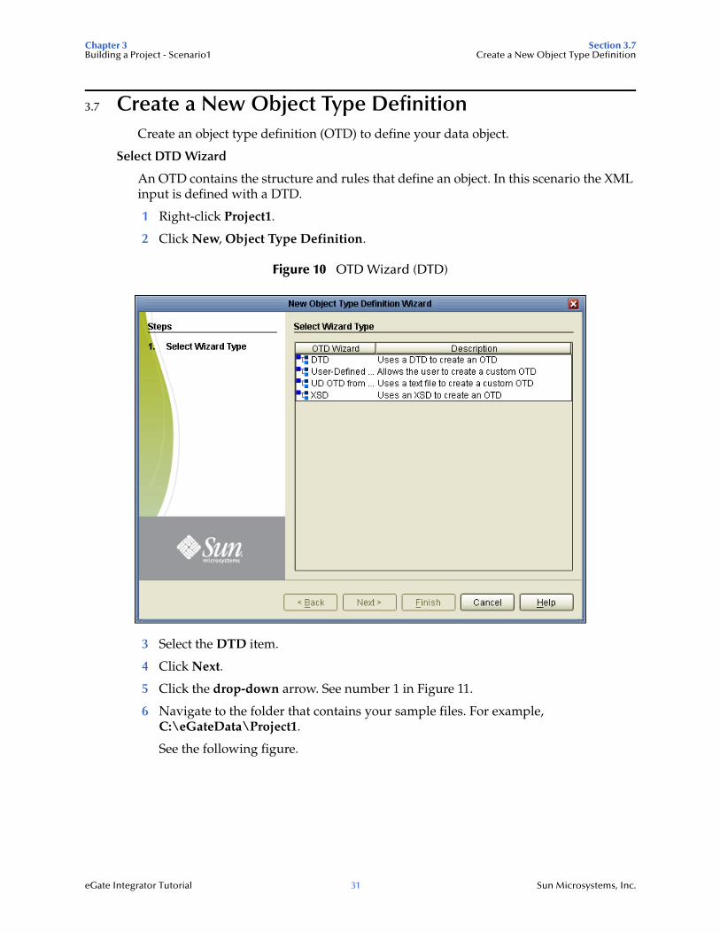
3.7 Create a New Object Type DefinitionCreate an object type definition (OTD) to define your data object.
Select DTD Wizard
An OTD contains the structure and rules that define an object. In this scenario the XML input is defined with a DTD.
1 Right-click Project1.
2 Click New, Object Type Definition.
Figure 10 OTD Wizard (DTD)
3 Select the DTD item.
4 Click Next.
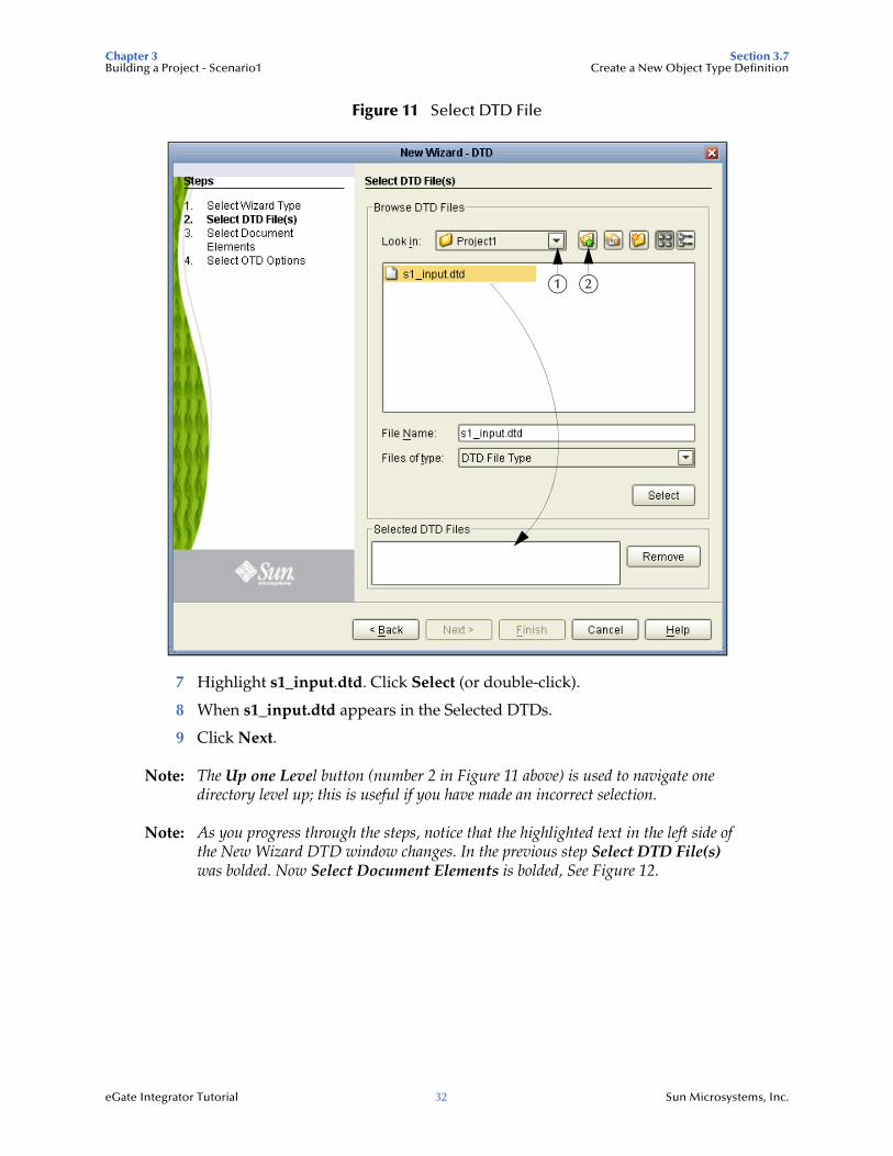
5 Click the drop-down arrow. See number 1 in Figure 11.
6 Navigate to the folder that contains your sample files. For example, C:\eGateData\Project1.
See the following figure.
Chapter 3 Section 3.7Building a Project - Scenario1 Create a New Object Type Definition
eGate Integrator Tutorial 32 Sun Microsystems, Inc.
Figure 11 Select DTD File
7 Highlight s1_input.dtd. Click Select (or double-click).
8 When s1_input.dtd appears in the Selected DTDs.
9 Click Next.
Note: The Up one Level button (number 2 in Figure 11 above) is used to navigate one directory level up; this is useful if you have made an incorrect selection.
Note: As you progress through the steps, notice that the highlighted text in the left side of the New Wizard DTD window changes. In the previous step Select DTD File(s) was bolded. Now Select Document Elements is bolded, See Figure 12.
21
Chapter 3 Section 3.7Building a Project - Scenario1 Create a New Object Type Definition
eGate Integrator Tutorial 33 Sun Microsystems, Inc.
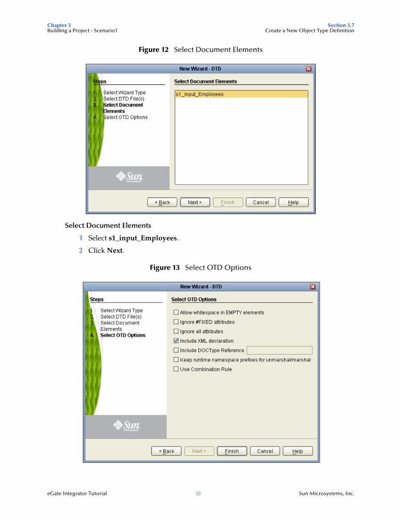
Figure 12 Select Document Elements
Select Document Elements
1 Select s1_input_Employees.
2 Click Next.
Figure 13 Select OTD Options

Chapter 3 Section 3.7Building a Project - Scenario1 Create a New Object Type Definition
eGate Integrator Tutorial 34 Sun Microsystems, Inc.
3 Click Finish (accepting the defaults).
The OTD Editor window opens. See Figure 17.
4 On the File toolbar, click Save.
Note: Save saves all your changes in your current open editor while Save All saves all changes across all editors, including changes in the environments.
The OTD Editor provides the developer with a graphical representation of the structure of the data.
Select XSD Wizard
In this scenario the XML output is defined with an XML schema definition (XSD).
1 Right-click Project1.
2 Click New, Object Type Definition.
3 This time select the XSD wizard and click Next.
The XSD wizard appears.
4 Navigate to and select s1_output.xsd.
Figure 14 OTD Wizard (XSD)
5 Double-click the output schema and click Next.
Chapter 3 Section 3.7Building a Project - Scenario1 Create a New Object Type Definition
eGate Integrator Tutorial 35 Sun Microsystems, Inc.
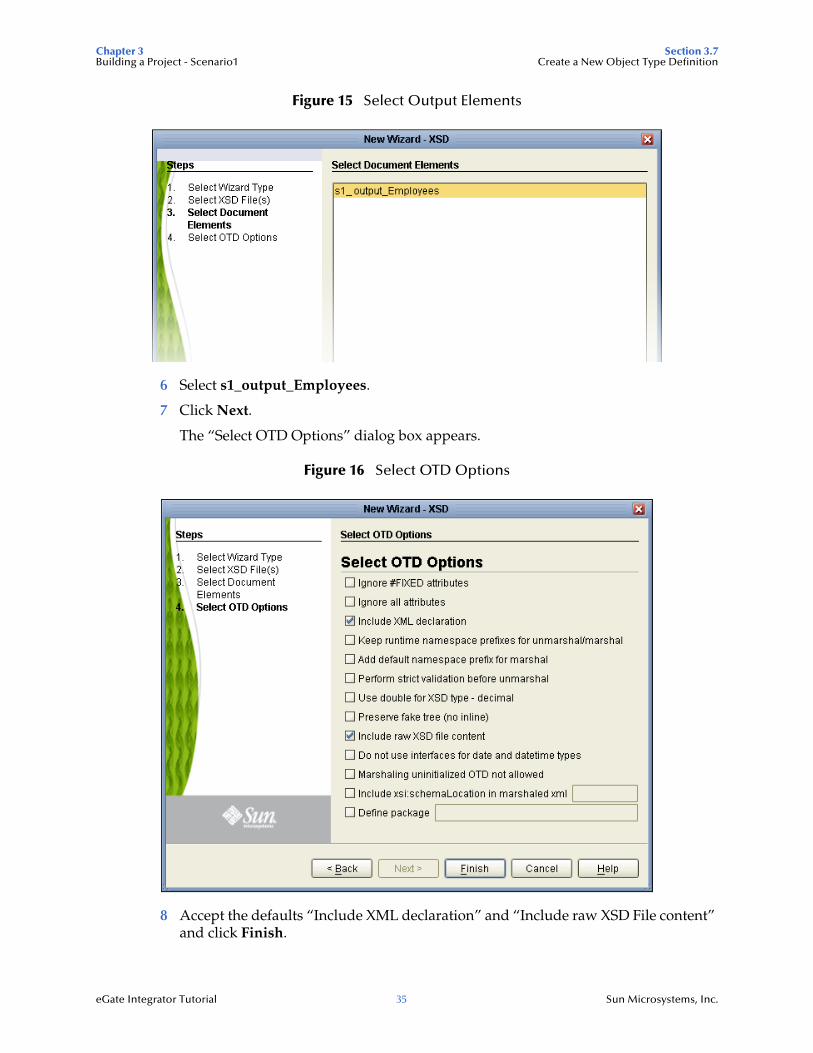
Figure 15 Select Output Elements
6 Select s1_output_Employees.
7 Click Next.
The “Select OTD Options” dialog box appears.
Figure 16 Select OTD Options
8 Accept the defaults “Include XML declaration” and “Include raw XSD File content” and click Finish.
Chapter 3 Section 3.8Building a Project - Scenario1 Configure the Services
eGate Integrator Tutorial 36 Sun Microsystems, Inc.
Figure 17 OTD Editor Input
9 Click Close All from the Window menu bar. (This closes all open windows. Do not close the Enterprise Designer.)
10 Click Save All.
3.8 Configure the ServicesUse Service wizards in the following steps to configure your Collaboration. A Collaboration describes your data and connections and contains information about message routing and transformation logic.
3.8.1 Configure Service1Configure a Collaboration (Java) definition.
Enter a Collaboration Name
1 Right-click Project1.
2 Click New, Collaboration Definition (Java).
The Collaboration Definition Wizard (Java) appears.
Chapter 3 Section 3.8Building a Project - Scenario1 Configure the Services
eGate Integrator Tutorial 37 Sun Microsystems, Inc.
Figure 18 New Collaboration Definition (Java) Name
Accept the default name for the Collaboration Definition, Collaboration_1. (Also accept the Web Service Type default, “Existing: Implement an existing Web Service operation.”)
3 Click Next.

Chapter 3 Section 3.8Building a Project - Scenario1 Configure the Services
eGate Integrator Tutorial 38 Sun Microsystems, Inc.
Figure 19 Select Web Service File Receive
Create a File Read Web Service
Web services enable communication between diverse applications using the Internet. Select a web service to “implement” a file-read. Refer to eGate Integrator User’s Guide for information about web services.
1 Double-click Sun SeeBeyond.
2 Double-click eWays. eWays are message end points that connect to an external service provider to enable the sending and receiving of messages.
3 Double-click File.
4 Double-click FileClient.
5 Click receive. Notice that receive appears in the Name field as shown in the following Figure 20.
(FileClient receive is used for file-based eWays to bring data in.)
Chapter 3 Section 3.8Building a Project - Scenario1 Configure the Services
eGate Integrator Tutorial 39 Sun Microsystems, Inc.
Figure 20 New Collaboration Web Service Interface
6 Click Next when “receive” appears in the File Name field.
Select an OTD for the outbound FileClient
First select the output FileClient OTD. (Its parameters are automatically defined.) Then, select the XML OTDs.
Chapter 3 Section 3.8Building a Project - Scenario1 Configure the Services
eGate Integrator Tutorial 40 Sun Microsystems, Inc.
Figure 21 Select FileClient OTD
1 Double-click Sun SeeBeyond.
2 Double-click eWays.
3 Double-click File.
4 Double-click FileClient.
This adds the FileClient_1 OTD to the list. See the following Figure 22.
Chapter 3 Section 3.8Building a Project - Scenario1 Configure the Services
eGate Integrator Tutorial 41 Sun Microsystems, Inc.
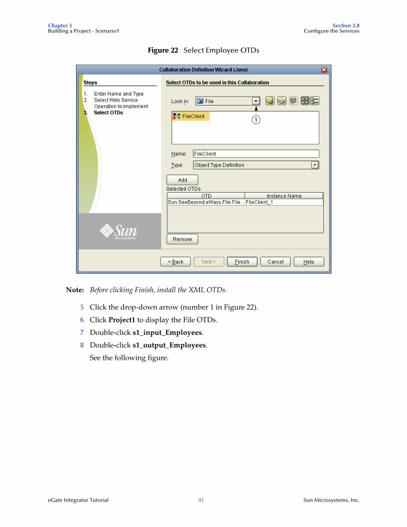
Figure 22 Select Employee OTDs
Note: Before clicking Finish, install the XML OTDs.
5 Click the drop-down arrow (number 1 in Figure 22).
6 Click Project1 to display the File OTDs.
7 Double-click s1_input_Employees.
8 Double-click s1_output_Employees.
See the following figure.
1
Chapter 3 Section 3.8Building a Project - Scenario1 Configure the Services
eGate Integrator Tutorial 42 Sun Microsystems, Inc.
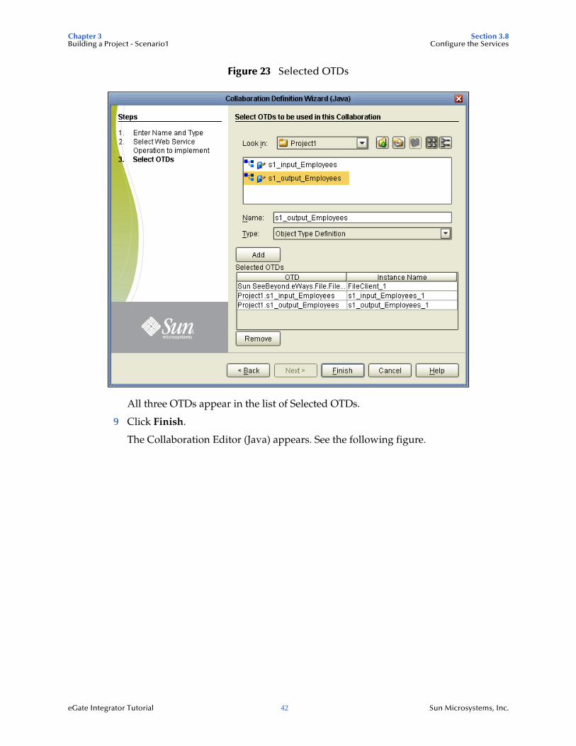
Figure 23 Selected OTDs
All three OTDs appear in the list of Selected OTDs.
9 Click Finish.
The Collaboration Editor (Java) appears. See the following figure.
Chapter 3 Section 3.9Building a Project - Scenario1 Apply Business Rules
eGate Integrator Tutorial 43 Sun Microsystems, Inc.
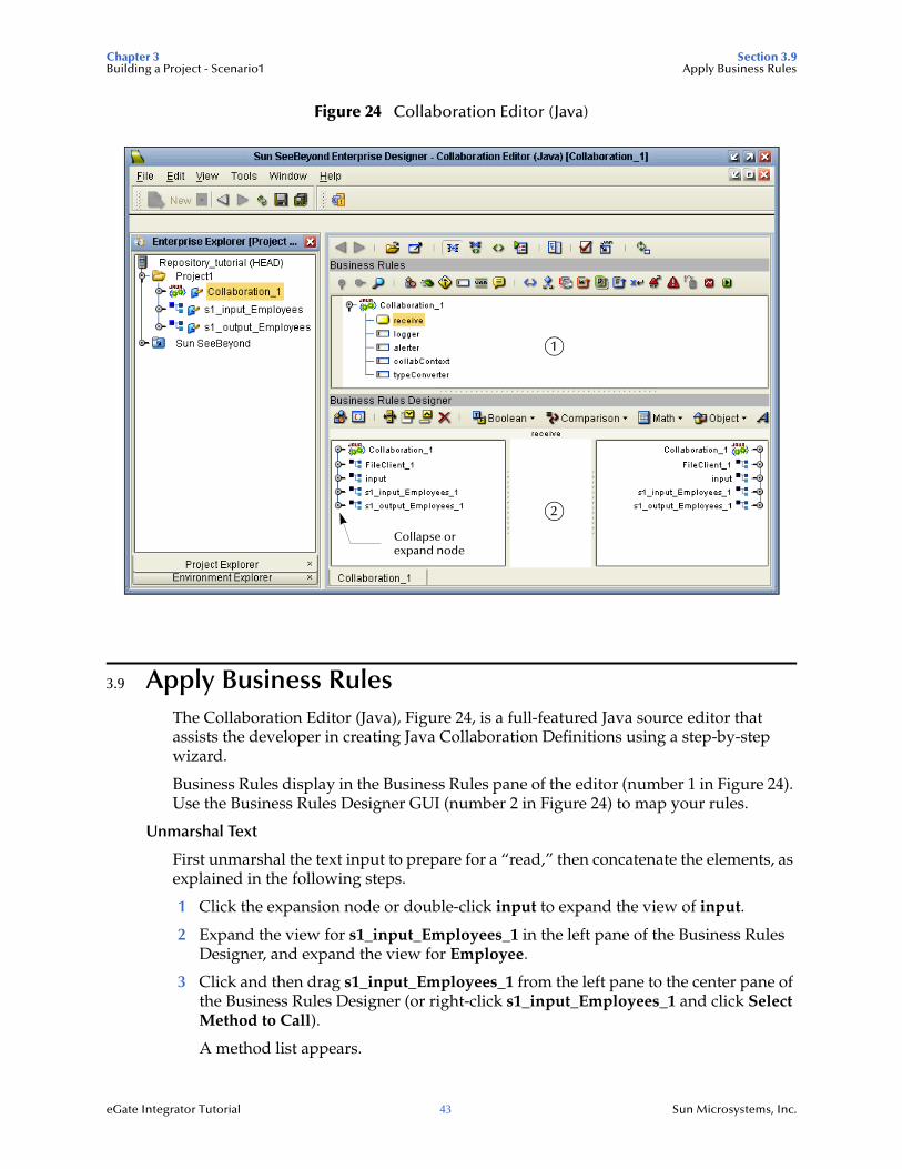
Figure 24 Collaboration Editor (Java)
3.9 Apply Business RulesThe Collaboration Editor (Java), Figure 24, is a full-featured Java source editor that assists the developer in creating Java Collaboration Definitions using a step-by-step wizard.
Business Rules display in the Business Rules pane of the editor (number 1 in Figure 24). Use the Business Rules Designer GUI (number 2 in Figure 24) to map your rules.
Unmarshal Text
First unmarshal the text input to prepare for a “read,” then concatenate the elements, as explained in the following steps.
1 Click the expansion node or double-click input to expand the view of input.
2 Expand the view for s1_input_Employees_1 in the left pane of the Business Rules Designer, and expand the view for Employee.
3 Click and then drag s1_input_Employees_1 from the left pane to the center pane of the Business Rules Designer (or right-click s1_input_Employees_1 and click Select Method to Call).
A method list appears.
1
2
Collapse or expand node
Chapter 3 Section 3.9Building a Project - Scenario1 Apply Business Rules
eGate Integrator Tutorial 44 Sun Microsystems, Inc.
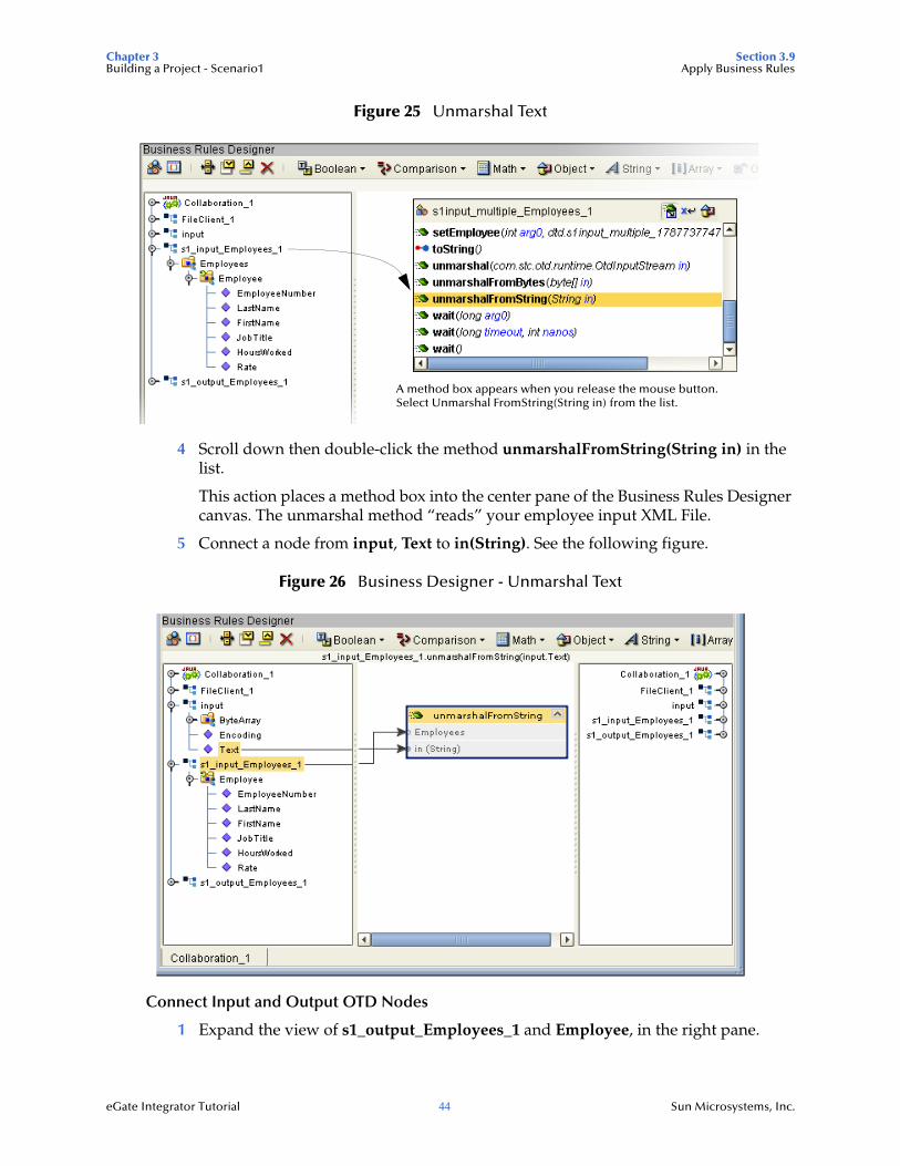
Figure 25 Unmarshal Text
4 Scroll down then double-click the method unmarshalFromString(String in) in the list.
This action places a method box into the center pane of the Business Rules Designer canvas. The unmarshal method “reads” your employee input XML File.
5 Connect a node from input, Text to in(String). See the following figure.
Figure 26 Business Designer - Unmarshal Text
Connect Input and Output OTD Nodes
1 Expand the view of s1_output_Employees_1 and Employee, in the right pane.
A method box appears when you release the mouse button.Select Unmarshal FromString(String in) from the list.
Chapter 3 Section 3.9Building a Project - Scenario1 Apply Business Rules
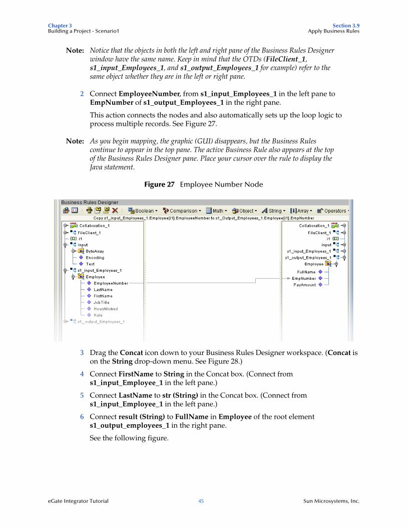
eGate Integrator Tutorial 45 Sun Microsystems, Inc.
Note: Notice that the objects in both the left and right pane of the Business Rules Designer window have the same name. Keep in mind that the OTDs (FileClient_1, s1_input_Employees_1, and s1_output_Employees_1 for example) refer to the same object whether they are in the left or right pane.
2 Connect EmployeeNumber, from s1_input_Employees_1 in the left pane to EmpNumber of s1_output_Employees_1 in the right pane.
This action connects the nodes and also automatically sets up the loop logic to process multiple records. See Figure 27.
Note: As you begin mapping, the graphic (GUI) disappears, but the Business Rules continue to appear in the top pane. The active Business Rule also appears at the top of the Business Rules Designer pane. Place your cursor over the rule to display the Java statement.
Figure 27 Employee Number Node
3 Drag the Concat icon down to your Business Rules Designer workspace. (Concat is on the String drop-down menu. See Figure 28.)
4 Connect FirstName to String in the Concat box. (Connect from s1_input_Employee_1 in the left pane.)
5 Connect LastName to str (String) in the Concat box. (Connect from s1_input_Employee_1 in the left pane.)
6 Connect result (String) to FullName in Employee of the root element s1_output_employees_1 in the right pane.
See the following figure.
Chapter 3 Section 3.9Building a Project - Scenario1 Apply Business Rules
eGate Integrator Tutorial 46 Sun Microsystems, Inc.
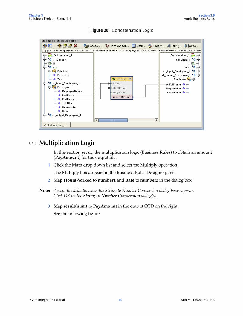
Figure 28 Concatenation Logic
3.9.1 Multiplication LogicIn this section set up the multiplication logic (Business Rules) to obtain an amount (PayAmount) for the output file.
1 Click the Math drop down list and select the Multiply operation.
The Multiply box appears in the Business Rules Designer pane.
2 Map HoursWorked to number1 and Rate to number2 in the dialog box.
Note: Accept the defaults when the String to Number Conversion dialog boxes appear. Click OK on the String to Number Conversion dialog(s).
3 Map result(num) to PayAmount in the output OTD on the right.
See the following figure.
Chapter 3 Section 3.9Building a Project - Scenario1 Apply Business Rules
eGate Integrator Tutorial 47 Sun Microsystems, Inc.
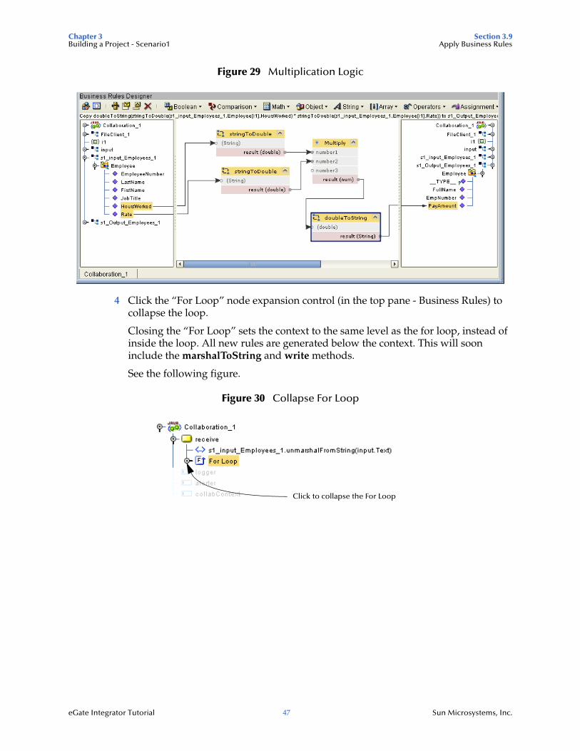
Figure 29 Multiplication Logic
4 Click the “For Loop” node expansion control (in the top pane - Business Rules) to collapse the loop.
Closing the “For Loop” sets the context to the same level as the for loop, instead of inside the loop. All new rules are generated below the context. This will soon include the marshalToString and write methods.
See the following figure.
Figure 30 Collapse For Loop
Click to collapse the For Loop
Chapter 3 Section 3.9Building a Project - Scenario1 Apply Business Rules
eGate Integrator Tutorial 48 Sun Microsystems, Inc.
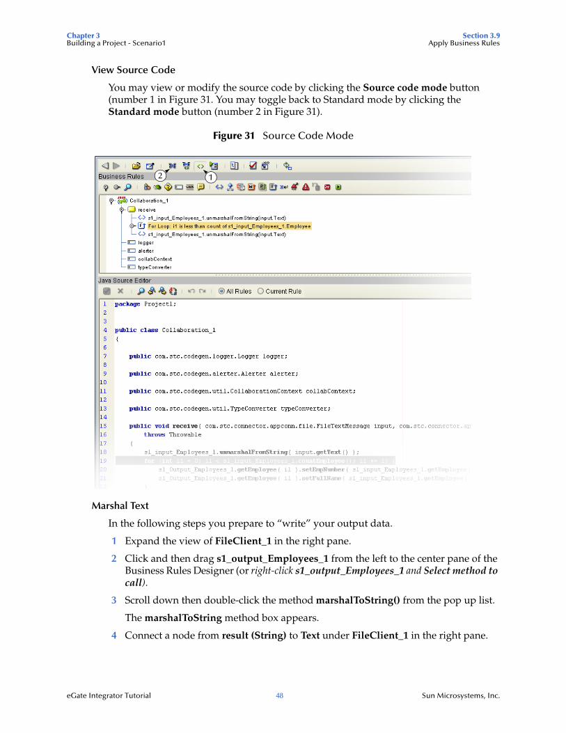
View Source Code
You may view or modify the source code by clicking the Source code mode button (number 1 in Figure 31. You may toggle back to Standard mode by clicking the Standard mode button (number 2 in Figure 31).
Figure 31 Source Code Mode
Marshal Text
In the following steps you prepare to “write” your output data.
1 Expand the view of FileClient_1 in the right pane.
2 Click and then drag s1_output_Employees_1 from the left to the center pane of the Business Rules Designer (or right-click s1_output_Employees_1 and Select method to call).
3 Scroll down then double-click the method marshalToString() from the pop up list.
The marshalToString method box appears.
4 Connect a node from result (String) to Text under FileClient_1 in the right pane.
2 1
Chapter 3 Section 3.9Building a Project - Scenario1 Apply Business Rules
eGate Integrator Tutorial 49 Sun Microsystems, Inc.
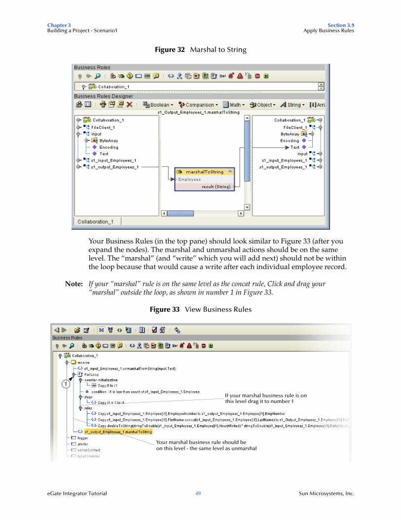
Figure 32 Marshal to String
Your Business Rules (in the top pane) should look similar to Figure 33 (after you expand the nodes). The marshal and unmarshal actions should be on the same level. The “marshal” (and “write” which you will add next) should not be within the loop because that would cause a write after each individual employee record.
Note: If your “marshal” rule is on the same level as the concat rule, Click and drag your “marshal” outside the loop, as shown in number 1 in Figure 33.
Figure 33 View Business Rules
1
If your marshal business rule is on
Your marshal business rule should beon this level - the same level as unmarshal
this level drag it to number 1
Chapter 3 Section 3.10Building a Project - Scenario1 Create a Connectivity Map
eGate Integrator Tutorial 50 Sun Microsystems, Inc.
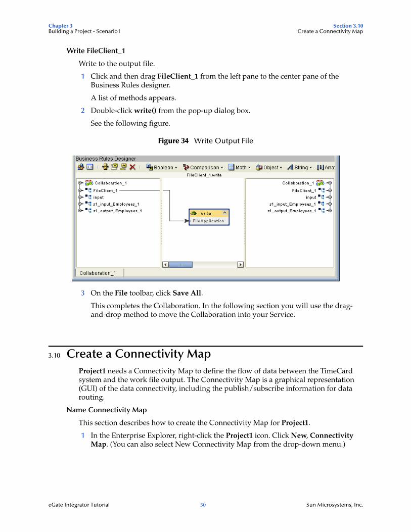
Write FileClient_1
Write to the output file.
1 Click and then drag FileClient_1 from the left pane to the center pane of the Business Rules designer.
A list of methods appears.
2 Double-click write() from the pop-up dialog box.
See the following figure.
Figure 34 Write Output File
3 On the File toolbar, click Save All.
This completes the Collaboration. In the following section you will use the drag-and-drop method to move the Collaboration into your Service.
3.10 Create a Connectivity MapProject1 needs a Connectivity Map to define the flow of data between the TimeCard system and the work file output. The Connectivity Map is a graphical representation (GUI) of the data connectivity, including the publish/subscribe information for data routing.
Name Connectivity Map
This section describes how to create the Connectivity Map for Project1.
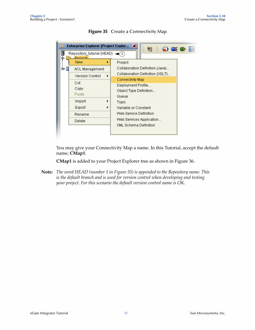
1 In the Enterprise Explorer, right-click the Project1 icon. Click New, Connectivity Map. (You can also select New Connectivity Map from the drop-down menu.)
Chapter 3 Section 3.10Building a Project - Scenario1 Create a Connectivity Map
eGate Integrator Tutorial 51 Sun Microsystems, Inc.
Figure 35 Create a Connectivity Map
You may give your Connectivity Map a name. In this Tutorial, accept the default name, CMap1.
CMap1 is added to your Project Explorer tree as shown in Figure 36.
Note: The word HEAD (number 1 in Figure 35) is appended to the Repository name. This is the default branch and is used for version control when developing and testing your project. For this scenario the default version control name is OK.
1
Chapter 3 Section 3.10Building a Project - Scenario1 Create a Connectivity Map
eGate Integrator Tutorial 52 Sun Microsystems, Inc.
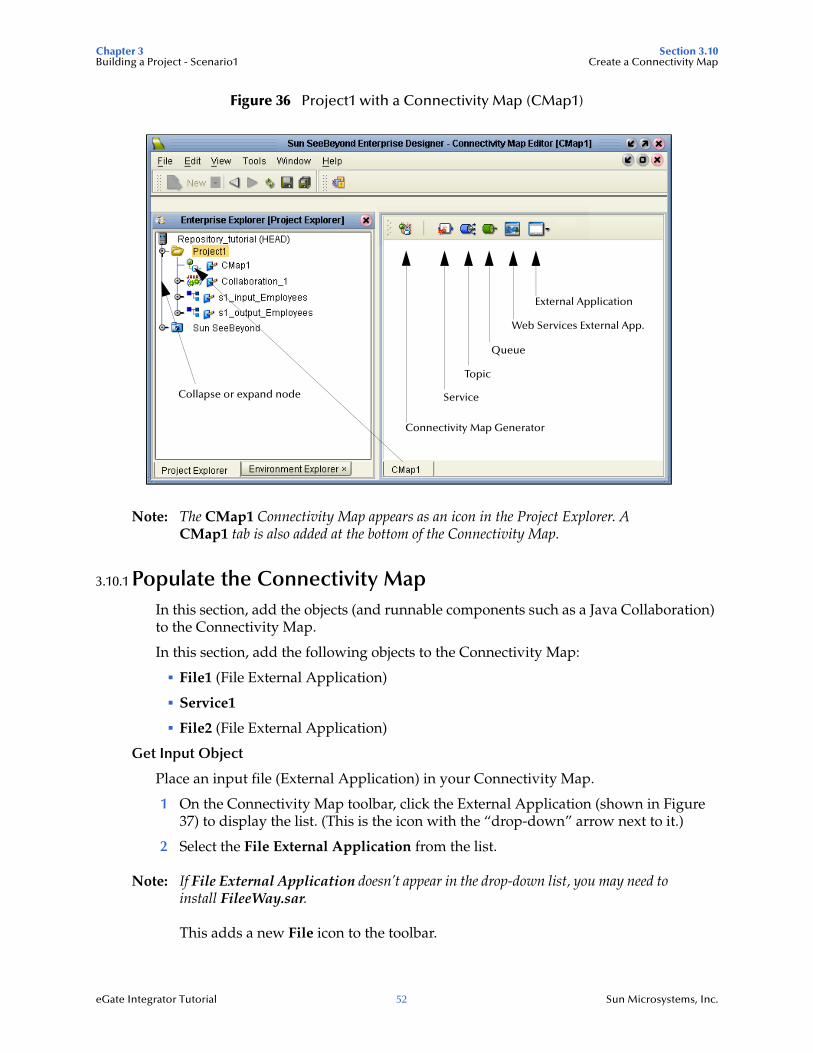
Figure 36 Project1 with a Connectivity Map (CMap1)
Note: The CMap1 Connectivity Map appears as an icon in the Project Explorer. A CMap1 tab is also added at the bottom of the Connectivity Map.
3.10.1 Populate the Connectivity MapIn this section, add the objects (and runnable components such as a Java Collaboration) to the Connectivity Map.
In this section, add the following objects to the Connectivity Map:
File1 (File External Application)
Service1
File2 (File External Application)
Get Input Object
Place an input file (External Application) in your Connectivity Map.
1 On the Connectivity Map toolbar, click the External Application (shown in Figure 37) to display the list. (This is the icon with the “drop-down” arrow next to it.)
2 Select the File External Application from the list.
Note: If File External Application doesn’t appear in the drop-down list, you may need to install FileeWay.sar.
This adds a new File icon to the toolbar.
External Application
Web Services External App.
Queue
Topic
ServiceCollapse or expand node
Connectivity Map Generator
Chapter 3 Section 3.11Building a Project - Scenario1 Apply the Collaboration
eGate Integrator Tutorial 53 Sun Microsystems, Inc.
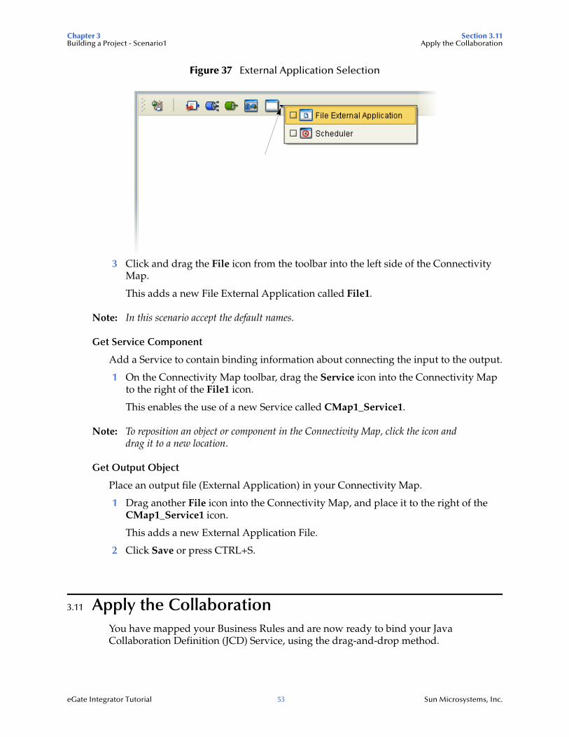
Figure 37 External Application Selection
3 Click and drag the File icon from the toolbar into the left side of the Connectivity Map.
This adds a new File External Application called File1.
Note: In this scenario accept the default names.
Get Service Component
Add a Service to contain binding information about connecting the input to the output.
1 On the Connectivity Map toolbar, drag the Service icon into the Connectivity Map to the right of the File1 icon.
This enables the use of a new Service called CMap1_Service1.
Note: To reposition an object or component in the Connectivity Map, click the icon and drag it to a new location.
Get Output Object
Place an output file (External Application) in your Connectivity Map.
1 Drag another File icon into the Connectivity Map, and place it to the right of the CMap1_Service1 icon.
This adds a new External Application File.
2 Click Save or press CTRL+S.
3.11 Apply the CollaborationYou have mapped your Business Rules and are now ready to bind your Java Collaboration Definition (JCD) Service, using the drag-and-drop method.
Chapter 3 Section 3.11Building a Project - Scenario1 Apply the Collaboration
eGate Integrator Tutorial 54 Sun Microsystems, Inc.
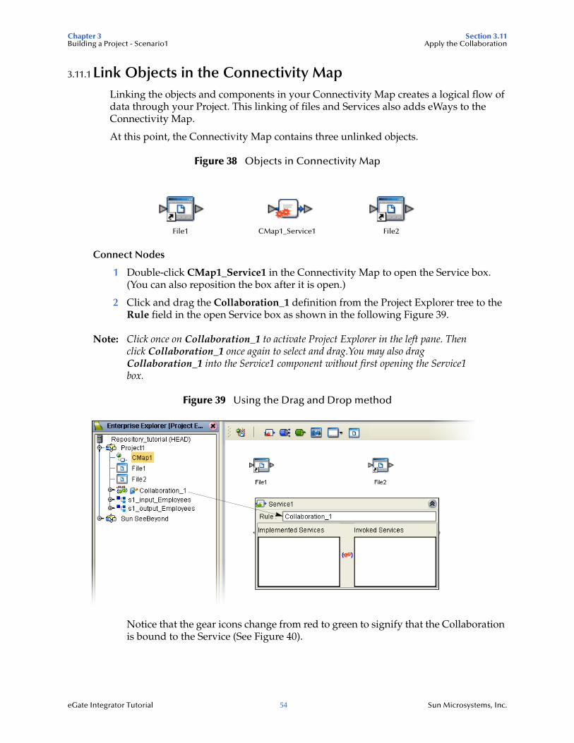
3.11.1 Link Objects in the Connectivity MapLinking the objects and components in your Connectivity Map creates a logical flow of data through your Project. This linking of files and Services also adds eWays to the Connectivity Map.
At this point, the Connectivity Map contains three unlinked objects.
Figure 38 Objects in Connectivity Map
Connect Nodes
1 Double-click CMap1_Service1 in the Connectivity Map to open the Service box. (You can also reposition the box after it is open.)
2 Click and drag the Collaboration_1 definition from the Project Explorer tree to the Rule field in the open Service box as shown in the following Figure 39.
Note: Click once on Collaboration_1 to activate Project Explorer in the left pane. Then click Collaboration_1 once again to select and drag.You may also drag Collaboration_1 into the Service1 component without first opening the Service1 box.
Figure 39 Using the Drag and Drop method
Notice that the gear icons change from red to green to signify that the Collaboration is bound to the Service (See Figure 40).
File1 CMap1_Service1 File2
Chapter 3 Section 3.11Building a Project - Scenario1 Apply the Collaboration
eGate Integrator Tutorial 55 Sun Microsystems, Inc.
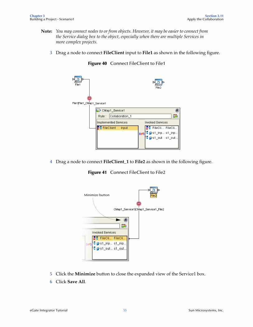
Note: You may connect nodes to or from objects. However, it may be easier to connect from the Service dialog box to the object, especially when there are multiple Services in more complex projects.
3 Drag a node to connect FileClient input to File1 as shown in the following figure.
Figure 40 Connect FileClient to File1
4 Drag a node to connect FileClient_1 to File2 as shown in the following figure.
Figure 41 Connect FileClient to File2
5 Click the Minimize button to close the expanded view of the Service1 box.
6 Click Save All.
Minimize button
Chapter 3 Section 3.12Building a Project - Scenario1 Configure the eWays
eGate Integrator Tutorial 56 Sun Microsystems, Inc.
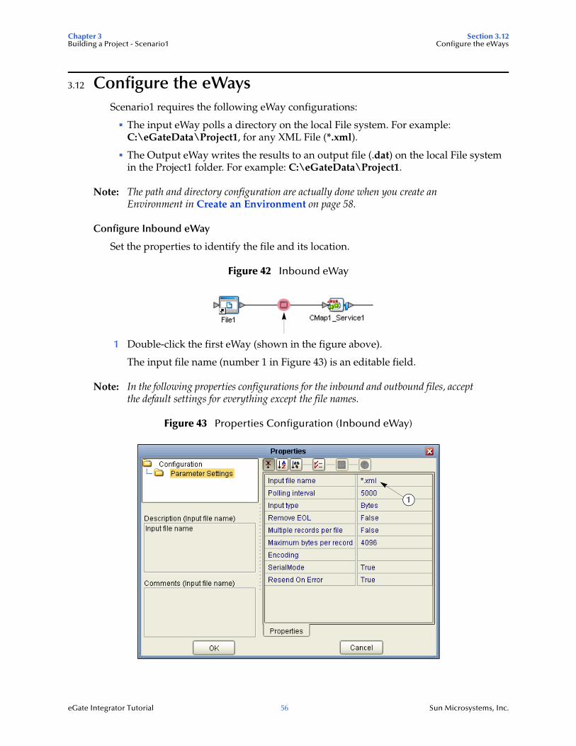
3.12 Configure the eWaysScenario1 requires the following eWay configurations:
The input eWay polls a directory on the local File system. For example: C:\eGateData\Project1, for any XML File (*.xml).
The Output eWay writes the results to an output file (.dat) on the local File system in the Project1 folder. For example: C:\eGateData\Project1.
Note: The path and directory configuration are actually done when you create an Environment in Create an Environment on page 58.
Configure Inbound eWay
Set the properties to identify the file and its location.
Figure 42 Inbound eWay
1 Double-click the first eWay (shown in the figure above).
The input file name (number 1 in Figure 43) is an editable field.
Note: In the following properties configurations for the inbound and outbound files, accept the default settings for everything except the file names.
Figure 43 Properties Configuration (Inbound eWay)
1
Chapter 3 Section 3.12Building a Project - Scenario1 Configure the eWays
eGate Integrator Tutorial 57 Sun Microsystems, Inc.
2 Click the Input File Name field and enter *.xml. The eWay reads any files with the .xml extension.
3 Click OK to close the Properties Dialog Box for the inbound eWay.
After the inbound eWay is set, the red circle in the graphic disappears.
Note: If the Polling interval value is left unchanged, the eWay polls the directory location every five seconds (5000 milliseconds).
Configure Outbound eWay
Set the properties to identify the file and its location.
1 Double-click the second eWay.
Figure 44 Outbound eWay
The Properties dialog box appears.
2 Name the output File: s1_output.dat (Scenario1 output).
After the outbound eWay is set, the link (red circle) in the graphic disappears.
Figure 45 Properties Configuration (Outbound eWay)
Note: Refer to “Multiple records per File (True or False)” on page 58.
3 Click OK to close the Properties Dialog Box for the outbound eWay and accept the default settings for the remaining properties.
Chapter 3 Section 3.13Building a Project - Scenario1 Create an Environment
eGate Integrator Tutorial 58 Sun Microsystems, Inc.
4 On the File toolbar, click Save All.
You have now configured both the input and output eWays and are ready to deploy your Project. You may skip to “Create an Environment” on page 58.
Multiple records per File (True or False)
This setting (refer to Figure 43 and Figure 45) specifies if multiple records are to be obtained or sent per file. Multiple records (messages) are generated per line up to the maximum bytes per record.
Inbound eWay
A True setting means that each separate line in the input file is treated as a separate message. Messages are generated up to the number specified in the Maximum bytes per record property.
A False setting means that the file is read as a block and represents a single message. This message can be treated as one “record” because our business rule contains the logic to loop through each record in the XML message.
Outbound eWay
This setting determines whether records are concatenated in a file. If no incrementer is used, the output file is overwritten with each message.
A True setting means that multiple messages are written to the same file. New messages are appended (concatenated) to the output file with each write().
A False setting means that only one message is written in one file. New messages are written to a different file (with the file number incremented if you use %d) with each write().
3.13 Create an EnvironmentAn Environment is a collection of physical resources and their configurations that are used to host Project objects. An Environment contains logical hosts and external systems.
Create a Logical Host and an External File System using Environment Explorer. First create an Environment. The Environment Explorer deploys resources required to implement a project and includes information about external systems that interact with eGate.
Add Logical Host and Servers
1 Click View on the Menu bar. Click Environment Explorer (or click the Environment Explorer tab).
2 Right-click the Repository name (computer icon). Click New, Environment.
3 Right-click Environment1 and rename it to Tutorial. Press Enter.
4 Right-click Tutorial. Click New, Logical Host.
Chapter 3 Section 3.13Building a Project - Scenario1 Create an Environment
eGate Integrator Tutorial 59 Sun Microsystems, Inc.
This creates a LogicalHost1 box in the right pane.
Add an Integration Server
The Integration Server is a J2EE software platform that houses the business logic container used to run Collaborations and JCA connectors (eWays).
1 Right-click LogicalHost1 in the Enterprise Explorer window. Click New, Sun SeeBeyond Integration Server.
IntegrationSvr1 appears in the LogicalHost1 box. Your Collaborations will be bound to this server.
Add a JMS IQ Manager
The JMS IQ Manager is a JMS-compliant, guaranteed delivery store, forwarding, and queueing Service.
Note: You would bind your Topics and Queues to this server if you had them. In Scenario1 there are no Topics or Queues; in Scenario2 you will use a Topic.
1 Right-click LogicalHost1 in the Enterprise Explorer window. Click New, Sun SeeBeyond JMS IQ Manager.
SBJMSIQMgr1 appears in the LogicalHost1 box.
Figure 46 Environment with Logicalhost
Add an External File System for the eWays
1 Right-click Tutorial Environment.
2 Click New, File External System.
Chapter 3 Section 3.13Building a Project - Scenario1 Create an Environment
eGate Integrator Tutorial 60 Sun Microsystems, Inc.
This creates a container in the Environment Editor to hold your File eWays. You will place both input and output files in this container.
3 Name the External System Input and Output files.
Figure 47 External files
4 Click OK.
Note: You may have to move a dialog (GUI) if it is blocking an underlying dialog in the designer canvas.
Your Environment Editor pane should look similar the following figure.
Figure 48 Environment Editor
Set Properties for External File System
Set the properties and parameter settings to show the directory data path.
1 Right-click Input and Output files in the left pane.
Chapter 3 Section 3.13Building a Project - Scenario1 Create an Environment
eGate Integrator Tutorial 61 Sun Microsystems, Inc.
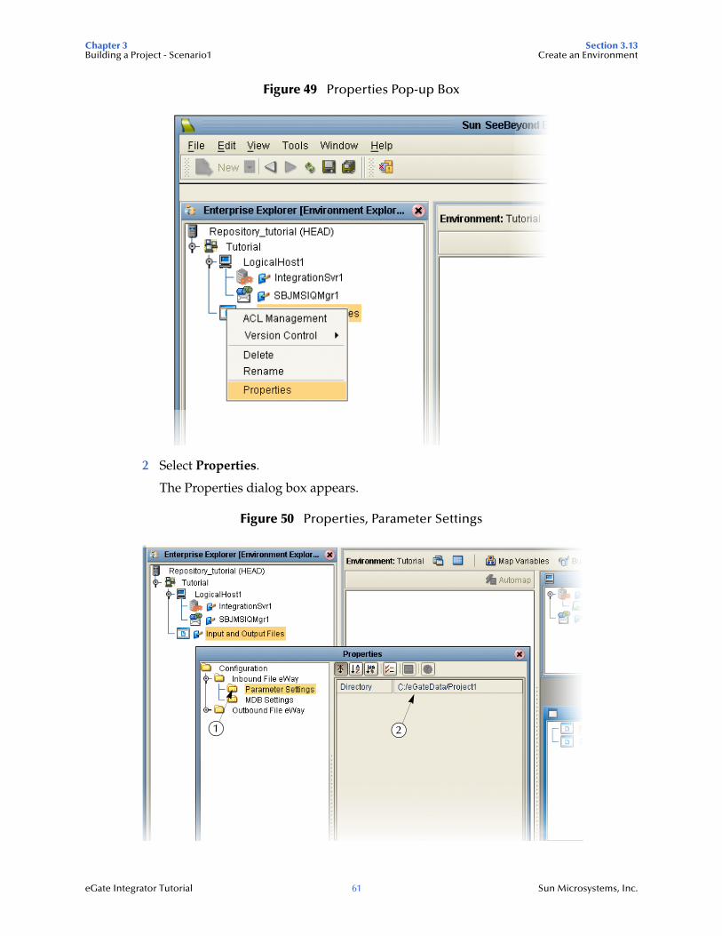
Figure 49 Properties Pop-up Box
2 Select Properties.
The Properties dialog box appears.
Figure 50 Properties, Parameter Settings
21
Chapter 3 Section 3.14Building a Project - Scenario1 Create the Deployment Profile
eGate Integrator Tutorial 62 Sun Microsystems, Inc.
3 Expand the view under Inbound File eWay.
4 Select Parameter Settings (number 1 in the previous figure).
5 Set the Directory path to point to your input data File (number 2 in the previous figure).
6 Click OK.
7 Repeat these steps for your Outbound File eWay.
8 Click Save.
Note: Enter the directory paths only, not including the file name. The output data file does not have to already exist. It will be created. The input and/or output directories (including all required sub-directories) will also be created when necessary – not necessary in this tutorial – by the File External System during runtime.
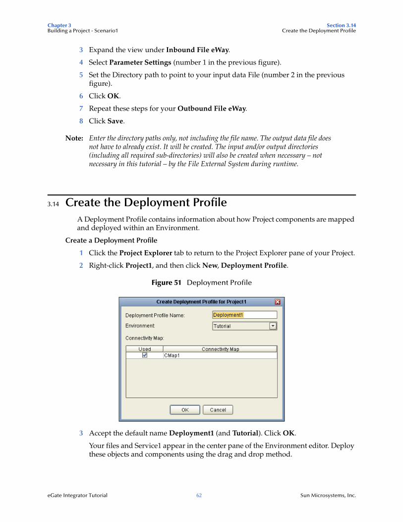
3.14 Create the Deployment ProfileA Deployment Profile contains information about how Project components are mapped and deployed within an Environment.
Create a Deployment Profile
1 Click the Project Explorer tab to return to the Project Explorer pane of your Project.
2 Right-click Project1, and then click New, Deployment Profile.
Figure 51 Deployment Profile
3 Accept the default name Deployment1 (and Tutorial). Click OK.
Your files and Service1 appear in the center pane of the Environment editor. Deploy these objects and components using the drag and drop method.
Chapter 3 Section 3.14Building a Project - Scenario1 Create the Deployment Profile
eGate Integrator Tutorial 63 Sun Microsystems, Inc.
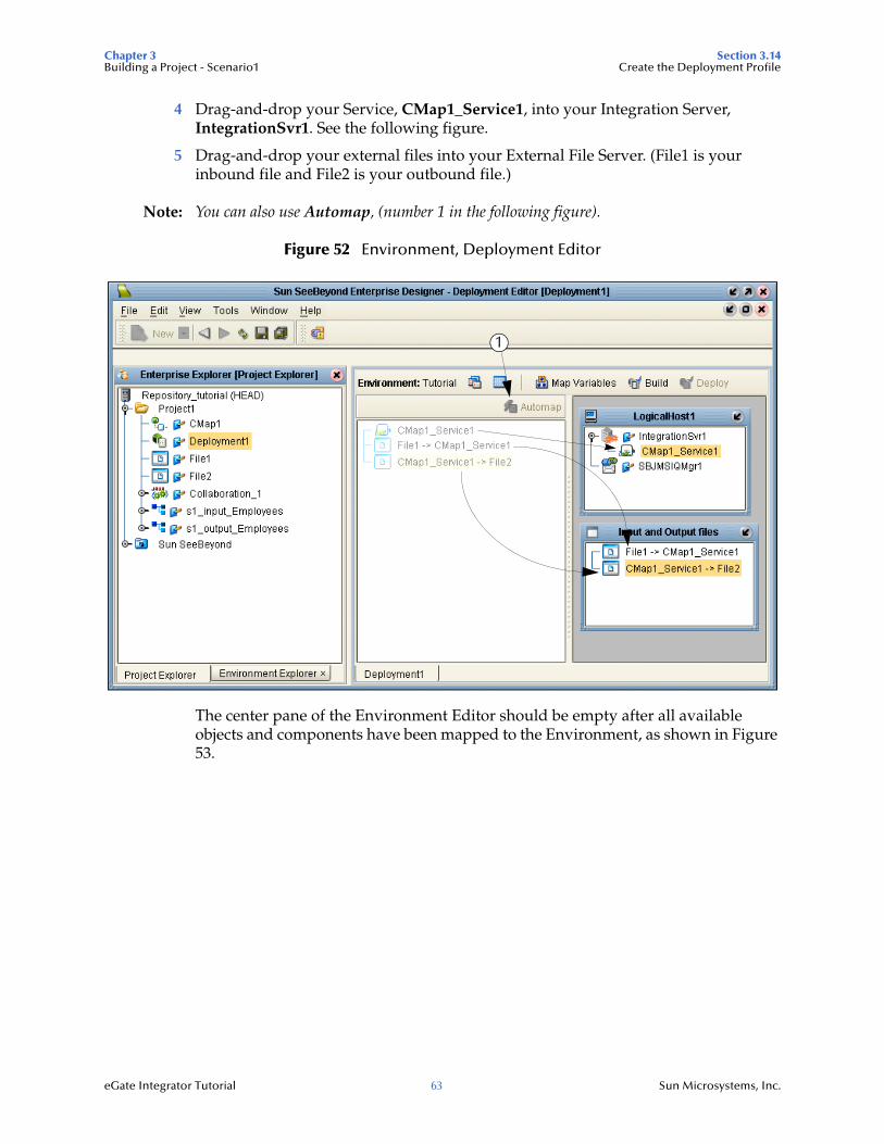
4 Drag-and-drop your Service, CMap1_Service1, into your Integration Server, IntegrationSvr1. See the following figure.
5 Drag-and-drop your external files into your External File Server. (File1 is your inbound file and File2 is your outbound file.)
Note: You can also use Automap, (number 1 in the following figure).
Figure 52 Environment, Deployment Editor
The center pane of the Environment Editor should be empty after all available objects and components have been mapped to the Environment, as shown in Figure 53.
1
Chapter 3 Section 3.15Building a Project - Scenario1 Build and Deploy the Project
eGate Integrator Tutorial 64 Sun Microsystems, Inc.
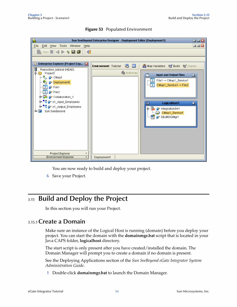
Figure 53 Populated Environment
You are now ready to build and deploy your project.
6 Save your Project.
3.15 Build and Deploy the ProjectIn this section you will run your Project.
3.15.1 Create a DomainMake sure an instance of the Logical Host is running (domain) before you deploy your project. You can start the domain with the domainmgr.bat script that is located in your Java CAPS folder, logicalhost directory.
The start script is only present after you have created/installed the domain. The Domain Manager will prompt you to create a domain if no domain is present.
See the Deploying Applications section of the Sun SeeBeyond eGate Integrator System Administration Guide.
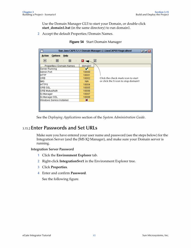
1 Double-click domainmgr.bat to launch the Domain Manager.
Chapter 3 Section 3.15Building a Project - Scenario1 Build and Deploy the Project
eGate Integrator Tutorial 65 Sun Microsystems, Inc.
Use the Domain Manager GUI to start your Domain, or double-click start_domain1.bat (in the same directory) to run domain1.
2 Accept the default Properties/Domain Names.
Figure 54 Start Domain Manager
See the Deploying Applications section of the System Administration Guide.
3.15.2 Enter Passwords and Set URLsMake sure you have entered your user name and password (see the steps below) for the Integration Server (and the JMS IQ Manager), and make sure your Domain server is running.
Integration Server Password
1 Click the Environment Explorer tab.
2 Right-click IntegrationSvr1 in the Environment Explorer tree.
3 Click Properties.
4 Enter and confirm Password.
See the following figure.
Click the check mark icon to startor click the X icon to stop domain1
Chapter 3 Section 3.15Building a Project - Scenario1 Build and Deploy the Project
eGate Integrator Tutorial 66 Sun Microsystems, Inc.
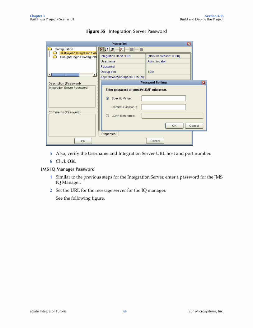
Figure 55 Integration Server Password
5 Also, verify the Username and Integration Server URL host and port number.
6 Click OK.
JMS IQ Manager Password
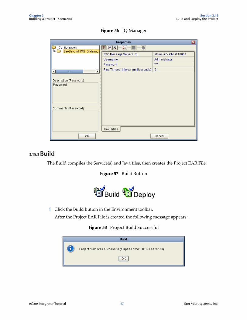
1 Similar to the previous steps for the Integration Server, enter a password for the JMS IQ Manager.
2 Set the URL for the message server for the IQ manager.
See the following figure.
Chapter 3 Section 3.15Building a Project - Scenario1 Build and Deploy the Project
eGate Integrator Tutorial 67 Sun Microsystems, Inc.
Figure 56 IQ Manager
3.15.3 BuildThe Build compiles the Service(s) and Java files, then creates the Project EAR File.
Figure 57 Build Button
1 Click the Build button in the Environment toolbar.
After the Project EAR File is created the following message appears:
Figure 58 Project Build Successful
Chapter 3 Section 3.16Building a Project - Scenario1 Verify the Output Data
eGate Integrator Tutorial 68 Sun Microsystems, Inc.
3.15.4 DeployIn this section, deploy your Project to start the Integration Server and start the deployment.
Note: Before you can deploy your Project, an instance of the Logical Host (domain) must be running.
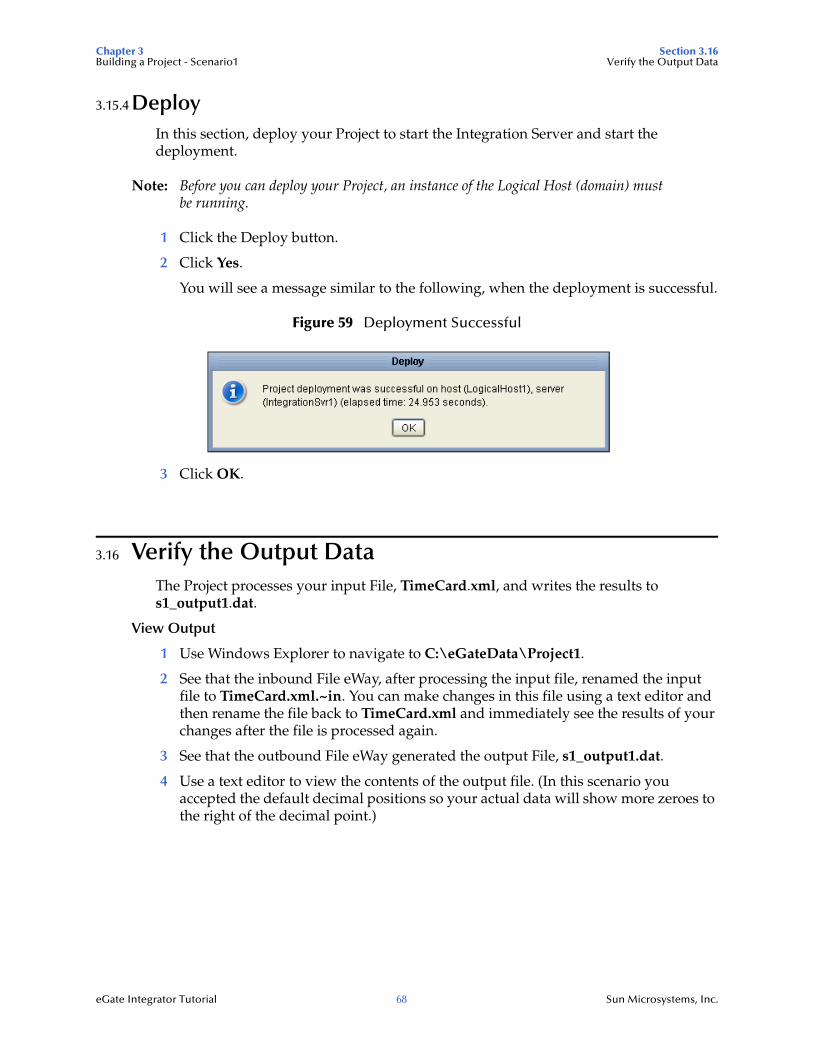
1 Click the Deploy button.
2 Click Yes.
You will see a message similar to the following, when the deployment is successful.
Figure 59 Deployment Successful
3 Click OK.
3.16 Verify the Output DataThe Project processes your input File, TimeCard.xml, and writes the results to s1_output1.dat.
View Output
1 Use Windows Explorer to navigate to C:\eGateData\Project1.
2 See that the inbound File eWay, after processing the input file, renamed the input file to TimeCard.xml.~in. You can make changes in this file using a text editor and then rename the file back to TimeCard.xml and immediately see the results of your changes after the file is processed again.
3 See that the outbound File eWay generated the output File, s1_output1.dat.
4 Use a text editor to view the contents of the output file. (In this scenario you accepted the default decimal positions so your actual data will show more zeroes to the right of the decimal point.)
Chapter 3 Section 3.16Building a Project - Scenario1 Verify the Output Data
eGate Integrator Tutorial 69 Sun Microsystems, Inc.
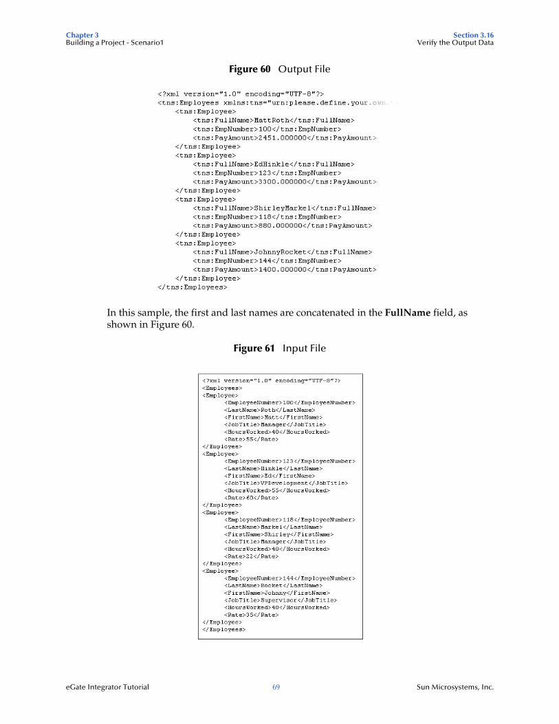
Figure 60 Output File
In this sample, the first and last names are concatenated in the FullName field, as shown in Figure 60.
Figure 61 Input File
Chapter 3 Section 3.16Building a Project - Scenario1 Verify the Output Data
eGate Integrator Tutorial 70 Sun Microsystems, Inc.
3.16.1 Text EditorWith your Integration server running, you may edit the input, TimeCard, File in real time and change the data names or values in that file.
You can edit the input file using a text edit application such as WordPad. As a test you can change one or two names in the file.
After your input data is processed, the file name is changed to TimeCard.xml.~in. When you delete the file extension name .~in, the TimeCard.xml File is processed again.
Note: If the “.~in” does not appear in your folder view you may need to change the Windows setting under “Folder Options.” Go to the View tab and uncheck “Hide extensions for known file types.”
Within a few seconds after deleting the extension ~in, the File eWay processes the input file again and writes the results to s1_output.dat. If your Multiple Records per file setting is “False,” a new output file will be created each time the input data is processed. Open the output file with a text edit program and view the data to see your changes.
eGate Integrator Tutorial 71 Sun Microsystems, Inc.
Chapter 4
Building a Project - Scenario2
This Tutorial provides step-by-step procedures for creating and testing an eGate Project, using sample data. Project2 demonstrates how to use an input payroll File containing hours worked and rate to calculate gross pay and then output a payroll File with gross pay data.
What’s in This Chapter
Business Challenge on page 71
Project Overview on page 72
Sample Data for Project2 on page 74
Create a New Project on page 75
Create a New Object Type Definition on page 78
Configure a Service for Input on page 86
Apply Business Rules on page 91
Configure a Service for Output on page 93
Apply Business Rules for jcd_Payroll_out on page 99
Create a Connectivity Map on page 104
Add Objects to the Connectivity Map on page 106
Configure eWays and JMS Connections on page 111
Create an Environment on page 115
Create and Activate the Deployment Profile on page 120
Build and Deploy the Project on page 122
Verify Output Data on page 123
4.1 Business ChallengeThe Project described in this chapter provides a solution to the following business challenge:
Chapter 4 Section 4.2Building a Project - Scenario2 Project Overview
eGate Integrator Tutorial 72 Sun Microsystems, Inc.
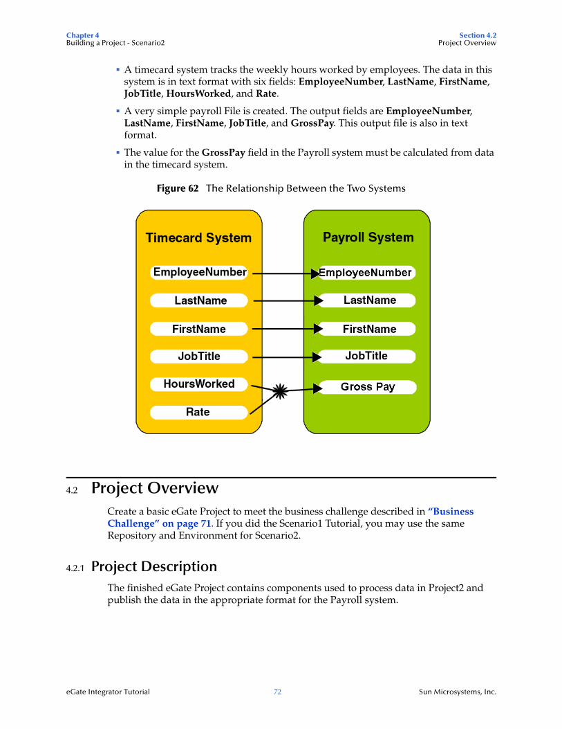
A timecard system tracks the weekly hours worked by employees. The data in this system is in text format with six fields: EmployeeNumber, LastName, FirstName, JobTitle, HoursWorked, and Rate.
A very simple payroll File is created. The output fields are EmployeeNumber, LastName, FirstName, JobTitle, and GrossPay. This output file is also in text format.
The value for the GrossPay field in the Payroll system must be calculated from data in the timecard system.
Figure 62 The Relationship Between the Two Systems
4.2 Project OverviewCreate a basic eGate Project to meet the business challenge described in “Business Challenge” on page 71. If you did the Scenario1 Tutorial, you may use the same Repository and Environment for Scenario2.
4.2.1 Project DescriptionThe finished eGate Project contains components used to process data in Project2 and publish the data in the appropriate format for the Payroll system.
Chapter 4 Section 4.2Building a Project - Scenario2 Project Overview
eGate Integrator Tutorial 73 Sun Microsystems, Inc.
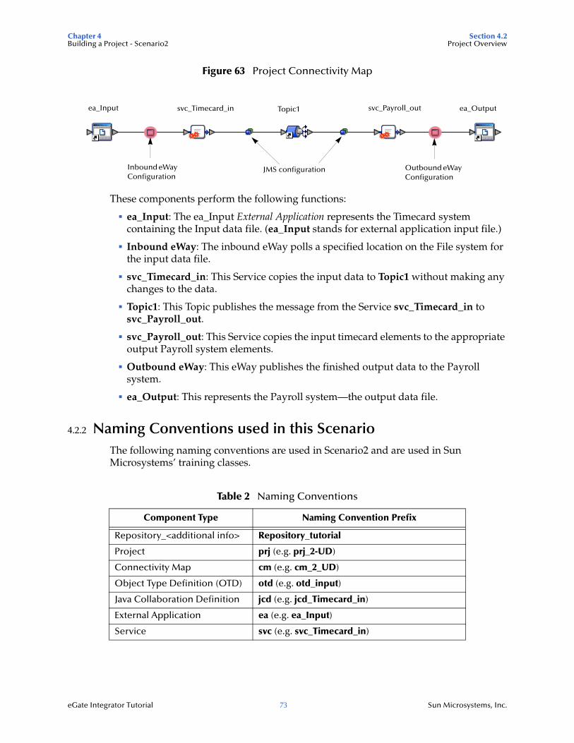
Figure 63 Project Connectivity Map
These components perform the following functions:
ea_Input: The ea_Input External Application represents the Timecard system containing the Input data file. (ea_Input stands for external application input file.)
Inbound eWay: The inbound eWay polls a specified location on the File system for the input data file.
svc_Timecard_in: This Service copies the input data to Topic1 without making any changes to the data.
Topic1: This Topic publishes the message from the Service svc_Timecard_in to svc_Payroll_out.
svc_Payroll_out: This Service copies the input timecard elements to the appropriate output Payroll system elements.
Outbound eWay: This eWay publishes the finished output data to the Payroll system.
ea_Output: This represents the Payroll system—the output data file.
4.2.2 Naming Conventions used in this ScenarioThe following naming conventions are used in Scenario2 and are used in Sun Microsystems’ training classes.
Table 2 Naming Conventions
Component Type Naming Convention Prefix
Repository_<additional info> Repository_tutorial
Project prj (e.g. prj_2-UD)
Connectivity Map cm (e.g. cm_2_UD)
Object Type Definition (OTD) otd (e.g. otd_input)
Java Collaboration Definition jcd (e.g. jcd_Timecard_in)
External Application ea (e.g. ea_Input)
Service svc (e.g. svc_Timecard_in)
Inbound eWay Configuration
Outbound eWay Configuration
JMS configuration
ea_Input svc_Timecard_in Topic1 svc_Payroll_out ea_Output
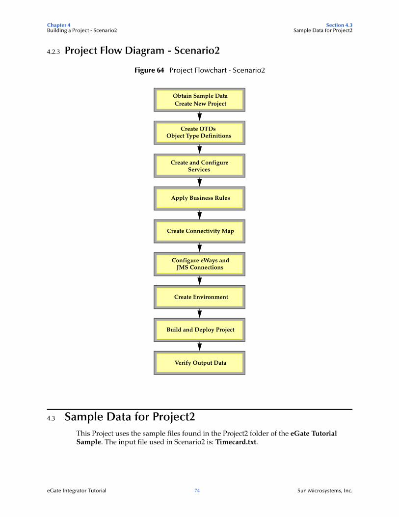
Chapter 4 Section 4.3Building a Project - Scenario2 Sample Data for Project2
eGate Integrator Tutorial 74 Sun Microsystems, Inc.
4.2.3 Project Flow Diagram - Scenario2
Figure 64 Project Flowchart - Scenario2
4.3 Sample Data for Project2This Project uses the sample files found in the Project2 folder of the eGate Tutorial Sample. The input file used in Scenario2 is: Timecard.txt.
Obtain Sample DataCreate New Project
Create OTDsObject Type Definitions
Apply Business Rules
Create Connectivity Map
Configure eWays andJMS Connections
Create Environment
Build and Deploy Project
Verify Output Data
Create and ConfigureServices
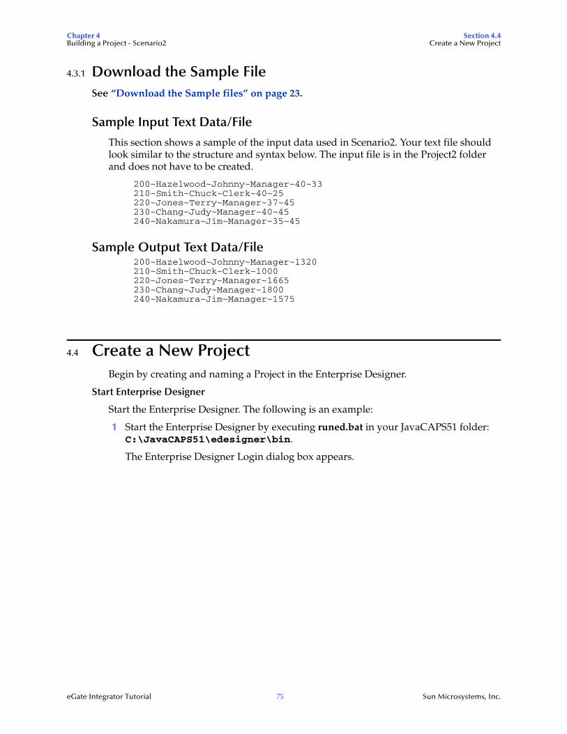
Chapter 4 Section 4.4Building a Project - Scenario2 Create a New Project
eGate Integrator Tutorial 75 Sun Microsystems, Inc.
4.3.1 Download the Sample FileSee “Download the Sample files” on page 23.
Sample Input Text Data/File
This section shows a sample of the input data used in Scenario2. Your text file should look similar to the structure and syntax below. The input file is in the Project2 folder and does not have to be created.
200~Hazelwood~Johnny~Manager~40~33210~Smith~Chuck~Clerk~40~25220~Jones~Terry~Manager~37~45230~Chang~Judy~Manager~40~45240~Nakamura~Jim~Manager~35~45
Sample Output Text Data/File200~Hazelwood~Johnny~Manager~1320210~Smith~Chuck~Clerk~1000220~Jones~Terry~Manager~1665230~Chang~Judy~Manager~1800240~Nakamura~Jim~Manager~1575
4.4 Create a New ProjectBegin by creating and naming a Project in the Enterprise Designer.
Start Enterprise Designer
Start the Enterprise Designer. The following is an example:
1 Start the Enterprise Designer by executing runed.bat in your JavaCAPS51 folder: C:\JavaCAPS51\edesigner\bin.
The Enterprise Designer Login dialog box appears.
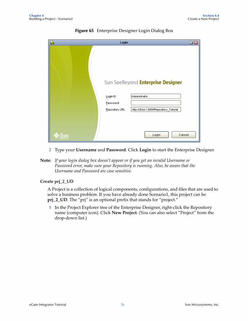
Chapter 4 Section 4.4Building a Project - Scenario2 Create a New Project
eGate Integrator Tutorial 76 Sun Microsystems, Inc.
Figure 65 Enterprise Designer Login Dialog Box
2 Type your Username and Password. Click Login to start the Enterprise Designer.
Note: If your login dialog box doesn’t appear or if you get an invalid Username or Password error, make sure your Repository is running. Also, be aware that the Username and Password are case sensitive.
Create prj_2_UD
A Project is a collection of logical components, configurations, and files that are used to solve a business problem. If you have already done Scenario1, this project can be prj_2_UD. The “prj” is an optional prefix that stands for “project.”
1 In the Project Explorer tree of the Enterprise Designer, right-click the Repository name (computer icon). Click New Project. (You can also select “Project” from the drop-down list.)
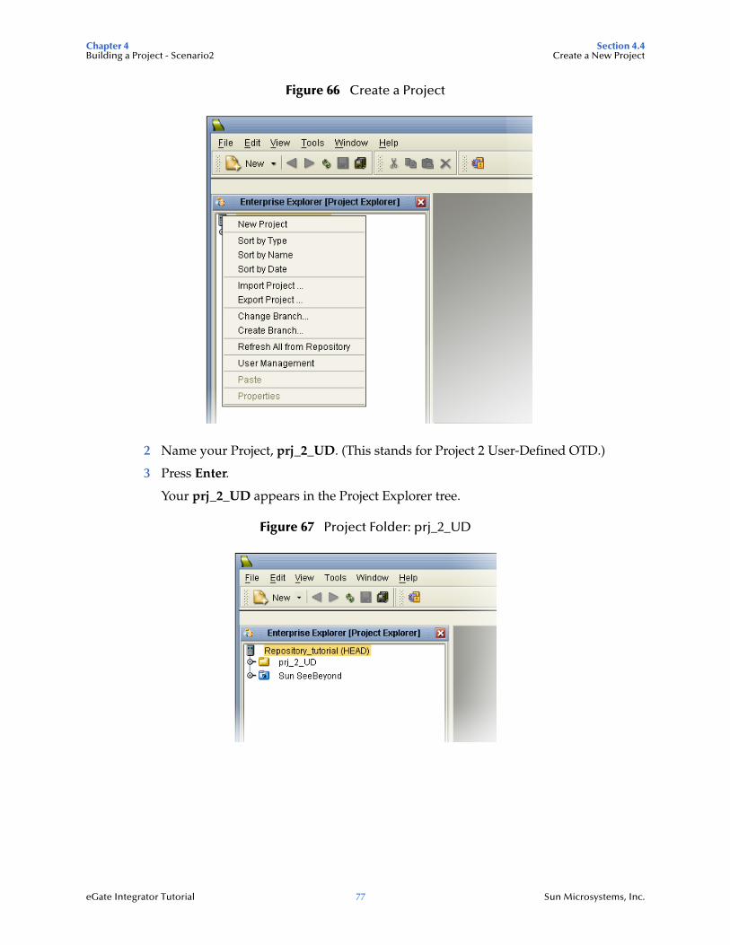
Chapter 4 Section 4.4Building a Project - Scenario2 Create a New Project
eGate Integrator Tutorial 77 Sun Microsystems, Inc.
Figure 66 Create a Project
2 Name your Project, prj_2_UD. (This stands for Project 2 User-Defined OTD.)
3 Press Enter.
Your prj_2_UD appears in the Project Explorer tree.
Figure 67 Project Folder: prj_2_UD
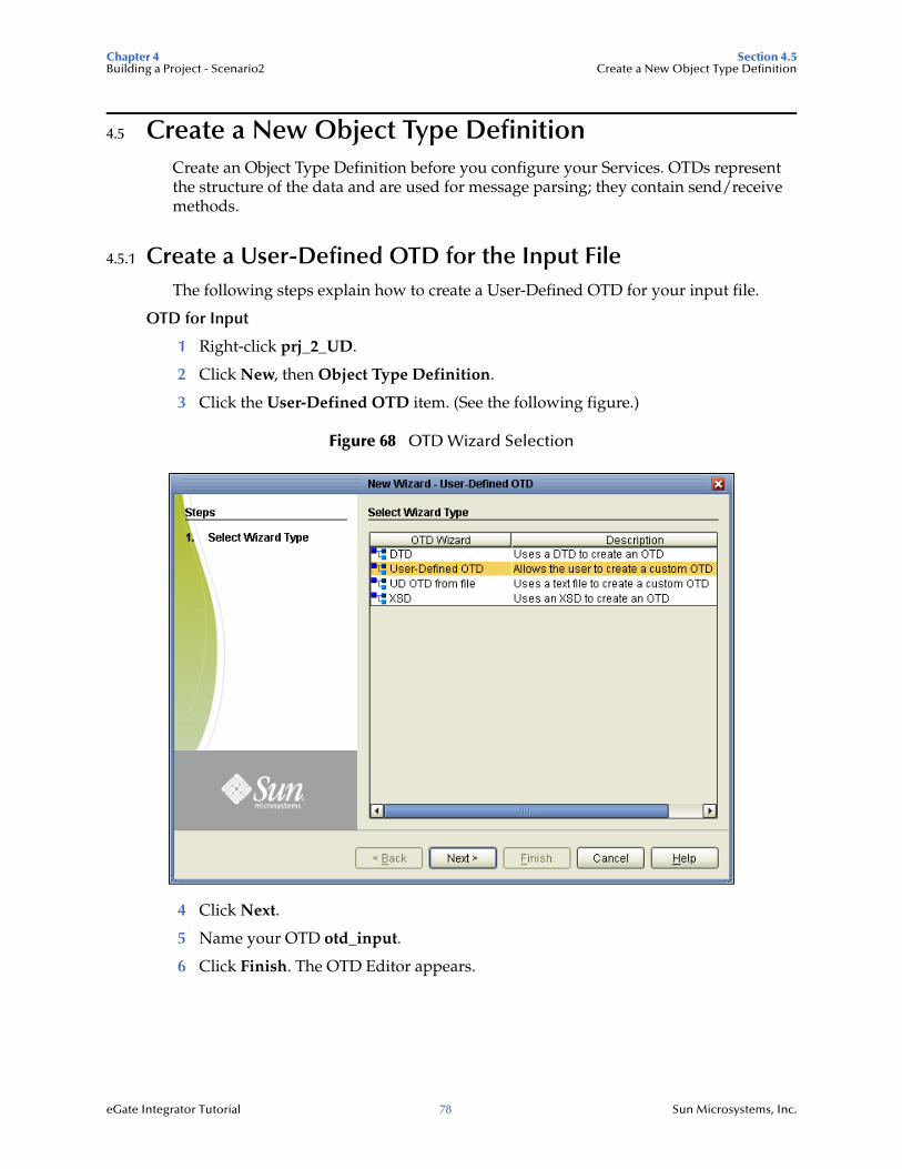
Chapter 4 Section 4.5Building a Project - Scenario2 Create a New Object Type Definition
eGate Integrator Tutorial 78 Sun Microsystems, Inc.
4.5 Create a New Object Type DefinitionCreate an Object Type Definition before you configure your Services. OTDs represent the structure of the data and are used for message parsing; they contain send/receive methods.
4.5.1 Create a User-Defined OTD for the Input FileThe following steps explain how to create a User-Defined OTD for your input file.
OTD for Input
1 Right-click prj_2_UD.
2 Click New, then Object Type Definition.
3 Click the User-Defined OTD item. (See the following figure.)
Figure 68 OTD Wizard Selection
4 Click Next.
5 Name your OTD otd_input.
6 Click Finish. The OTD Editor appears.
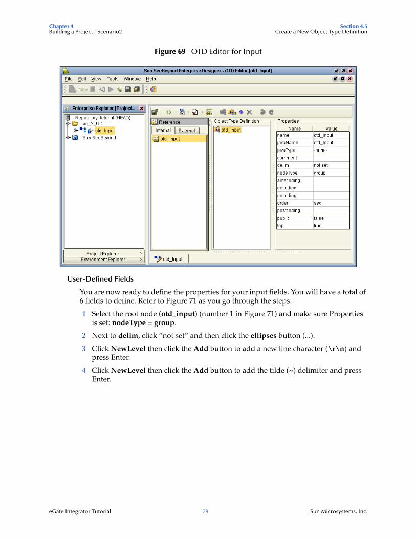
Chapter 4 Section 4.5Building a Project - Scenario2 Create a New Object Type Definition
eGate Integrator Tutorial 79 Sun Microsystems, Inc.
Figure 69 OTD Editor for Input
User-Defined Fields
You are now ready to define the properties for your input fields. You will have a total of 6 fields to define. Refer to Figure 71 as you go through the steps.
1 Select the root node (otd_input) (number 1 in Figure 71) and make sure Properties is set: nodeType = group.
2 Next to delim, click “not set” and then click the ellipses button (...).
3 Click NewLevel then click the Add button to add a new line character (\r\n) and press Enter.
4 Click NewLevel then click the Add button to add the tilde (~) delimiter and press Enter.
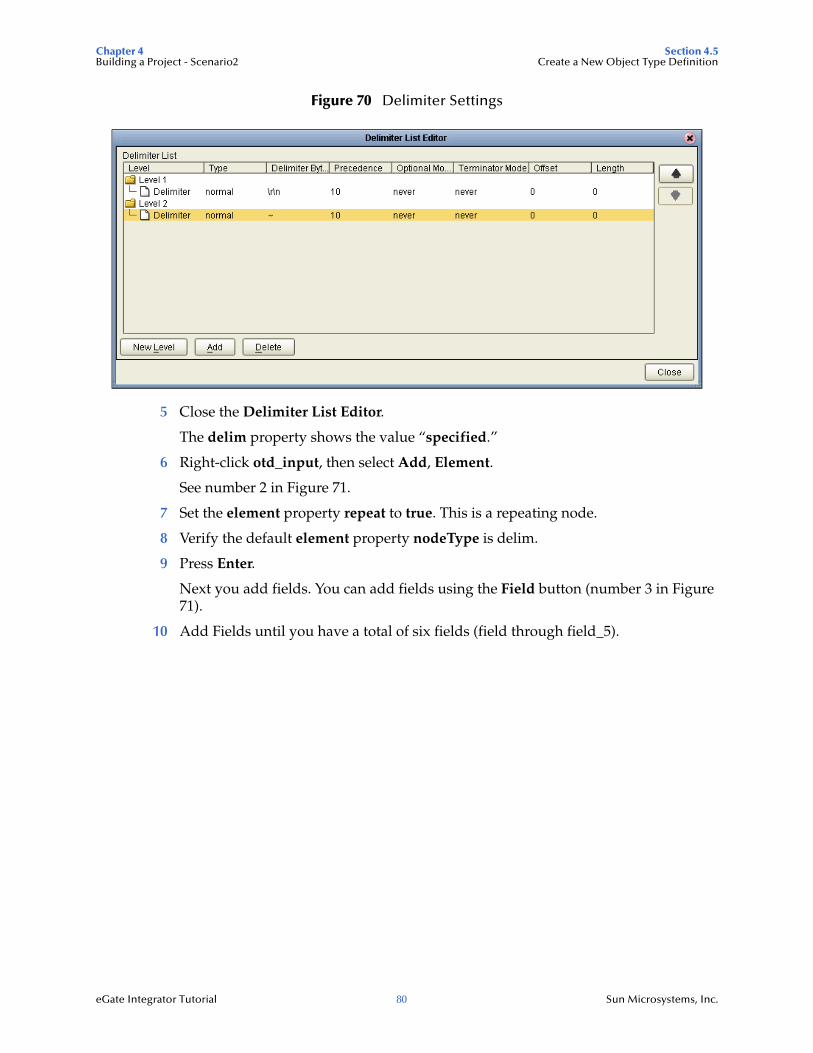
Chapter 4 Section 4.5Building a Project - Scenario2 Create a New Object Type Definition
eGate Integrator Tutorial 80 Sun Microsystems, Inc.
Figure 70 Delimiter Settings
5 Close the Delimiter List Editor.
The delim property shows the value “specified.”
6 Right-click otd_input, then select Add, Element.
See number 2 in Figure 71.
7 Set the element property repeat to true. This is a repeating node.
8 Verify the default element property nodeType is delim.
9 Press Enter.
Next you add fields. You can add fields using the Field button (number 3 in Figure 71).
10 Add Fields until you have a total of six fields (field through field_5).
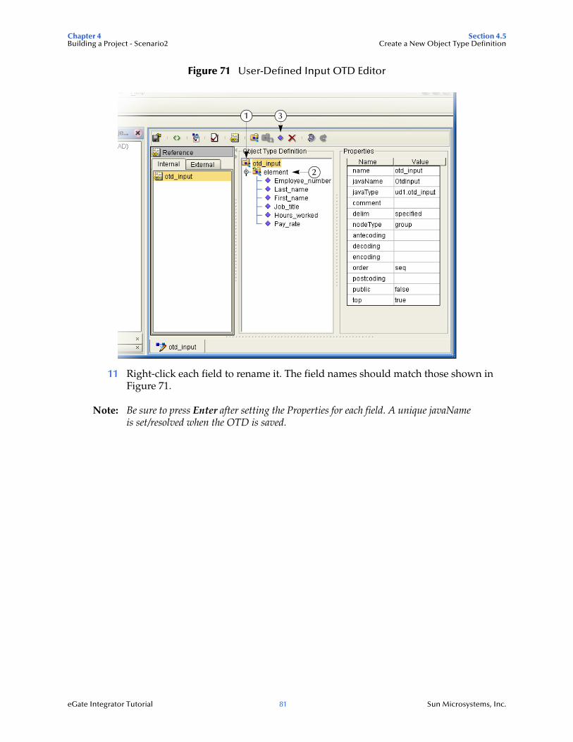
Chapter 4 Section 4.5Building a Project - Scenario2 Create a New Object Type Definition
eGate Integrator Tutorial 81 Sun Microsystems, Inc.
Figure 71 User-Defined Input OTD Editor
11 Right-click each field to rename it. The field names should match those shown in Figure 71.
Note: Be sure to press Enter after setting the Properties for each field. A unique javaName is set/resolved when the OTD is saved.
1
2
3
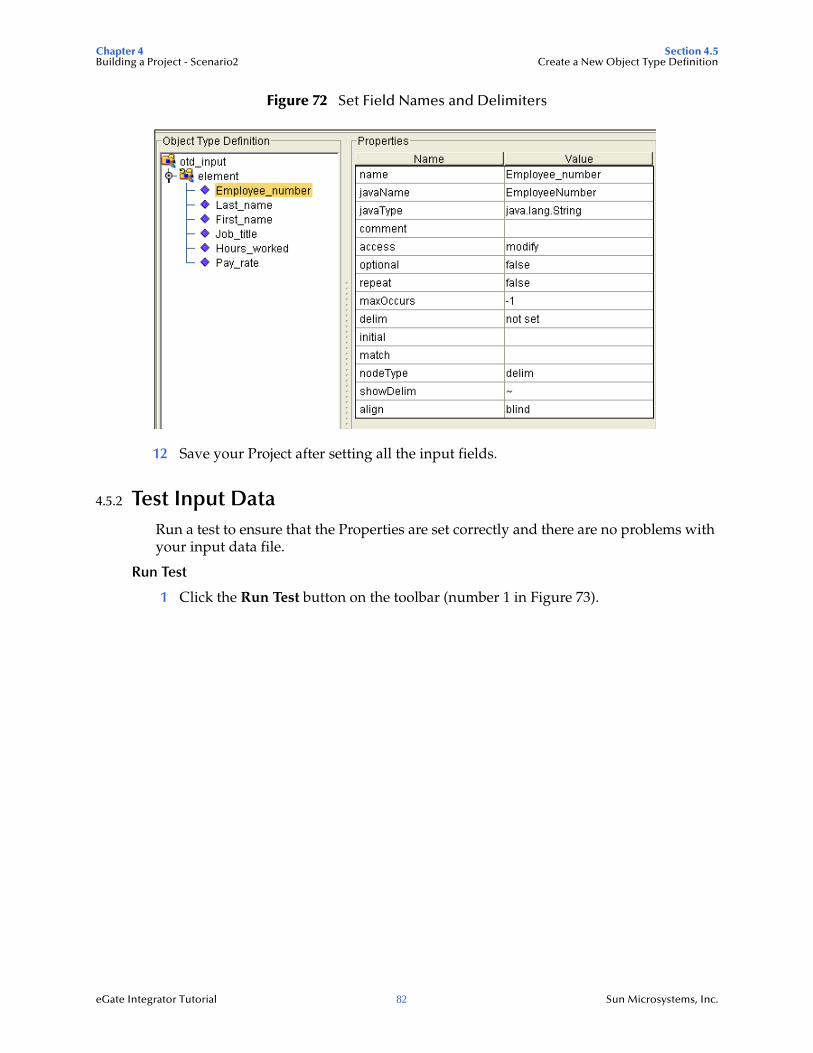
Chapter 4 Section 4.5Building a Project - Scenario2 Create a New Object Type Definition
eGate Integrator Tutorial 82 Sun Microsystems, Inc.
Figure 72 Set Field Names and Delimiters
12 Save your Project after setting all the input fields.
4.5.2 Test Input DataRun a test to ensure that the Properties are set correctly and there are no problems with your input data file.
Run Test
1 Click the Run Test button on the toolbar (number 1 in Figure 73).
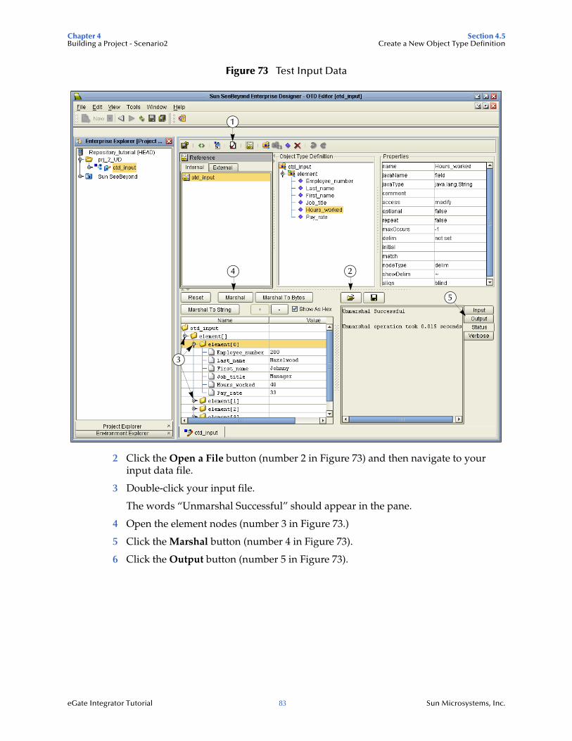
Chapter 4 Section 4.5Building a Project - Scenario2 Create a New Object Type Definition
eGate Integrator Tutorial 83 Sun Microsystems, Inc.
Figure 73 Test Input Data
2 Click the Open a File button (number 2 in Figure 73) and then navigate to your input data file.
3 Double-click your input file.
The words “Unmarshal Successful” should appear in the pane.
4 Open the element nodes (number 3 in Figure 73.)
5 Click the Marshal button (number 4 in Figure 73).
6 Click the Output button (number 5 in Figure 73).
1
2
3
4
5
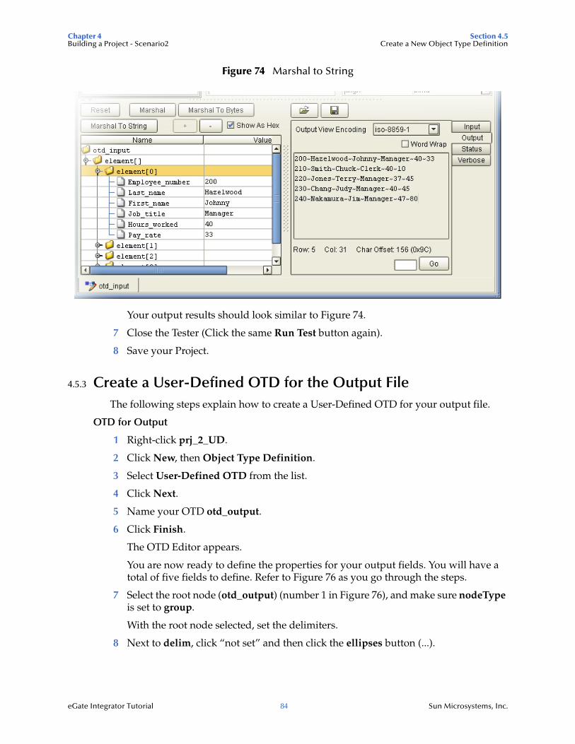
Chapter 4 Section 4.5Building a Project - Scenario2 Create a New Object Type Definition
eGate Integrator Tutorial 84 Sun Microsystems, Inc.
Figure 74 Marshal to String
Your output results should look similar to Figure 74.
7 Close the Tester (Click the same Run Test button again).
8 Save your Project.
4.5.3 Create a User-Defined OTD for the Output FileThe following steps explain how to create a User-Defined OTD for your output file.
OTD for Output
1 Right-click prj_2_UD.
2 Click New, then Object Type Definition.
3 Select User-Defined OTD from the list.
4 Click Next.
5 Name your OTD otd_output.
6 Click Finish.
The OTD Editor appears.
You are now ready to define the properties for your output fields. You will have a total of five fields to define. Refer to Figure 76 as you go through the steps.
7 Select the root node (otd_output) (number 1 in Figure 76), and make sure nodeType is set to group.
With the root node selected, set the delimiters.
8 Next to delim, click “not set” and then click the ellipses button (...).
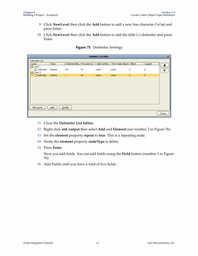
Chapter 4 Section 4.5Building a Project - Scenario2 Create a New Object Type Definition
eGate Integrator Tutorial 85 Sun Microsystems, Inc.
9 Click NewLevel then click the Add button to add a new line character (\r\n) and press Enter.
10 Click NewLevel then click the Add button to add the tilde (~) delimiter and press Enter.
Figure 75 Delimiter Settings
11 Close the Delimiter List Editor.
12 Right-click otd_output then select Add and Element (see number 2 in Figure 76).
13 Set the element property repeat to true. This is a repeating node.
14 Verify the element property nodeType is delim.
15 Press Enter.
Next you add fields. You can add fields using the Field button (number 3 in Figure 76).
16 Add Fields until you have a total of five fields.
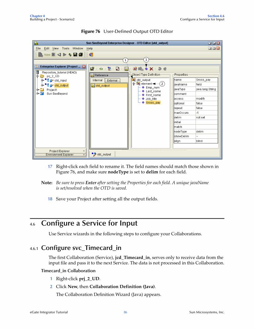
Chapter 4 Section 4.6Building a Project - Scenario2 Configure a Service for Input
eGate Integrator Tutorial 86 Sun Microsystems, Inc.
Figure 76 User-Defined Output OTD Editor
17 Right-click each field to rename it. The field names should match those shown in Figure 76, and make sure nodeType is set to delim for each field.
Note: Be sure to press Enter after setting the Properties for each field. A unique javaName is set/resolved when the OTD is saved.
18 Save your Project after setting all the output fields.
4.6 Configure a Service for InputUse Service wizards in the following steps to configure your Collaborations.
4.6.1 Configure svc_Timecard_inThe first Collaboration (Service), jcd_Timecard_in, serves only to receive data from the input file and pass it to the next Service. The data is not processed in this Collaboration.
Timecard_in Collaboration
1 Right-click prj_2_UD.
2 Click New, then Collaboration Definition (Java).
The Collaboration Definition Wizard (Java) appears.
1
2
3
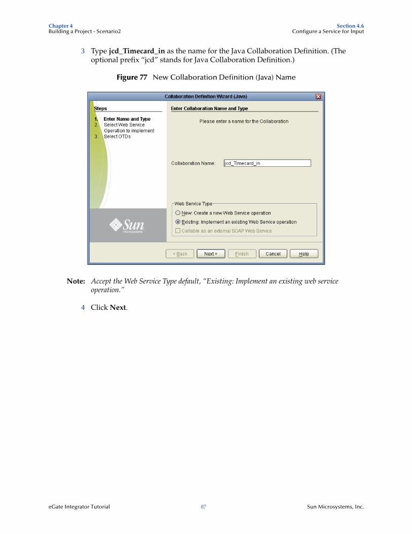
Chapter 4 Section 4.6Building a Project - Scenario2 Configure a Service for Input
eGate Integrator Tutorial 87 Sun Microsystems, Inc.
3 Type jcd_Timecard_in as the name for the Java Collaboration Definition. (The optional prefix “jcd” stands for Java Collaboration Definition.)
Figure 77 New Collaboration Definition (Java) Name
Note: Accept the Web Service Type default, “Existing: Implement an existing web service operation.”
4 Click Next.
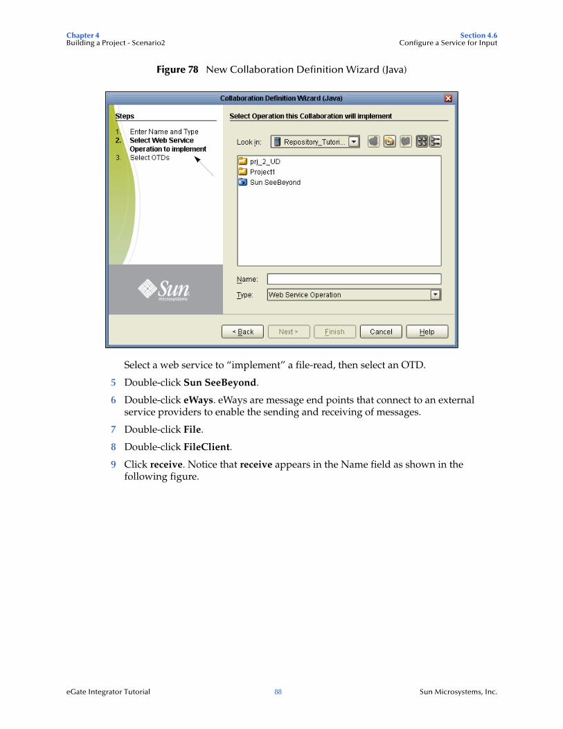
Chapter 4 Section 4.6Building a Project - Scenario2 Configure a Service for Input
eGate Integrator Tutorial 88 Sun Microsystems, Inc.
Figure 78 New Collaboration Definition Wizard (Java)
Select a web service to “implement” a file-read, then select an OTD.
5 Double-click Sun SeeBeyond.
6 Double-click eWays. eWays are message end points that connect to an external service providers to enable the sending and receiving of messages.
7 Double-click File.
8 Double-click FileClient.
9 Click receive. Notice that receive appears in the Name field as shown in the following figure.
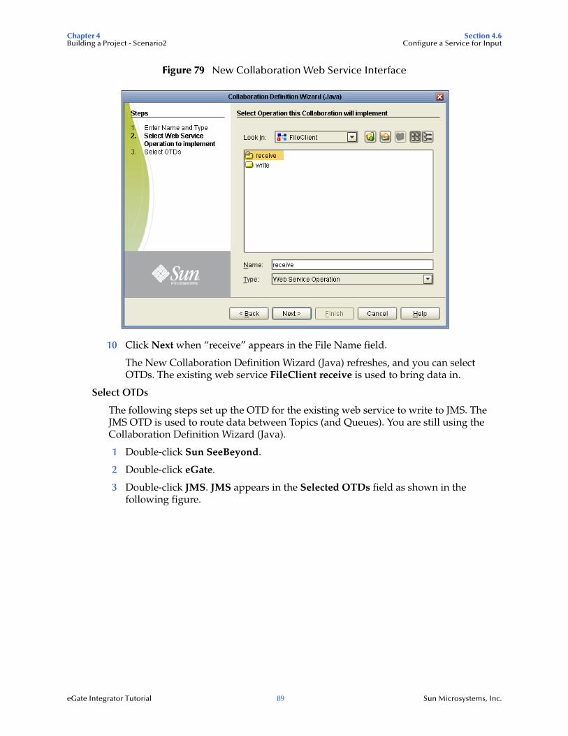
Chapter 4 Section 4.6Building a Project - Scenario2 Configure a Service for Input
eGate Integrator Tutorial 89 Sun Microsystems, Inc.
Figure 79 New Collaboration Web Service Interface
10 Click Next when “receive” appears in the File Name field.
The New Collaboration Definition Wizard (Java) refreshes, and you can select OTDs. The existing web service FileClient receive is used to bring data in.
Select OTDs
The following steps set up the OTD for the existing web service to write to JMS. The JMS OTD is used to route data between Topics (and Queues). You are still using the Collaboration Definition Wizard (Java).
1 Double-click Sun SeeBeyond.
2 Double-click eGate.
3 Double-click JMS. JMS appears in the Selected OTDs field as shown in the following figure.
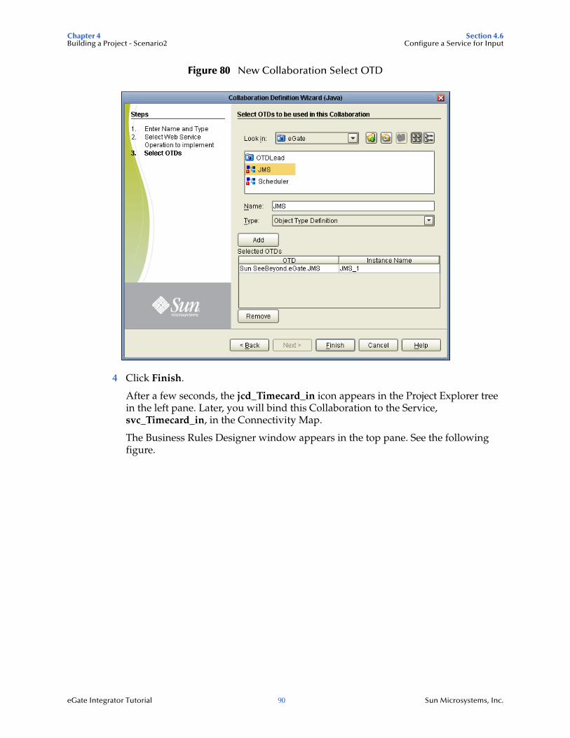
Chapter 4 Section 4.6Building a Project - Scenario2 Configure a Service for Input
eGate Integrator Tutorial 90 Sun Microsystems, Inc.
Figure 80 New Collaboration Select OTD
4 Click Finish.
After a few seconds, the jcd_Timecard_in icon appears in the Project Explorer tree in the left pane. Later, you will bind this Collaboration to the Service, svc_Timecard_in, in the Connectivity Map.
The Business Rules Designer window appears in the top pane. See the following figure.
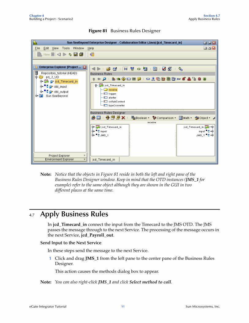
Chapter 4 Section 4.7Building a Project - Scenario2 Apply Business Rules
eGate Integrator Tutorial 91 Sun Microsystems, Inc.
Figure 81 Business Rules Designer
Note: Notice that the objects in Figure 81 reside in both the left and right pane of the Business Rules Designer window. Keep in mind that the OTD instances (JMS_1 for example) refer to the same object although they are shown in the GUI in two different places at the same time.
4.7 Apply Business RulesIn jcd_Timecard_in connect the input from the Timecard to the JMS OTD. The JMS passes the message through to the next Service. The processing of the message occurs in the next Service, jcd_Payroll_out.
Send Input to the Next Service
In these steps send the message to the next Service.
1 Click and drag JMS_1 from the left pane to the center pane of the Business Rules Designer.
This action causes the methods dialog box to appear.
Note: You can also right-click JMS_1 and click Select method to call.
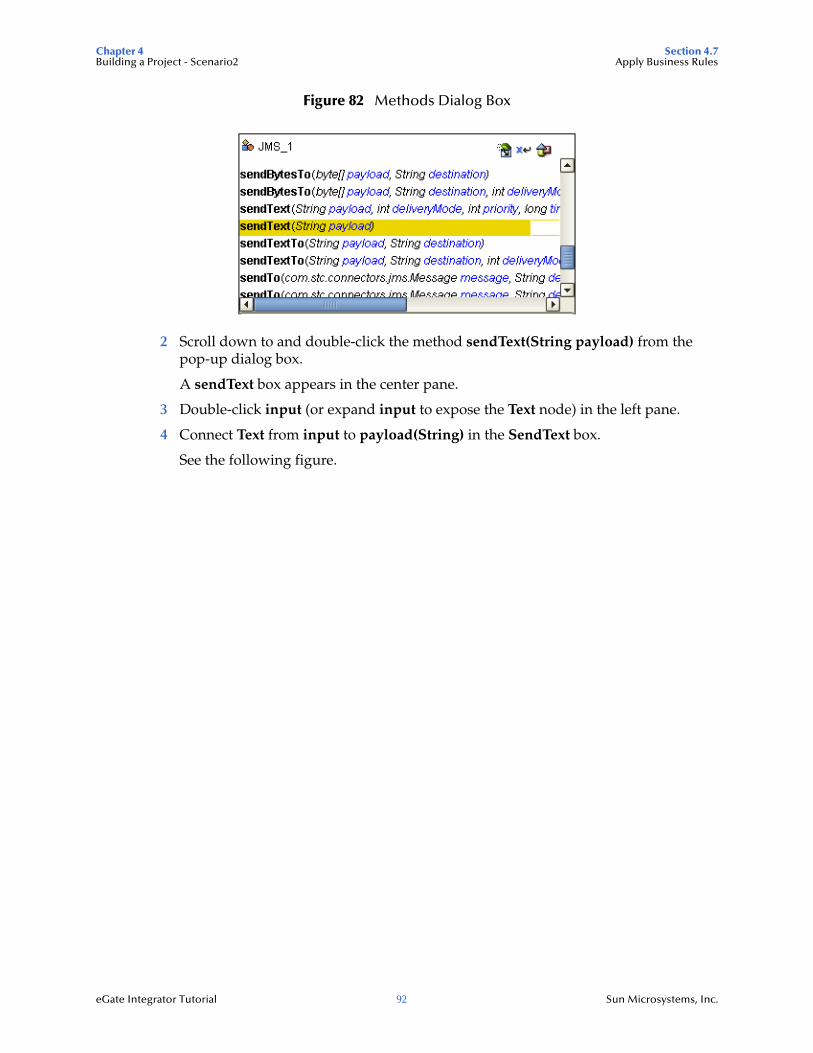
Chapter 4 Section 4.7Building a Project - Scenario2 Apply Business Rules
eGate Integrator Tutorial 92 Sun Microsystems, Inc.
Figure 82 Methods Dialog Box
2 Scroll down to and double-click the method sendText(String payload) from the pop-up dialog box.
A sendText box appears in the center pane.
3 Double-click input (or expand input to expose the Text node) in the left pane.
4 Connect Text from input to payload(String) in the SendText box.
See the following figure.
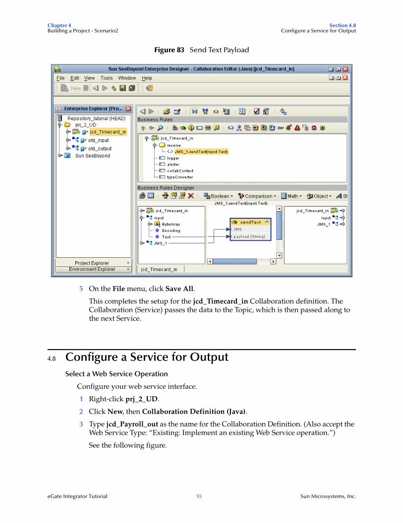
Chapter 4 Section 4.8Building a Project - Scenario2 Configure a Service for Output
eGate Integrator Tutorial 93 Sun Microsystems, Inc.
Figure 83 Send Text Payload
5 On the File menu, click Save All.
This completes the setup for the jcd_Timecard_in Collaboration definition. The Collaboration (Service) passes the data to the Topic, which is then passed along to the next Service.
4.8 Configure a Service for OutputSelect a Web Service Operation
Configure your web service interface.
1 Right-click prj_2_UD.
2 Click New, then Collaboration Definition (Java).
3 Type jcd_Payroll_out as the name for the Collaboration Definition. (Also accept the Web Service Type: “Existing: Implement an existing Web Service operation.”)
See the following figure.
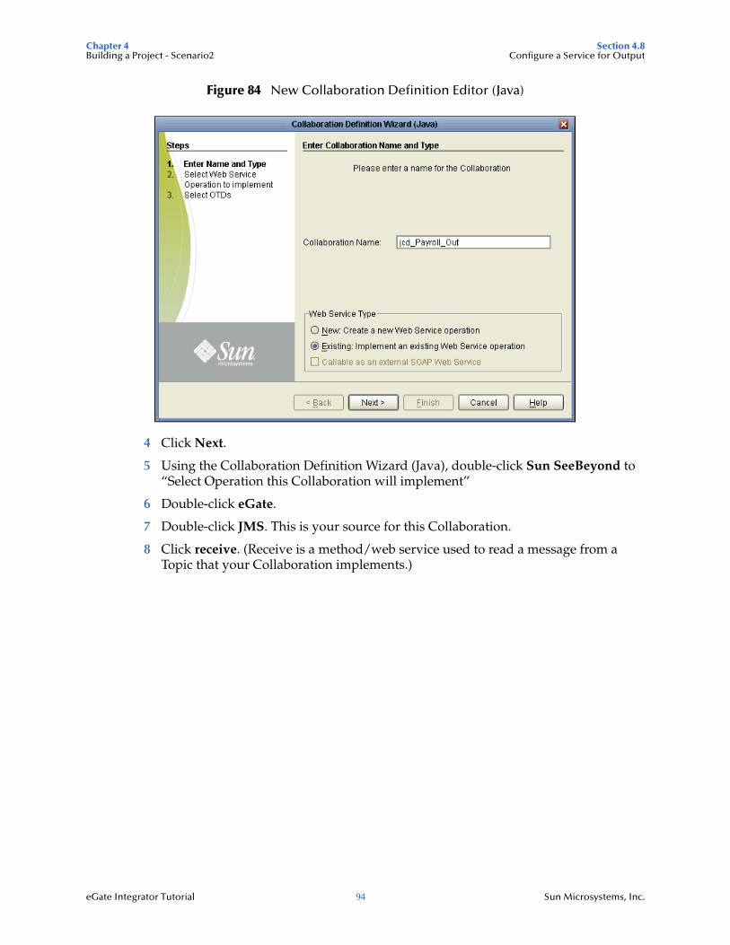
Chapter 4 Section 4.8Building a Project - Scenario2 Configure a Service for Output
eGate Integrator Tutorial 94 Sun Microsystems, Inc.
Figure 84 New Collaboration Definition Editor (Java)
4 Click Next.
5 Using the Collaboration Definition Wizard (Java), double-click Sun SeeBeyond to “Select Operation this Collaboration will implement”
6 Double-click eGate.
7 Double-click JMS. This is your source for this Collaboration.
8 Click receive. (Receive is a method/web service used to read a message from a Topic that your Collaboration implements.)
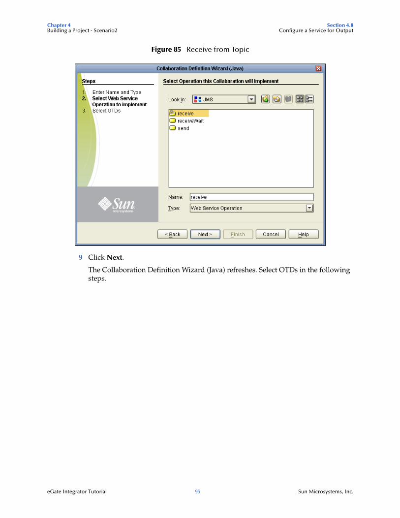
Chapter 4 Section 4.8Building a Project - Scenario2 Configure a Service for Output
eGate Integrator Tutorial 95 Sun Microsystems, Inc.
Figure 85 Receive from Topic
9 Click Next.
The Collaboration Definition Wizard (Java) refreshes. Select OTDs in the following steps.
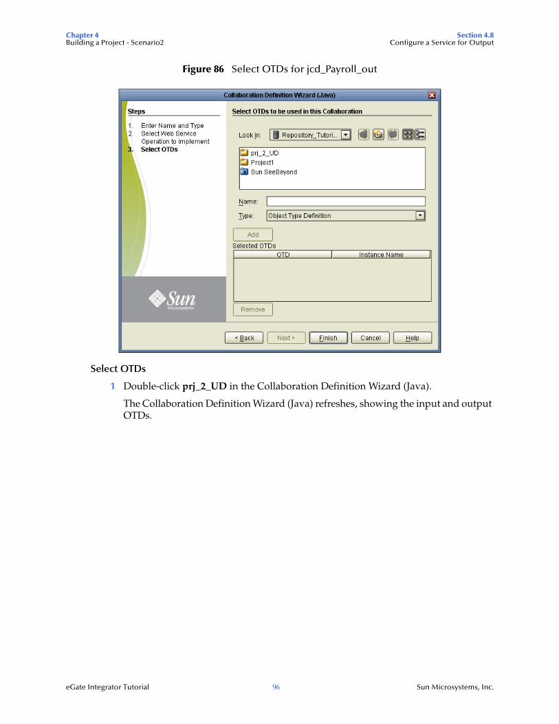
Chapter 4 Section 4.8Building a Project - Scenario2 Configure a Service for Output
eGate Integrator Tutorial 96 Sun Microsystems, Inc.
Figure 86 Select OTDs for jcd_Payroll_out
Select OTDs
1 Double-click prj_2_UD in the Collaboration Definition Wizard (Java).
The Collaboration Definition Wizard (Java) refreshes, showing the input and output OTDs.
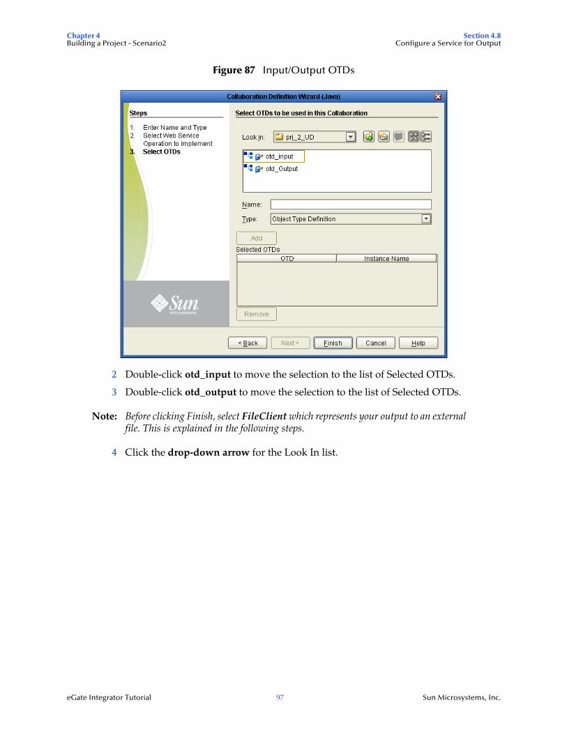
Chapter 4 Section 4.8Building a Project - Scenario2 Configure a Service for Output
eGate Integrator Tutorial 97 Sun Microsystems, Inc.
Figure 87 Input/Output OTDs
2 Double-click otd_input to move the selection to the list of Selected OTDs.
3 Double-click otd_output to move the selection to the list of Selected OTDs.
Note: Before clicking Finish, select FileClient which represents your output to an external file. This is explained in the following steps.
4 Click the drop-down arrow for the Look In list.
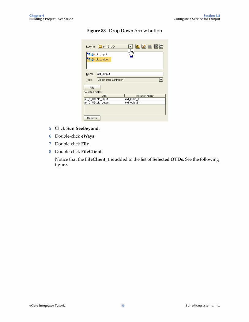
Chapter 4 Section 4.8Building a Project - Scenario2 Configure a Service for Output
eGate Integrator Tutorial 98 Sun Microsystems, Inc.
Figure 88 Drop Down Arrow button
5 Click Sun SeeBeyond.
6 Double-click eWays.
7 Double-click File.
8 Double-click FileClient.
Notice that the FileClient_1 is added to the list of Selected OTDs. See the following figure.
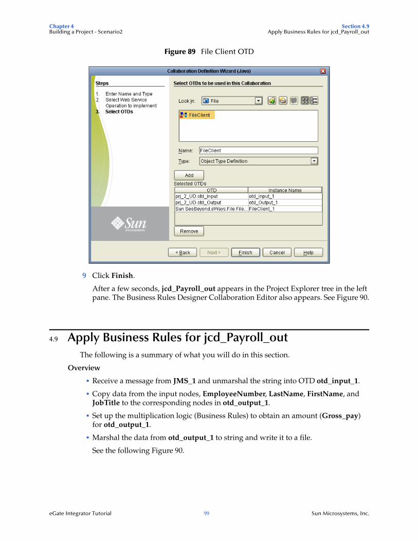
Chapter 4 Section 4.9Building a Project - Scenario2 Apply Business Rules for jcd_Payroll_out
eGate Integrator Tutorial 99 Sun Microsystems, Inc.
Figure 89 File Client OTD
9 Click Finish.
After a few seconds, jcd_Payroll_out appears in the Project Explorer tree in the left pane. The Business Rules Designer Collaboration Editor also appears. See Figure 90.
4.9 Apply Business Rules for jcd_Payroll_out The following is a summary of what you will do in this section.
Overview
Receive a message from JMS_1 and unmarshal the string into OTD otd_input_1.
Copy data from the input nodes, EmployeeNumber, LastName, FirstName, and JobTitle to the corresponding nodes in otd_output_1.
Set up the multiplication logic (Business Rules) to obtain an amount (Gross_pay) for otd_output_1.
Marshal the data from otd_output_1 to string and write it to a file.
See the following Figure 90.
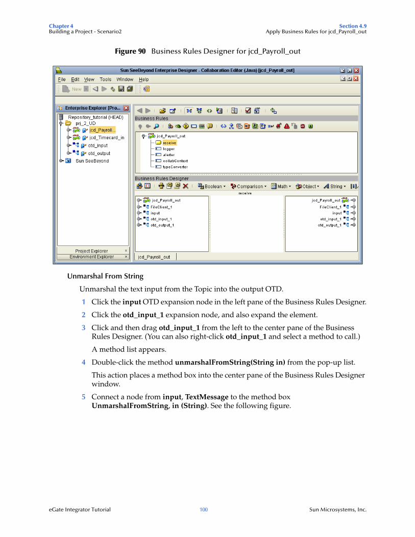
Chapter 4 Section 4.9Building a Project - Scenario2 Apply Business Rules for jcd_Payroll_out
eGate Integrator Tutorial 100 Sun Microsystems, Inc.
Figure 90 Business Rules Designer for jcd_Payroll_out
Unmarshal From String
Unmarshal the text input from the Topic into the output OTD.
1 Click the input OTD expansion node in the left pane of the Business Rules Designer.
2 Click the otd_input_1 expansion node, and also expand the element.
3 Click and then drag otd_input_1 from the left to the center pane of the Business Rules Designer. (You can also right-click otd_input_1 and select a method to call.)
A method list appears.
4 Double-click the method unmarshalFromString(String in) from the pop-up list.
This action places a method box into the center pane of the Business Rules Designer window.
5 Connect a node from input, TextMessage to the method box UnmarshalFromString, in (String). See the following figure.
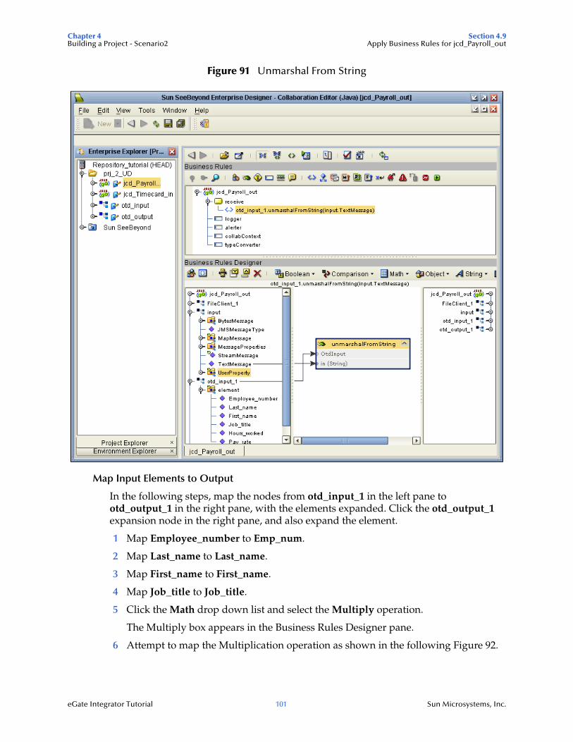
Chapter 4 Section 4.9Building a Project - Scenario2 Apply Business Rules for jcd_Payroll_out
eGate Integrator Tutorial 101 Sun Microsystems, Inc.
Figure 91 Unmarshal From String
Map Input Elements to Output
In the following steps, map the nodes from otd_input_1 in the left pane to otd_output_1 in the right pane, with the elements expanded. Click the otd_output_1 expansion node in the right pane, and also expand the element.
1 Map Employee_number to Emp_num.
2 Map Last_name to Last_name.
3 Map First_name to First_name.
4 Map Job_title to Job_title.
5 Click the Math drop down list and select the Multiply operation.
The Multiply box appears in the Business Rules Designer pane.
6 Attempt to map the Multiplication operation as shown in the following Figure 92.
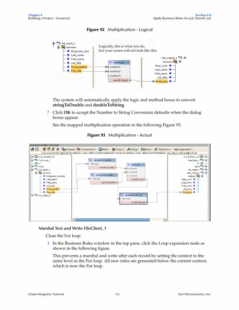
Chapter 4 Section 4.9Building a Project - Scenario2 Apply Business Rules for jcd_Payroll_out
eGate Integrator Tutorial 102 Sun Microsystems, Inc.
Figure 92 Multiplication - Logical
The system will automatically apply the logic and method boxes to convert stringToDouble and doubleToString.
7 Click OK to accept the Number to String Conversion defaults when the dialog boxes appear.
See the mapped multiplication operation in the following Figure 93.
Figure 93 Multiplication - Actual
Marshal Text and Write FileClient_1
Close the For loop.
1 In the Business Rules window in the top pane, click the Loop expansion node as shown in the following figure.
This prevents a marshal and write after each record by setting the context to the same level as the For loop. All new rules are generated below the current context, which is now the For loop.
Logically, this is what you do,but your screen will not look like this.
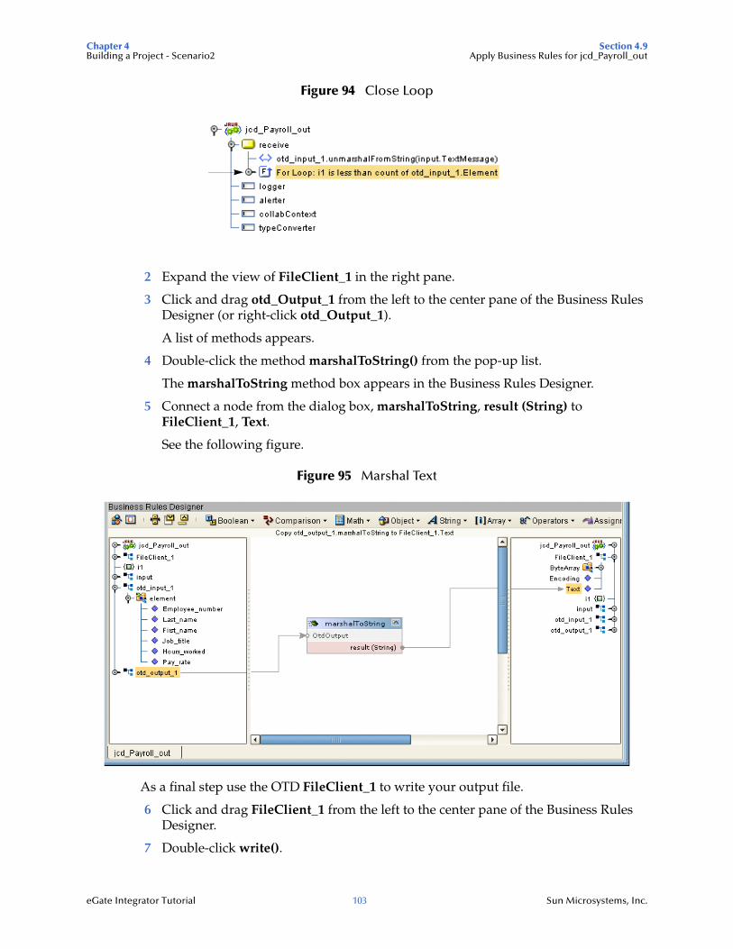
Chapter 4 Section 4.9Building a Project - Scenario2 Apply Business Rules for jcd_Payroll_out
eGate Integrator Tutorial 103 Sun Microsystems, Inc.
Figure 94 Close Loop
2 Expand the view of FileClient_1 in the right pane.
3 Click and drag otd_Output_1 from the left to the center pane of the Business Rules Designer (or right-click otd_Output_1).
A list of methods appears.
4 Double-click the method marshalToString() from the pop-up list.
The marshalToString method box appears in the Business Rules Designer.
5 Connect a node from the dialog box, marshalToString, result (String) to FileClient_1, Text.
See the following figure.
Figure 95 Marshal Text
As a final step use the OTD FileClient_1 to write your output file.
6 Click and drag FileClient_1 from the left to the center pane of the Business Rules Designer.
7 Double-click write().
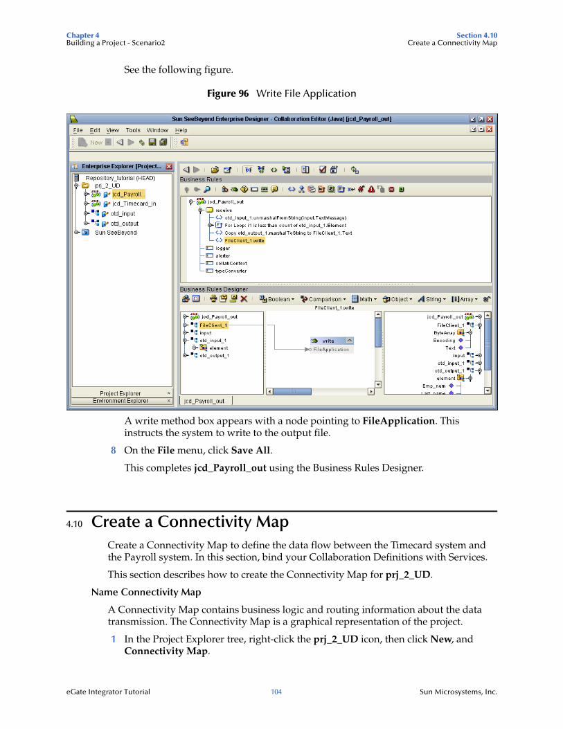
Chapter 4 Section 4.10Building a Project - Scenario2 Create a Connectivity Map
eGate Integrator Tutorial 104 Sun Microsystems, Inc.
See the following figure.
Figure 96 Write File Application
A write method box appears with a node pointing to FileApplication. This instructs the system to write to the output file.
8 On the File menu, click Save All.
This completes jcd_Payroll_out using the Business Rules Designer.
4.10 Create a Connectivity MapCreate a Connectivity Map to define the data flow between the Timecard system and the Payroll system. In this section, bind your Collaboration Definitions with Services.
This section describes how to create the Connectivity Map for prj_2_UD.
Name Connectivity Map
A Connectivity Map contains business logic and routing information about the data transmission. The Connectivity Map is a graphical representation of the project.
1 In the Project Explorer tree, right-click the prj_2_UD icon, then click New, and Connectivity Map.
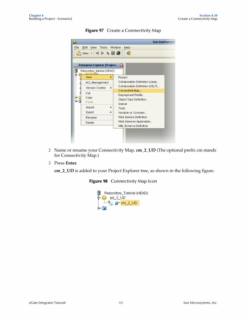
Chapter 4 Section 4.10Building a Project - Scenario2 Create a Connectivity Map
eGate Integrator Tutorial 105 Sun Microsystems, Inc.
Figure 97 Create a Connectivity Map
2 Name or rename your Connectivity Map, cm_2_UD (The optional prefix cm stands for Connectivity Map.)
3 Press Enter.
cm_2_UD is added to your Project Explorer tree, as shown in the following figure.
Figure 98 Connectivity Map Icon
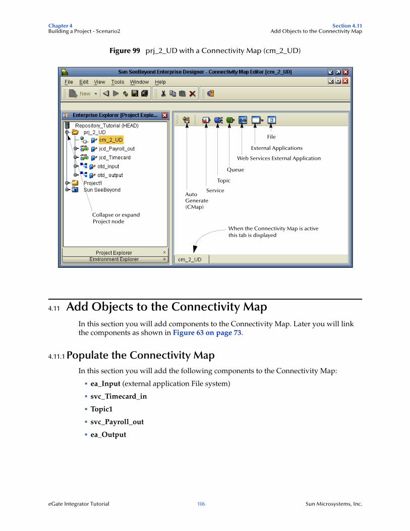
Chapter 4 Section 4.11Building a Project - Scenario2 Add Objects to the Connectivity Map
eGate Integrator Tutorial 106 Sun Microsystems, Inc.
Figure 99 prj_2_UD with a Connectivity Map (cm_2_UD)
4.11 Add Objects to the Connectivity MapIn this section you will add components to the Connectivity Map. Later you will link the components as shown in Figure 63 on page 73.
4.11.1 Populate the Connectivity MapIn this section you will add the following components to the Connectivity Map:
ea_Input (external application File system)
svc_Timecard_in
Topic1
svc_Payroll_out
ea_Output
Collapse or expandProject node
Queue
Topic
Web Services External Application
Service
When the Connectivity Map is activethis tab is displayed
File
External Applications
AutoGenerate(CMap)
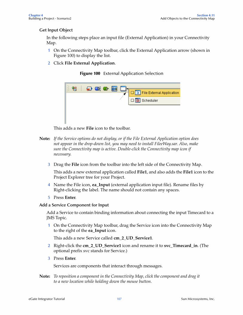
Chapter 4 Section 4.11Building a Project - Scenario2 Add Objects to the Connectivity Map
eGate Integrator Tutorial 107 Sun Microsystems, Inc.
Get Input Object
In the following steps place an input file (External Application) in your Connectivity Map.
1 On the Connectivity Map toolbar, click the External Application arrow (shown in Figure 100) to display the list.
2 Click File External Application.
Figure 100 External Application Selection
This adds a new File icon to the toolbar.
Note: If the Service options do not display, or if the File External Application option does not appear in the drop-down list, you may need to install FileeWay.sar. Also, make sure the Connectivity map is active. Double-click the Connectivity map icon if necessary.
3 Drag the File icon from the toolbar into the left side of the Connectivity Map.
This adds a new external application called File1, and also adds the File1 icon to the Project Explorer tree for your Project.
4 Name the File icon, ea_Input (external application input file). Rename files by Right-clicking the label. The name should not contain any spaces.
5 Press Enter.
Add a Service Component for Input
Add a Service to contain binding information about connecting the input Timecard to a JMS Topic.
1 On the Connectivity Map toolbar, drag the Service icon into the Connectivity Map to the right of the ea_Input icon.
This adds a new Service called cm_2_UD_Service1.
2 Right-click the cm_2_UD_Service1 icon and rename it to svc_Timecard_in. (The optional prefix svc stands for Service.)
3 Press Enter.
Services are components that interact through messages.
Note: To reposition a component in the Connectivity Map, click the component and drag it to a new location while holding down the mouse button.
Chapter 4 Section 4.11Building a Project - Scenario2 Add Objects to the Connectivity Map
eGate Integrator Tutorial 108 Sun Microsystems, Inc.
Get Topic
The JMS Topic conforms to the publish-and-subscribe messaging domain, where one publisher broadcasts messages to potentially many subscribers.
1 On the Connectivity Map toolbar, drag the Topic icon into the Connectivity Map to the right of the svc_Timecard_in icon.
This adds a new Topic called Topic1. Accept the default name, Topic1.
Get Service Component for Output
Add a Service to contain binding information about connecting the Topic to the output payroll File.
1 On the Connectivity Map toolbar, drag another Service icon into the Connectivity Map to the right of the Topic1 icon.
2 Rename the Service as svc_Payroll_out.
3 Press Enter.
Get Output Object
Place an output file (external application) in your Connectivity Map.
1 Drag another File icon into the Connectivity Map, and place it to the right of the svc_Payroll_out icon.
This icon represents your external application (output) file.
2 Name the file, ea_Output (external application output file). Rename the file by right-clicking the icon. (The name should not contain any spaces.)
3 Press Enter.
4 On the File menu, click Save.
4.11.2 Link Components in the Connectivity MapLinking the components creates a logical flow of data between External Applications via eWays. In this scenario use the Connectivity Map Generator button on the tool bar.
At this point, the Connectivity Map contains five unlinked objects. You are now ready to link them.
Define the Input Service
You define a Service by dragging a Collaboration Definition into a Service component. In the following steps you will bind a Collaboration to the svc_Timecard_in Service.
1 Double-click the Connectivity Map icon (if the Connectivity Map is not already displayed).
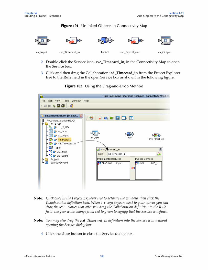
Chapter 4 Section 4.11Building a Project - Scenario2 Add Objects to the Connectivity Map
eGate Integrator Tutorial 109 Sun Microsystems, Inc.
Figure 101 Unlinked Objects in Connectivity Map
2 Double-click the Service icon, svc_Timecard_in, in the Connectivity Map to open the Service box.
3 Click and then drag the Collaboration jcd_Timecard_in from the Project Explorer tree to the Rule field in the open Service box as shown in the following figure.
Figure 102 Using the Drag-and-Drop Method
Note: Click once in the Project Explorer tree to activate the window, then click the Collaboration definition icon. When a + sign appears next to your cursor you can drag the icon. Notice that after you drag the Collaboration definition to the Rule field, the gear icons change from red to green to signify that the Service is defined.
Note: You may also drag the jcd_Timecard_in definition into the Service icon without opening the Service dialog box.
4 Click the close button to close the Service dialog box.
ea_Input svc_Timecard_in Topic1 svc_Payroll_out ea_Output
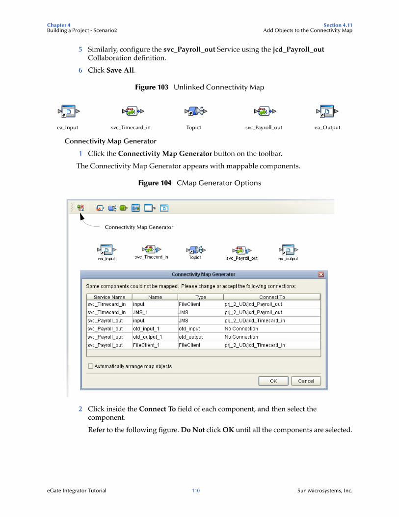
Chapter 4 Section 4.11Building a Project - Scenario2 Add Objects to the Connectivity Map
eGate Integrator Tutorial 110 Sun Microsystems, Inc.
5 Similarly, configure the svc_Payroll_out Service using the jcd_Payroll_out Collaboration definition.
6 Click Save All.
Figure 103 Unlinked Connectivity Map
Connectivity Map Generator
1 Click the Connectivity Map Generator button on the toolbar.
The Connectivity Map Generator appears with mappable components.
Figure 104 CMap Generator Options
2 Click inside the Connect To field of each component, and then select the component.
Refer to the following figure. Do Not click OK until all the components are selected.
ea_Input svc_Timecard_in Topic1 svc_Payroll_out ea_Output
Connectivity Map Generator
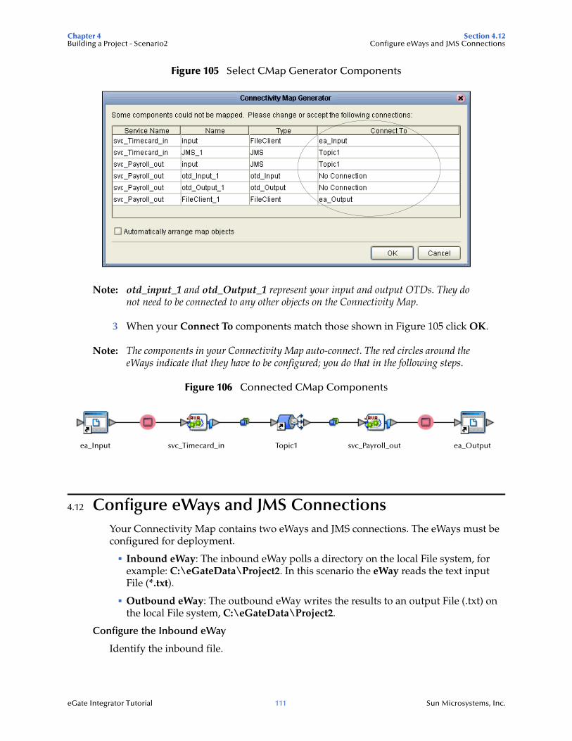
Chapter 4 Section 4.12Building a Project - Scenario2 Configure eWays and JMS Connections
eGate Integrator Tutorial 111 Sun Microsystems, Inc.
Figure 105 Select CMap Generator Components
Note: otd_input_1 and otd_Output_1 represent your input and output OTDs. They do not need to be connected to any other objects on the Connectivity Map.
3 When your Connect To components match those shown in Figure 105 click OK.
Note: The components in your Connectivity Map auto-connect. The red circles around the eWays indicate that they have to be configured; you do that in the following steps.
Figure 106 Connected CMap Components
4.12 Configure eWays and JMS ConnectionsYour Connectivity Map contains two eWays and JMS connections. The eWays must be configured for deployment.
Inbound eWay: The inbound eWay polls a directory on the local File system, for example: C:\eGateData\Project2. In this scenario the eWay reads the text input File (*.txt).
Outbound eWay: The outbound eWay writes the results to an output File (.txt) on the local File system, C:\eGateData\Project2.
Configure the Inbound eWay
Identify the inbound file.
ea_Input svc_Timecard_in Topic1 svc_Payroll_out ea_Output
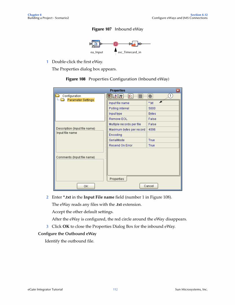
Chapter 4 Section 4.12Building a Project - Scenario2 Configure eWays and JMS Connections
eGate Integrator Tutorial 112 Sun Microsystems, Inc.
Figure 107 Inbound eWay
1 Double-click the first eWay.
The Properties dialog box appears.
Figure 108 Properties Configuration (Inbound eWay)
2 Enter *.txt in the Input File name field (number 1 in Figure 108).
The eWay reads any files with the .txt extension.
Accept the other default settings.
After the eWay is configured, the red circle around the eWay disappears.
3 Click OK to close the Properties Dialog Box for the inbound eWay.
Configure the Outbound eWay
Identify the outbound file.
ea_Input svc_Timecard_in
1
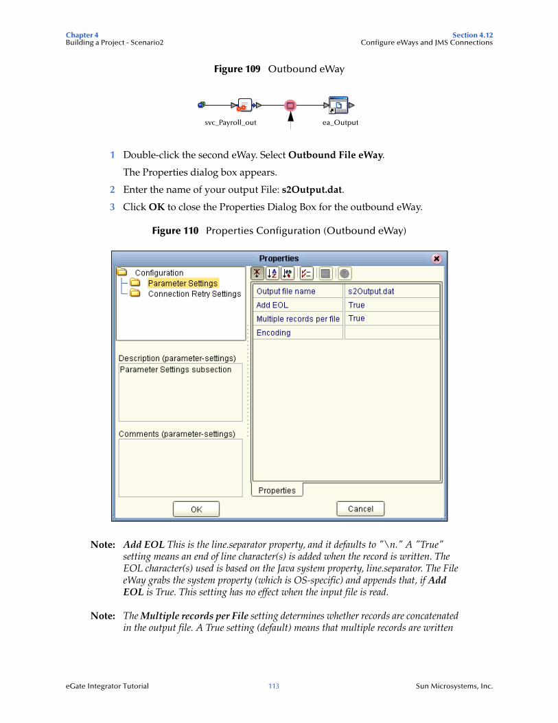
Chapter 4 Section 4.12Building a Project - Scenario2 Configure eWays and JMS Connections
eGate Integrator Tutorial 113 Sun Microsystems, Inc.
Figure 109 Outbound eWay
1 Double-click the second eWay. Select Outbound File eWay.
The Properties dialog box appears.
2 Enter the name of your output File: s2Output.dat.
3 Click OK to close the Properties Dialog Box for the outbound eWay.
Figure 110 Properties Configuration (Outbound eWay)
Note: Add EOL This is the line.separator property, and it defaults to "\n." A "True" setting means an end of line character(s) is added when the record is written. The EOL character(s) used is based on the Java system property, line.separator. The File eWay grabs the system property (which is OS-specific) and appends that, if Add EOL is True. This setting has no effect when the input file is read.
Note: The Multiple records per File setting determines whether records are concatenated in the output file. A True setting (default) means that multiple records are written
svc_Payroll_out ea_Output

Chapter 4 Section 4.12Building a Project - Scenario2 Configure eWays and JMS Connections
eGate Integrator Tutorial 114 Sun Microsystems, Inc.
in the same file. A False setting means that only one record is written to one file. See Multiple records per File (True or False) on page 58 in Scenario1.
JMS Client Configuration
The JMS Client Configuration icons appear on both sides of the Topic1 icon, as shown by the arrows in the figure below.
Figure 111 JMS Client Properties Icon
Select JMS Client Configuration
For this Tutorial accept the default configurations.
1 Double-click the first of the two JMS icons (see previous Figure 111).
The JMS Client properties dialog box appears. You can set the basic configuration and the connection security parameters here. In this tutorial, accept the defaults.
Figure 112 JMS Client Properties
2 Click OK to accept the defaults.
3 Repeat this step for the other JMS client configuration.
(Since you accepted the defaults, the previous steps were not required and are for illustrative purposes only.)
svc_Timecard_in Topic1
Chapter 4 Section 4.13Building a Project - Scenario2 Create an Environment
eGate Integrator Tutorial 115 Sun Microsystems, Inc.
You are now ready to deploy your Project in an Environment containing a Logical Host and External Applications.
4 On the File menu, click Save All.
Your project is now complete and ready for deployment.
4.13 Create an EnvironmentCreate a Logical Host and an External File System using Environment Explorer. First create an Environment. The Environment Explorer deploys resources required to implement a project and includes information about external systems that interact with eGate. If you already created an Environment in one of the Tutorial scenarios, you may use that same Environment.
Note: If you are using an existing Environment, you can also run this project in the same instance of the Logical Host (domain1 for example). But make sure you are using the correct input data, and make sure you are using the correct path to the data, as explained in this section.
An Environment is a collection of physical resources and their configurations that are used to host Project components. An Environment contains logical hosts and external systems.
Add Logical Host and Servers
1 Click View on the Menu bar. Click Environment Explorer (or click the Environment Explorer tab).
2 Right-click the Repository name (computer icon). Click New Environment.
3 Right-click Environment1 and rename it to Tutorial. Press Enter.
4 Right-click Tutorial. Click New, Logical Host.
This creates a LogicalHost1 box in the right pane.
Add an Integration Server
The Integration Server is a J2EE software platform that houses the business logic container used to run Collaborations and JCA connectors (eWays).
1 Right-click LogicalHost1 in the Enterprise Explorer window. Click New, SeeBeyond Integration Server.
IntegrationSvr1 appears in the LogicalHost1 box. Your Collaboration will be bound to this server.
Add a JMS IQ Manager
The JMS IQ Manager is a JMS-compliant, guaranteed delivery store, forwarding, and queueing Service.
1 Right-click LogicalHost1 in the Enterprise Explorer window. Click New, SeeBeyond JMS IQ Manager.
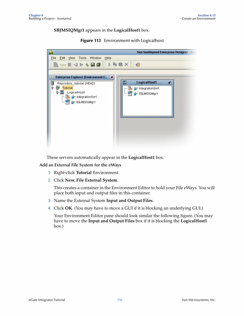
Chapter 4 Section 4.13Building a Project - Scenario2 Create an Environment
eGate Integrator Tutorial 116 Sun Microsystems, Inc.
SBJMSIQMgr1 appears in the LogicalHost1 box.
Figure 113 Environment with Logicalhost
These servers automatically appear in the LogicalHost1 box.
Add an External File System for the eWays
1 Right-click Tutorial Environment.
2 Click New, File External System.
This creates a container in the Environment Editor to hold your File eWays. You will place both input and output files in this container.
3 Name the External System Input and Output Files.
4 Click OK. (You may have to move a GUI if it is blocking an underlying GUI.)
Your Environment Editor pane should look similar the following figure. (You may have to move the Input and Output Files box if it is blocking the LogicalHost1 box.)
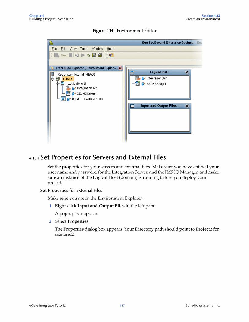
Chapter 4 Section 4.13Building a Project - Scenario2 Create an Environment
eGate Integrator Tutorial 117 Sun Microsystems, Inc.
Figure 114 Environment Editor
4.13.1 Set Properties for Servers and External FilesSet the properties for your servers and external files. Make sure you have entered your user name and password for the Integration Server, and the JMS IQ Manager, and make sure an instance of the Logical Host (domain) is running before you deploy your project.
Set Properties for External Files
Make sure you are in the Environment Explorer.
1 Right-click Input and Output Files in the left pane.
A pop-up box appears.
2 Select Properties.
The Properties dialog box appears. Your Directory path should point to Project2 for scenario2.
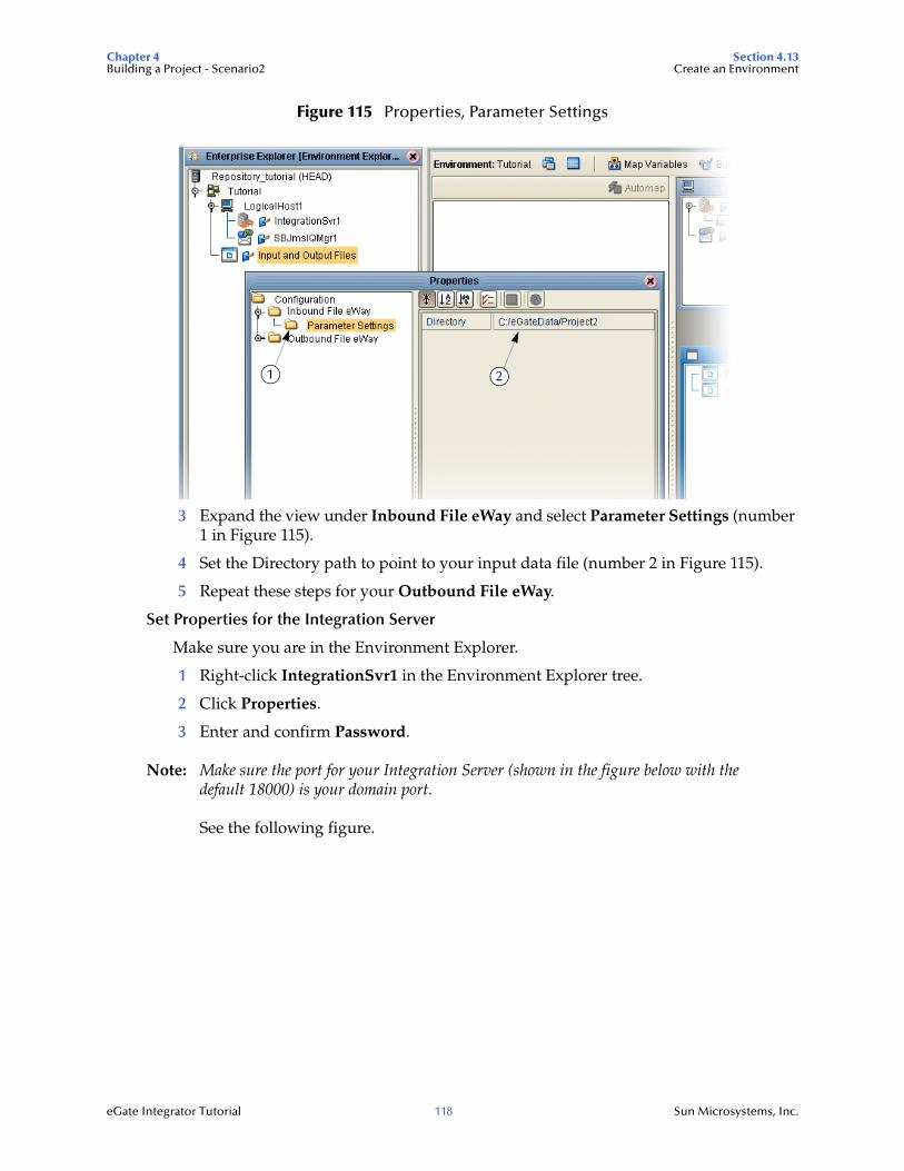
Chapter 4 Section 4.13Building a Project - Scenario2 Create an Environment
eGate Integrator Tutorial 118 Sun Microsystems, Inc.
Figure 115 Properties, Parameter Settings
3 Expand the view under Inbound File eWay and select Parameter Settings (number 1 in Figure 115).
4 Set the Directory path to point to your input data file (number 2 in Figure 115).
5 Repeat these steps for your Outbound File eWay.
Set Properties for the Integration Server
Make sure you are in the Environment Explorer.
1 Right-click IntegrationSvr1 in the Environment Explorer tree.
2 Click Properties.
3 Enter and confirm Password.
Note: Make sure the port for your Integration Server (shown in the figure below with the default 18000) is your domain port.
See the following figure.
21
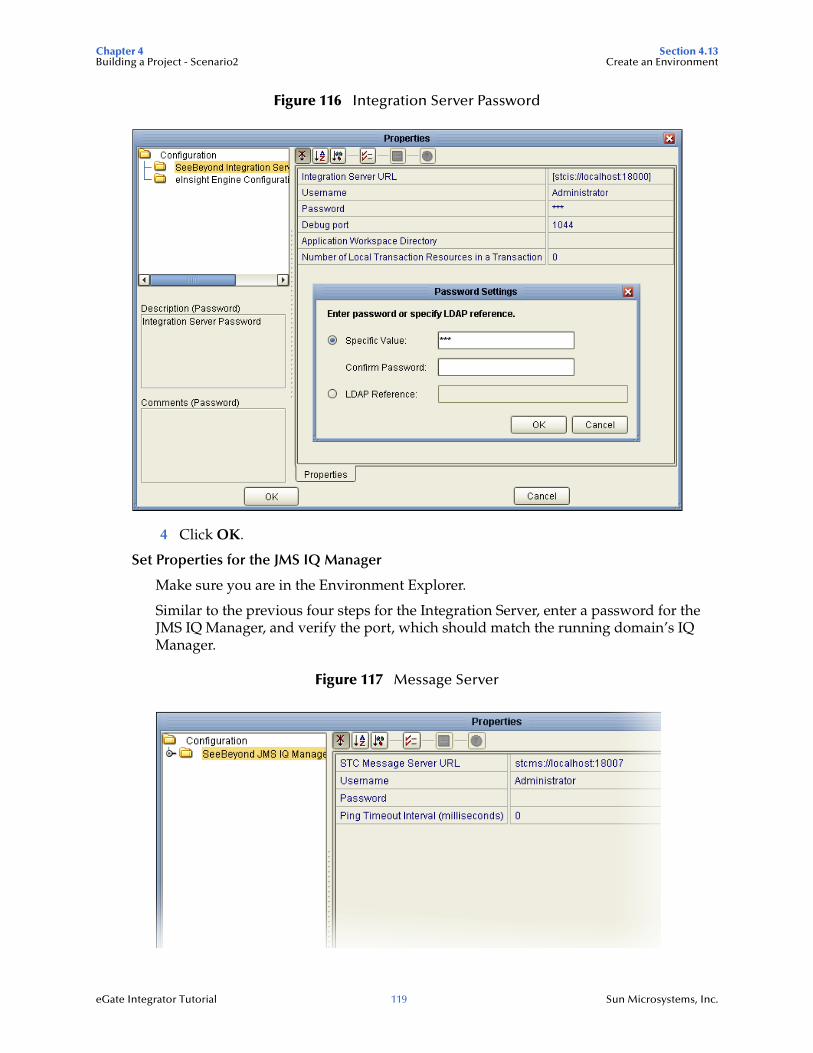
Chapter 4 Section 4.13Building a Project - Scenario2 Create an Environment
eGate Integrator Tutorial 119 Sun Microsystems, Inc.
Figure 116 Integration Server Password
4 Click OK.
Set Properties for the JMS IQ Manager
Make sure you are in the Environment Explorer.
Similar to the previous four steps for the Integration Server, enter a password for the JMS IQ Manager, and verify the port, which should match the running domain’s IQ Manager.
Figure 117 Message Server
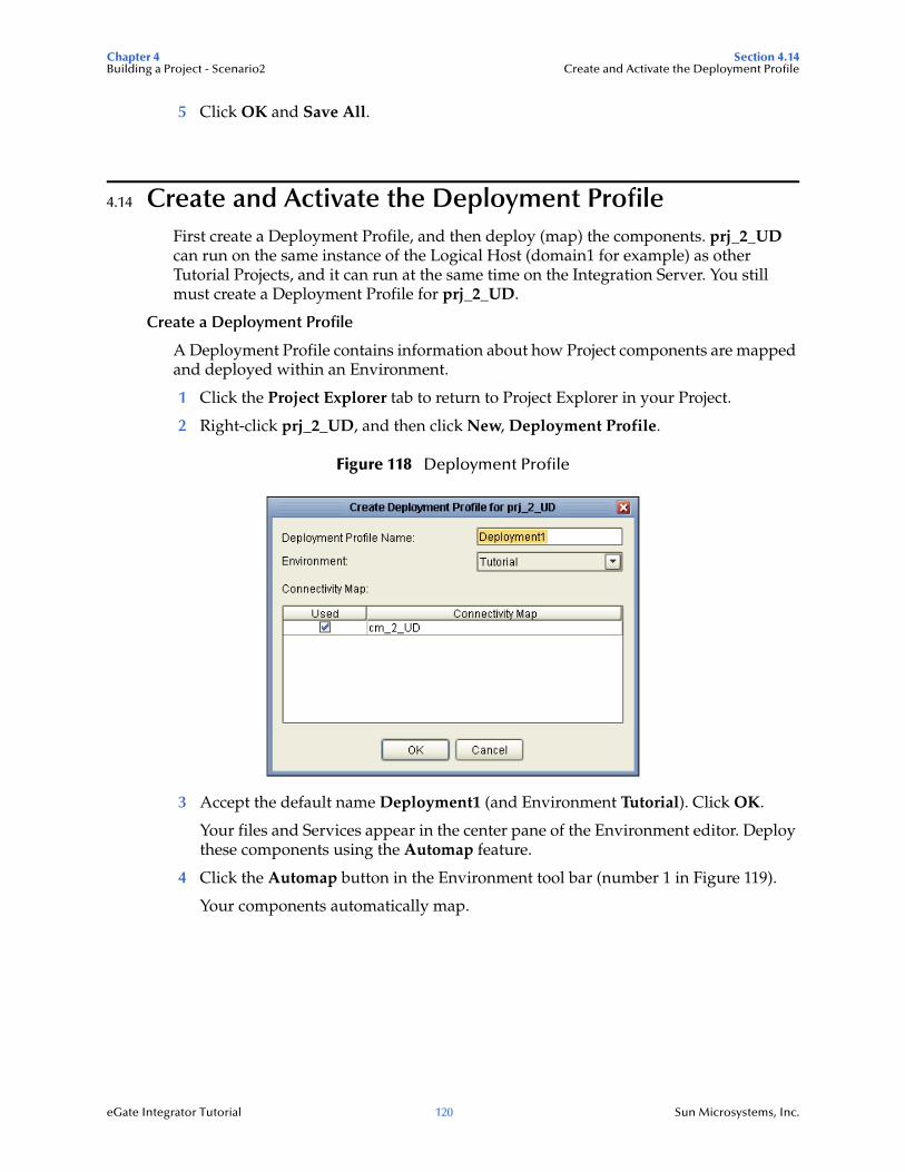
Chapter 4 Section 4.14Building a Project - Scenario2 Create and Activate the Deployment Profile
eGate Integrator Tutorial 120 Sun Microsystems, Inc.
5 Click OK and Save All.
4.14 Create and Activate the Deployment ProfileFirst create a Deployment Profile, and then deploy (map) the components. prj_2_UD can run on the same instance of the Logical Host (domain1 for example) as other Tutorial Projects, and it can run at the same time on the Integration Server. You still must create a Deployment Profile for prj_2_UD.
Create a Deployment Profile
A Deployment Profile contains information about how Project components are mapped and deployed within an Environment.
1 Click the Project Explorer tab to return to Project Explorer in your Project.
2 Right-click prj_2_UD, and then click New, Deployment Profile.
Figure 118 Deployment Profile
3 Accept the default name Deployment1 (and Environment Tutorial). Click OK.
Your files and Services appear in the center pane of the Environment editor. Deploy these components using the Automap feature.
4 Click the Automap button in the Environment tool bar (number 1 in Figure 119).
Your components automatically map.
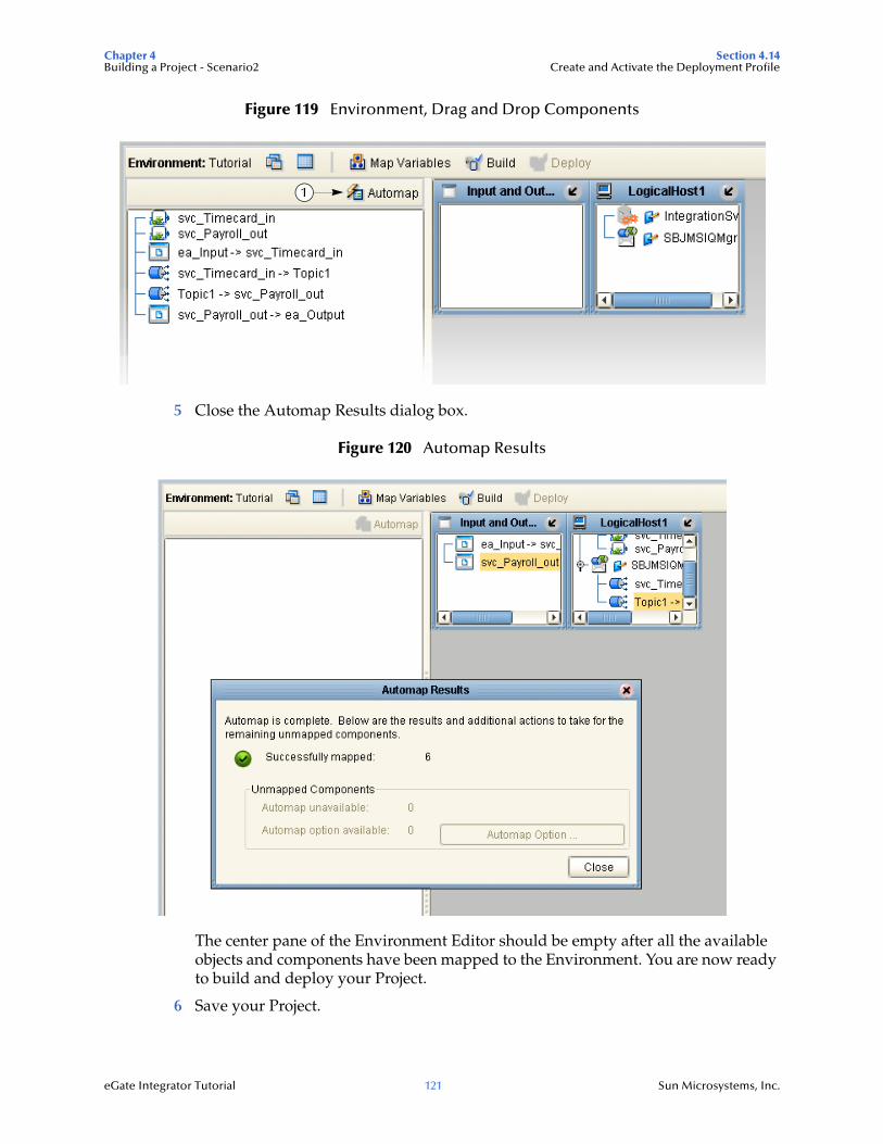
Chapter 4 Section 4.14Building a Project - Scenario2 Create and Activate the Deployment Profile
eGate Integrator Tutorial 121 Sun Microsystems, Inc.
Figure 119 Environment, Drag and Drop Components
5 Close the Automap Results dialog box.
Figure 120 Automap Results
The center pane of the Environment Editor should be empty after all the available objects and components have been mapped to the Environment. You are now ready to build and deploy your Project.
6 Save your Project.
1
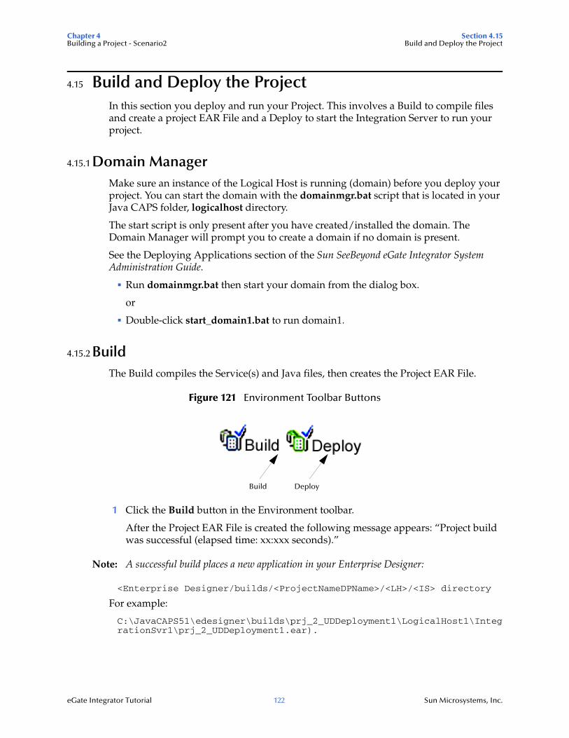
Chapter 4 Section 4.15Building a Project - Scenario2 Build and Deploy the Project
eGate Integrator Tutorial 122 Sun Microsystems, Inc.
4.15 Build and Deploy the ProjectIn this section you deploy and run your Project. This involves a Build to compile files and create a project EAR File and a Deploy to start the Integration Server to run your project.
4.15.1 Domain ManagerMake sure an instance of the Logical Host is running (domain) before you deploy your project. You can start the domain with the domainmgr.bat script that is located in your Java CAPS folder, logicalhost directory.
The start script is only present after you have created/installed the domain. The Domain Manager will prompt you to create a domain if no domain is present.
See the Deploying Applications section of the Sun SeeBeyond eGate Integrator System Administration Guide.
Run domainmgr.bat then start your domain from the dialog box.
or
Double-click start_domain1.bat to run domain1.
4.15.2 BuildThe Build compiles the Service(s) and Java files, then creates the Project EAR File.
Figure 121 Environment Toolbar Buttons
1 Click the Build button in the Environment toolbar.
After the Project EAR File is created the following message appears: “Project build was successful (elapsed time: xx:xxx seconds).”
Note: A successful build places a new application in your Enterprise Designer:
<Enterprise Designer/builds/<ProjectNameDPName>/<LH>/<IS> directory
For example:
C:\JavaCAPS51\edesigner\builds\prj_2_UDDeployment1\LogicalHost1\IntegrationSvr1\prj_2_UDDeployment1.ear).
Build Deploy
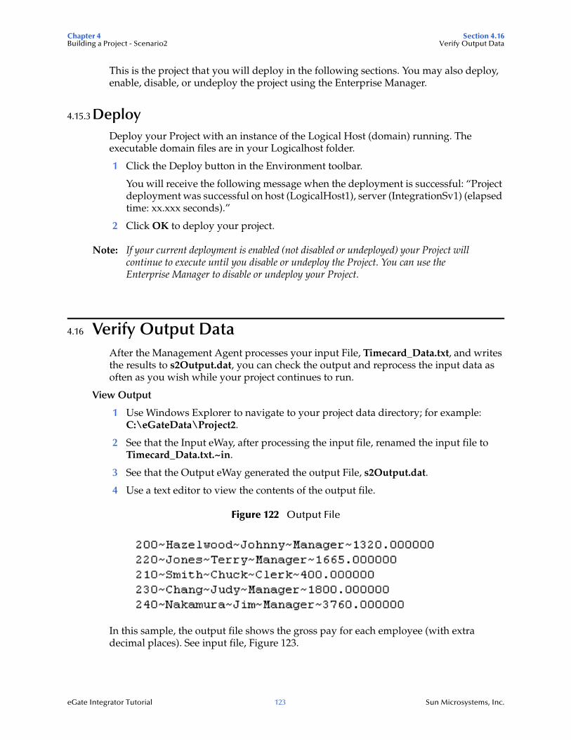
Chapter 4 Section 4.16Building a Project - Scenario2 Verify Output Data
eGate Integrator Tutorial 123 Sun Microsystems, Inc.
This is the project that you will deploy in the following sections. You may also deploy, enable, disable, or undeploy the project using the Enterprise Manager.
4.15.3 DeployDeploy your Project with an instance of the Logical Host (domain) running. The executable domain files are in your Logicalhost folder.
1 Click the Deploy button in the Environment toolbar.
You will receive the following message when the deployment is successful: “Project deployment was successful on host (LogicalHost1), server (IntegrationSv1) (elapsed time: xx.xxx seconds).”
2 Click OK to deploy your project.
Note: If your current deployment is enabled (not disabled or undeployed) your Project will continue to execute until you disable or undeploy the Project. You can use the Enterprise Manager to disable or undeploy your Project.
4.16 Verify Output DataAfter the Management Agent processes your input File, Timecard_Data.txt, and writes the results to s2Output.dat, you can check the output and reprocess the input data as often as you wish while your project continues to run.
View Output
1 Use Windows Explorer to navigate to your project data directory; for example: C:\eGateData\Project2.
2 See that the Input eWay, after processing the input file, renamed the input file to Timecard_Data.txt.~in.
3 See that the Output eWay generated the output File, s2Output.dat.
4 Use a text editor to view the contents of the output file.
Figure 122 Output File
In this sample, the output file shows the gross pay for each employee (with extra decimal places). See input file, Figure 123.
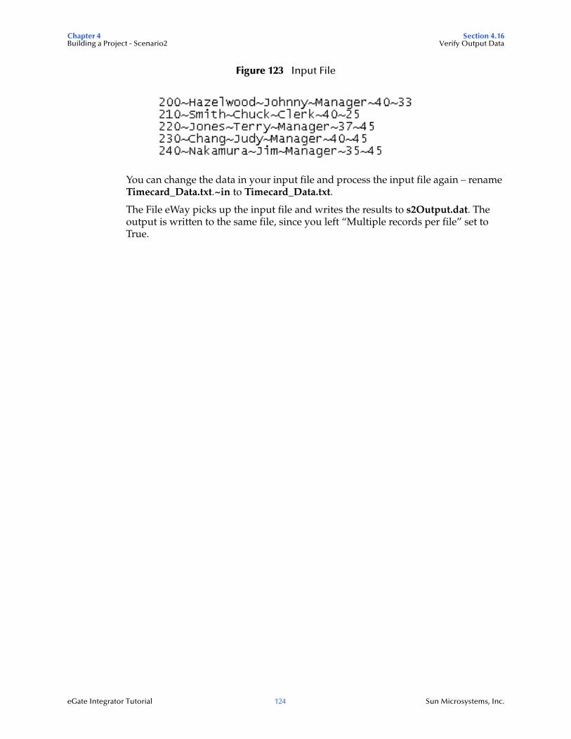
Chapter 4 Section 4.16Building a Project - Scenario2 Verify Output Data
eGate Integrator Tutorial 124 Sun Microsystems, Inc.
Figure 123 Input File
You can change the data in your input file and process the input file again – rename Timecard_Data.txt.~in to Timecard_Data.txt.
The File eWay picks up the input file and writes the results to s2Output.dat. The output is written to the same file, since you left “Multiple records per file” set to True.
eGate Integrator Tutorial 125 Sun Microsystems, Inc.
Chapter 5
Building a Project - Scenario3
5.0.1 Using XSD Objects to Generate XSD NodesThis Tutorial provides step-by-step procedures for creating and testing an eGate Project using XSDs (XML Schema Definition). In this scenario you import XSDs as XSD Objects which are then exported to XSD Nodes that are used in this Project.
This Project addresses a simple business challenge where an input timecard File is read and a payroll workfile is output.
What’s in This Chapter
Business Challenge on page 125
Sample Data for Project3 on page 127
Create a New Project on page 129
Import a Schema Definition on page 131
Export Schema Definitions to XSD Nodes on page 138
Apply Business Rules on page 146
Create a Connectivity Map on page 153
Configure the eWays on page 158
Create an Environment on page 160
Create Deployment Profile on page 163
Build and Deploy the Project on page 165
Verify Output Data on page 169
5.1 Business ChallengeThe Project described in this chapter provides a solution to the following business challenge:
In this very simple scenario FirstName and LastName from the input file are concatenated into the field FullName in the output file, and PayAmount is calculated based on multiplying HoursWorked times Rate.
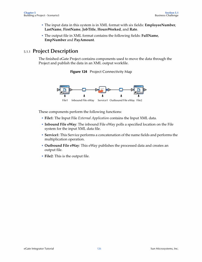
Chapter 5 Section 5.1Building a Project - Scenario3 Business Challenge
eGate Integrator Tutorial 126 Sun Microsystems, Inc.
The input data in this system is in XML format with six fields: EmployeeNumber, LastName, FirstName, JobTitle, HoursWorked, and Rate.
The output file in XML format contains the following fields: FullName, EmpNumber and PayAmount.
5.1.1 Project DescriptionThe finished eGate Project contains components used to move the data through the Project and publish the data in an XML output workfile.
Figure 124 Project Connectivity Map
These components perform the following functions:
File1: The Input File External Application contains the Input XML data.
Inbound File eWay: The inbound File eWay polls a specified location on the File system for the input XML data file.
Service1: This Service performs a concatenation of the name fields and performs the multiplication operation.
Outbound File eWay: This eWay publishes the processed data and creates an output file.
File2: This is the output file.
File1 Service1 File2Inbound File eWay Outbound File eWay
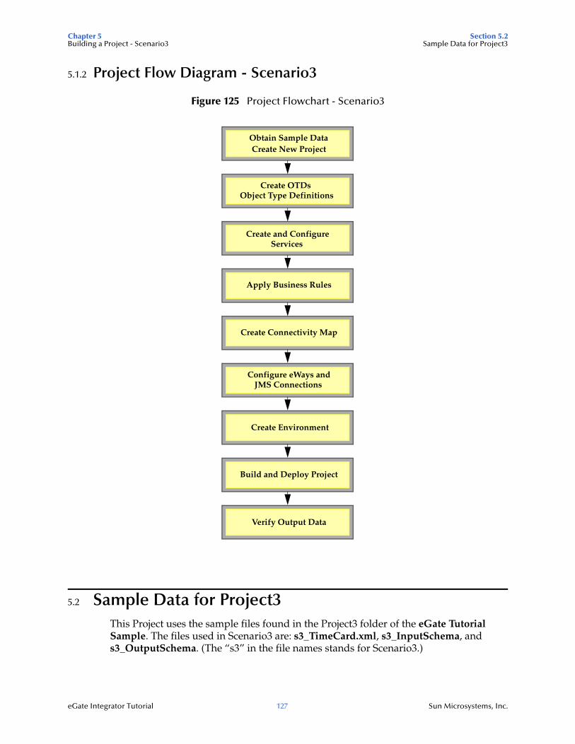
Chapter 5 Section 5.2Building a Project - Scenario3 Sample Data for Project3
eGate Integrator Tutorial 127 Sun Microsystems, Inc.
5.1.2 Project Flow Diagram - Scenario3
Figure 125 Project Flowchart - Scenario3
5.2 Sample Data for Project3This Project uses the sample files found in the Project3 folder of the eGate Tutorial Sample. The files used in Scenario3 are: s3_TimeCard.xml, s3_InputSchema, and s3_OutputSchema. (The “s3” in the file names stands for Scenario3.)
Obtain Sample DataCreate New Project
Create OTDsObject Type Definitions
Apply Business Rules
Create Connectivity Map
Configure eWays andJMS Connections
Create Environment
Build and Deploy Project
Verify Output Data
Create and ConfigureServices
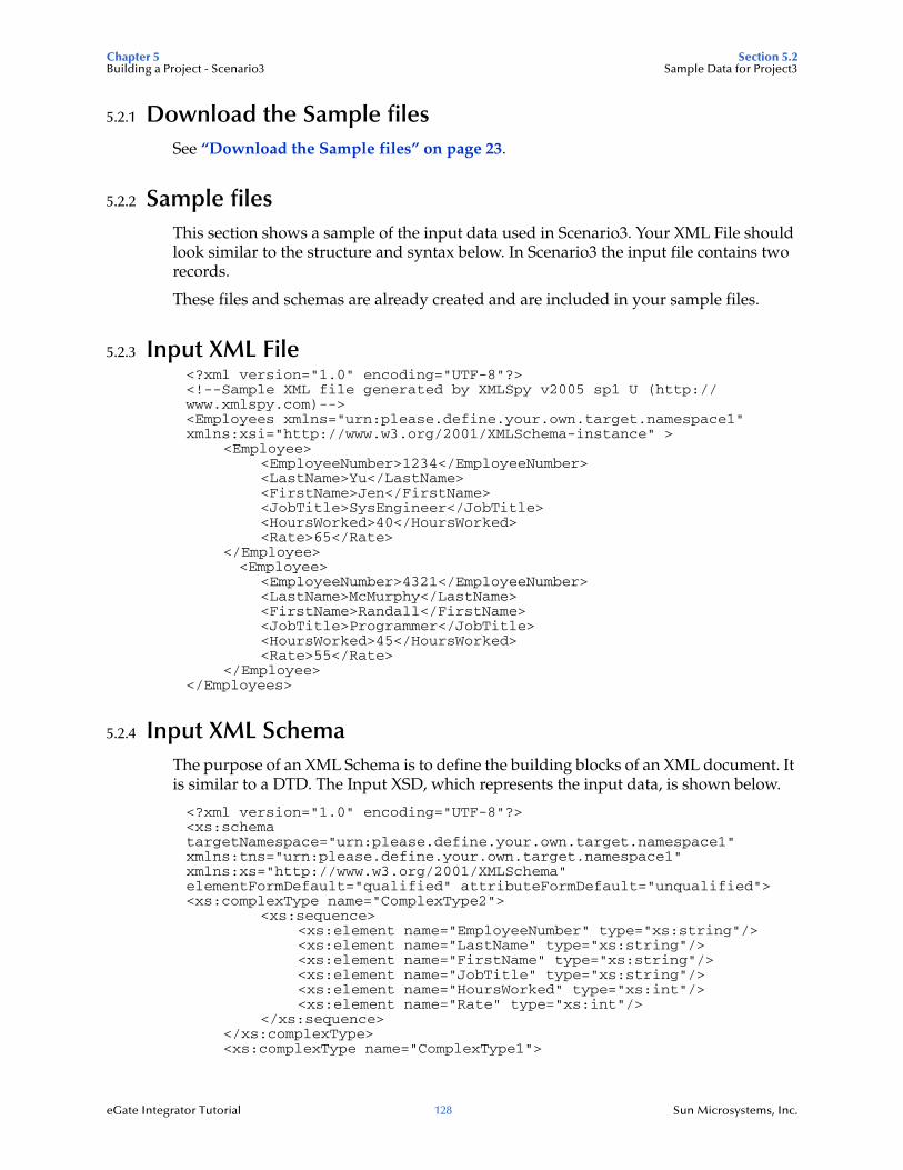
Chapter 5 Section 5.2Building a Project - Scenario3 Sample Data for Project3
eGate Integrator Tutorial 128 Sun Microsystems, Inc.
5.2.1 Download the Sample filesSee “Download the Sample files” on page 23.
5.2.2 Sample filesThis section shows a sample of the input data used in Scenario3. Your XML File should look similar to the structure and syntax below. In Scenario3 the input file contains two records.
These files and schemas are already created and are included in your sample files.
5.2.3 Input XML File<?xml version="1.0" encoding="UTF-8"?><!--Sample XML file generated by XMLSpy v2005 sp1 U (http://www.xmlspy.com)--><Employees xmlns="urn:please.define.your.own.target.namespace1" xmlns:xsi="http://www.w3.org/2001/XMLSchema-instance" >
<Employee><EmployeeNumber>1234</EmployeeNumber><LastName>Yu</LastName><FirstName>Jen</FirstName><JobTitle>SysEngineer</JobTitle><HoursWorked>40</HoursWorked><Rate>65</Rate>
</Employee> <Employee>
<EmployeeNumber>4321</EmployeeNumber><LastName>McMurphy</LastName><FirstName>Randall</FirstName><JobTitle>Programmer</JobTitle><HoursWorked>45</HoursWorked><Rate>55</Rate>
</Employee></Employees>
5.2.4 Input XML SchemaThe purpose of an XML Schema is to define the building blocks of an XML document. It is similar to a DTD. The Input XSD, which represents the input data, is shown below.
<?xml version="1.0" encoding="UTF-8"?><xs:schema targetNamespace="urn:please.define.your.own.target.namespace1" xmlns:tns="urn:please.define.your.own.target.namespace1" xmlns:xs="http://www.w3.org/2001/XMLSchema" elementFormDefault="qualified" attributeFormDefault="unqualified"><xs:complexType name="ComplexType2">
<xs:sequence><xs:element name="EmployeeNumber" type="xs:string"/><xs:element name="LastName" type="xs:string"/><xs:element name="FirstName" type="xs:string"/><xs:element name="JobTitle" type="xs:string"/><xs:element name="HoursWorked" type="xs:int"/><xs:element name="Rate" type="xs:int"/>
</xs:sequence></xs:complexType><xs:complexType name="ComplexType1">
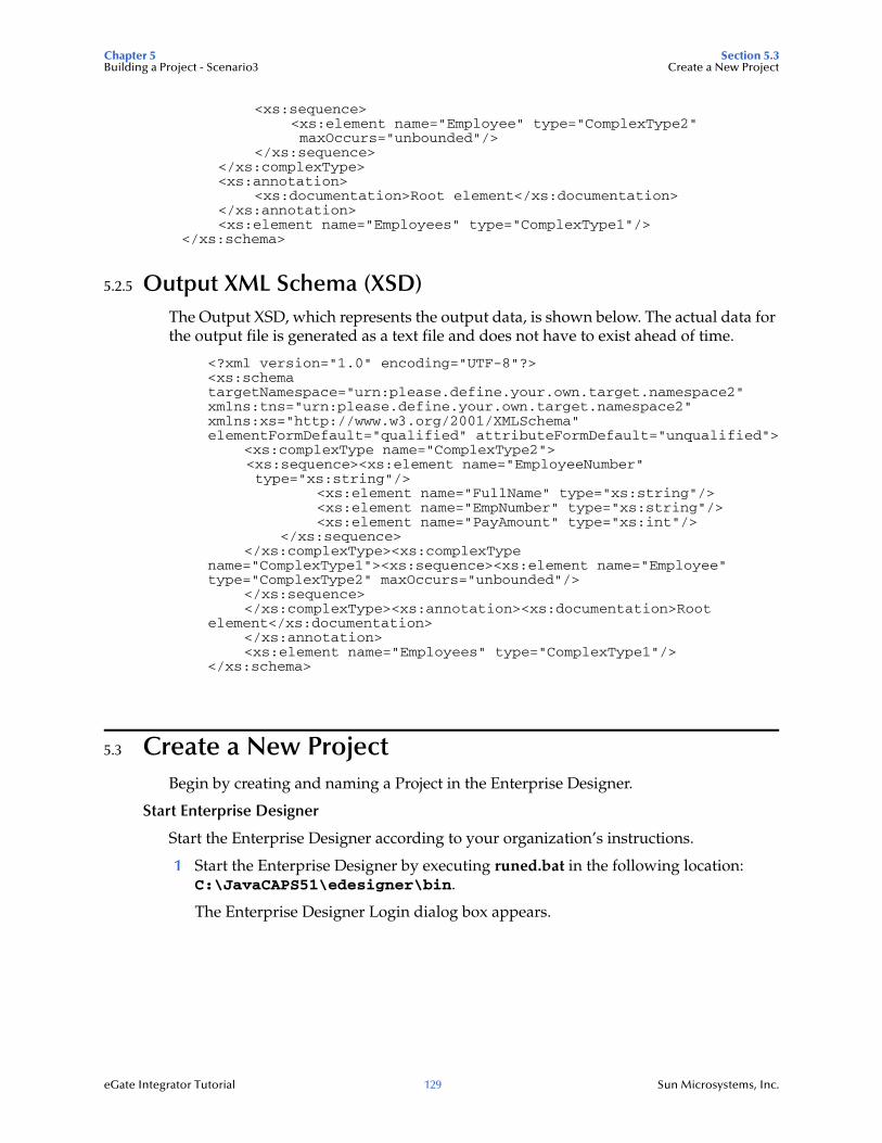
Chapter 5 Section 5.3Building a Project - Scenario3 Create a New Project
eGate Integrator Tutorial 129 Sun Microsystems, Inc.
<xs:sequence><xs:element name="Employee" type="ComplexType2" maxOccurs="unbounded"/>
</xs:sequence></xs:complexType><xs:annotation>
<xs:documentation>Root element</xs:documentation></xs:annotation><xs:element name="Employees" type="ComplexType1"/>
</xs:schema>
5.2.5 Output XML Schema (XSD)The Output XSD, which represents the output data, is shown below. The actual data for the output file is generated as a text file and does not have to exist ahead of time.
<?xml version="1.0" encoding="UTF-8"?><xs:schema targetNamespace="urn:please.define.your.own.target.namespace2" xmlns:tns="urn:please.define.your.own.target.namespace2" xmlns:xs="http://www.w3.org/2001/XMLSchema" elementFormDefault="qualified" attributeFormDefault="unqualified">
<xs:complexType name="ComplexType2"> <xs:sequence><xs:element name="EmployeeNumber" type="xs:string"/>
<xs:element name="FullName" type="xs:string"/><xs:element name="EmpNumber" type="xs:string"/><xs:element name="PayAmount" type="xs:int"/>
</xs:sequence></xs:complexType><xs:complexType
name="ComplexType1"><xs:sequence><xs:element name="Employee" type="ComplexType2" maxOccurs="unbounded"/>
</xs:sequence></xs:complexType><xs:annotation><xs:documentation>Root
element</xs:documentation></xs:annotation><xs:element name="Employees" type="ComplexType1"/>
</xs:schema>
5.3 Create a New ProjectBegin by creating and naming a Project in the Enterprise Designer.
Start Enterprise Designer
Start the Enterprise Designer according to your organization’s instructions.
1 Start the Enterprise Designer by executing runed.bat in the following location: C:\JavaCAPS51\edesigner\bin.
The Enterprise Designer Login dialog box appears.
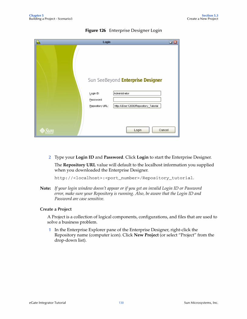
Chapter 5 Section 5.3Building a Project - Scenario3 Create a New Project
eGate Integrator Tutorial 130 Sun Microsystems, Inc.
Figure 126 Enterprise Designer Login
2 Type your Login ID and Password. Click Login to start the Enterprise Designer.
The Repository URL value will default to the localhost information you supplied when you downloaded the Enterprise Designer.
http://<localhost>:<port_number>/Repository_tutorial.
Note: If your login window doesn’t appear or if you get an invalid Login ID or Password error, make sure your Repository is running. Also, be aware that the Login ID and Password are case sensitive.
Create a Project
A Project is a collection of logical components, configurations, and files that are used to solve a business problem.
1 In the Enterprise Explorer pane of the Enterprise Designer, right-click the Repository name (computer icon). Click New Project (or select “Project” from the drop-down list).
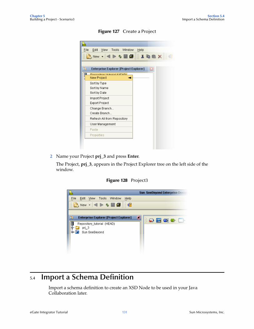
Chapter 5 Section 5.4Building a Project - Scenario3 Import a Schema Definition
eGate Integrator Tutorial 131 Sun Microsystems, Inc.
Figure 127 Create a Project
2 Name your Project prj_3 and press Enter.
The Project, prj_3, appears in the Project Explorer tree on the left side of the window.
Figure 128 Project3
5.4 Import a Schema DefinitionImport a schema definition to create an XSD Node to be used in your Java Collaboration later.
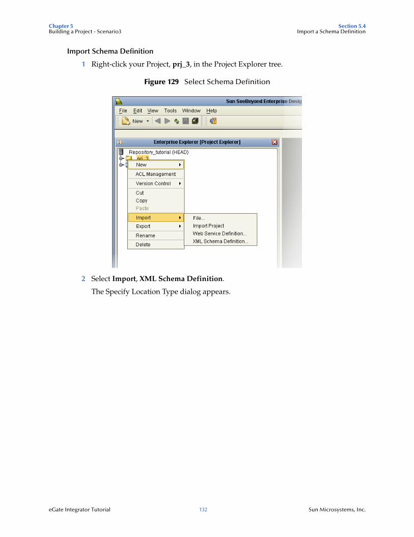
Chapter 5 Section 5.4Building a Project - Scenario3 Import a Schema Definition
eGate Integrator Tutorial 132 Sun Microsystems, Inc.
Import Schema Definition
1 Right-click your Project, prj_3, in the Project Explorer tree.
Figure 129 Select Schema Definition
2 Select Import, XML Schema Definition.
The Specify Location Type dialog appears.
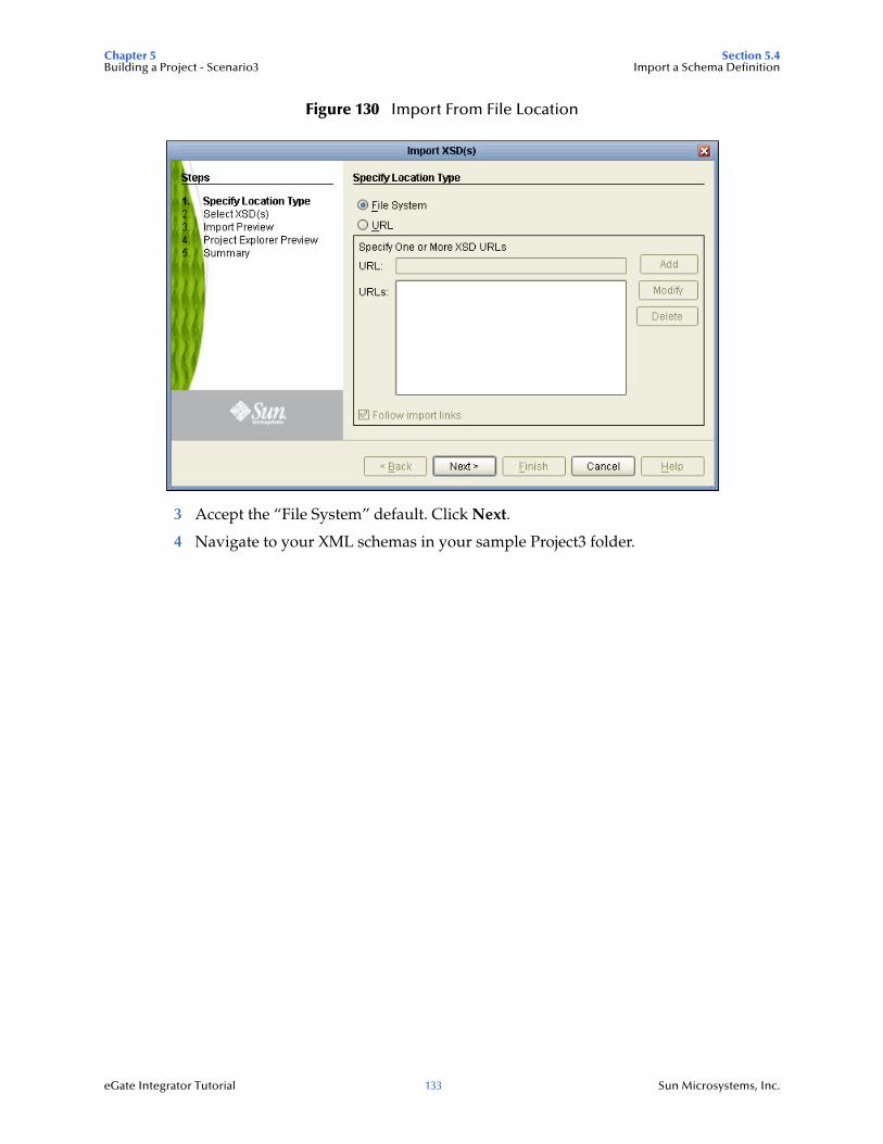
Chapter 5 Section 5.4Building a Project - Scenario3 Import a Schema Definition
eGate Integrator Tutorial 133 Sun Microsystems, Inc.
Figure 130 Import From File Location
3 Accept the “File System” default. Click Next.
4 Navigate to your XML schemas in your sample Project3 folder.
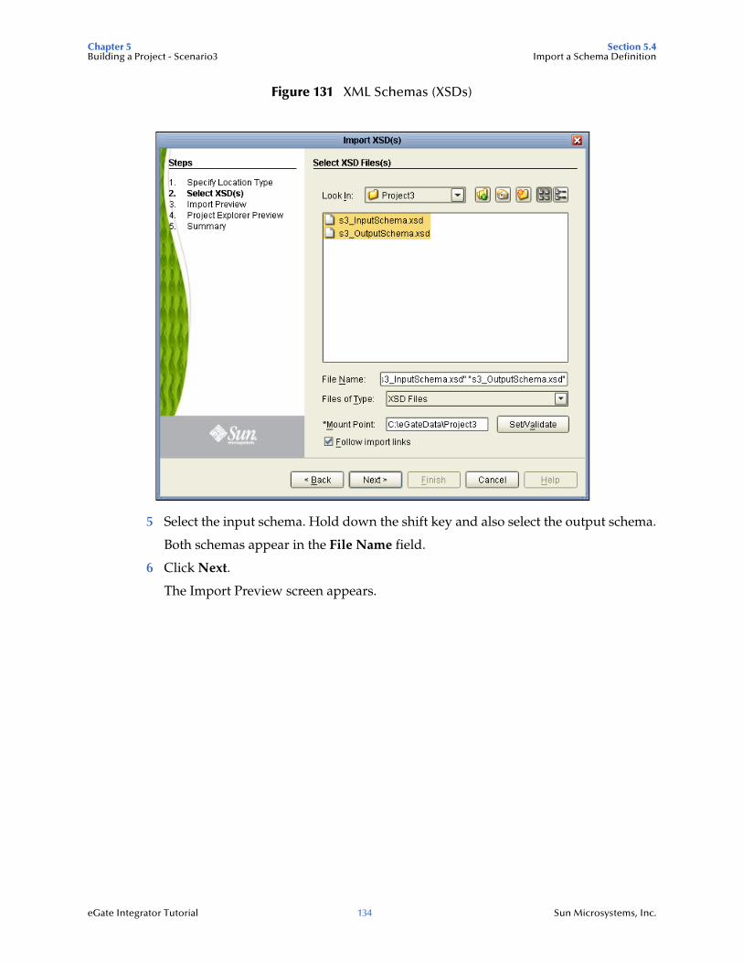
Chapter 5 Section 5.4Building a Project - Scenario3 Import a Schema Definition
eGate Integrator Tutorial 134 Sun Microsystems, Inc.
Figure 131 XML Schemas (XSDs)
5 Select the input schema. Hold down the shift key and also select the output schema.
Both schemas appear in the File Name field.
6 Click Next.
The Import Preview screen appears.
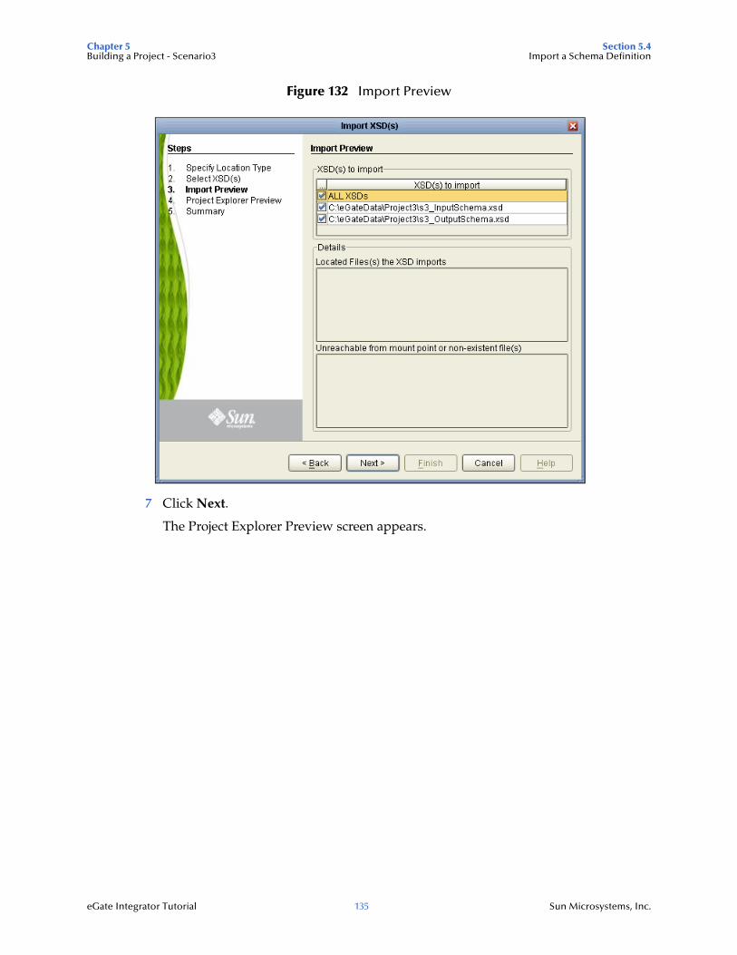
Chapter 5 Section 5.4Building a Project - Scenario3 Import a Schema Definition
eGate Integrator Tutorial 135 Sun Microsystems, Inc.
Figure 132 Import Preview
7 Click Next.
The Project Explorer Preview screen appears.
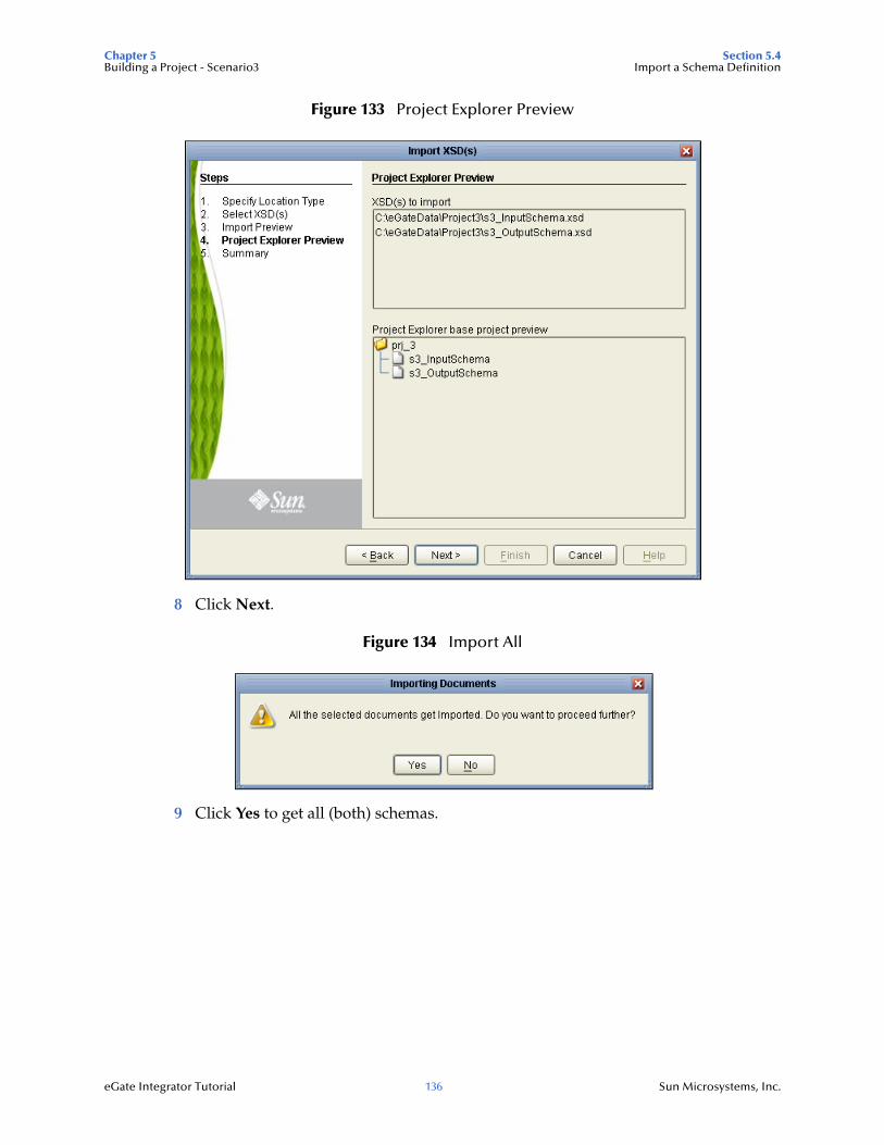
Chapter 5 Section 5.4Building a Project - Scenario3 Import a Schema Definition
eGate Integrator Tutorial 136 Sun Microsystems, Inc.
Figure 133 Project Explorer Preview
8 Click Next.
Figure 134 Import All
9 Click Yes to get all (both) schemas.
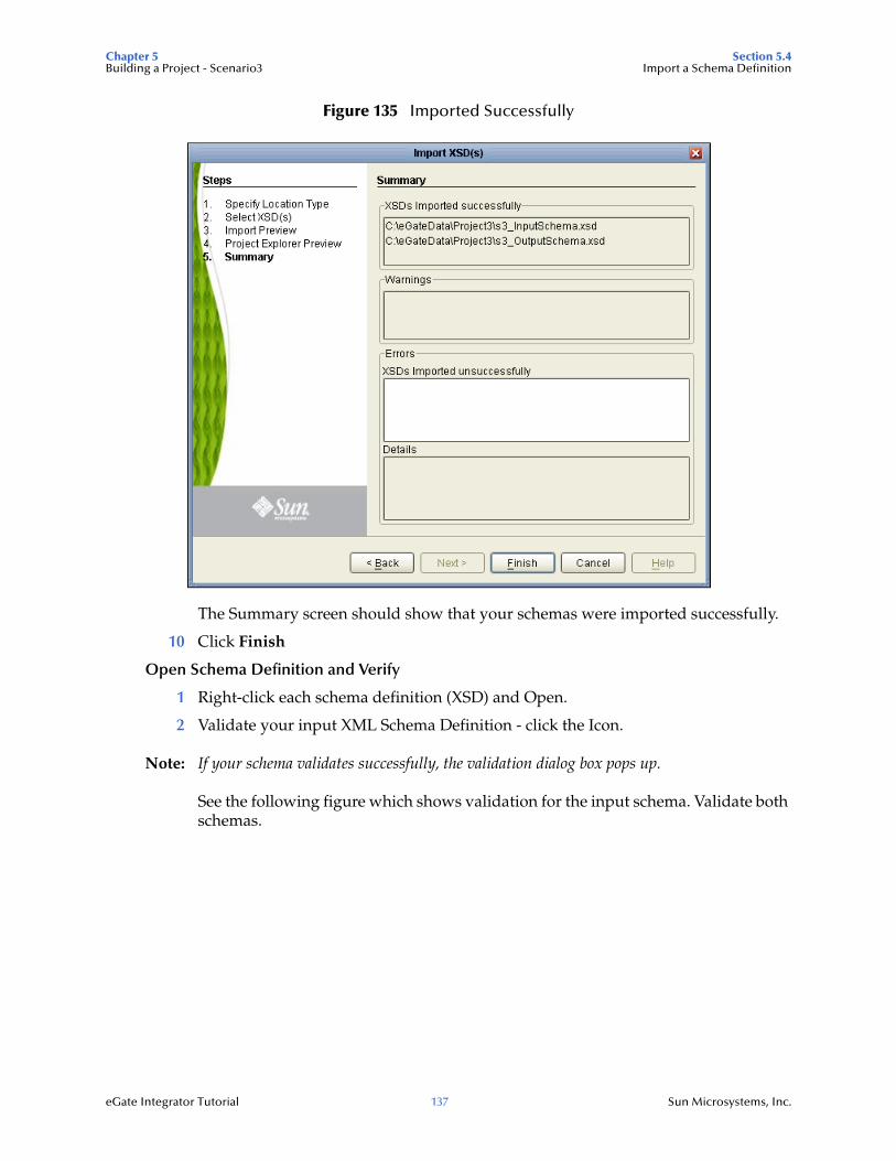
Chapter 5 Section 5.4Building a Project - Scenario3 Import a Schema Definition
eGate Integrator Tutorial 137 Sun Microsystems, Inc.
Figure 135 Imported Successfully
The Summary screen should show that your schemas were imported successfully.
10 Click Finish
Open Schema Definition and Verify
1 Right-click each schema definition (XSD) and Open.
2 Validate your input XML Schema Definition - click the Icon.
Note: If your schema validates successfully, the validation dialog box pops up.
See the following figure which shows validation for the input schema. Validate both schemas.
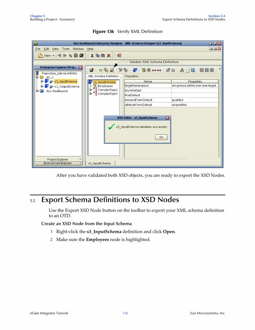
Chapter 5 Section 5.5Building a Project - Scenario3 Export Schema Definitions to XSD Nodes
eGate Integrator Tutorial 138 Sun Microsystems, Inc.
Figure 136 Verify XML Definition
After you have validated both XSD objects, you are ready to export the XSD Nodes.
5.5 Export Schema Definitions to XSD NodesUse the Export XSD Node button on the toolbar to export your XML schema definition to an OTD.
Create an XSD Node from the Input Schema
1 Right-click the s3_InputSchema definition and click Open.
2 Make sure the Employees node is highlighted.
Validate XML Schema Definition
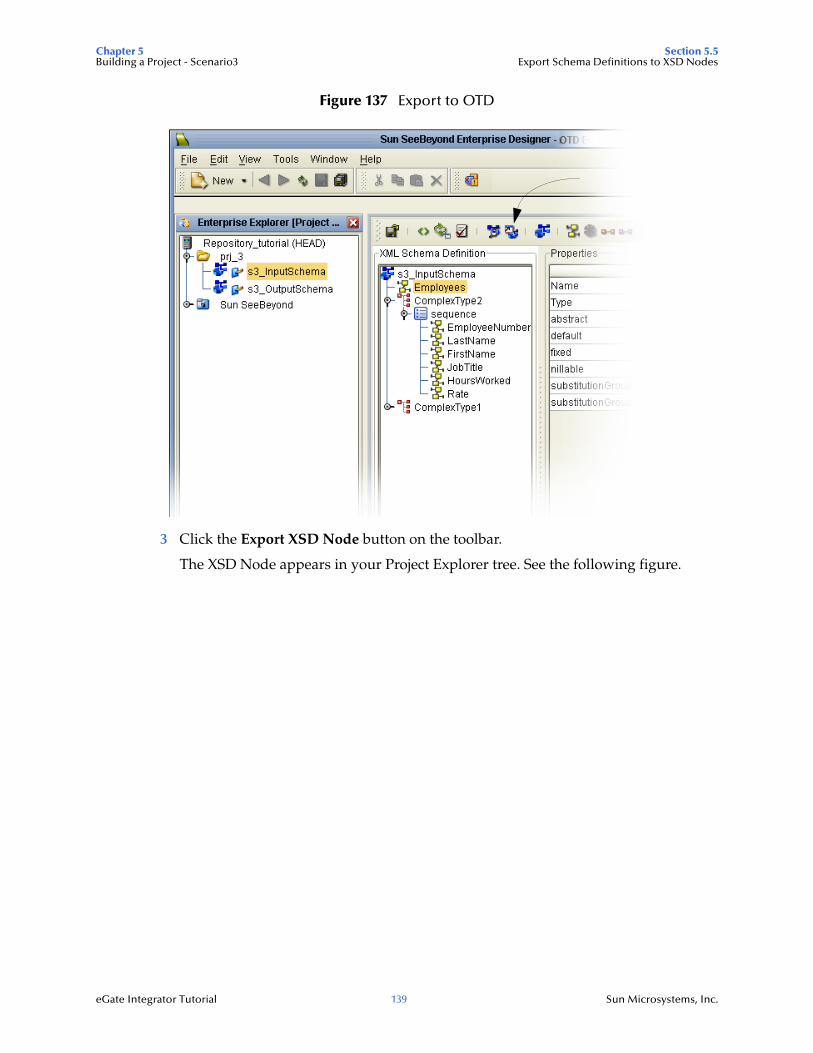
Chapter 5 Section 5.5Building a Project - Scenario3 Export Schema Definitions to XSD Nodes
eGate Integrator Tutorial 139 Sun Microsystems, Inc.
Figure 137 Export to OTD
3 Click the Export XSD Node button on the toolbar.
The XSD Node appears in your Project Explorer tree. See the following figure.
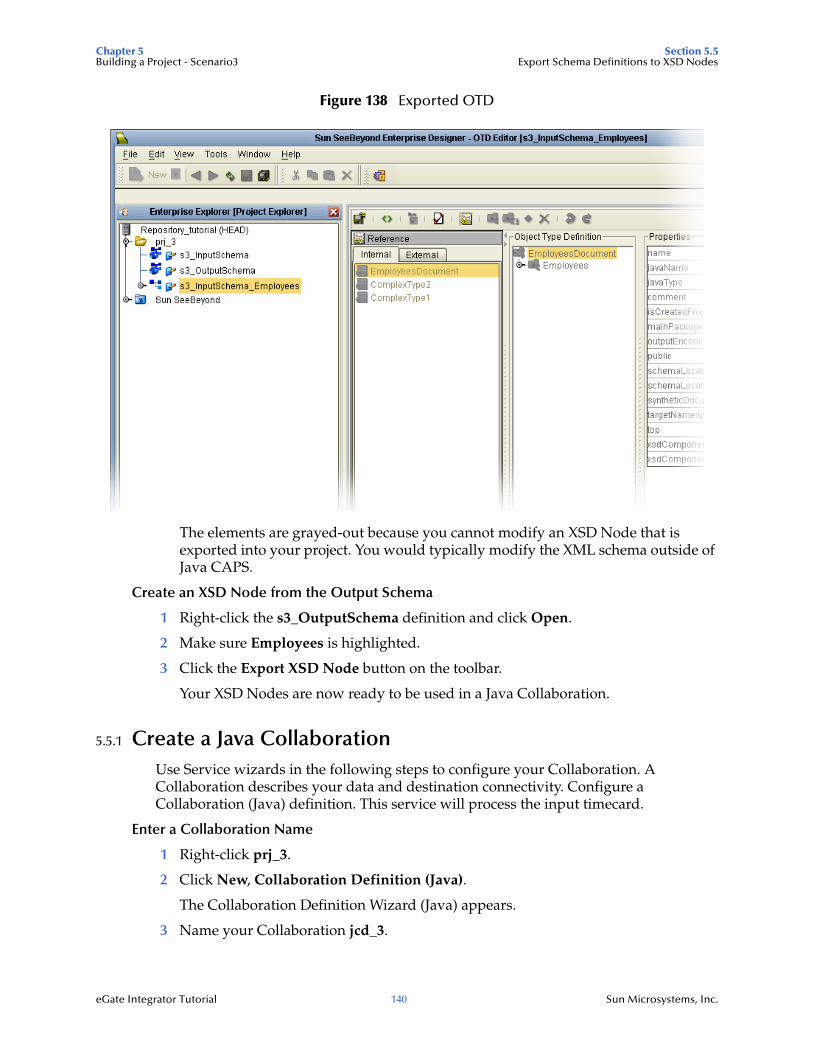
Chapter 5 Section 5.5Building a Project - Scenario3 Export Schema Definitions to XSD Nodes
eGate Integrator Tutorial 140 Sun Microsystems, Inc.
Figure 138 Exported OTD
The elements are grayed-out because you cannot modify an XSD Node that is exported into your project. You would typically modify the XML schema outside of Java CAPS.
Create an XSD Node from the Output Schema
1 Right-click the s3_OutputSchema definition and click Open.
2 Make sure Employees is highlighted.
3 Click the Export XSD Node button on the toolbar.
Your XSD Nodes are now ready to be used in a Java Collaboration.
5.5.1 Create a Java CollaborationUse Service wizards in the following steps to configure your Collaboration. A Collaboration describes your data and destination connectivity. Configure a Collaboration (Java) definition. This service will process the input timecard.
Enter a Collaboration Name
1 Right-click prj_3.
2 Click New, Collaboration Definition (Java).
The Collaboration Definition Wizard (Java) appears.
3 Name your Collaboration jcd_3.
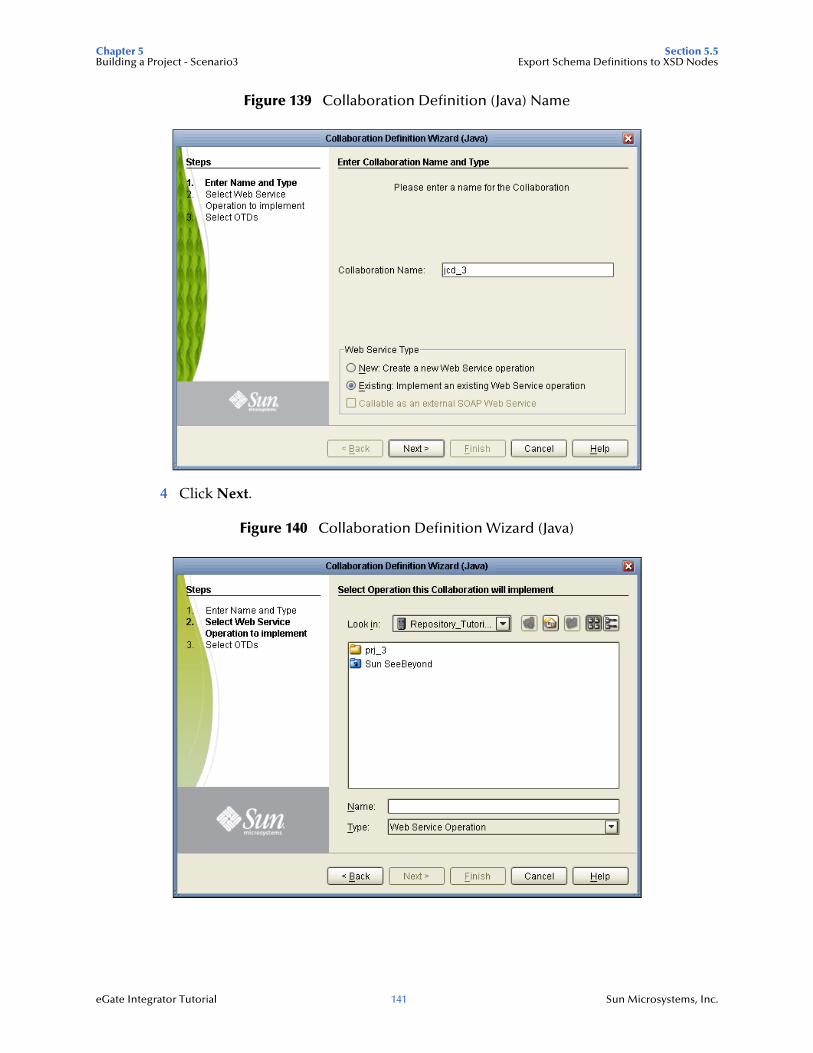
Chapter 5 Section 5.5Building a Project - Scenario3 Export Schema Definitions to XSD Nodes
eGate Integrator Tutorial 141 Sun Microsystems, Inc.
Figure 139 Collaboration Definition (Java) Name
4 Click Next.
Figure 140 Collaboration Definition Wizard (Java)
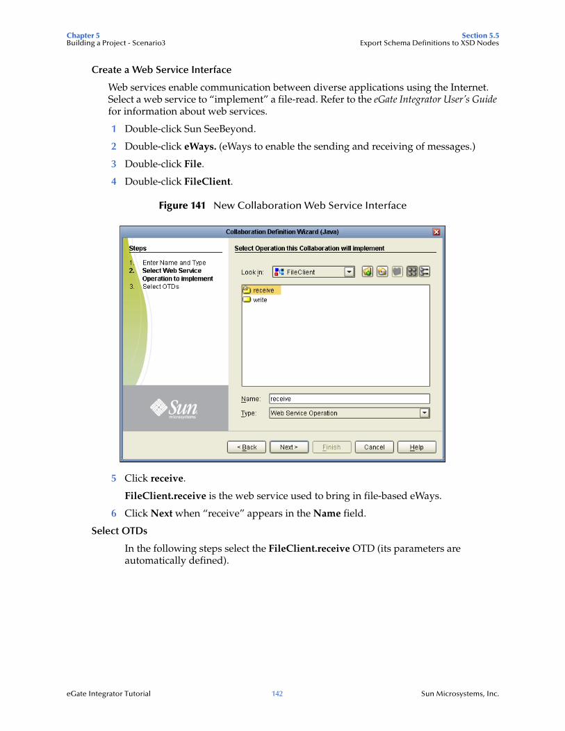
Chapter 5 Section 5.5Building a Project - Scenario3 Export Schema Definitions to XSD Nodes
eGate Integrator Tutorial 142 Sun Microsystems, Inc.
Create a Web Service Interface
Web services enable communication between diverse applications using the Internet. Select a web service to “implement” a file-read. Refer to the eGate Integrator User’s Guide for information about web services.
1 Double-click Sun SeeBeyond.
2 Double-click eWays. (eWays to enable the sending and receiving of messages.)
3 Double-click File.
4 Double-click FileClient.
Figure 141 New Collaboration Web Service Interface
5 Click receive.
FileClient.receive is the web service used to bring in file-based eWays.
6 Click Next when “receive” appears in the Name field.
Select OTDs
In the following steps select the FileClient.receive OTD (its parameters are automatically defined).
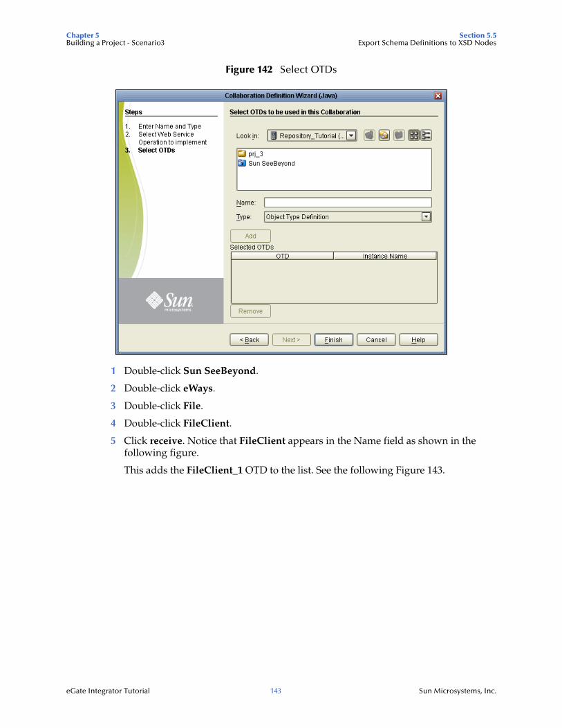
Chapter 5 Section 5.5Building a Project - Scenario3 Export Schema Definitions to XSD Nodes
eGate Integrator Tutorial 143 Sun Microsystems, Inc.
Figure 142 Select OTDs
1 Double-click Sun SeeBeyond.
2 Double-click eWays.
3 Double-click File.
4 Double-click FileClient.
5 Click receive. Notice that FileClient appears in the Name field as shown in the following figure.
This adds the FileClient_1 OTD to the list. See the following Figure 143.
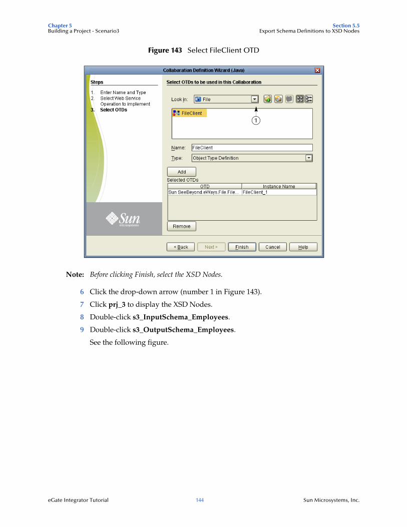
Chapter 5 Section 5.5Building a Project - Scenario3 Export Schema Definitions to XSD Nodes
eGate Integrator Tutorial 144 Sun Microsystems, Inc.
Figure 143 Select FileClient OTD
Note: Before clicking Finish, select the XSD Nodes.
6 Click the drop-down arrow (number 1 in Figure 143).
7 Click prj_3 to display the XSD Nodes.
8 Double-click s3_InputSchema_Employees.
9 Double-click s3_OutputSchema_Employees.
See the following figure.
1

Chapter 5 Section 5.5Building a Project - Scenario3 Export Schema Definitions to XSD Nodes
eGate Integrator Tutorial 145 Sun Microsystems, Inc.
Figure 144 Selected OTDs
All three objects appear in the list of OTDs.
10 Click Finish.
The Collaboration Editor (Java) appears. See the following figure.
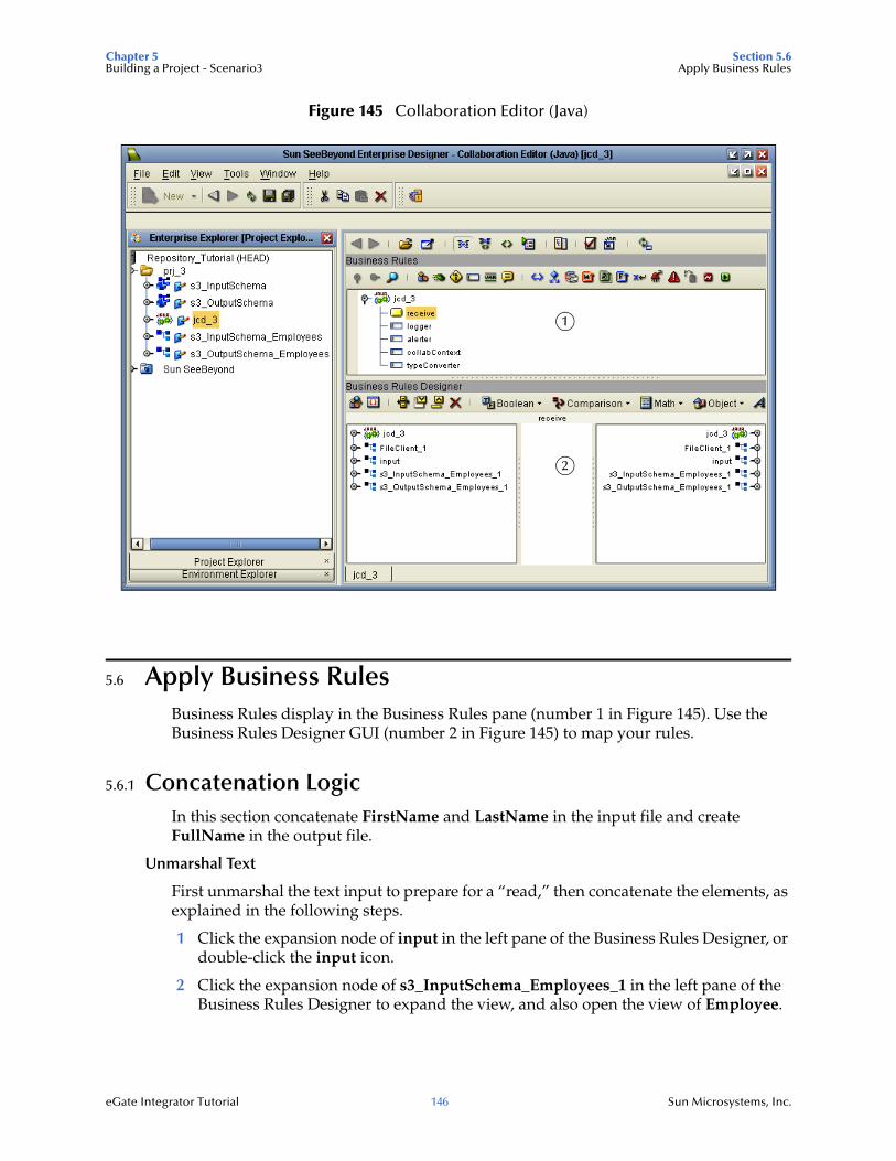
Chapter 5 Section 5.6Building a Project - Scenario3 Apply Business Rules
eGate Integrator Tutorial 146 Sun Microsystems, Inc.
Figure 145 Collaboration Editor (Java)
5.6 Apply Business RulesBusiness Rules display in the Business Rules pane (number 1 in Figure 145). Use the Business Rules Designer GUI (number 2 in Figure 145) to map your rules.
5.6.1 Concatenation LogicIn this section concatenate FirstName and LastName in the input file and create FullName in the output file.
Unmarshal Text
First unmarshal the text input to prepare for a “read,” then concatenate the elements, as explained in the following steps.
1 Click the expansion node of input in the left pane of the Business Rules Designer, or double-click the input icon.
2 Click the expansion node of s3_InputSchema_Employees_1 in the left pane of the Business Rules Designer to expand the view, and also open the view of Employee.
1
2
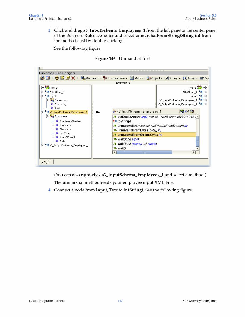
Chapter 5 Section 5.6Building a Project - Scenario3 Apply Business Rules
eGate Integrator Tutorial 147 Sun Microsystems, Inc.
3 Click and drag s3_InputSchema_Employees_1 from the left pane to the center pane of the Business Rules Designer and select unmarshalFromString(String in) from the methods list by double-clicking.
See the following figure.
Figure 146 Unmarshal Text
(You can also right-click s3_InputSchema_Employees_1 and select a method.)
The unmarshal method reads your employee input XML File.
4 Connect a node from input, Text to in(String). See the following figure.
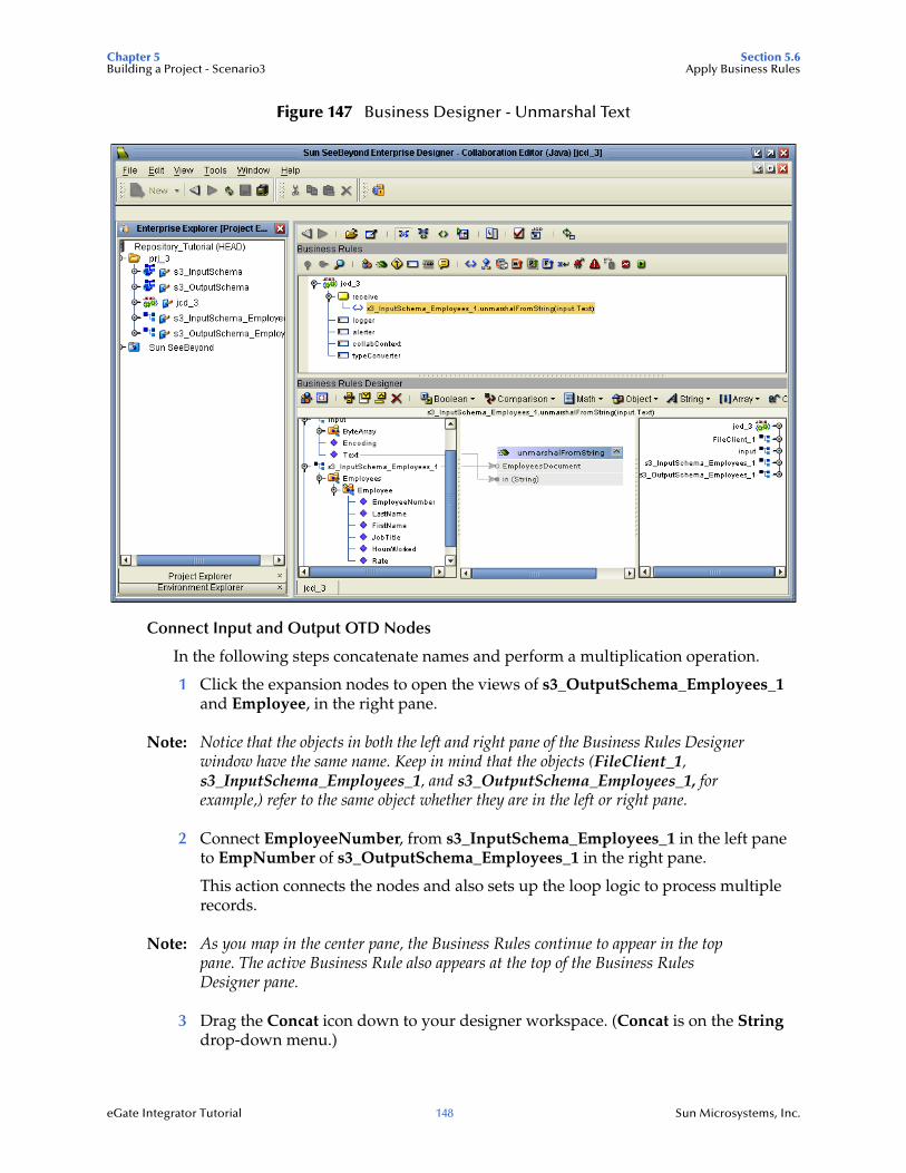
Chapter 5 Section 5.6Building a Project - Scenario3 Apply Business Rules
eGate Integrator Tutorial 148 Sun Microsystems, Inc.
Figure 147 Business Designer - Unmarshal Text
Connect Input and Output OTD Nodes
In the following steps concatenate names and perform a multiplication operation.
1 Click the expansion nodes to open the views of s3_OutputSchema_Employees_1 and Employee, in the right pane.
Note: Notice that the objects in both the left and right pane of the Business Rules Designer window have the same name. Keep in mind that the objects (FileClient_1, s3_InputSchema_Employees_1, and s3_OutputSchema_Employees_1, for example,) refer to the same object whether they are in the left or right pane.
2 Connect EmployeeNumber, from s3_InputSchema_Employees_1 in the left pane to EmpNumber of s3_OutputSchema_Employees_1 in the right pane.
This action connects the nodes and also sets up the loop logic to process multiple records.
Note: As you map in the center pane, the Business Rules continue to appear in the top pane. The active Business Rule also appears at the top of the Business Rules Designer pane.
3 Drag the Concat icon down to your designer workspace. (Concat is on the String drop-down menu.)
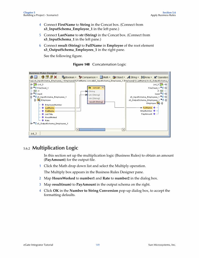
Chapter 5 Section 5.6Building a Project - Scenario3 Apply Business Rules
eGate Integrator Tutorial 149 Sun Microsystems, Inc.
4 Connect FirstName to String in the Concat box. (Connect from s3_InputSchema_Employee_1 in the left pane.)
5 Connect LastName to str (String) in the Concat box. (Connect from s3_InputSchema_1 in the left pane.)
6 Connect result (String) to FullName in Employee of the root element s3_OutputSchema_Employees_1 in the right pane.
See the following figure.
Figure 148 Concatenation Logic
5.6.2 Multiplication LogicIn this section set up the multiplication logic (Business Rules) to obtain an amount (PayAmount) for the output file.
1 Click the Math drop down list and select the Multiply operation.
The Multiply box appears in the Business Rules Designer pane.
2 Map HoursWorked to number1 and Rate to number2 in the dialog box.
3 Map result(num) to PayAmount in the output schema on the right.
4 Click OK in the Number to String Conversion pop-up dialog box, to accept the formatting defaults.
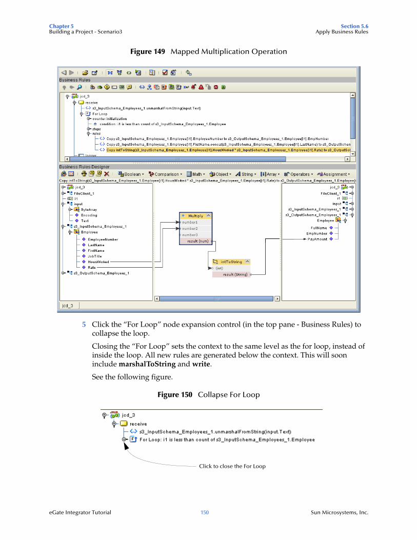
Chapter 5 Section 5.6Building a Project - Scenario3 Apply Business Rules
eGate Integrator Tutorial 150 Sun Microsystems, Inc.
Figure 149 Mapped Multiplication Operation
5 Click the “For Loop” node expansion control (in the top pane - Business Rules) to collapse the loop.
Closing the “For Loop” sets the context to the same level as the for loop, instead of inside the loop. All new rules are generated below the context. This will soon include marshalToString and write.
See the following figure.
Figure 150 Collapse For Loop
Click to close the For Loop
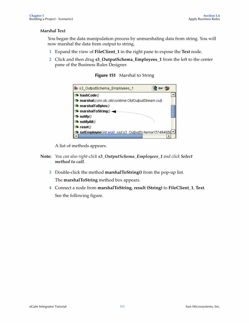
Chapter 5 Section 5.6Building a Project - Scenario3 Apply Business Rules
eGate Integrator Tutorial 151 Sun Microsystems, Inc.
Marshal Text
You began the data manipulation process by unmarshaling data from string. You will now marshal the data from output to string.
1 Expand the view of FileClient_1 in the right pane to expose the Text node.
2 Click and then drag s3_OutputSchema_Employees_1 from the left to the center pane of the Business Rules Designer.
Figure 151 Marshal to String
A list of methods appears.
Note: You can also right-click s3_OutputSchema_Employees_1 and click Select method to call.
3 Double-click the method marshalToString() from the pop-up list.
The marshalToString method box appears.
4 Connect a node from marshalToString, result (String) to FileClient_1, Text.
See the following figure.
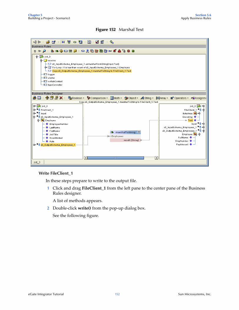
Chapter 5 Section 5.6Building a Project - Scenario3 Apply Business Rules
eGate Integrator Tutorial 152 Sun Microsystems, Inc.
Figure 152 Marshal Text
Write FileClient_1
In these steps prepare to write to the output file.
1 Click and drag FileClient_1 from the left pane to the center pane of the Business Rules designer.
A list of methods appears.
2 Double-click write() from the pop-up dialog box.
See the following figure.
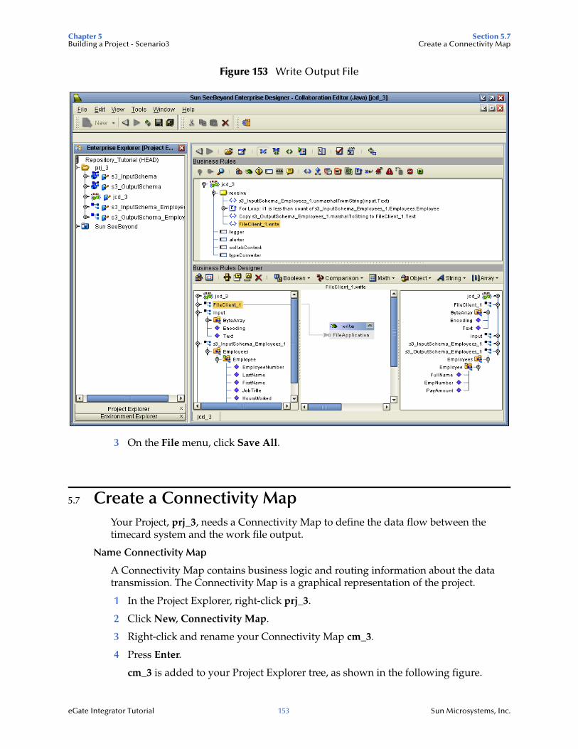
Chapter 5 Section 5.7Building a Project - Scenario3 Create a Connectivity Map
eGate Integrator Tutorial 153 Sun Microsystems, Inc.
Figure 153 Write Output File
3 On the File menu, click Save All.
5.7 Create a Connectivity MapYour Project, prj_3, needs a Connectivity Map to define the data flow between the timecard system and the work file output.
Name Connectivity Map
A Connectivity Map contains business logic and routing information about the data transmission. The Connectivity Map is a graphical representation of the project.
1 In the Project Explorer, right-click prj_3.
2 Click New, Connectivity Map.
3 Right-click and rename your Connectivity Map cm_3.
4 Press Enter.
cm_3 is added to your Project Explorer tree, as shown in the following figure.
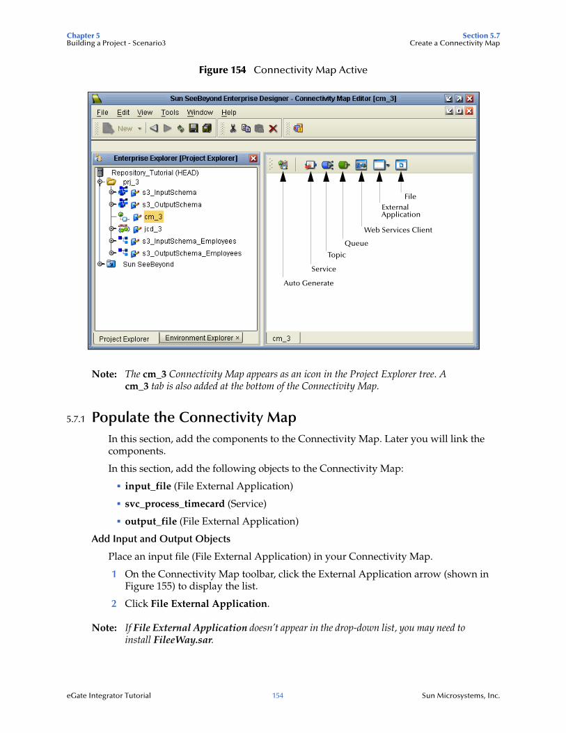
Chapter 5 Section 5.7Building a Project - Scenario3 Create a Connectivity Map
eGate Integrator Tutorial 154 Sun Microsystems, Inc.
Figure 154 Connectivity Map Active
Note: The cm_3 Connectivity Map appears as an icon in the Project Explorer tree. A cm_3 tab is also added at the bottom of the Connectivity Map.
5.7.1 Populate the Connectivity MapIn this section, add the components to the Connectivity Map. Later you will link the components.
In this section, add the following objects to the Connectivity Map:
input_file (File External Application)
svc_process_timecard (Service)
output_file (File External Application)
Add Input and Output Objects
Place an input file (File External Application) in your Connectivity Map.
1 On the Connectivity Map toolbar, click the External Application arrow (shown in Figure 155) to display the list.
2 Click File External Application.
Note: If File External Application doesn’t appear in the drop-down list, you may need to install FileeWay.sar.
External
Queue
Topic
Web Services Client
Service
Auto Generate
Application
File
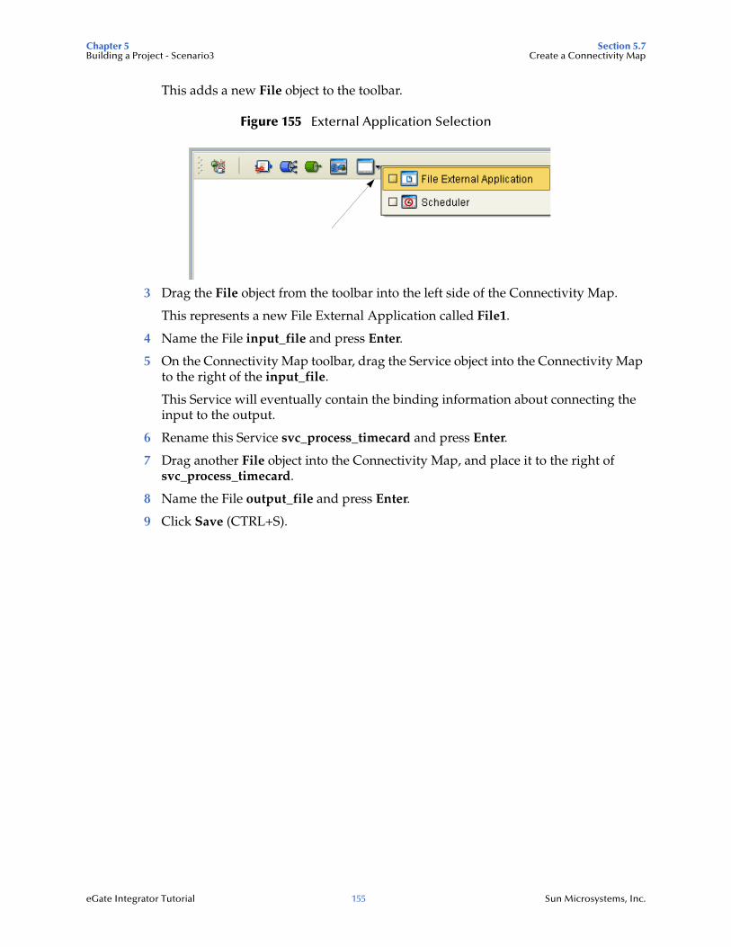
Chapter 5 Section 5.7Building a Project - Scenario3 Create a Connectivity Map
eGate Integrator Tutorial 155 Sun Microsystems, Inc.
This adds a new File object to the toolbar.
Figure 155 External Application Selection
3 Drag the File object from the toolbar into the left side of the Connectivity Map.
This represents a new File External Application called File1.
4 Name the File input_file and press Enter.
5 On the Connectivity Map toolbar, drag the Service object into the Connectivity Map to the right of the input_file.
This Service will eventually contain the binding information about connecting the input to the output.
6 Rename this Service svc_process_timecard and press Enter.
7 Drag another File object into the Connectivity Map, and place it to the right of svc_process_timecard.
8 Name the File output_file and press Enter.
9 Click Save (CTRL+S).
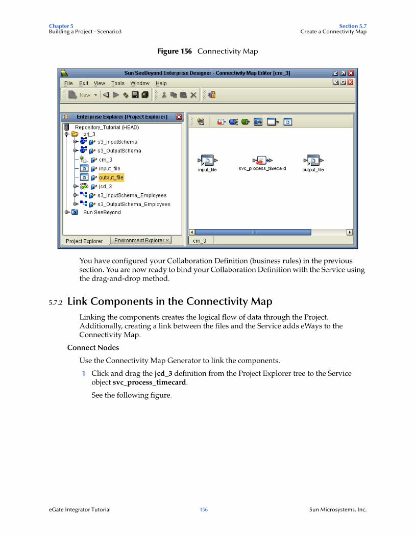
Chapter 5 Section 5.7Building a Project - Scenario3 Create a Connectivity Map
eGate Integrator Tutorial 156 Sun Microsystems, Inc.
Figure 156 Connectivity Map
You have configured your Collaboration Definition (business rules) in the previous section. You are now ready to bind your Collaboration Definition with the Service using the drag-and-drop method.
5.7.2 Link Components in the Connectivity MapLinking the components creates the logical flow of data through the Project. Additionally, creating a link between the files and the Service adds eWays to the Connectivity Map.
Connect Nodes
Use the Connectivity Map Generator to link the components.
1 Click and drag the jcd_3 definition from the Project Explorer tree to the Service object svc_process_timecard.
See the following figure.
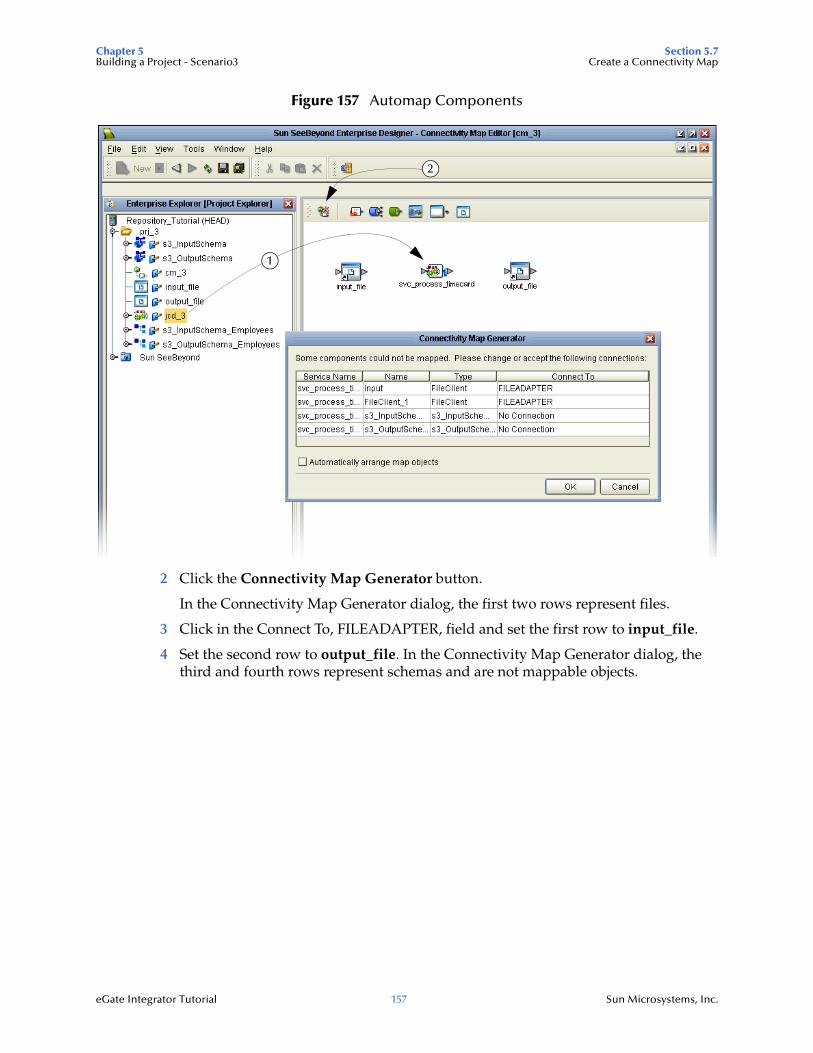
Chapter 5 Section 5.7Building a Project - Scenario3 Create a Connectivity Map
eGate Integrator Tutorial 157 Sun Microsystems, Inc.
Figure 157 Automap Components
2 Click the Connectivity Map Generator button.
In the Connectivity Map Generator dialog, the first two rows represent files.
3 Click in the Connect To, FILEADAPTER, field and set the first row to input_file.
4 Set the second row to output_file. In the Connectivity Map Generator dialog, the third and fourth rows represent schemas and are not mappable objects.
1
2
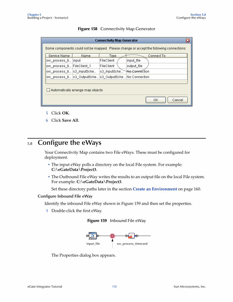
Chapter 5 Section 5.8Building a Project - Scenario3 Configure the eWays
eGate Integrator Tutorial 158 Sun Microsystems, Inc.
Figure 158 Connectivity Map Generator
5 Click OK.
6 Click Save All.
5.8 Configure the eWaysYour Connectivity Map contains two File eWays. These must be configured for deployment.
The input eWay polls a directory on the local File system. For example: C:\eGateData\Project3.
The Outbound File eWay writes the results to an output file on the local File system. For example: C:\eGateData\Project3.
Set these directory paths later in the section Create an Environment on page 160.
Configure Inbound File eWay
Identify the inbound File eWay shown in Figure 159 and then set the properties.
1 Double-click the first eWay.
Figure 159 Inbound File eWay
The Properties dialog box appears.
input_file svc_process_timecard
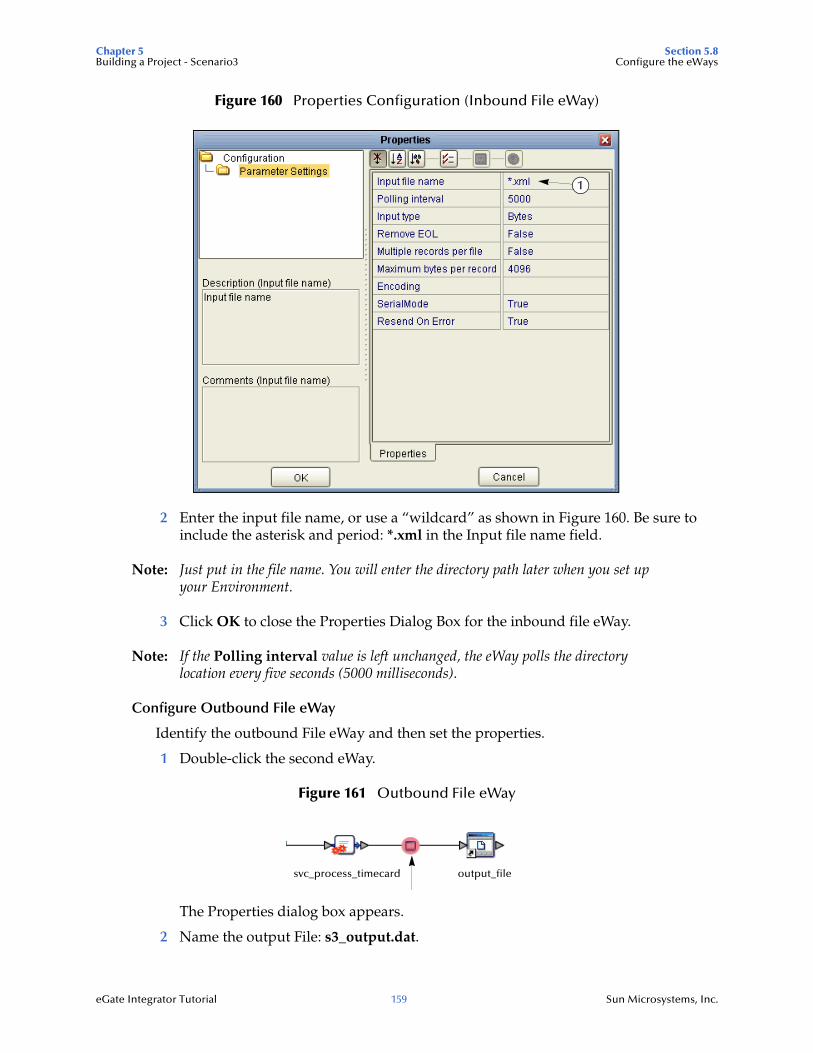
Chapter 5 Section 5.8Building a Project - Scenario3 Configure the eWays
eGate Integrator Tutorial 159 Sun Microsystems, Inc.
Figure 160 Properties Configuration (Inbound File eWay)
2 Enter the input file name, or use a “wildcard” as shown in Figure 160. Be sure to include the asterisk and period: *.xml in the Input file name field.
Note: Just put in the file name. You will enter the directory path later when you set up your Environment.
3 Click OK to close the Properties Dialog Box for the inbound file eWay.
Note: If the Polling interval value is left unchanged, the eWay polls the directory location every five seconds (5000 milliseconds).
Configure Outbound File eWay
Identify the outbound File eWay and then set the properties.
1 Double-click the second eWay.
Figure 161 Outbound File eWay
The Properties dialog box appears.
2 Name the output File: s3_output.dat.
1
svc_process_timecard output_file
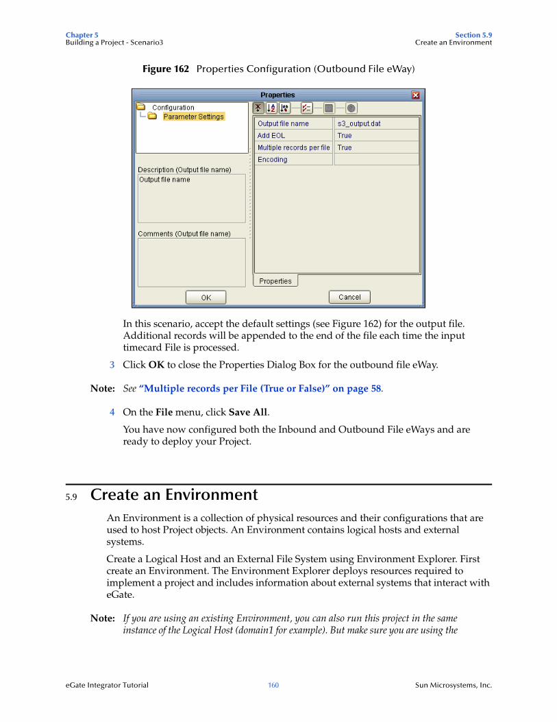
Chapter 5 Section 5.9Building a Project - Scenario3 Create an Environment
eGate Integrator Tutorial 160 Sun Microsystems, Inc.
Figure 162 Properties Configuration (Outbound File eWay)
In this scenario, accept the default settings (see Figure 162) for the output file. Additional records will be appended to the end of the file each time the input timecard File is processed.
3 Click OK to close the Properties Dialog Box for the outbound file eWay.
Note: See “Multiple records per File (True or False)” on page 58.
4 On the File menu, click Save All.
You have now configured both the Inbound and Outbound File eWays and are ready to deploy your Project.
5.9 Create an EnvironmentAn Environment is a collection of physical resources and their configurations that are used to host Project objects. An Environment contains logical hosts and external systems.
Create a Logical Host and an External File System using Environment Explorer. First create an Environment. The Environment Explorer deploys resources required to implement a project and includes information about external systems that interact with eGate.
Note: If you are using an existing Environment, you can also run this project in the same instance of the Logical Host (domain1 for example). But make sure you are using the
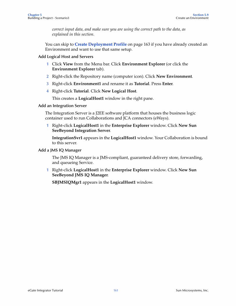
Chapter 5 Section 5.9Building a Project - Scenario3 Create an Environment
eGate Integrator Tutorial 161 Sun Microsystems, Inc.
correct input data, and make sure you are using the correct path to the data, as explained in this section.
You can skip to Create Deployment Profile on page 163 if you have already created an Environment and want to use that same setup.
Add Logical Host and Servers
1 Click View from the Menu bar. Click Environment Explorer (or click the Environment Explorer tab).
2 Right-click the Repository name (computer icon). Click New Environment.
3 Right-click Environment1 and rename it as Tutorial. Press Enter.
4 Right-click Tutorial. Click New Logical Host.
This creates a LogicalHost1 window in the right pane.
Add an Integration Server
The Integration Server is a J2EE software platform that houses the business logic container used to run Collaborations and JCA connectors (eWays).
1 Right-click LogicalHost1 in the Enterprise Explorer window. Click New Sun SeeBeyond Integration Server.
IntegrationSvr1 appears in the LogicalHost1 window. Your Collaboration is bound to this server.
Add a JMS IQ Manager
The JMS IQ Manager is a JMS-compliant, guaranteed delivery store, forwarding, and queueing Service.
1 Right-click LogicalHost1 in the Enterprise Explorer window. Click New Sun SeeBeyond JMS IQ Manager.
SBJMSIQMgr1 appears in the LogicalHost1 window.
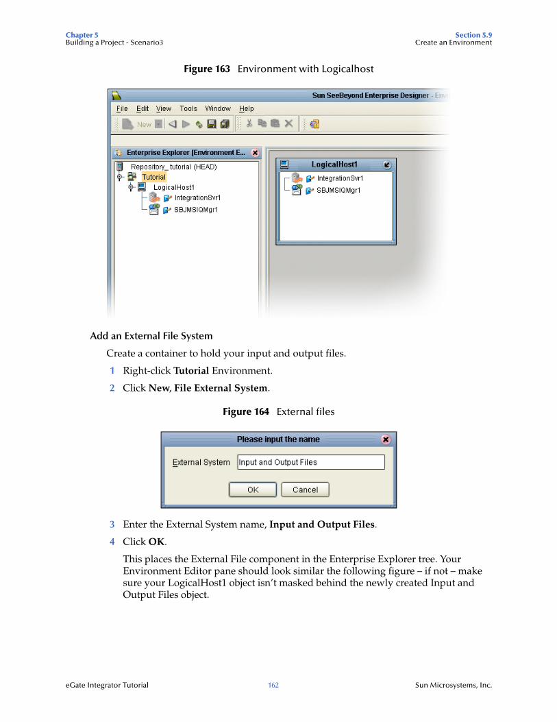
Chapter 5 Section 5.9Building a Project - Scenario3 Create an Environment
eGate Integrator Tutorial 162 Sun Microsystems, Inc.
Figure 163 Environment with Logicalhost
Add an External File System
Create a container to hold your input and output files.
1 Right-click Tutorial Environment.
2 Click New, File External System.
Figure 164 External files
3 Enter the External System name, Input and Output Files.
4 Click OK.
This places the External File component in the Enterprise Explorer tree. Your Environment Editor pane should look similar the following figure – if not – make sure your LogicalHost1 object isn’t masked behind the newly created Input and Output Files object.
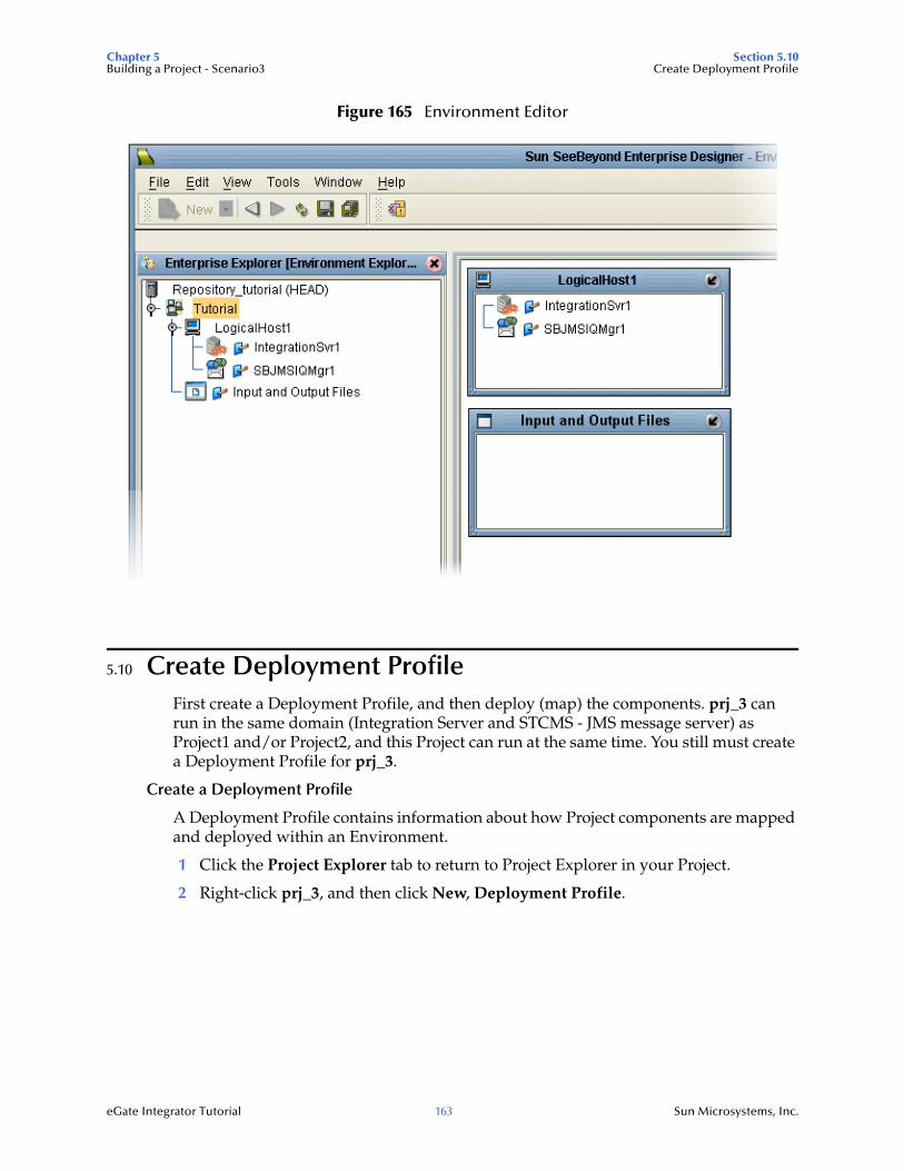
Chapter 5 Section 5.10Building a Project - Scenario3 Create Deployment Profile
eGate Integrator Tutorial 163 Sun Microsystems, Inc.
Figure 165 Environment Editor
5.10 Create Deployment ProfileFirst create a Deployment Profile, and then deploy (map) the components. prj_3 can run in the same domain (Integration Server and STCMS - JMS message server) as Project1 and/or Project2, and this Project can run at the same time. You still must create a Deployment Profile for prj_3.
Create a Deployment Profile
A Deployment Profile contains information about how Project components are mapped and deployed within an Environment.
1 Click the Project Explorer tab to return to Project Explorer in your Project.
2 Right-click prj_3, and then click New, Deployment Profile.
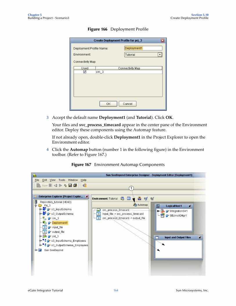
Chapter 5 Section 5.10Building a Project - Scenario3 Create Deployment Profile
eGate Integrator Tutorial 164 Sun Microsystems, Inc.
Figure 166 Deployment Profile
3 Accept the default name Deployment1 (and Tutorial). Click OK.
Your files and svc_process_timecard appear in the center pane of the Environment editor. Deploy these components using the Automap feature.
If not already open, double-click Deployment1 in the Project Explorer to open the Environment editor.
4 Click the Automap button (number 1 in the following figure) in the Environment toolbar. (Refer to Figure 167.)
Figure 167 Environment Automap Components
1

Chapter 5 Section 5.11Building a Project - Scenario3 Build and Deploy the Project
eGate Integrator Tutorial 165 Sun Microsystems, Inc.
The center pane of the Environment Editor should be empty after all the available objects and components have been mapped to the Environment. You are now ready to build and deploy your Project.
5 Save your Project.
5.11 Build and Deploy the ProjectMake sure an instance of the Logical Host is running (domain) before you deploy your project. You can start the domain with the domainmgr.bat script that is located in your, logicalhost directory.
Enter Passwords
Make sure you have entered your user name and password (see the steps below) for the Integration Server (and the JMS IQ Manager), and make sure your domain (Integration Server and STCMS - JMS server) is running.
Integration Server Password
Enter a password and verify the URL port for the Integration Server.
1 Click the Environment Explorer tab.
2 Right-click IntegrationSvr1 in the Environment Explorer tree.
3 Click Properties.
4 Enter and confirm Password.
5 Verify the Integration Server URL, Admin port.
See the following figure.
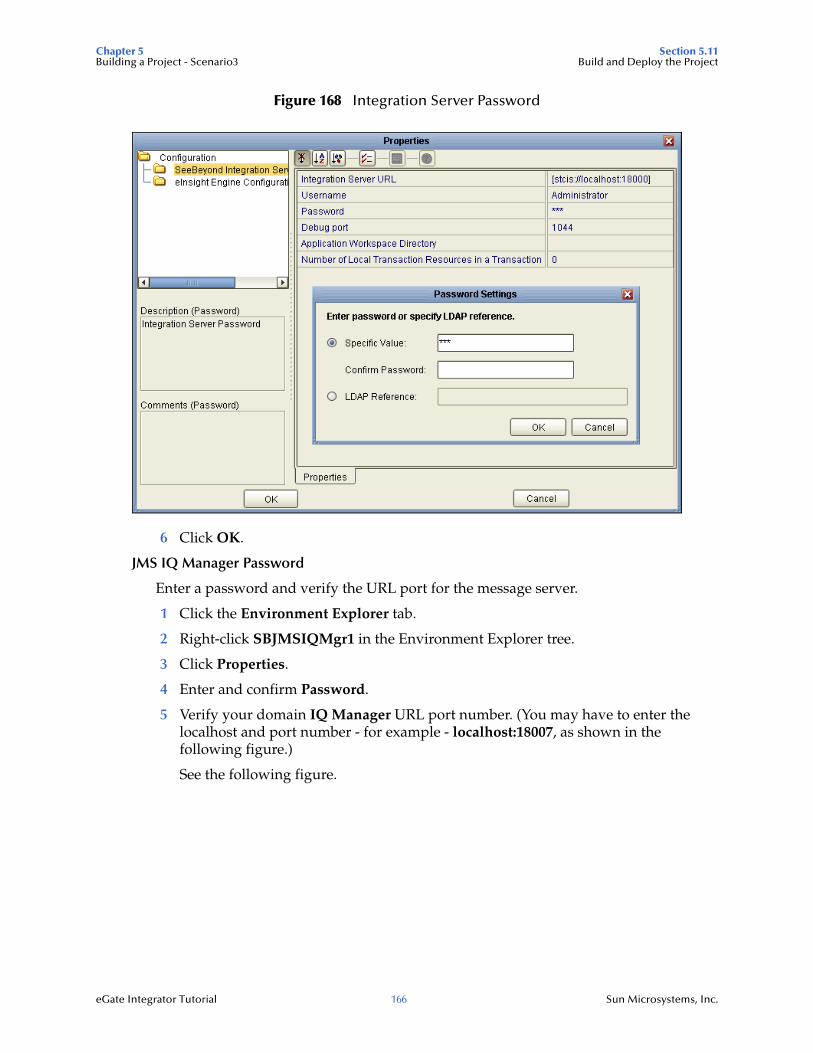
Chapter 5 Section 5.11Building a Project - Scenario3 Build and Deploy the Project
eGate Integrator Tutorial 166 Sun Microsystems, Inc.
Figure 168 Integration Server Password
6 Click OK.
JMS IQ Manager Password
Enter a password and verify the URL port for the message server.
1 Click the Environment Explorer tab.
2 Right-click SBJMSIQMgr1 in the Environment Explorer tree.
3 Click Properties.
4 Enter and confirm Password.
5 Verify your domain IQ Manager URL port number. (You may have to enter the localhost and port number - for example - localhost:18007, as shown in the following figure.)
See the following figure.
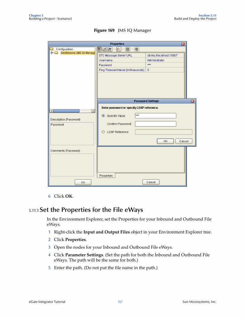
Chapter 5 Section 5.11Building a Project - Scenario3 Build and Deploy the Project
eGate Integrator Tutorial 167 Sun Microsystems, Inc.
Figure 169 JMS IQ Manager
6 Click OK.
5.11.1 Set the Properties for the File eWaysIn the Environment Explorer, set the Properties for your Inbound and Outbound File eWays.
1 Right-click the Input and Output Files object in your Environment Explorer tree.
2 Click Properties.
3 Open the nodes for your Inbound and Outbound File eWays.
4 Click Parameter Settings. (Set the path for both the Inbound and Outbound File eWays. The path will be the same for both.)
5 Enter the path. (Do not put the file name in the path.)
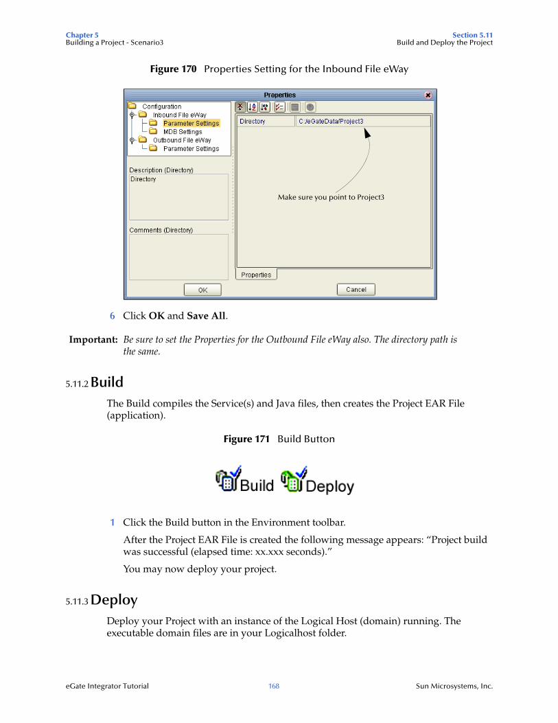
Chapter 5 Section 5.11Building a Project - Scenario3 Build and Deploy the Project
eGate Integrator Tutorial 168 Sun Microsystems, Inc.
Figure 170 Properties Setting for the Inbound File eWay
6 Click OK and Save All.
Important: Be sure to set the Properties for the Outbound File eWay also. The directory path is the same.
5.11.2 BuildThe Build compiles the Service(s) and Java files, then creates the Project EAR File (application).
Figure 171 Build Button
1 Click the Build button in the Environment toolbar.
After the Project EAR File is created the following message appears: “Project build was successful (elapsed time: xx.xxx seconds).”
You may now deploy your project.
5.11.3 DeployDeploy your Project with an instance of the Logical Host (domain) running. The executable domain files are in your Logicalhost folder.
Make sure you point to Project3
Chapter 5 Section 5.12Building a Project - Scenario3 Verify Output Data
eGate Integrator Tutorial 169 Sun Microsystems, Inc.
Figure 172 Deploy Button
1 Click the Deploy button.
2 Click Yes when you see the message “Are you sure you want to deploy the current project deployment?”
A message displays: “Deploying the application...”
You will receive a message similar to the following figure when the deployment is successful.
Figure 173 Deployment Successful
3 Click OK.
Your Project (application) has been deployed.
5.12 Verify Output DataThe Management Agent processes your input File, s3_TimeCard.xml, and writes the results to s3_output.dat.
View Output
Use Windows Explorer to navigate to C:\eGateData\Project3.
See that the Inbound File eWay, after processing the inbound file, renamed the file to s3_TimeCard.xml~in. You can make changes in this file using a text editor and then rename the file back to s3_TimeCard.xml and immediately see the results of your changes after the file is processed again.
See that the Output eWay generated the output File, s3_output.dat.
Use Notepad or a similar text editor to view the contents of the output file.
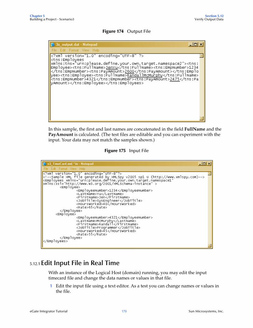
Chapter 5 Section 5.12Building a Project - Scenario3 Verify Output Data
eGate Integrator Tutorial 170 Sun Microsystems, Inc.
Figure 174 Output File
In this sample, the first and last names are concatenated in the field FullName and the PayAmount is calculated. (The test files are editable and you can experiment with the input. Your data may not match the samples shown.)
Figure 175 Input File
5.12.1 Edit Input File in Real TimeWith an instance of the Logical Host (domain) running, you may edit the input timecard file and change the data names or values in that file.
1 Edit the input file using a text editor. As a test you can change names or values in the file.

Chapter 5 Section 5.12Building a Project - Scenario3 Verify Output Data
eGate Integrator Tutorial 171 Sun Microsystems, Inc.
2 Rename the input file from s3_TimeCard.xml.~in. to s3_TimeCard.xml. Delete the file extension name ~in.
Within a few seconds the File eWay processes the input file again and writes the results to s3_output.dat.
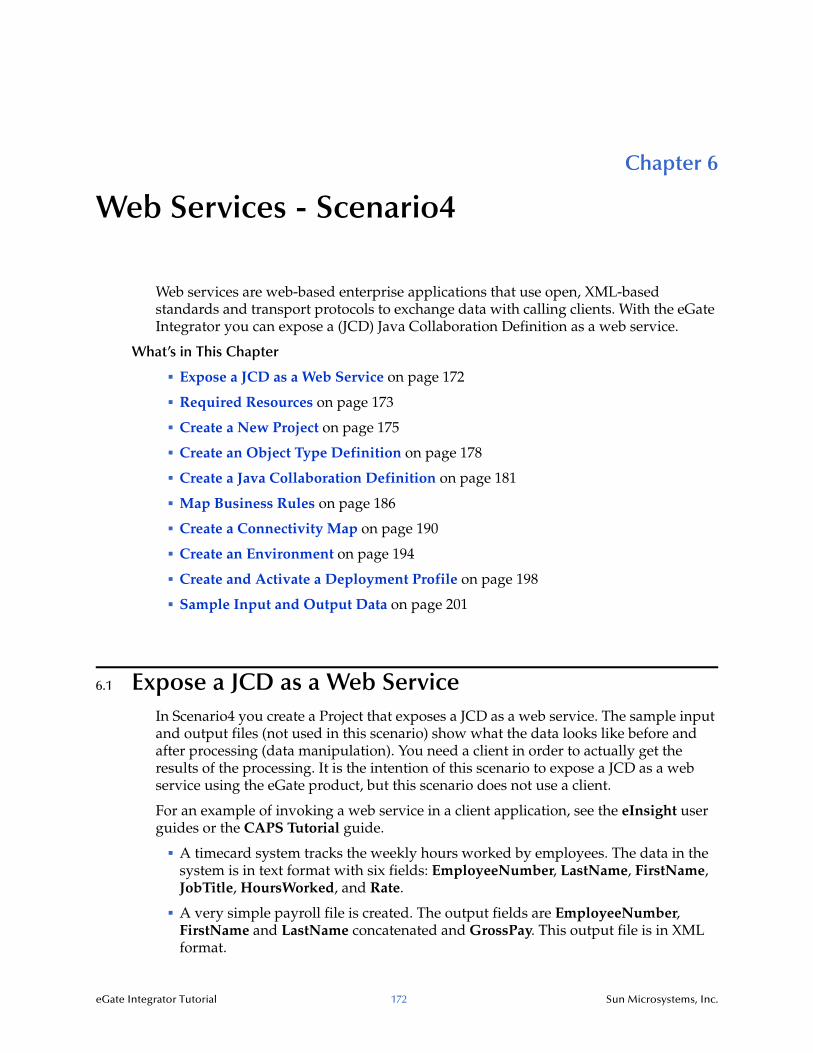
eGate Integrator Tutorial 172 Sun Microsystems, Inc.
Chapter 6
Web Services - Scenario4
Web services are web-based enterprise applications that use open, XML-based standards and transport protocols to exchange data with calling clients. With the eGate Integrator you can expose a (JCD) Java Collaboration Definition as a web service.
What’s in This Chapter
Expose a JCD as a Web Service on page 172
Required Resources on page 173
Create a New Project on page 175
Create an Object Type Definition on page 178
Create a Java Collaboration Definition on page 181
Map Business Rules on page 186
Create a Connectivity Map on page 190
Create an Environment on page 194
Create and Activate a Deployment Profile on page 198
Sample Input and Output Data on page 201
6.1 Expose a JCD as a Web ServiceIn Scenario4 you create a Project that exposes a JCD as a web service. The sample input and output files (not used in this scenario) show what the data looks like before and after processing (data manipulation). You need a client in order to actually get the results of the processing. It is the intention of this scenario to expose a JCD as a web service using the eGate product, but this scenario does not use a client.
For an example of invoking a web service in a client application, see the eInsight user guides or the CAPS Tutorial guide.
A timecard system tracks the weekly hours worked by employees. The data in the system is in text format with six fields: EmployeeNumber, LastName, FirstName, JobTitle, HoursWorked, and Rate.
A very simple payroll file is created. The output fields are EmployeeNumber, FirstName and LastName concatenated and GrossPay. This output file is in XML format.
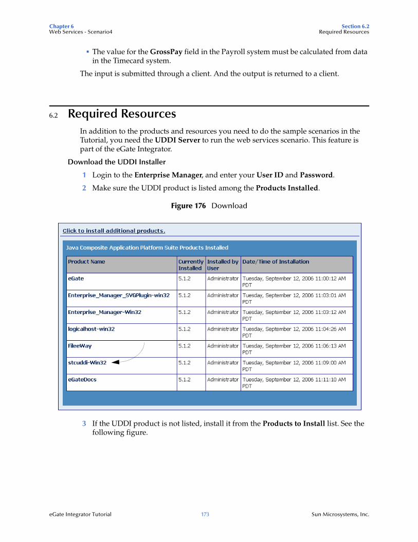
Chapter 6 Section 6.2Web Services - Scenario4 Required Resources
eGate Integrator Tutorial 173 Sun Microsystems, Inc.
The value for the GrossPay field in the Payroll system must be calculated from data in the Timecard system.
The input is submitted through a client. And the output is returned to a client.
6.2 Required ResourcesIn addition to the products and resources you need to do the sample scenarios in the Tutorial, you need the UDDI Server to run the web services scenario. This feature is part of the eGate Integrator.
Download the UDDI Installer
1 Login to the Enterprise Manager, and enter your User ID and Password.
2 Make sure the UDDI product is listed among the Products Installed.
Figure 176 Download
3 If the UDDI product is not listed, install it from the Products to Install list. See the following figure.
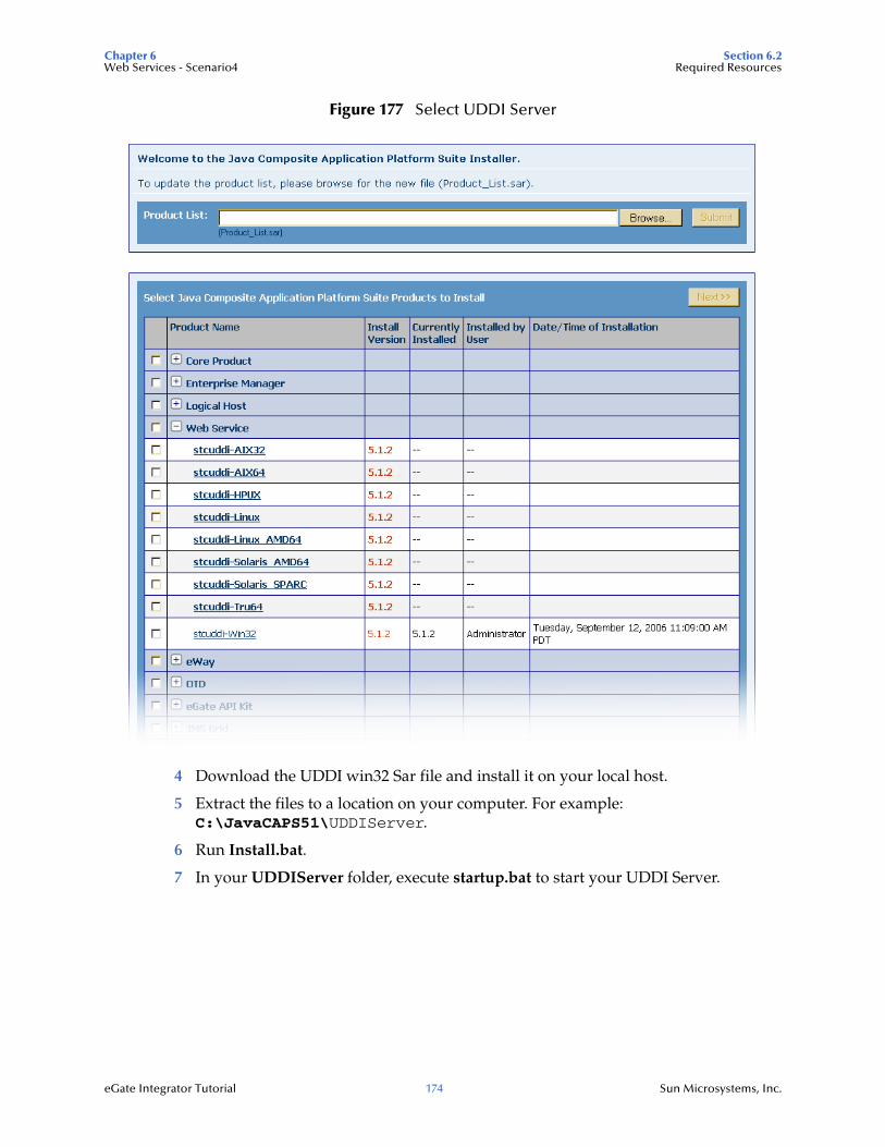
Chapter 6 Section 6.2Web Services - Scenario4 Required Resources
eGate Integrator Tutorial 174 Sun Microsystems, Inc.
Figure 177 Select UDDI Server
4 Download the UDDI win32 Sar file and install it on your local host.
5 Extract the files to a location on your computer. For example: C:\JavaCAPS51\UDDIServer.
6 Run Install.bat.
7 In your UDDIServer folder, execute startup.bat to start your UDDI Server.
Chapter 6 Section 6.3Web Services - Scenario4 Create a New Project
eGate Integrator Tutorial 175 Sun Microsystems, Inc.
6.2.1 Download the Sample FileSee “Download the Sample files” on page 23. The sample files used in the scenario are in the Project4 folder.
Sample Input SchemaInput_Employee.xsd
Sample Output SchemaOutput_Employee.xsd
Sample Input FileInputWS.xml
6.3 Create a New ProjectCreate a new Project to expose a JCD as a web service. Keep in mind that in this scenario you are only “exposing” a JCD as a web service.
Start Enterprise Designer
Start the Enterprise Designer according to your organization’s instructions.
1 Start the Enterprise Designer by executing runed.bat in your JavaCAPS51 folder: C:\JavaCAPS51\edesigner\bin.
The Enterprise Designer Login dialog box appears.
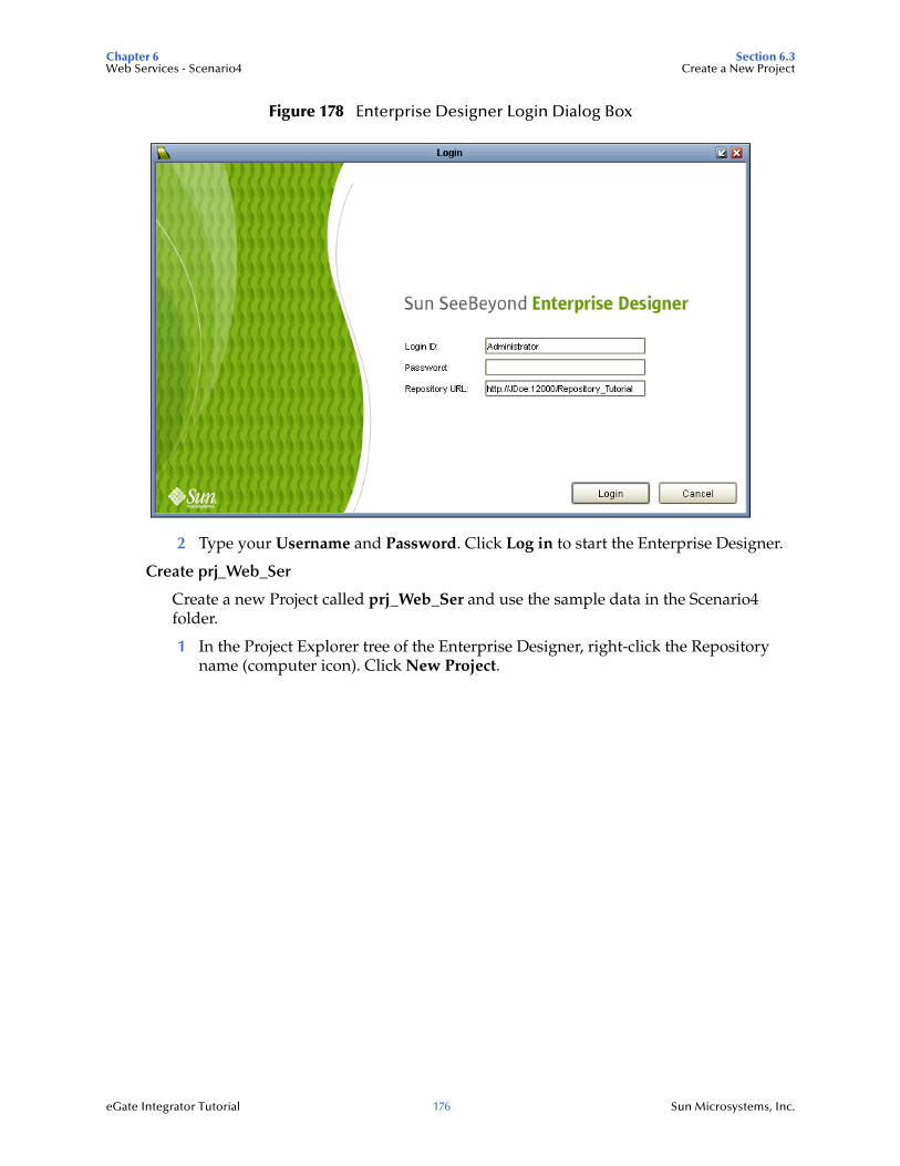
Chapter 6 Section 6.3Web Services - Scenario4 Create a New Project
eGate Integrator Tutorial 176 Sun Microsystems, Inc.
Figure 178 Enterprise Designer Login Dialog Box
2 Type your Username and Password. Click Log in to start the Enterprise Designer.
Create prj_Web_Ser
Create a new Project called prj_Web_Ser and use the sample data in the Scenario4 folder.
1 In the Project Explorer tree of the Enterprise Designer, right-click the Repository name (computer icon). Click New Project.
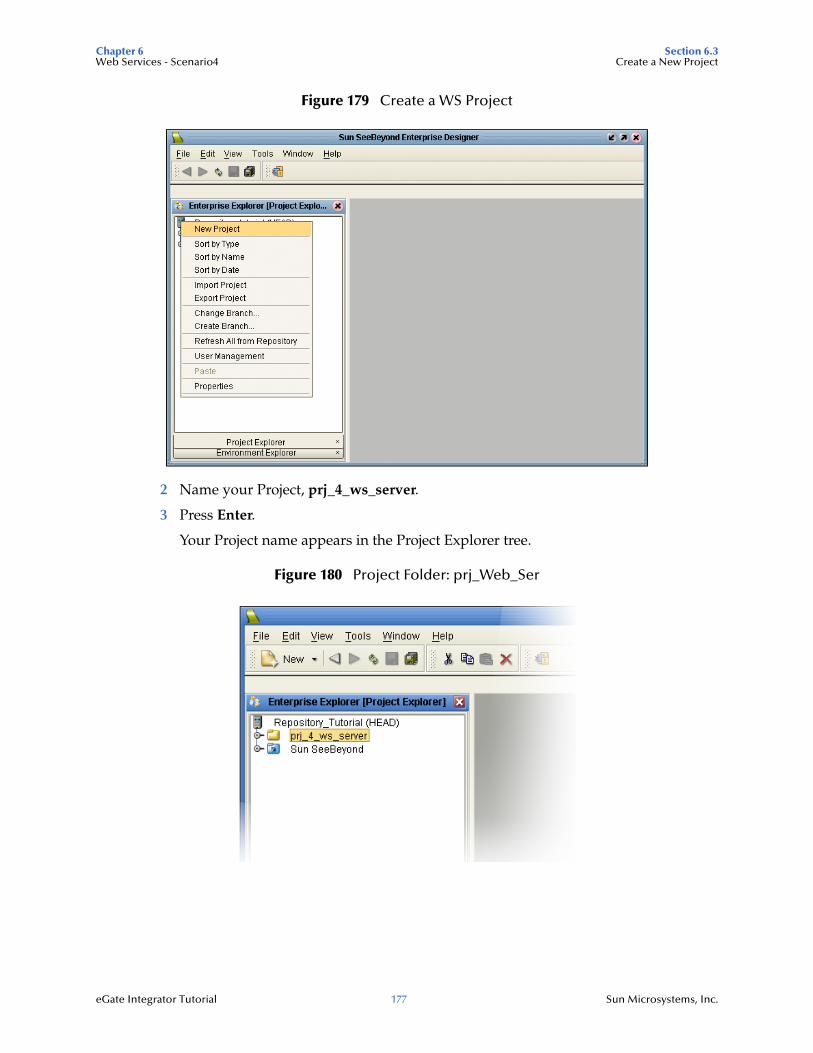
Chapter 6 Section 6.3Web Services - Scenario4 Create a New Project
eGate Integrator Tutorial 177 Sun Microsystems, Inc.
Figure 179 Create a WS Project
2 Name your Project, prj_4_ws_server.
3 Press Enter.
Your Project name appears in the Project Explorer tree.
Figure 180 Project Folder: prj_Web_Ser
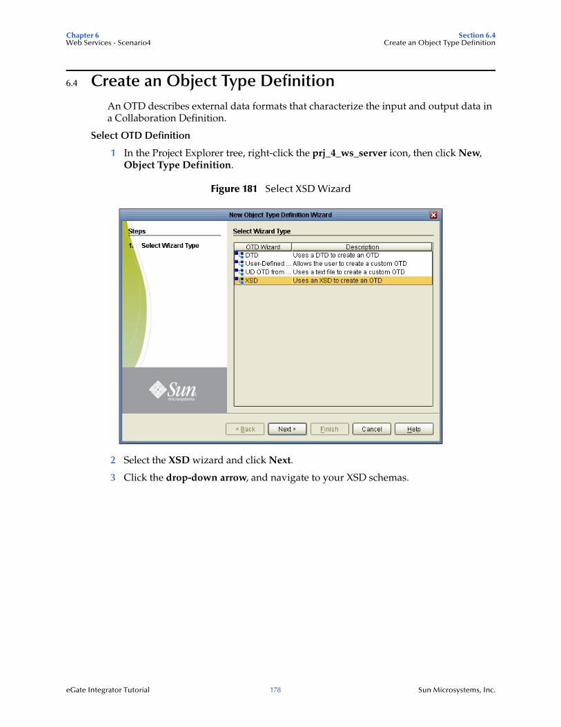
Chapter 6 Section 6.4Web Services - Scenario4 Create an Object Type Definition
eGate Integrator Tutorial 178 Sun Microsystems, Inc.
6.4 Create an Object Type DefinitionAn OTD describes external data formats that characterize the input and output data in a Collaboration Definition.
Select OTD Definition
1 In the Project Explorer tree, right-click the prj_4_ws_server icon, then click New, Object Type Definition.
Figure 181 Select XSD Wizard
2 Select the XSD wizard and click Next.
3 Click the drop-down arrow, and navigate to your XSD schemas.
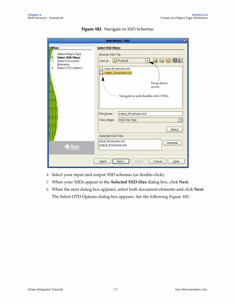
Chapter 6 Section 6.4Web Services - Scenario4 Create an Object Type Definition
eGate Integrator Tutorial 179 Sun Microsystems, Inc.
Figure 182 Navigate to XSD Schemas
4 Select your input and output XSD schemas (or double-click).
5 When your XSDs appear in the Selected XSD files dialog box, click Next.
6 When the next dialog box appears, select both document elements and click Next.
The Select OTD Options dialog box appears. See the following Figure 183.
Drop-downarrow
Navigate to and double-click OTDs
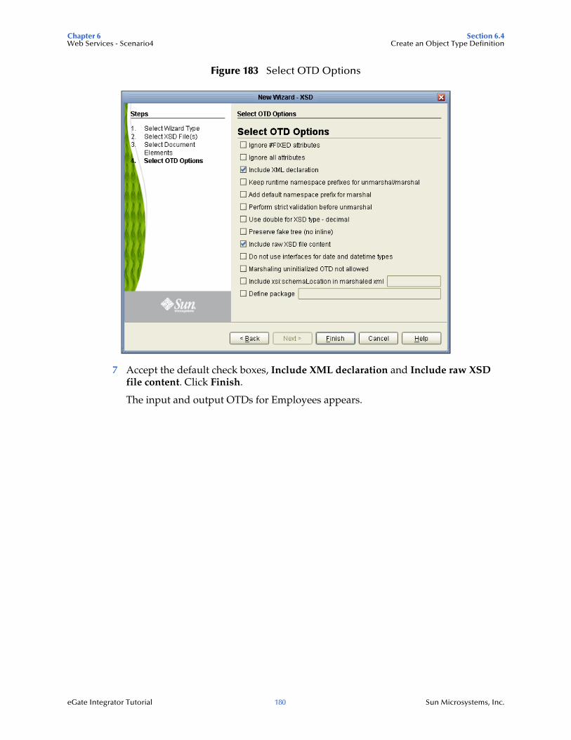
Chapter 6 Section 6.4Web Services - Scenario4 Create an Object Type Definition
eGate Integrator Tutorial 180 Sun Microsystems, Inc.
Figure 183 Select OTD Options
7 Accept the default check boxes, Include XML declaration and Include raw XSD file content. Click Finish.
The input and output OTDs for Employees appears.
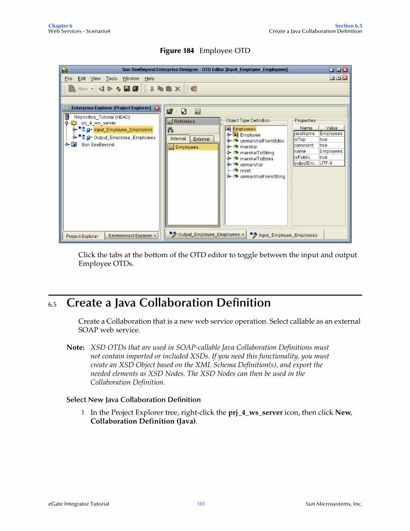
Chapter 6 Section 6.5Web Services - Scenario4 Create a Java Collaboration Definition
eGate Integrator Tutorial 181 Sun Microsystems, Inc.
Figure 184 Employee OTD
Click the tabs at the bottom of the OTD editor to toggle between the input and output Employee OTDs.
6.5 Create a Java Collaboration DefinitionCreate a Collaboration that is a new web service operation. Select callable as an external SOAP web service.
Note: XSD OTDs that are used in SOAP-callable Java Collaboration Definitions must not contain imported or included XSDs. If you need this functionality, you must create an XSD Object based on the XML Schema Definition(s), and export the needed elements as XSD Nodes. The XSD Nodes can then be used in the Collaboration Definition.
Select New Java Collaboration Definition
1 In the Project Explorer tree, right-click the prj_4_ws_server icon, then click New, Collaboration Definition (Java).

Chapter 6 Section 6.5Web Services - Scenario4 Create a Java Collaboration Definition
eGate Integrator Tutorial 182 Sun Microsystems, Inc.
Figure 185 Java Collaboration
The Collaboration Definition Wizard appears.
2 Enter jcd_WS_collab as the Collaboration name.
3 Check the options, as shown in the following figure.
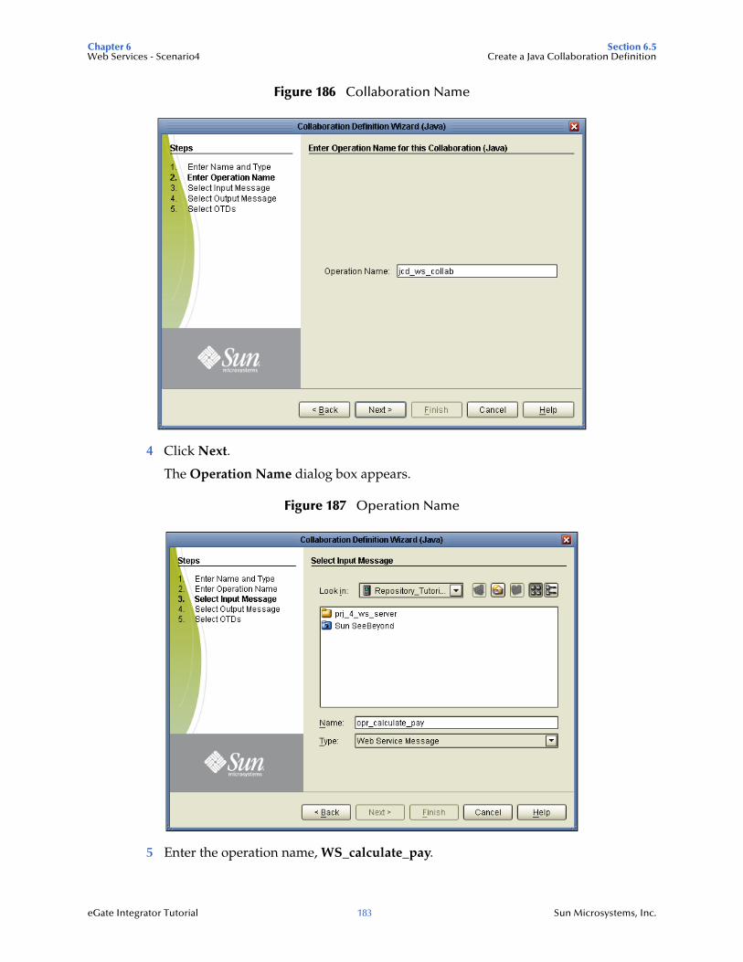
Chapter 6 Section 6.5Web Services - Scenario4 Create a Java Collaboration Definition
eGate Integrator Tutorial 183 Sun Microsystems, Inc.
Figure 186 Collaboration Name
4 Click Next.
The Operation Name dialog box appears.
Figure 187 Operation Name
5 Enter the operation name, WS_calculate_pay.
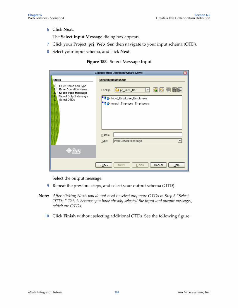
Chapter 6 Section 6.5Web Services - Scenario4 Create a Java Collaboration Definition
eGate Integrator Tutorial 184 Sun Microsystems, Inc.
6 Click Next.
The Select Input Message dialog box appears.
7 Click your Project, prj_Web_Ser, then navigate to your input schema (OTD).
8 Select your input schema, and click Next.
Figure 188 Select Message Input
Select the output message.
9 Repeat the previous steps, and select your output schema (OTD).
Note: After clicking Next, you do not need to select any more OTDs in Step 5 “Select OTDs.” This is because you have already selected the input and output messages, which are OTDs.
10 Click Finish without selecting additional OTDs. See the following figure.
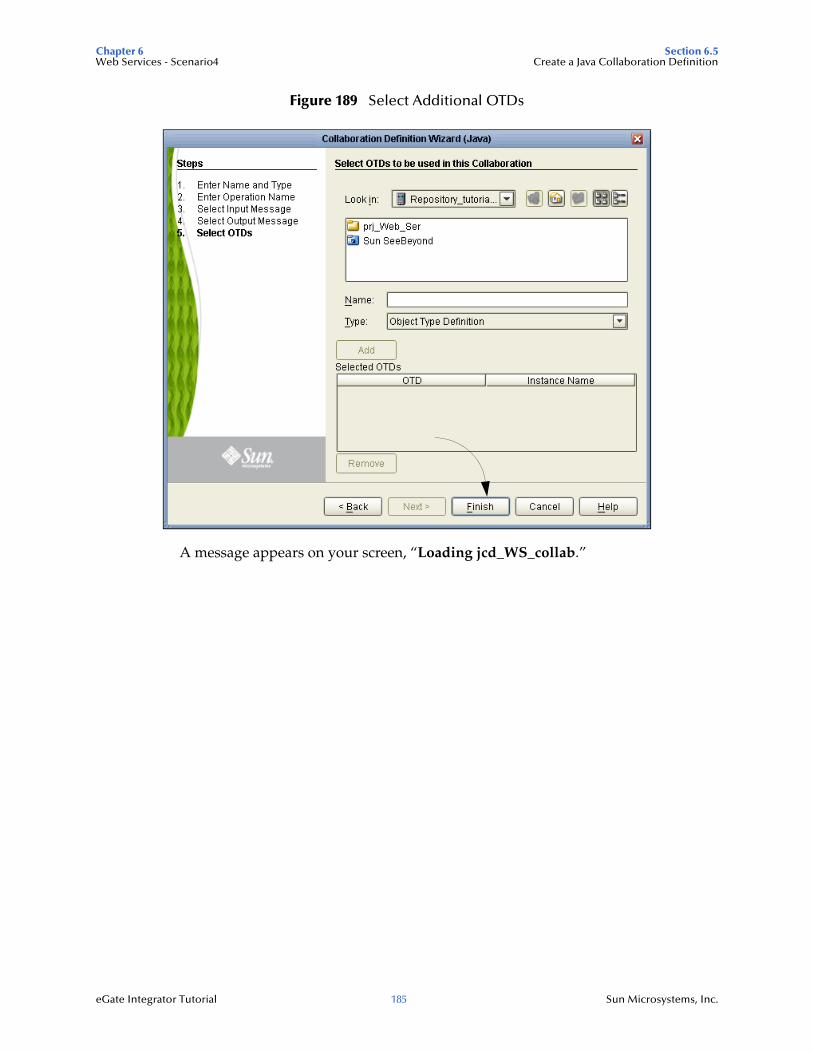
Chapter 6 Section 6.5Web Services - Scenario4 Create a Java Collaboration Definition
eGate Integrator Tutorial 185 Sun Microsystems, Inc.
Figure 189 Select Additional OTDs
A message appears on your screen, “Loading jcd_WS_collab.”
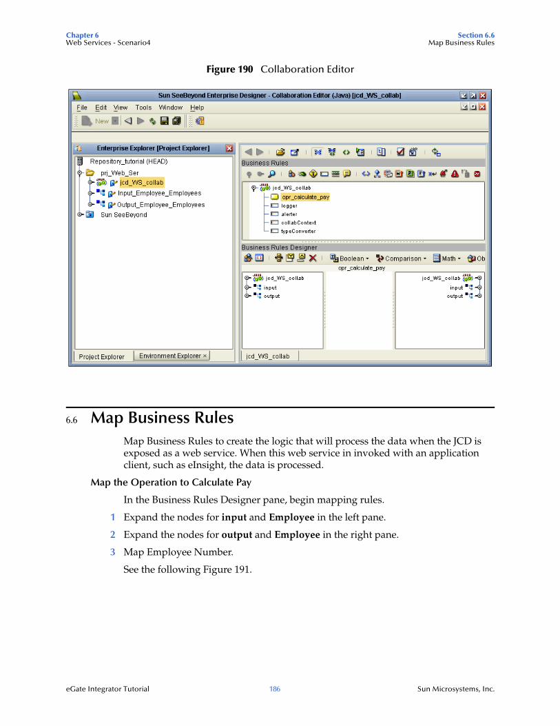
Chapter 6 Section 6.6Web Services - Scenario4 Map Business Rules
eGate Integrator Tutorial 186 Sun Microsystems, Inc.
Figure 190 Collaboration Editor
6.6 Map Business RulesMap Business Rules to create the logic that will process the data when the JCD is exposed as a web service. When this web service in invoked with an application client, such as eInsight, the data is processed.
Map the Operation to Calculate Pay
In the Business Rules Designer pane, begin mapping rules.
1 Expand the nodes for input and Employee in the left pane.
2 Expand the nodes for output and Employee in the right pane.
3 Map Employee Number.
See the following Figure 191.
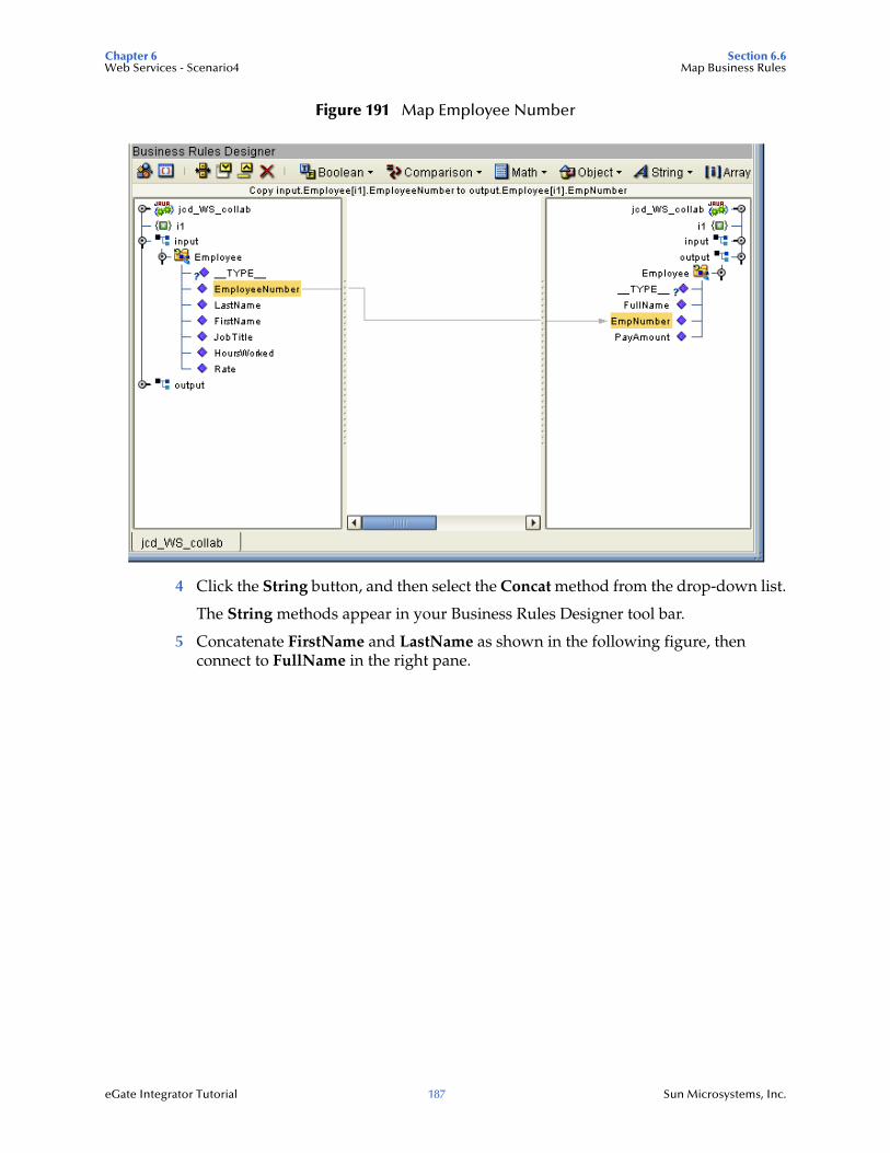
Chapter 6 Section 6.6Web Services - Scenario4 Map Business Rules
eGate Integrator Tutorial 187 Sun Microsystems, Inc.
Figure 191 Map Employee Number
4 Click the String button, and then select the Concat method from the drop-down list.
The String methods appear in your Business Rules Designer tool bar.
5 Concatenate FirstName and LastName as shown in the following figure, then connect to FullName in the right pane.
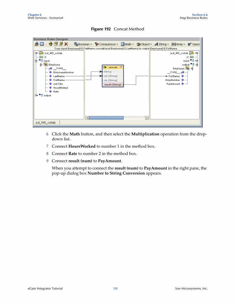
Chapter 6 Section 6.6Web Services - Scenario4 Map Business Rules
eGate Integrator Tutorial 188 Sun Microsystems, Inc.
Figure 192 Concat Method
6 Click the Math button, and then select the Multiplication operation from the drop-down list.
7 Connect HoursWorked to number 1 in the method box.
8 Connect Rate to number 2 in the method box.
9 Connect result (num) to PayAmount.
When you attempt to connect the result (num) to PayAmount in the right pane, the pop-up dialog box Number to String Conversion appears.
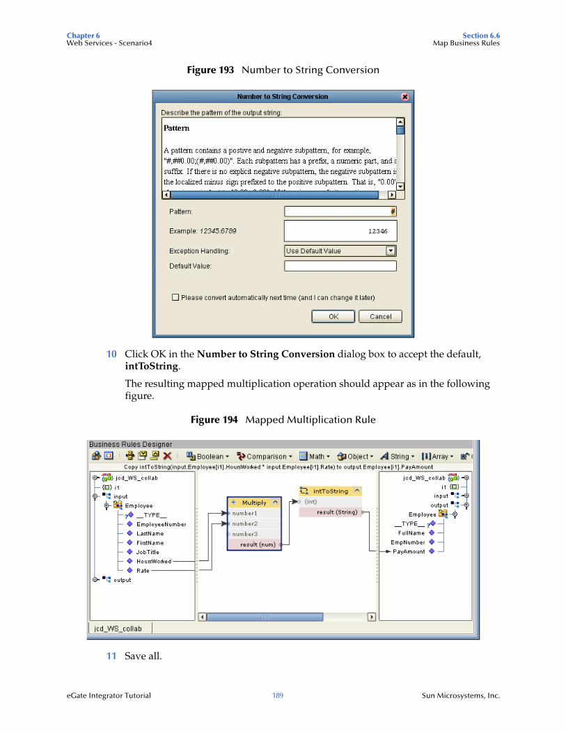
Chapter 6 Section 6.6Web Services - Scenario4 Map Business Rules
eGate Integrator Tutorial 189 Sun Microsystems, Inc.
Figure 193 Number to String Conversion
10 Click OK in the Number to String Conversion dialog box to accept the default, intToString.
The resulting mapped multiplication operation should appear as in the following figure.
Figure 194 Mapped Multiplication Rule
11 Save all.
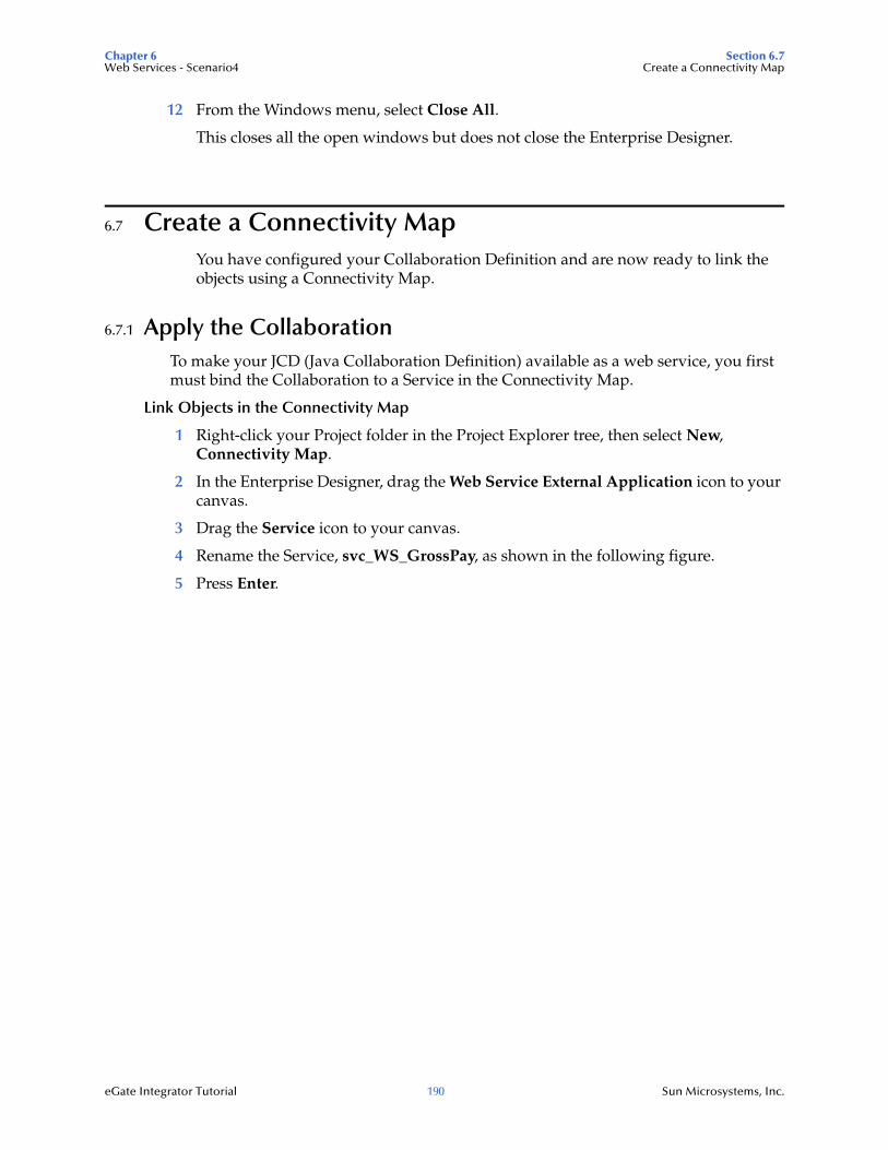
Chapter 6 Section 6.7Web Services - Scenario4 Create a Connectivity Map
eGate Integrator Tutorial 190 Sun Microsystems, Inc.
12 From the Windows menu, select Close All.
This closes all the open windows but does not close the Enterprise Designer.
6.7 Create a Connectivity MapYou have configured your Collaboration Definition and are now ready to link the objects using a Connectivity Map.
6.7.1 Apply the CollaborationTo make your JCD (Java Collaboration Definition) available as a web service, you first must bind the Collaboration to a Service in the Connectivity Map.
Link Objects in the Connectivity Map
1 Right-click your Project folder in the Project Explorer tree, then select New, Connectivity Map.
2 In the Enterprise Designer, drag the Web Service External Application icon to your canvas.
3 Drag the Service icon to your canvas.
4 Rename the Service, svc_WS_GrossPay, as shown in the following figure.
5 Press Enter.
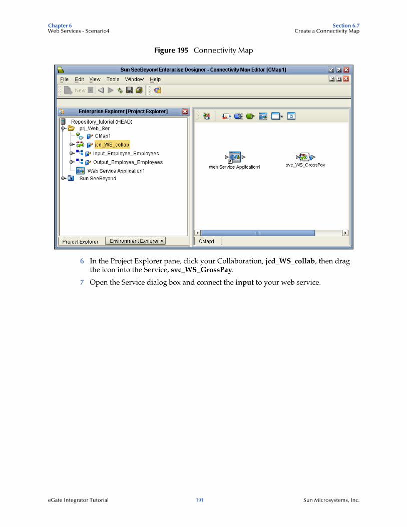
Chapter 6 Section 6.7Web Services - Scenario4 Create a Connectivity Map
eGate Integrator Tutorial 191 Sun Microsystems, Inc.
Figure 195 Connectivity Map
6 In the Project Explorer pane, click your Collaboration, jcd_WS_collab, then drag the icon into the Service, svc_WS_GrossPay.
7 Open the Service dialog box and connect the input to your web service.
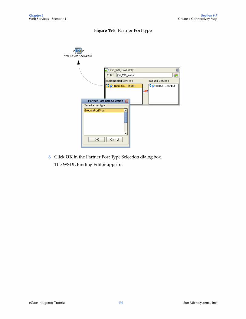
Chapter 6 Section 6.7Web Services - Scenario4 Create a Connectivity Map
eGate Integrator Tutorial 192 Sun Microsystems, Inc.
Figure 196 Partner Port type
8 Click OK in the Partner Port Type Selection dialog box.
The WSDL Binding Editor appears.
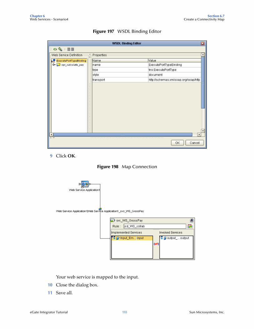
Chapter 6 Section 6.7Web Services - Scenario4 Create a Connectivity Map
eGate Integrator Tutorial 193 Sun Microsystems, Inc.
Figure 197 WSDL Binding Editor
9 Click OK.
Figure 198 Map Connection
Your web service is mapped to the input.
10 Close the dialog box.
11 Save all.
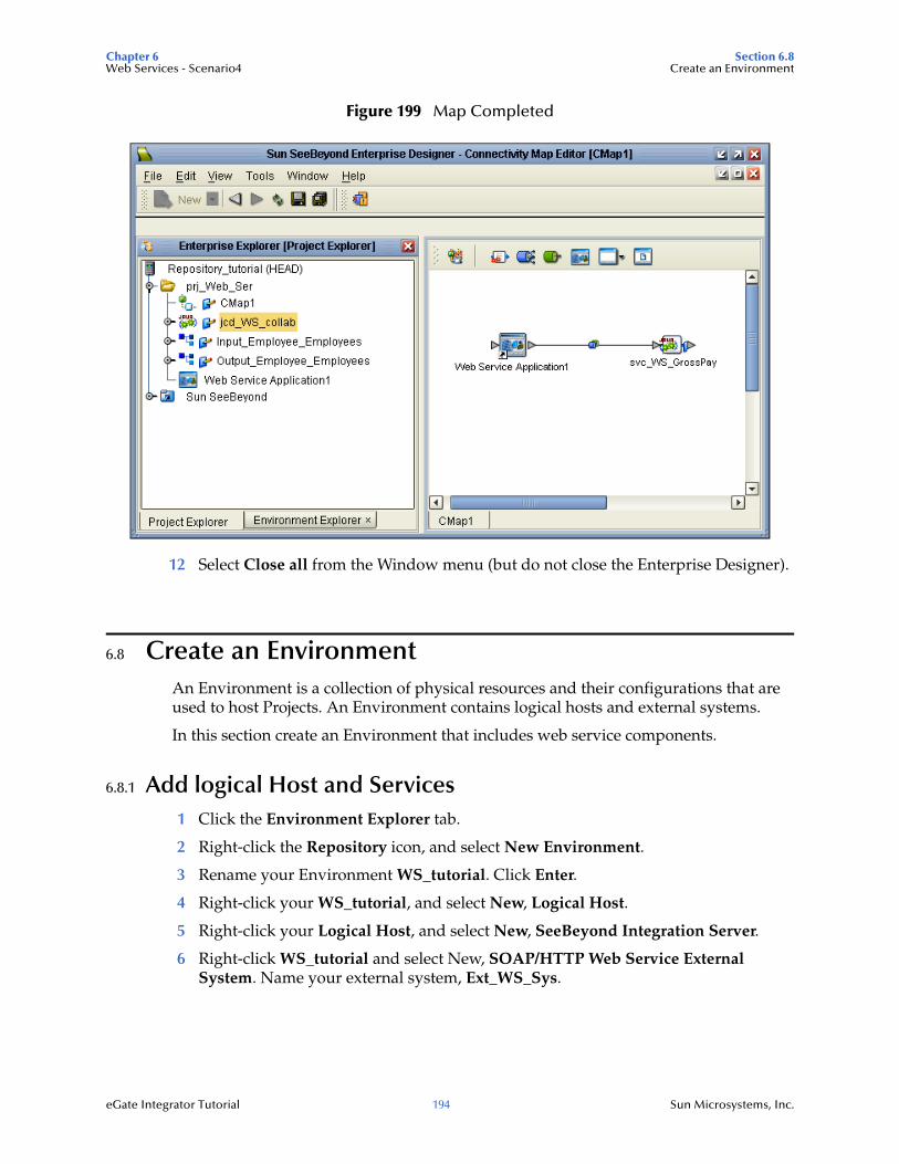
Chapter 6 Section 6.8Web Services - Scenario4 Create an Environment
eGate Integrator Tutorial 194 Sun Microsystems, Inc.
Figure 199 Map Completed
12 Select Close all from the Window menu (but do not close the Enterprise Designer).
6.8 Create an EnvironmentAn Environment is a collection of physical resources and their configurations that are used to host Projects. An Environment contains logical hosts and external systems.
In this section create an Environment that includes web service components.
6.8.1 Add logical Host and Services1 Click the Environment Explorer tab.
2 Right-click the Repository icon, and select New Environment.
3 Rename your Environment WS_tutorial. Click Enter.
4 Right-click your WS_tutorial, and select New, Logical Host.
5 Right-click your Logical Host, and select New, SeeBeyond Integration Server.
6 Right-click WS_tutorial and select New, SOAP/HTTP Web Service External System. Name your external system, Ext_WS_Sys.
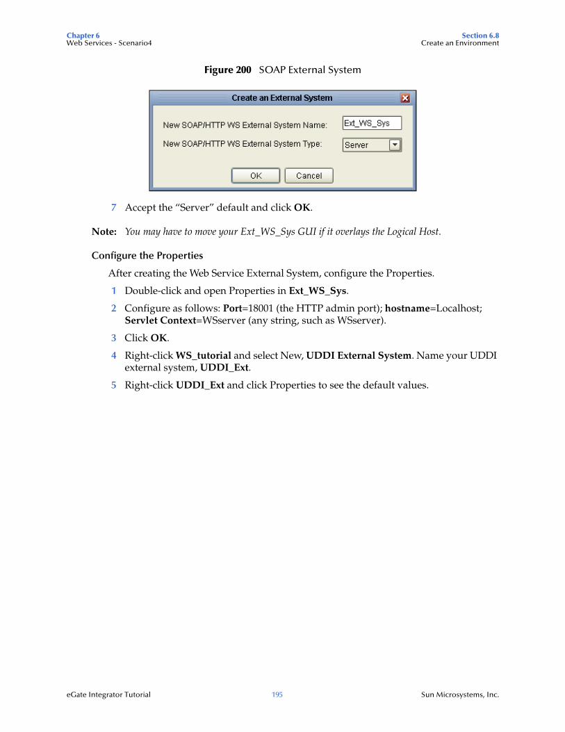
Chapter 6 Section 6.8Web Services - Scenario4 Create an Environment
eGate Integrator Tutorial 195 Sun Microsystems, Inc.
Figure 200 SOAP External System
7 Accept the “Server” default and click OK.
Note: You may have to move your Ext_WS_Sys GUI if it overlays the Logical Host.
Configure the Properties
After creating the Web Service External System, configure the Properties.
1 Double-click and open Properties in Ext_WS_Sys.
2 Configure as follows: Port=18001 (the HTTP admin port); hostname=Localhost; Servlet Context=WSserver (any string, such as WSserver).
3 Click OK.
4 Right-click WS_tutorial and select New, UDDI External System. Name your UDDI external system, UDDI_Ext.
5 Right-click UDDI_Ext and click Properties to see the default values.
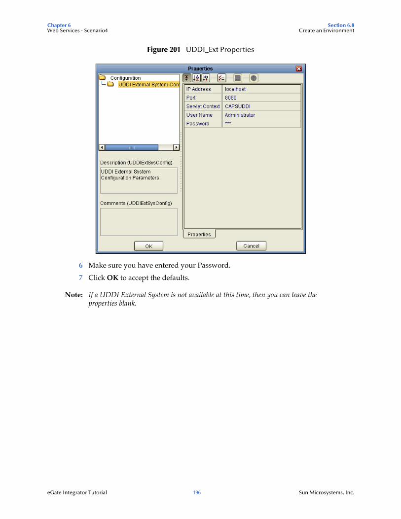
Chapter 6 Section 6.8Web Services - Scenario4 Create an Environment
eGate Integrator Tutorial 196 Sun Microsystems, Inc.
Figure 201 UDDI_Ext Properties
6 Make sure you have entered your Password.
7 Click OK to accept the defaults.
Note: If a UDDI External System is not available at this time, then you can leave the properties blank.
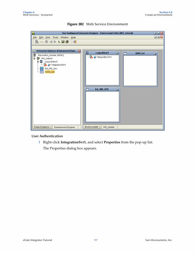
Chapter 6 Section 6.8Web Services - Scenario4 Create an Environment
eGate Integrator Tutorial 197 Sun Microsystems, Inc.
Figure 202 Web Service Environment
User Authentication
1 Right-click IntegrationSvr1, and select Properties from the pop-up list.
The Properties dialog box appears.
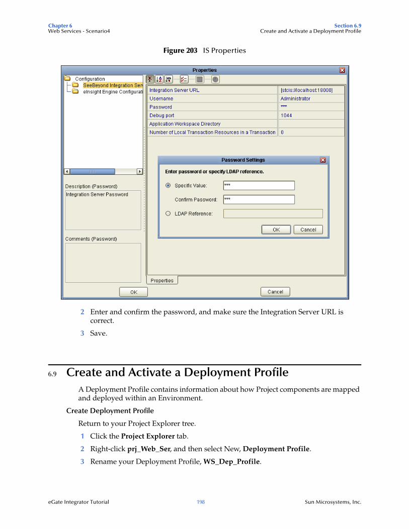
Chapter 6 Section 6.9Web Services - Scenario4 Create and Activate a Deployment Profile
eGate Integrator Tutorial 198 Sun Microsystems, Inc.
Figure 203 IS Properties
2 Enter and confirm the password, and make sure the Integration Server URL is correct.
3 Save.
6.9 Create and Activate a Deployment ProfileA Deployment Profile contains information about how Project components are mapped and deployed within an Environment.
Create Deployment Profile
Return to your Project Explorer tree.
1 Click the Project Explorer tab.
2 Right-click prj_Web_Ser, and then select New, Deployment Profile.
3 Rename your Deployment Profile, WS_Dep_Profile.
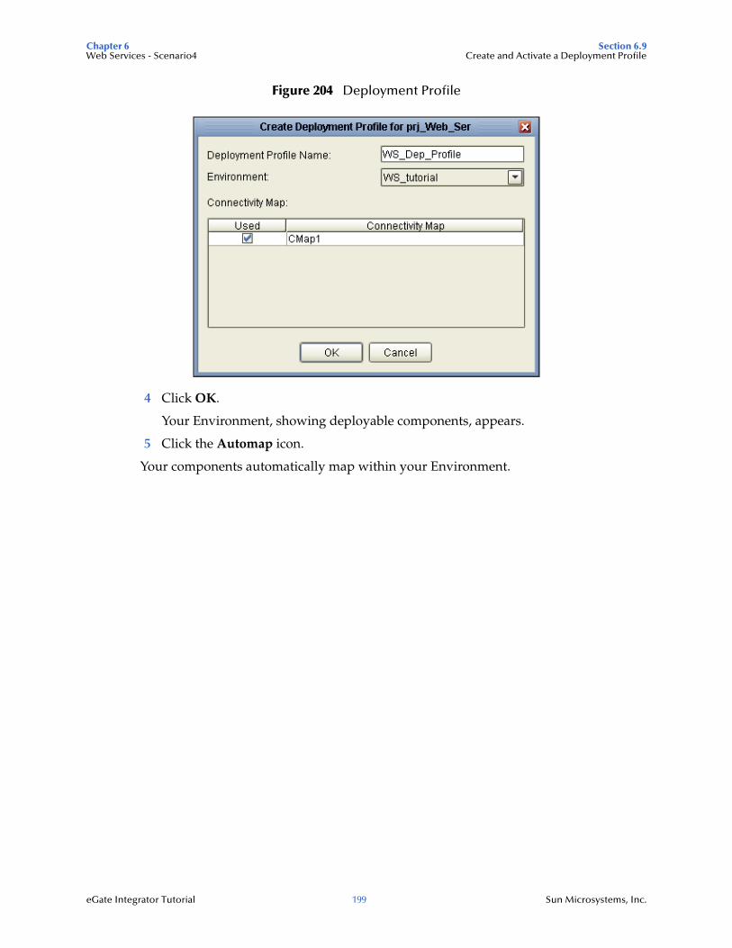
Chapter 6 Section 6.9Web Services - Scenario4 Create and Activate a Deployment Profile
eGate Integrator Tutorial 199 Sun Microsystems, Inc.
Figure 204 Deployment Profile
4 Click OK.
Your Environment, showing deployable components, appears.
5 Click the Automap icon.
Your components automatically map within your Environment.
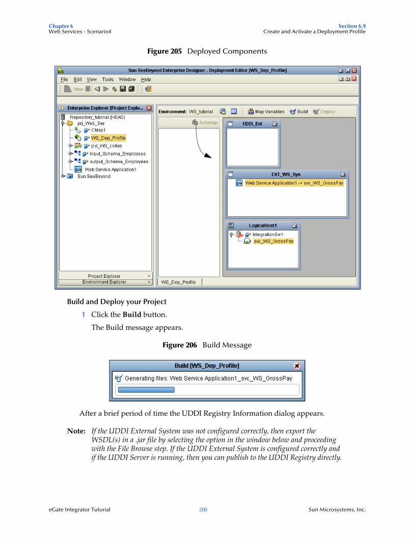
Chapter 6 Section 6.9Web Services - Scenario4 Create and Activate a Deployment Profile
eGate Integrator Tutorial 200 Sun Microsystems, Inc.
Figure 205 Deployed Components
Build and Deploy your Project
1 Click the Build button.
The Build message appears.
Figure 206 Build Message
After a brief period of time the UDDI Registry Information dialog appears.
Note: If the UDDI External System was not configured correctly, then export the WSDL(s) in a .jar file by selecting the option in the window below and proceeding with the File Browse step. If the UDDI External System is configured correctly and if the UDDI Server is running, then you can publish to the UDDI Registry directly.
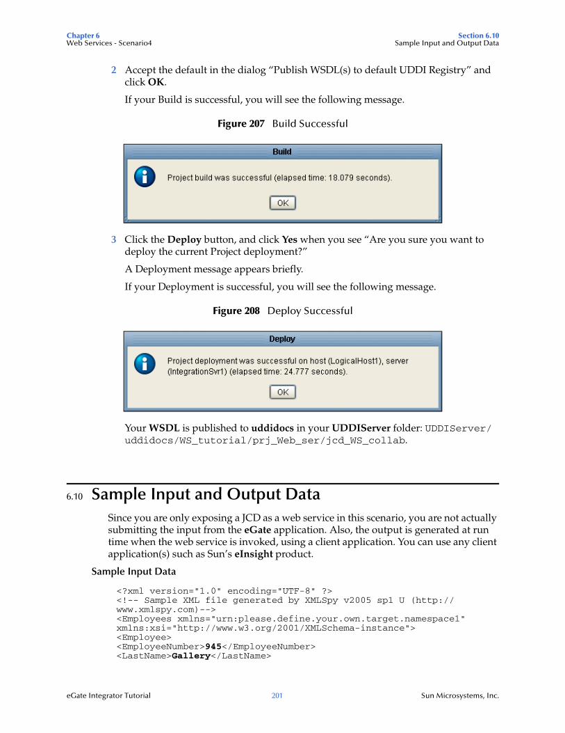
Chapter 6 Section 6.10Web Services - Scenario4 Sample Input and Output Data
eGate Integrator Tutorial 201 Sun Microsystems, Inc.
2 Accept the default in the dialog “Publish WSDL(s) to default UDDI Registry” and click OK.
If your Build is successful, you will see the following message.
Figure 207 Build Successful
3 Click the Deploy button, and click Yes when you see “Are you sure you want to deploy the current Project deployment?”
A Deployment message appears briefly.
If your Deployment is successful, you will see the following message.
Figure 208 Deploy Successful
Your WSDL is published to uddidocs in your UDDIServer folder: UDDIServer/uddidocs/WS_tutorial/prj_Web_ser/jcd_WS_collab.
6.10 Sample Input and Output DataSince you are only exposing a JCD as a web service in this scenario, you are not actually submitting the input from the eGate application. Also, the output is generated at run time when the web service is invoked, using a client application. You can use any client application(s) such as Sun’s eInsight product.
Sample Input Data
<?xml version="1.0" encoding="UTF-8" ?> <!-- Sample XML file generated by XMLSpy v2005 sp1 U (http://www.xmlspy.com)--> <Employees xmlns="urn:please.define.your.own.target.namespace1" xmlns:xsi="http://www.w3.org/2001/XMLSchema-instance"> <Employee> <EmployeeNumber>945</EmployeeNumber> <LastName>Gallery</LastName>
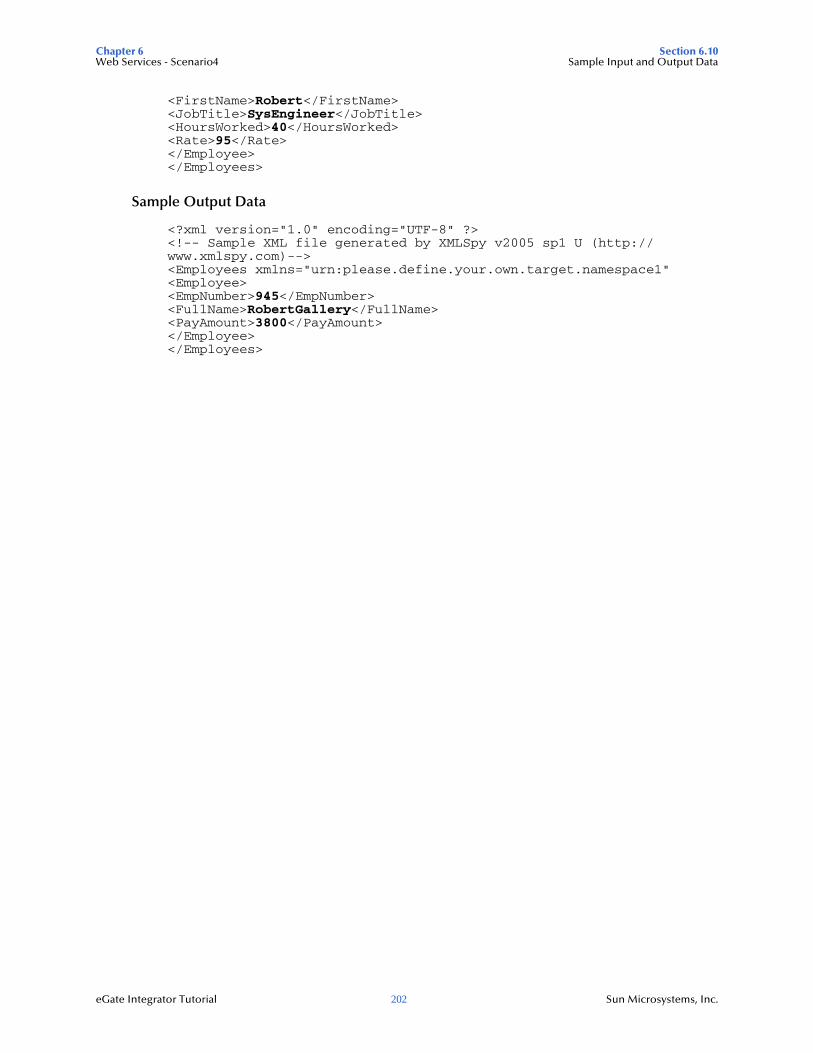
Chapter 6 Section 6.10Web Services - Scenario4 Sample Input and Output Data
eGate Integrator Tutorial 202 Sun Microsystems, Inc.
<FirstName>Robert</FirstName> <JobTitle>SysEngineer</JobTitle> <HoursWorked>40</HoursWorked> <Rate>95</Rate> </Employee></Employees>
Sample Output Data
<?xml version="1.0" encoding="UTF-8" ?> <!-- Sample XML file generated by XMLSpy v2005 sp1 U (http://www.xmlspy.com)--> <Employees xmlns="urn:please.define.your.own.target.namespace1" <Employee><EmpNumber>945</EmpNumber><FullName>RobertGallery</FullName><PayAmount>3800</PayAmount></Employee></Employees>
eGate Integrator Tutorial 203 Sun Microsystems, Inc.
Chapter 7
Enterprise Manager Overview
For more detailed information about the Enterprise Manager see the eGate Integrator System Administration Guide and Java Composite Application Platform Suite Installation Guide. This chapter provides a quick overview only.
The Enterprise Manager is a powerful monitoring tool that is useful for troubleshooting and monitoring system activity.
Although the Enterprise Manager Monitor is not required for the tutorials, you may want to have it open so that you can become familiar with its functionality.
What’s in This Chapter
Install and Run the Enterprise Manager on page 203
Install the eWay Monitor and File eWay Monitor on page 205
Monitor your Project on page 208
7.1 Install and Run the Enterprise ManagerAfter you have downloaded the Enterprise Manager-Monitoring and Administration component, you can proceed to install and run the Enterprise Manager to monitor your Project in real time.
Install the Enterprise Manager
Execute install.bat from your emanager subdirectory of your CAPS directory.
Start the Enterprise Manager
Execute startserver.bat from your CAPS emanager folder.
Access the Enterprise Manager as a Web Service
Use the URL http://<hostname>:<port_number>
where <hostname> is the fully qualified (although “localhost” is used in some of the examples), network addressable host name
and <port_number> is the Enterprise Manager port number
For example: http://johndoe.stc.com:15000 or http://localhost:15000.
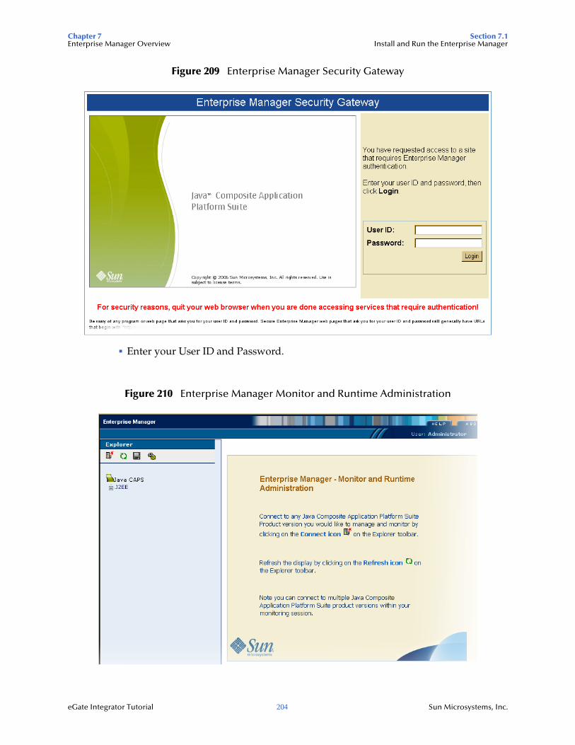
Chapter 7 Section 7.1Enterprise Manager Overview Install and Run the Enterprise Manager
eGate Integrator Tutorial 204 Sun Microsystems, Inc.
Figure 209 Enterprise Manager Security Gateway
Enter your User ID and Password.
Figure 210 Enterprise Manager Monitor and Runtime Administration

Chapter 7 Section 7.2Enterprise Manager Overview Install the eWay Monitor and File eWay Monitor
eGate Integrator Tutorial 205 Sun Microsystems, Inc.
Add a Runtime Server
Add a Runtime Server. For the example shown below, make sure your domain\integration server is runnig.
1 Expand the nodes under J2EE and select Deployer in the Explorer Tree in the left pane.
2 Click the Manage Servers tab.
3 Click Add New Server and enter the required information. See the following figure.
Figure 211 Add Runtime Server
7.2 Install the eWay Monitor and File eWay MonitorEnsure that both the File eWay Monitor and the eWay Monitor are installed on the Enterprise Manager server.
Use the Enterprise Manager to install these applications.
1 Click the Configuration Icon on the Explorer tool bar in the Enterprise Manager.
2 Click the Web Application Manager tab, then select the Auto-Install From Repository tab.
See the following figure.
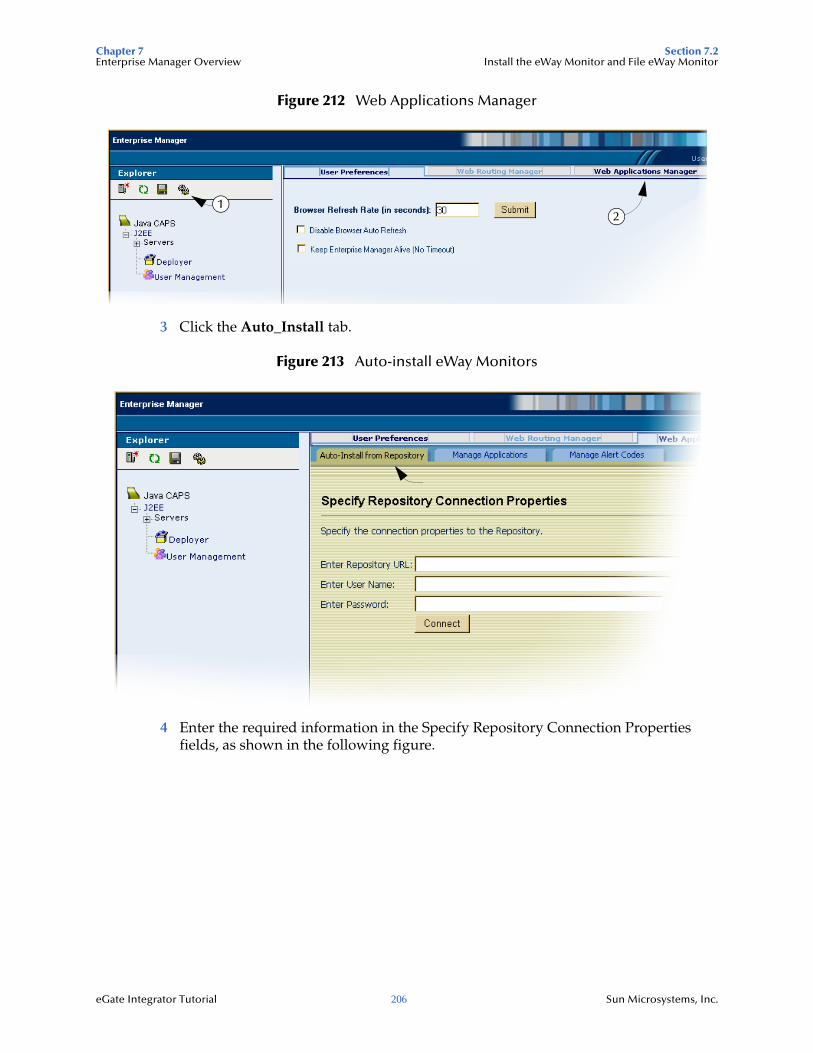
Chapter 7 Section 7.2Enterprise Manager Overview Install the eWay Monitor and File eWay Monitor
eGate Integrator Tutorial 206 Sun Microsystems, Inc.
Figure 212 Web Applications Manager
3 Click the Auto_Install tab.
Figure 213 Auto-install eWay Monitors
4 Enter the required information in the Specify Repository Connection Properties fields, as shown in the following figure.
12
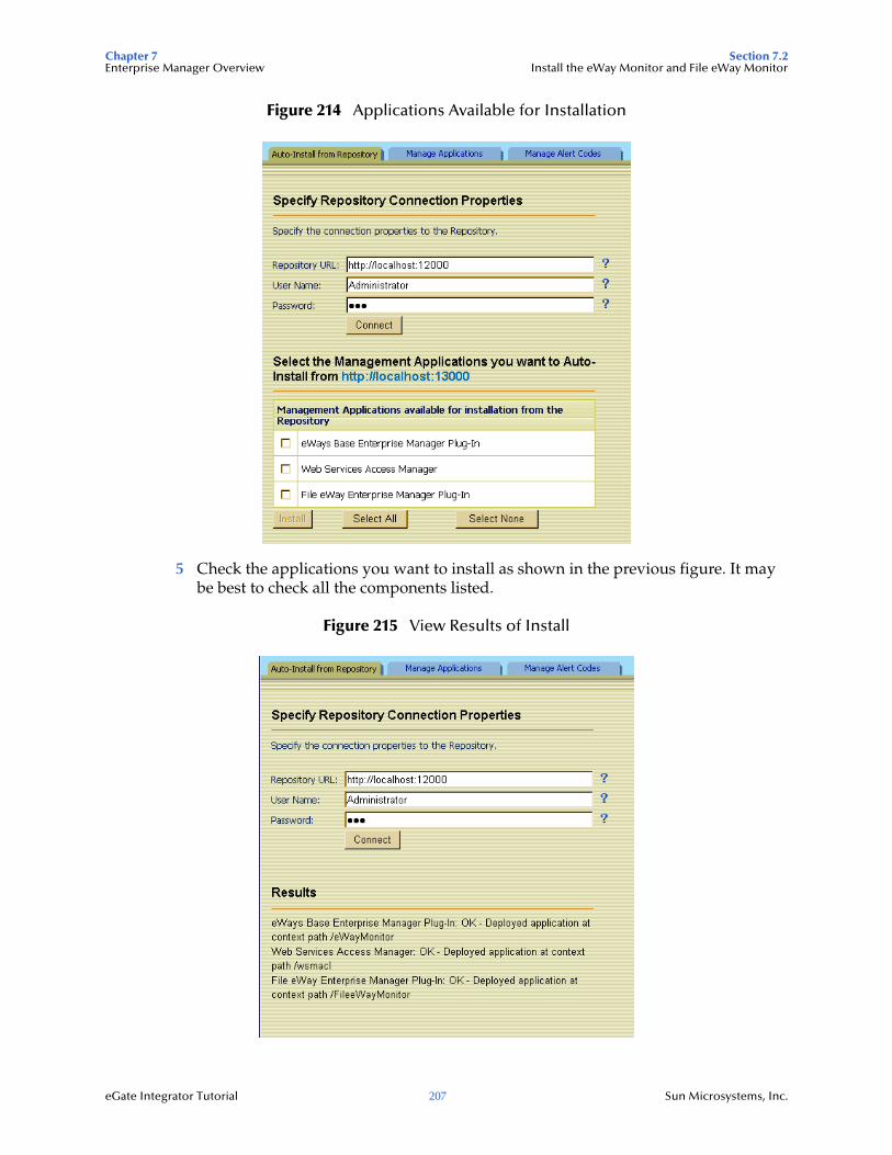
Chapter 7 Section 7.2Enterprise Manager Overview Install the eWay Monitor and File eWay Monitor
eGate Integrator Tutorial 207 Sun Microsystems, Inc.
Figure 214 Applications Available for Installation
5 Check the applications you want to install as shown in the previous figure. It may be best to check all the components listed.
Figure 215 View Results of Install
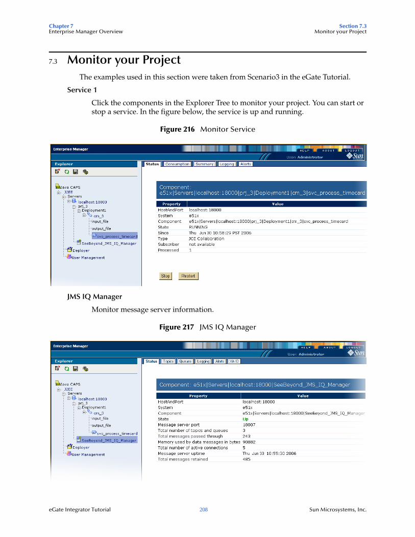
Chapter 7 Section 7.3Enterprise Manager Overview Monitor your Project
eGate Integrator Tutorial 208 Sun Microsystems, Inc.
7.3 Monitor your ProjectThe examples used in this section were taken from Scenario3 in the eGate Tutorial.
Service 1
Click the components in the Explorer Tree to monitor your project. You can start or stop a service. In the figure below, the service is up and running.
Figure 216 Monitor Service
JMS IQ Manager
Monitor message server information.
Figure 217 JMS IQ Manager
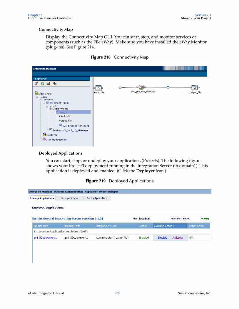
Chapter 7 Section 7.3Enterprise Manager Overview Monitor your Project
eGate Integrator Tutorial 209 Sun Microsystems, Inc.
Connectivity Map
Display the Connectivity Map GUI. You can start, stop, and monitor services or components (such as the File eWay). Make sure you have installed the eWay Monitor (plug-ins). See Figure 214.
Figure 218 Connectivity Map
Deployed Applications
You can start, stop, or undeploy your applications (Projects). The following figure shows your Project3 deployment running in the Integration Server (in domain1). This application is deployed and enabled. (Click the Deployer icon.)
Figure 219 Deployed Applications
eGate Integrator Tutorial 210 Sun Microsystems, Inc.
Glossary
CAPSComposite Application Platform Suite.
CollaborationA logical operation performed between some combination of message destinations and external applications. The operation is defined by a Collaboration Definition, which can be encoded in either Java or XSLT.
Also see “Service” and “Collaboration Definition”.
Collaboration DefinitionThe encoding of business rules, in Java or XSLT format. Typically, the encoding consists of operations on OTDs (see “OTD”). Several Collaborations can have the same Collaboration Definition.
ConnectionConsists of the configuration information that enables an eWay to connect to an external system.
Connectivity MapContains business logic and routing information about the data transmission. A Connectivity Map usually includes one or more Collaborations, topics, queues, and eWays. A Connectivity Map is created under a Project. A Project may have multiple Connectivity Maps.
Deployment ProfileContains the information about how the Project components will be deployed in an Environment. A Project can have multiple Deployment Profiles, but only one Deployment Profile can be activated for a Project in any one Environment.
EnvironmentA collection of physical resources and their configurations that are used to host Project components. An Environment contains logical hosts and external systems.
eWayA link between a Collaboration and an external connection including the message server connection (topic or queue) or external application.
External ApplicationA logical representation in an eGate Project of an external application.
External SystemA representation in an eGate Project of an external application system.
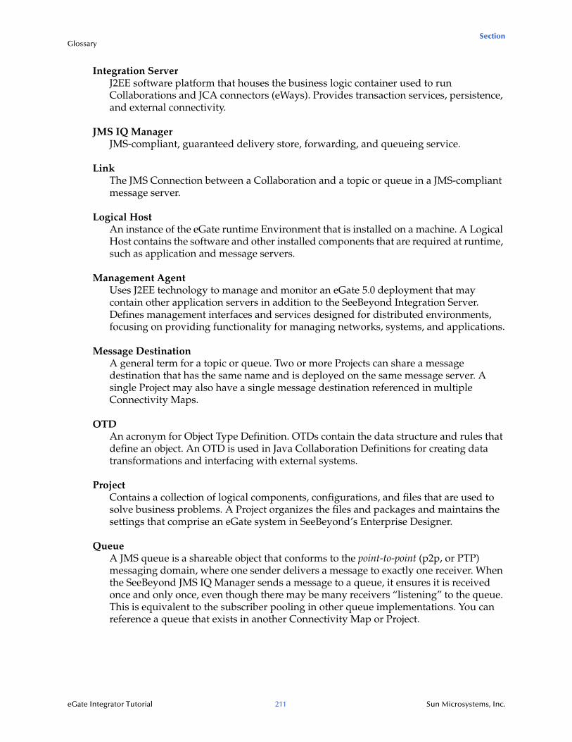
Section Glossary
eGate Integrator Tutorial 211 Sun Microsystems, Inc.
Integration ServerJ2EE software platform that houses the business logic container used to run Collaborations and JCA connectors (eWays). Provides transaction services, persistence, and external connectivity.
JMS IQ ManagerJMS-compliant, guaranteed delivery store, forwarding, and queueing service.
LinkThe JMS Connection between a Collaboration and a topic or queue in a JMS-compliant message server.
Logical HostAn instance of the eGate runtime Environment that is installed on a machine. A Logical Host contains the software and other installed components that are required at runtime, such as application and message servers.
Management AgentUses J2EE technology to manage and monitor an eGate 5.0 deployment that may contain other application servers in addition to the SeeBeyond Integration Server. Defines management interfaces and services designed for distributed environments, focusing on providing functionality for managing networks, systems, and applications.
Message DestinationA general term for a topic or queue. Two or more Projects can share a message destination that has the same name and is deployed on the same message server. A single Project may also have a single message destination referenced in multiple Connectivity Maps.
OTDAn acronym for Object Type Definition. OTDs contain the data structure and rules that define an object. An OTD is used in Java Collaboration Definitions for creating data transformations and interfacing with external systems.
ProjectContains a collection of logical components, configurations, and files that are used to solve business problems. A Project organizes the files and packages and maintains the settings that comprise an eGate system in SeeBeyond’s Enterprise Designer.
QueueA JMS queue is a shareable object that conforms to the point-to-point (p2p, or PTP) messaging domain, where one sender delivers a message to exactly one receiver. When the SeeBeyond JMS IQ Manager sends a message to a queue, it ensures it is received once and only once, even though there may be many receivers “listening” to the queue. This is equivalent to the subscriber pooling in other queue implementations. You can reference a queue that exists in another Connectivity Map or Project.
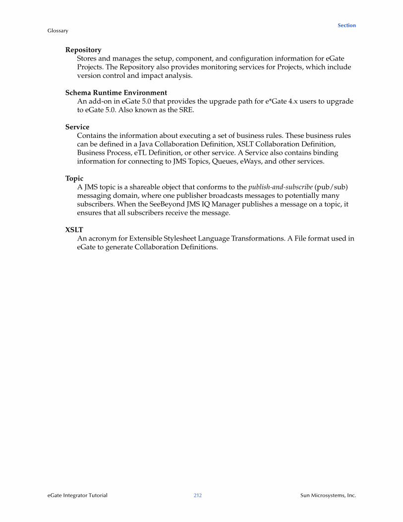
Section Glossary
eGate Integrator Tutorial 212 Sun Microsystems, Inc.
RepositoryStores and manages the setup, component, and configuration information for eGate Projects. The Repository also provides monitoring services for Projects, which include version control and impact analysis.
Schema Runtime EnvironmentAn add-on in eGate 5.0 that provides the upgrade path for e*Gate 4.x users to upgrade to eGate 5.0. Also known as the SRE.
ServiceContains the information about executing a set of business rules. These business rules can be defined in a Java Collaboration Definition, XSLT Collaboration Definition, Business Process, eTL Definition, or other service. A Service also contains binding information for connecting to JMS Topics, Queues, eWays, and other services.
TopicA JMS topic is a shareable object that conforms to the publish-and-subscribe (pub/sub) messaging domain, where one publisher broadcasts messages to potentially many subscribers. When the SeeBeyond JMS IQ Manager publishes a message on a topic, it ensures that all subscribers receive the message.
XSLTAn acronym for Extensible Stylesheet Language Transformations. A File format used in eGate to generate Collaboration Definitions.
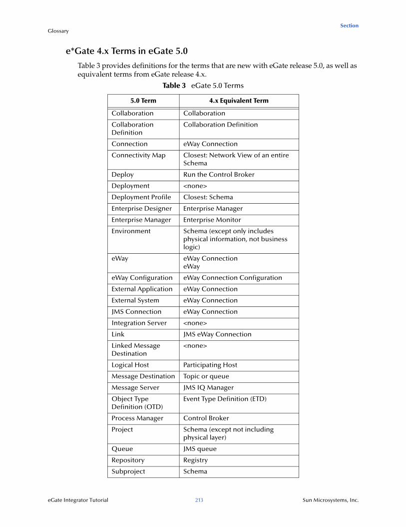
Section Glossary
eGate Integrator Tutorial 213 Sun Microsystems, Inc.
e*Gate 4.x Terms in eGate 5.0
Table 3 provides definitions for the terms that are new with eGate release 5.0, as well as equivalent terms from eGate release 4.x.
Table 3 eGate 5.0 Terms
5.0 Term 4.x Equivalent Term
Collaboration Collaboration
Collaboration Definition
Collaboration Definition
Connection eWay Connection
Connectivity Map Closest: Network View of an entire Schema
Deploy Run the Control Broker
Deployment <none>
Deployment Profile Closest: Schema
Enterprise Designer Enterprise Manager
Enterprise Manager Enterprise Monitor
Environment Schema (except only includes physical information, not business logic)
eWay eWay ConnectioneWay
eWay Configuration eWay Connection Configuration
External Application eWay Connection
External System eWay Connection
JMS Connection eWay Connection
Integration Server <none>
Link JMS eWay Connection
Linked Message Destination
<none>
Logical Host Participating Host
Message Destination Topic or queue
Message Server JMS IQ Manager
Object Type Definition (OTD)
Event Type Definition (ETD)
Process Manager Control Broker
Project Schema (except not including physical layer)
Queue JMS queue
Repository Registry
Subproject Schema
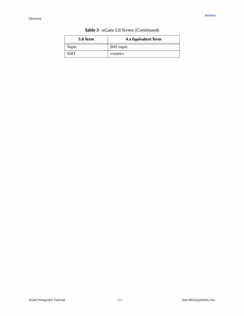
Section Glossary
eGate Integrator Tutorial 214 Sun Microsystems, Inc.
Topic JMS topic
XSLT <none>
Table 3 eGate 5.0 Terms (Continued)
5.0 Term 4.x Equivalent Term
Index
eGate Integrator Tutorial 215 Sun Microsystems, Inc.
Index
BBuild and Deploy Project 64, 122, 165Business Designer - Unmarshal Text 44, 148Business Rules
Business Rules Designer window 91for Scenario1 43for Scenario2 91for Scenario3 146Multiplication logic 99Objects - in the Business Rules Designer window
(see note) 91
CCAPS 210Collaboration 210, 213Collaboration definition 210, 213Collaboration Editor (Java)
Defined in a project 20Collaboration Editor (XSLT)
Defined in a project 20Component
an object that is runable such as a Java Collaboration 16
Connection 210, 213Connectivity Map 210, 213
Add components 52, 106, 154Create 50, 104, 153Default name, CMap1 51Defined in a project 20Graphic 27, 73, 126Graphic, unlinked 54, 109Link components 54, 108
Control Broker 213conventions, text 15
DDeployment 213Deployment Profile 210, 213
definition 62Deployment Profile Editor
Defined in a project 20Domain
an instance of the Logical Host 64
EeGate Integrator 14Enterprise Designer 213
Create a new project 29, 75Create a new project using XSD OTDs 129Create and configure components 18Editor 20Features 18GUI 19Project 20Start the Enterprise Designer 29, 76, 130
Enterprise ExplorerCreate a connectivity map 50Create and name a project 130Organize components, in the left pane 20The left pane of the Enterprise Designer 19
Enterprise Manager 213Add a runtime server 205Install and Run 203Overview 203
Enterprise Monitor 213Environment 210, 213
Create environment 58Defined in a project 20LogicalHost1 59, 115New File External System 59, 116
Environment ExplorerAccessed from View menu 19Collection of logical hosts 20Create environment 58
ETD 213Event Type Definition 213eWay 210, 213
Configure 111Graphic 56, 112, 158Input eWay 111Link between External Application and a
Service 54, 108, 156Output eWay 111
eWay Configuration 213eWay Connection 213eWay Connection Configuration 213External
application 210system 210
External Applications 52, 107, 154
FFileClient
Web service (in the Tutorial used to receive or write data) 38, 142
Index
eGate Integrator Tutorial 216 Sun Microsystems, Inc.
IImport 131Input
Inbound eWay 27, 73, 126Input file 69, 124, 170Input.dtd, create input file 25InputFS 73
Integration Server 211, 213Introduction 14, 18
JJMS
connection 213e*Way Connection 213IQ Manager 213JMS Client Configuration 114queue 213topic 214
JMS IQ Manager 211
Llink 211, 213linked message destination 213Logical Host 211, 213
an install directory of one or more domains (instances). 58
LoginLogin menu 29, 76, 130, 176
MManagement Agent 211Menu Bar 19message
destination 211, 213server 213
Multiple records 113
NNaming conventions
Prefix 73network view 213
OObject
Generic term for component - includes eWays (see component) 16
Object Type Definition 211, 213using a DTD 31
OTD 211, 213Create OTD 31
OTD EditorDefined in a project 20
OutputOutbound eWay 27, 73, 126Output file 69, 123, 170Output XML, create output file 26OutputFS 27, 73, 126
PParticipating Host 213Passwords
Integration server and JMS IQ Manager 165Polling interval 57, 159Process Manager 213Project 211, 213
Configure input 36, 86Configure output 93Create and name 76, 130Create OTD 31Default name, Project1 50Deployment 58Drop down arrow 98Expose a JCD as a web service 172Graphic, showing components 54, 156Overview 72Verify output 68, 123, 169
Project Diagram 28, 74, 127Project Editor
Part of Enterprise Designer 20Project Explorer
definition 20Properties configuration 57, 112, 159
Qqueue 211, 213
RRegistry 213Repository 212, 213Rules 91
SSample files
download for scenario 1 23Save
Save 34Save All 34
Index
eGate Integrator Tutorial 217 Sun Microsystems, Inc.
Scenario1 (Building a Project) 21Scenario2 (Building a Project) 71Scenario3
(Building a Project) 125Schema 213Schema Runtime Environment 212Security Server 212Service 36
file-read service 38, 88, 142Web service 39, 89, 142wizards 36, 86
SRE 212subproject 213supporting documents 16
Ttext conventions 15Time Card system 25Timecard_to_topic 27, 73, 126Topic
Create a Topic 108Topic1 73
topic 212, 213, 214Topic_to_Payroll_out 73
WWeb Services 172
expose a JCD as a web service 172Windows
The Tutorials run on a Windows system 14
XXML
file 56XSLT 212, 214