seismic design methodology for friction damped braced frames
TRANSCRIPT
EARTHQUAKE ENGINEERING AND STRUCTURAL DYNAMICSEarthquake Engng Struct. Dyn. 2000; 29: 1569}1585
Seismic design methodology for friction damped braced frames
Robert Levy1,*, Eduard Marianchik1, Avigdor Rutenberg1 and Fred Segal2
1 Faculty of Civil Engineering, Technion } Israel Institute of Technology, Technion City, Haifa 32000, Israel2 Israel Electric Company Ltd, Haifa, Israel
SUMMARY
This paper is concerned with the design of steel frames using friction damped slotted bolted connections(SBCs) in the diagonal braces. A dynamic model is developed to describe the behaviour of a single-degree-of-freedom (SDOF) steel frame that uses bilinear hysteretic behaviour for the damper. This model is generalizedto MDOF systems. A novel algorithm for displacement reversal in the transition from slip to stick ispresented. It uses numerical noise for its success. A design procedure that attains the sti!ness of theindividual braces and their elongation at the threshold of activation is then applied to a 10-storey steelframe. This design process is a two-phase iterative procedure that converges quite fast. Copyright ( 2000John Wiley & Sons, Ltd.
KEY WORDS: steel structures; earthquake engineering; friction dampers braced frames; bilinear hysteresis
1. INTRODUCTION
Dissipation of energy during strong earthquakes using mechanical means independent of themain structure is coming out of its conceptual research stage into practical applications wheredevices are actually used. Friction dampers, which are designed to slip at a certain predeterminedlevel, have been successfully applied to steel structures as braces [1]. Friction causes a majorportion of the seismic energy to be dissipated, thus leaving the structure intact, i.e. without itsmembers having to yield. Basically, two parts of the brace with slotted holes are connected byhigh strength bolts that may have a lining pad in-between. SBCs are relatively easy to constructand implement, and use commercially available materials. They are, thus, attractive for use in theseismic design of new buildings and in retro"tting of existing structures.
Pall [1] developed and implemented a friction damper at the crossing of two braces wheretension in one of the braces forces the joint to slip thus activating four links which in turn force thejoint in the other brace to slip. Another friction device, proposed by Fitzgerald [2], utilizes slottedbolted connections (SBCs) in braced connections. Slotted connections are designed to dissipate
* Correspondence to: Robert Levy, Faculty of Civil Engineering, Technion } Israel Institute of Technology, TechnionCity, Haifa 32000, Israel.
Received 25 March 1999Revised 25 January 2000
Copyright ( 2000 John Wiley & Sons, Ltd. Accepted 18 February 2000

energy through friction between the steel surfaces along the brace in tension and compressionloading cycles. Grigorian et al. [3] proposed a similar slotted bolted connection which consistedof brass in contact with steel.
Grigorian et al. [3] tested and studied these two types of SBCs. Experimental results showedthat the behavior of connections with brass on steel is more uniform and simpler to modelanalytically than that with steel on steel. Popov et al. [4] applied SBCs to an experimental modelwhich they tested on a shaking table to "nd that SBCs were very e!ective in dissipating most ofthe input energy.
Colajanni and Papia [5] studied the dissipation capacity of friction-damper braced systems.They analysed the dynamic response of a one-storey frame and deduced approximate analyticalexpressions characterizing the hysteretic behaviour of the frame and utilized them to de"ne globalslip loads. They generalized their results to multi-storey braced frames.
This paper is concerned with the development of a mathematical dynamic model for thebehaviour of friction braced steel frames, and with obtaining optimal values for the structuralresponse using a design procedure for evaluating sti!ness of the individual braces and theirelongation at the threshold of slip.
2. DYNAMIC MODEL OF THE STRUCTURE WITH FRICTION DAMPERS
The basic analytical model is presented in Figure 1(a). It consists of a #exural frame, a linearspring to model the diagonal brace and the Coulomb slip element to model the friction damper.The velocities of the frame and of the friction damper (points A and B, respectively), the framesti!ness and the friction force can be described in the two following stages.
Stage 1: Stick stage. The velocity of the friction damper yR * is equal to zero, the sti!ness of theframe is equal to the initial sti!ness of the braced frame, and the friction force is equal to zero.Linear behaviour is assumed.
Stage 2: Sliding stage. The velocity of the friction damper yR * is equal to the velocity of theframe yR . The sti!ness of the frame is that of the frame without a brace and the friction force isequal to the slip force in the brace.
When the direction of the horizontal movement of the frame is reversed the system returns tothe "rst stage.
The multi-degree-of-freedom (MDOF) system shown in Figure 1(b) is a geometric stacking ofthe basic SDOF system.
The equation of motion of the single-degree-of-freedom bilinear hysteretic system that is usedto describe a MDOF system is expressed as follows:
yK (t)#2muyR (t)#au2y(t)#(1!a)u2(y(t)!y* (t))"!!a(t) (1)
yR *(t)"yR (t)u1(t)u
2(t) (2)
u1(t)"0.5(1#sign ( Dy (t)!y* (t) D!u
0) ) (3)
u2(t)"0.5 (1#sign( DyR #su D!s Du D ) (4)
u"yRq~1
(t)!yRq(t) (5)
1570 R. LEVY E¹ A¸.
Copyright ( 2000 John Wiley & Sons, Ltd. Earthquake Engng Struct. Dyn. 2000; 29:1569}1585

Figure 1. Analytical model of friction braced frames. (a) one storey; (b) multistorey.
where y (t), yR (t), yK (t) are the displacement, velocity and acceleration of the frame, respectively,y* (t), yR * (t) the slip displacement and velocity of friction damper, respectively, a (t) the earthquakeacceleration at the base, a the secondary slope ratio in the hysteretic model, u
0the maximum
pre-slip brace deformation or slip point (spring only), m the viscous damping ratio, u the initialnatural frequency of the structure, ! the modal participation factor, u the di!erential velocitybetween two consecutive calculation steps (q!1 and q), and s the number of calculation steps atthe reversal of motion direction.
Equation (2) controls the hysteresis shape. The function u1(t) describes the stick and slip stages
in which yR *"0 and yR *"yR , respectively. At the stick stage u1(t)"0 since the relative displace-
ment of the frame-to-damper displacement is less than u0
(lines AB, CD and EF in Figure 2). Atthe slip stage u
1(t)"1 since the relative displacement of the frame-to-damper displacement is
more than u0
(lines FC, DE in Figure 2).The main problem in the numerical calculation of the bi-linear system dynamic response is the
transition from the slip stage to the stick stage (points C and E in Figure 2). The second functionu2(t) of Equation (2) expresses the fact that when the direction of motion is reversed, the velocity
of the damper is arti"cially held at zero (u2(t)"0) by choosing an appropriate value of s for the
few steps of calculations that are needed to obtain u1(t)"0. This automatically diverts motion
into the stick stage, i.e. towards D if at C, or towards F if at E. Practical experience suggests that
FRICTION DAMPED BRACED FRAMES 1571
Copyright ( 2000 John Wiley & Sons, Ltd. Earthquake Engng Struct. Dyn. 2000; 29:1569}1585

Figure 2. Bilinear hysteresis diagram.
an appropriate value of s for that purpose should be taken as larger than 5. This paper uses 8. Attransition the displacement of the frame y (t) begins to decrease, but the displacement of the bracehas not changed. After a few steps of calculation, the displacement of the frame y (t) relative to thedamper displacement y* (t) is less than u
0and u
2(t)"1 but u
1(t)"0. Under these conditions the
system moves from the slip stage to the stick stage.The e!ect of axial deformation in the one-storey structure is not signi"cant, so it will be
neglected in the dynamic analysis of the SDOF structure. However, it tends to accumulate inmulti-storey structures and has to be accounted for.
The generalized di!erential equation of motions for the MDOF braced frame can be expressedas follows:
MyK (t)#Cy5 (t)#Ky(t)#fy"!a(t)M (6)
where y(t), y5 (t) and yK (t) are the displacement, velocity and acceleration vectors for the storey levelsrespectively, M the mass matrix of the structure, C the viscous damping matrix of the structure,K the sti!ness matrix of the structure (unbraced), and fy the vector of the horizontal componentsof friction forces.
The frame behaviour is taken as linear. The second, third and fourth terms represent viscousdamping, the frame sti!ness and friction damper forces, respectively.
The motion of each degree-of-freedom can be represented by the following equation (see Figure1(b)):
First storey:
m1yK1(t)#
N+i/1
c1, i
yRi(t)#
N+i/1
k1, i
yi(t)#f
y1!f
y2"!a (t)m
1(7)
fy1"k*
y1(y
1(t)!y*
1(t)) (8)
fy2"k*
y2[(y
2(t)!y
1(t) )!y*
2(t)]
yR *1(t)"0.25y
1(t) (1#sign ( Dy
1(t)!y*
1(t) D!u
01) ) (1#sign ( DyR
1#8u
1D!8 Du
1D )) (9)
1572 R. LEVY E¹ A¸.
Copyright ( 2000 John Wiley & Sons, Ltd. Earthquake Engng Struct. Dyn. 2000; 29:1569}1585
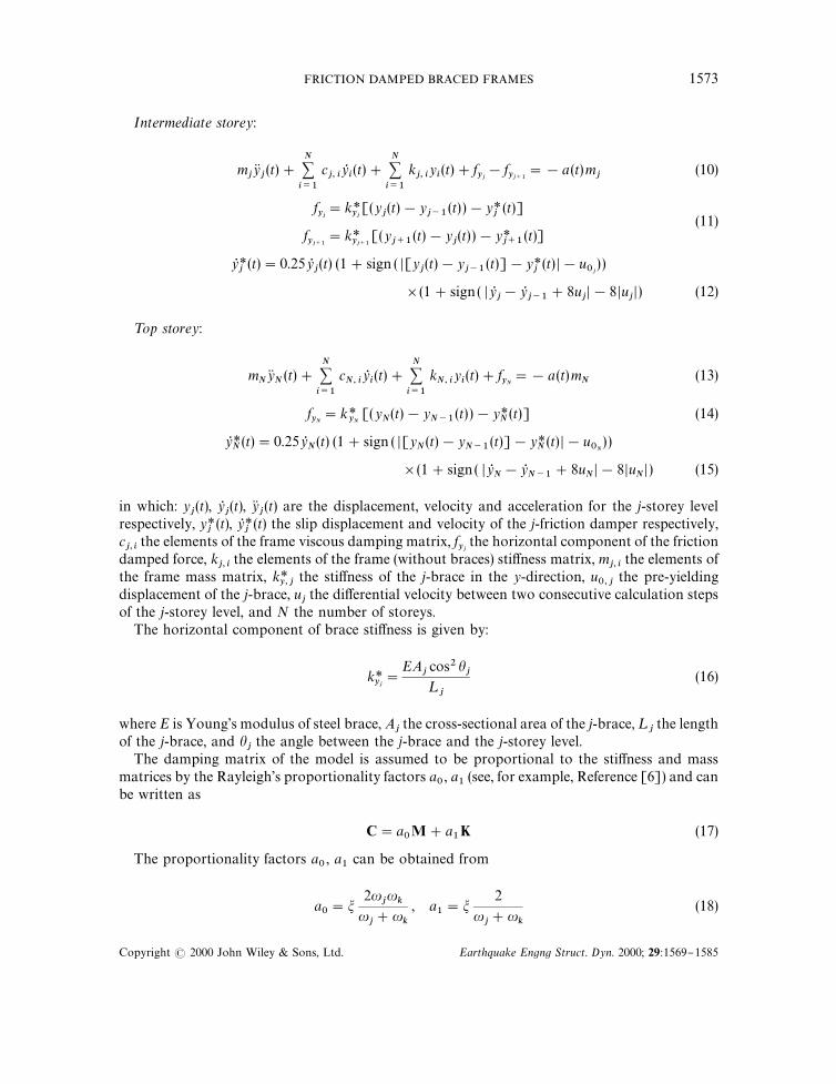
Intermediate storey:
mjyKj(t)#
N+i/1
cj, i
yRi(t)#
N+i/1
kj, i
yi(t)#f
yj!f
yj`1"!a (t)m
j(10)
fyj"k*
yj[(y
j(t)!y
j~1(t) )!y*
j(t)]
(11)fyj`1
"k*yj`1
[(yj`1
(t)!yj(t) )!y*
j`1(t)]
yR *j(t)"0.25yR
j(t) (1#sign ( D[y
j(t)!y
j~1(t)]!y*
j(t) D!u
0j) )
](1#sign ( DyRj!yR
j~1#8u
jD!8Du
jD) (12)
¹op storey:
mNyKN(t)#
N+i/1
cN, i
yRi(t)#
N+i/1
kN, i
yi(t)#f
yN"!a (t)m
N(13)
fyN"k*
yN[(y
N(t)!y
N~1(t) )!y*
N(t)] (14)
yR *N(t)"0.25yR
N(t) (1#sign ( D[y
N(t)!y
N~1(t)]!y*
N(t) D!u
0N) )
](1#sign ( DyRN!yR
N~1#8u
ND!8Du
ND ) (15)
in which: yj(t), yR
j(t), yK
j(t) are the displacement, velocity and acceleration for the j-storey level
respectively, y*j(t), yR *
j(t) the slip displacement and velocity of the j-friction damper respectively,
cj,i
the elements of the frame viscous damping matrix, fyj
the horizontal component of the frictiondamped force, k
j, ithe elements of the frame (without braces) sti!ness matrix, m
j, ithe elements of
the frame mass matrix, k*y, j
the sti!ness of the j-brace in the y-direction, u0, j
the pre-yieldingdisplacement of the j-brace, u
jthe di!erential velocity between two consecutive calculation steps
of the j-storey level, and N the number of storeys.The horizontal component of brace sti!ness is given by:
k*yj"
EAjcos2 h
j¸
j
(16)
where E is Young's modulus of steel brace, Ajthe cross-sectional area of the j-brace, ¸
jthe length
of the j-brace, and hjthe angle between the j-brace and the j-storey level.
The damping matrix of the model is assumed to be proportional to the sti!ness and massmatrices by the Rayleigh's proportionality factors a
0, a
1(see, for example, Reference [6]) and can
be written as
C"a0M#a
1K (17)
The proportionality factors a0, a
1can be obtained from
a0"m
2uju
ku
j#u
k
, a1"m
2
uj#u
k
(18)
FRICTION DAMPED BRACED FRAMES 1573
Copyright ( 2000 John Wiley & Sons, Ltd. Earthquake Engng Struct. Dyn. 2000; 29:1569}1585

where uj
and uk
are two chosen natural frequencies of the frame without braces, which aredetermined by solving the undamped eigenvalue equation
DK!u2M D"0 (19)
where u is the frequency and m is the assumed damping ratio for the two modes.The braces with friction dampers are signi"cantly non-linear. Compared with hysteretic
damping the e!ect of viscous damping is relatively small, and therefore viscous damping in thebraces has been neglected in the present formulation.
The proposed mathematical model of bi-linear hysteresis for MDOF systems, uses a newcontrol hysteresis loop function u
2(t), which simpli"es numerical calculations signi"cantly, and
reduces computer time.
3. DESIGN OF FRICTION DAMPERS
The design of friction dampers consists of evaluating the sti!ness of the braces and their slipelongations for a given set of constraints on interstorey drifts. This work uses equal drifts. Thus, atmaximum response (after slippage), the displaced shape of the structure will have attaineda straight line. Slip points are used to de"ne the elongations of the braces up to the brink ofslippage. The design approach has two main phases.
Phase 1 condenses the MDOF model of the structure with no braces to an equivalent SDOFmodel. A brace is designed according to an iterative optimization scheme and, thus, an equivalentnatural period of the SDOF model with a brace is achieved. This is the period that the MDOFwill be designed for in Phase 2.
The equivalent mass, sti!ness, and natural frequency of the SDOF model are calculated fromthe "rst mode behaviour of the basic frame structure (without braces) as
M1"/T
1M/
1(20)
K1"/T
1K/
1(21)
u1"S
K1
M1
(22)
The interstorey drifts are assumed equal for all storeys. The maximum allowable displacement,*!--, of the top of the structure for both the SDOF and MDOF models becomes
*!--"Nd!-- (23)
where N is the number of storeys, and d!-- the allowable interstorey drift.Moreover, it is assumed that all the friction dampers are activated simultaneously and the slip
elongations are the same for all the dampers. Thus, in the SDOF model the slip elongation, u0, is
taken as the sum of the slips of the MDOF model (see Figure 3). The slip elongation of the brace isgiven as
u0.!9
"
f4¸cos hEA
(24)
1574 R. LEVY E¹ A¸.
Copyright ( 2000 John Wiley & Sons, Ltd. Earthquake Engng Struct. Dyn. 2000; 29:1569}1585

Figure 3. Scheme of condensation from MDOF to SDOF.
where u0.!9
is the slip elongation of a single brace in the MDOF system, f4the slip force, ¸ the
length of the brace, and A the cross-sectional area of brace.The sti!ness of the braced SDOF, equivalent, structure is obtained iteratively using an&analysis/redesign' procedure in structural optimization [7] that takes the form
an`1"A*!--
*n Bpan (25)
where *n is the maximum response at the nth iteration, p is a convergence exponent (usually 0.5)and a"(K
1)/ (K
1&6--), the already de"ned secondary slope. The term &full ' refers to the frame
with its brace. The analysis is actually a non-linear one using the dynamic model (Equa-tion (1)). Finally, the period of the braced SDOF, equivalent, structure, is obtained from
¹&6--
"2nJM1/K
1&6--.
Most of the analytical methods to estimate the earthquake response to non-linear hystereticsystems are based on de"ning a viscously damped linear system whose maximum responseapproximates that of the non-linear hysteretic system. The equation of motion of the e!ectivelinear SDOF system is given by
yK (t)#2m%&&
u%&&
yR (t)#u2%&&
y (t)"!!a(t) (26)
where
u2%&&"
k%&&
M1
"A2n¹
%&&B2
(27)
The parameters k%&&
, u%&&
, ¹%&&
and m%&&
represent e!ective system quantities. Iwan and Gates [8]proposed a set of e!ective damping and natural period, m
%&&and ¹
%&&, which they obtained for
harmonic and random responses. This work uses e!ective values obtained according to their
FRICTION DAMPED BRACED FRAMES 1575
Copyright ( 2000 John Wiley & Sons, Ltd. Earthquake Engng Struct. Dyn. 2000; 29:1569}1585
average period and damping (APD) method. These are
¹%&&"¹
&6--
1
k C1#Jak2#(1!a)k!1
a!
1!a2a3@2
ln fD , k"*u0
(28)
where
f"2Ja[ak2#(1!a)k]#2ak#(1!a)
a#2Ja#1
and
m%&&"m
¹%
¹&6--
#
2
n1!a
k C1
aln (1!a#ak)#
1
1!aln A
1!ak
#aBD , k"*u0
(29)
Phase 2 consists of a two-stage iterative scheme that produces the brace sti!nesses and the slipelongations as the design converges to the period of phase 1.
At "rst, the MDOF model is in motion without slip, and therefore the full sti!ness of thestructure is assembled from both the sti!nesses of the frame elements and the sti!ness of thebraces. Then as one of the braces slips all the friction dampers are assumed to be activated, andthe sti!ness of the structure reduces to the sti!ness of the frame alone. At the completion of thedesign the dampers will have acted simultaneously.
The distribution of the non-linear friction forces, fy , in the damper is assumed to be propor-tional to the equivalent forces, fe , obtained for the same MDOF with viscoelastic dampers, i.e.
fyiJ f
%i. (30)
Moreover, at maximum response, this viscoelastic MDOF system should exhibit a displacedshape of a straight line for the originally de"ned equal drifts criterion. The following is theprocedure whereby the equivalence is obtained. The equation of motion of the frame structurewith linear devices can be presented as follows:
MyK (t)#Cy5 (t)#Ky(t)#f0e (t)"!a(t)Mi (31)
Here f0e (t) is the horizontal force vector of the equivalent viscoelastic dampers at #oor levelsand i is a vector with entries of 1.0. This force vector may be de"ned as
f0e (t)"Key (t)#Cey5 (t) (32)
in which the Ke and Ce are, respectively, the sti!ness and damping matrices for horizontaldisplacements of the diagonals at #oor levels.
1576 R. LEVY E¹ A¸.
Copyright ( 2000 John Wiley & Sons, Ltd. Earthquake Engng Struct. Dyn. 2000; 29:1569}1585

Evaluation of Ke
The sti!nesses of the braces can be obtained by assuming a desired "rst mode, u1, behaviour (in
this paper a straight line) for the equivalent MDOF system having viscoelastic dampers:
(K#Ke)u1"u2
%&&u
1(33)
The sti!ness matrix Ke can be presented in tri-diagonal matrix form as:
Ke"
k1%#k2
%!k2
%!k2
%k2%#k3
%!k3
%} } } !kn
%!kn
%kn%
Algebraic manipulations transform Equation (33) to:
u11
u11!u2
1} u2
1!u1
1u21!u3
1} } } un~1
1!un
1} un
1!un~1
1
k1%
k2%F
kn%
" K
u11
u21
un1
#u2%
u11
u21
un1
(34)
Equation (34) can now be written as:
Ake"b (35)
Because the sti!nesses, ke , cannot be negative the solution of Equation (35) is performed usingthe standard least squares approximation with non-negative variables, which is usually writtenas:
min EAke!bE22
s.t. ke*0. (36)
Evaluation of Ce
Following Equation (17) the equivalent viscous matrix may be taken as:
Ce"a0M#a
1(K#Ke) (37)
where:
Ca0
a1D"
2f%&&
uj,%&&
#uk,%&&
Cu
j,%&&u
k,%&&1 D
This paper uses j"1 and k"3.If the mass matrix, M, is taken as diagonal and the frame sti!ness matrix, K, is taken as
tri-diagonal the viscous matrix, Ce , becomes tri-diagonal and its terms are the viscous coe$cientsof the linear dampers in the braces. If the mass matrix, M and/or the sti!ness matrix, K are taken
FRICTION DAMPED BRACED FRAMES 1577
Copyright ( 2000 John Wiley & Sons, Ltd. Earthquake Engng Struct. Dyn. 2000; 29:1569}1585

as full matrices, the viscous matrix, Ce is a full matrix as well. The evaluation of the viscouscoe$cients, in this case, can be obtained using storey drift transformation in the followingmanner.
First a transformation matrix, T that transforms interstorey drifts to storey displacements isde"ned
y (t)"Td(t) (38)
with:
T"C1
1 1
F F }1 1 1 1 D
then the viscous damping matrix, Ce is transformed into C$e in the interstorey formulation of thegoverning Equations (31) using
C$e"TTCeT (39)
The viscous damping parameters of each brace can now be obtained using a fundamental ("rst)mode approach. This approach takes a full matrix C$e and transforms it into an approximatediagonal matrix by minimizing the di!erence in the viscous components of forces squared overthe time history (least square approximation). Now, if viscous components of forces are de"nedusing only the fundamental mode the following diagonal terms result:
ck%"
+jc$e,kj
*/j1
*/k1
"+j
ce,kj
*/kj1
(40)
where:
*/kj1"
*/j1
*/k1
; */j1"/
j1!/
(j~1)1; */
k1"/
k1!/
(k~1)1and /
0,1"0
For equal drifts the "rst mode of the brace is u1"[1/N , 2/N ,2 , N/N]T. The values of the
sti!nesses (from solution of Equation (36)) and the viscous dampers (Equation (40)) now de"nethe forces in the braces as:
fei"kk
e(y
i!y
i~1)#ck
e(yR
i!yR
i~1) (41)
The sti!ness of each brace is obtained as
k*yi"
fyi
u0i
J
f%i
u0i
(42)
1578 R. LEVY E¹ A¸.
Copyright ( 2000 John Wiley & Sons, Ltd. Earthquake Engng Struct. Dyn. 2000; 29:1569}1585

or in another form
k*yi"q
f%i
u0i
"qk**yi
(43)
where q is as yet an unknown proportionality coe$cient.The full sti!ness matrix of the structure can now be presented in the following form:
K&6--
"[K]#q Ck**y1
#k**y2
!k**y2
!k**y2
k**y3
#k**y2
!k**y3
} } } !k**yn
!k**yn
k**yn
D (44)
Following is the two-stage iterative procedure for the design of the braces and slip elongations.
Step 1: Choose u0i"u
0.!9and q"1.0.
Step 2: Calculate k**yi
from Equation (43). The values of f%i
in Equation (43) are obtained bysolving the system of Equations (7), (10) and (13) with each f
yireplaced by the
expression of Equation (41).Step 3: Redesign using
qn`1"A¹/
¹&6--Bpqn (45)
where ¹n is the period of the full i.e. braced structure, (Equation (44), for the currentparameters obtained for the "rst eigenvalue with K
&6--and M.
Step 4: Calculate u0i
from
u0i"
di
d.!9
u0.!9
(46)
where di"/
i1!/
(i~1)1and d
.!9"(/
i1!/
(i~1)1).!9
where /i1
is the element i of the"rst mode shape with K
&6--and M.
Step 5: Go to step 2 until convergence.
4. EXAMPLE
As an illustration of the proposed design methodology through energy dissipation, a 10-storeysteel frame shown in Figure 1(b) with friction dampers as energy dissipators was chosen. Analysisof the structure was performed using a computer program, which was written by the authors toaccommodate the dynamic model. The Runge}Kutta step-by-step integration was used to solvethe equations. The structure was assumed to have viscous damping, m"2 per cent, and thefriction dampers were assumed to behave as elastic}perfectly plastic connections (Figure 2).Di!erent earthquakes, even though of similar intensities, lead to widely varying responses, and
FRICTION DAMPED BRACED FRAMES 1579
Copyright ( 2000 John Wiley & Sons, Ltd. Earthquake Engng Struct. Dyn. 2000; 29:1569}1585
Figure 4. Storey displacement at instant of maximum response.
Table I. Slip elongation and sti!ness of the friction dampers.
Storey number Slip elongation Sti!ness k*yi
Friction force, fyi
u0
(cm) (ton/cm) (ton)
1 0.34 157.94 54.082 0.47 92.51 43.793 0.54 80.27 43.344 0.58 68.84 39.955 0.60 58.06 34.866 0.57 56.11 31.877 0.54 49.04 26.298 0.53 33.72 17.859 0.49 24.14 11.88
10 0.38 11.45 4.44
results based on a single record may not be conclusive. In this example only the NS component of1940 El Centro record, scaled to peak ground accelerations of 0.4g was used.
The mass and sti!ness matrices of the general basic structure without dampers are given in theAppendix.
Phase 1 of the design methodology yields a natural frequency for the equivalent SDOF frame(Equation (22) of u"2.23 rad/sec (or ¹"2.82 sec). The allowable interstorey d!--drift is assumedthe same for all storeys and is equal to 1.5 cm. The maximum allowable top storey displacement
1580 R. LEVY E¹ A¸.
Copyright ( 2000 John Wiley & Sons, Ltd. Earthquake Engng Struct. Dyn. 2000; 29:1569}1585

Figure 5. Response time history of roof.
becomes *!--"d!--]10"15 cm. The brace length l"6 m. The angle between the braces andstorey levels h"303. The horizontal component of the maximum allowable slip elongation ofeach brace is (Equation (24)) u
0.!9"f
yl cos 303/E"2350]600]0.87/2.10]106"0.6 cm. The
slip point for the &equivalent' SDOF is u0"0.6]10"6 cm. The participation factor !"1.28
was calculated for the "rst mode of the unbraced frame and used for both the friction dampedSDOF frame and the viscoelastic SDOF. Iterations according to Equation (25) yields a secondarysti!ness ratio of a"0.15 and a natural period of ¹
&6--"1.05 sec for the SDOF with the
&equivalent' brace. The e!ective natural period and damping from Equations (28) and (29) are:¹
%&&"1.88 sec and m
%&&"0.11 ton/sec2.
Phase 2 yields the following sti!ness and viscous damping parameters as obtained for theequivalent viscoelastic devices from Equations (36) and (40):
ke"[27.37, 17.71, 17.91, 16.49, 14.27, 13.38, 10.70, 6.35, 7.86, 0.00]T ton/cmce"[3.78, 3.71, 3.58, 3.37, 3.09, 2.75, 2.34, 1.85, 1.30, 0.69]T ton sec/cm
According to Equation (41) the forces in these devices become
fe"[80.89, 56.43, 52.25, 46.52, 40.05, 37.35, 31.54, 21.61, 14.77, 5.78]T ton
The slip elongations and sti!nesses of the braces which are calculated using Equations (43)}(46)are presented in Table I.
Figure 4 presents roof displacements of the structure at the instant of maximum response.Figure 5 shows the time-history response for the MDOF structure with friction and equivalent
FRICTION DAMPED BRACED FRAMES 1581
Copyright ( 2000 John Wiley & Sons, Ltd. Earthquake Engng Struct. Dyn. 2000; 29:1569}1585

Figure 6. Deviation in drift from target displacements: (solid line) at peak displacements;(dotted line) at maximum roof displacements.
viscoelastic dampers. Figure 6 shows the maximum interstorey drift deviations from the originalequal drift design objective for the MDOF with friction dampers. The solid lines describe the driftdeviations throughout the history of the earthquake whereas the dotted line describes them at theinstant of maximum roof response displacement.
Figure 7 shows the cumulative dissipation of friction energy in the friction dampers. Thecalculation of the dissipated energy was performed using
EDi"f
yi Pt
D y* Ddt (47)
where EDi
is the dissipated energy in the ith friction damper.Figure 8 illustrates the importance of slip elongation design according to the behaviour
of the structure. This "gure presents the time-history response of the structure whenthe friction forces in the dampers are proportional to the forces of the e!ective visco-elastic dampers for two cases having the same friction forces. One case (solid line) hasdampers designed with optimal slip elongations (results of Table I) and the other case,(dotted line) has dampers with slip elongations that are taken as u
.!9"0.6 cm everywhere
(Table II).
1582 R. LEVY E¹ A¸.
Copyright ( 2000 John Wiley & Sons, Ltd. Earthquake Engng Struct. Dyn. 2000; 29:1569}1585

Figure 7. Accumulative dissipated energy.
Figure 8. Response time histories*optimum set of slip elongations vs. equal slip elongations everywhere.
FRICTION DAMPED BRACED FRAMES 1583
Copyright ( 2000 John Wiley & Sons, Ltd. Earthquake Engng Struct. Dyn. 2000; 29:1569}1585
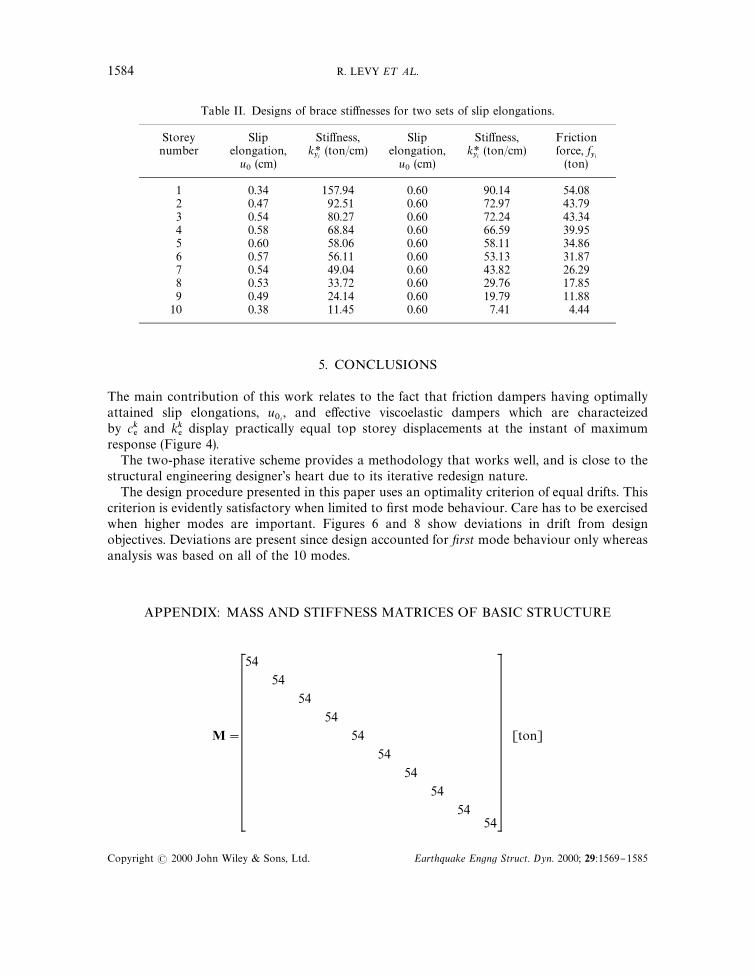
Table II. Designs of brace sti!nesses for two sets of slip elongations.
Storey Slip Sti!ness, Slip Sti!ness, Frictionnumber elongation, k*
yi(ton/cm) elongation, k*
yi(ton/cm) force, f
yiu0
(cm) u0
(cm) (ton)
1 0.34 157.94 0.60 90.14 54.082 0.47 92.51 0.60 72.97 43.793 0.54 80.27 0.60 72.24 43.344 0.58 68.84 0.60 66.59 39.955 0.60 58.06 0.60 58.11 34.866 0.57 56.11 0.60 53.13 31.877 0.54 49.04 0.60 43.82 26.298 0.53 33.72 0.60 29.76 17.859 0.49 24.14 0.60 19.79 11.88
10 0.38 11.45 0.60 7.41 4.44
5. CONCLUSIONS
The main contribution of this work relates to the fact that friction dampers having optimallyattained slip elongations, u
0i, and e!ective viscoelastic dampers which are characteized
by ck%
and kk%
display practically equal top storey displacements at the instant of maximumresponse (Figure 4).
The two-phase iterative scheme provides a methodology that works well, and is close to thestructural engineering designer's heart due to its iterative redesign nature.
The design procedure presented in this paper uses an optimality criterion of equal drifts. Thiscriterion is evidently satisfactory when limited to "rst mode behaviour. Care has to be exercisedwhen higher modes are important. Figures 6 and 8 show deviations in drift from designobjectives. Deviations are present since design accounted for ,rst mode behaviour only whereasanalysis was based on all of the 10 modes.
APPENDIX: MASS AND STIFFNESS MATRICES OF BASIC STRUCTURE
M"
54
54
54
54
54
54
54
54
5454
[ton]
1584 R. LEVY E¹ A¸.
Copyright ( 2000 John Wiley & Sons, Ltd. Earthquake Engng Struct. Dyn. 2000; 29:1569}1585

K"
141.66 !121.59 38.41 !7.19 1.43 !0.19 0.15 !0.52 0.73
!121.59 182.01 !121.25 37.57 !7.02 1.35 !0.45 0.52 !0.72
38.41 !121.25 171.99 !112.91 33.85 !5.92 1.02 !0.26 0.34
!7.19 37.57 !112.91 160.38 !105.33 31.53 !6.26 1.58 !0.57
1.43 !7.02 33.85 !105.33 151.05 !99.40 31.22 !6.93 1.58
!0.19 1.35 !5.92 31.53 !99.40 143.54 !94.79 28.53 !5.41
0.15 !0.45 1.02 !6.26 31.22 !94.79 136.79 !89.03 24.92
!0.52 0.52 !0.26 1.58 !6.93 28.53 !89.03 125.78 !77.18
0.73 !0.72 0.34 !0.57 1.58 !5.41 24.92 !77.18 100.63
!0.36
0.41
!0.23
0.23
!0.28
0.83
!3.60
17.35
!44.09
!0.36 !0.41 !0.23 0.23 !0.28 0.83 !3.60 17.35 !44.09 29.61
(ton/cm)
REFERENCES
1. Pall AS, Marsh C. Seismic response of friction damped braced frames. Journal of Structural Engineering, ASCE 1982;108(9): 1313}1323.
2. Fitzgerald TF et al. Slotted bolted connections in a seismic design for concentricity braced connections. EarthquakeSpectra 1989; 5(2): 383}391.
3. Grigorian CE, Yang TS, Popov EP. Slotted bolted connection energy dissipators. Report of National ScienceFoundation, University of California, Berkeley, 1992.
4. Popov EP, Yang TS, Grigorian CE. New directions in structural seismic designs. Earthquake Spectra 1993; 9(4):845}875.
5. Colajanni P, Papia M. Hysteretic characterization of friction-damped braced frames. Journal of Structural Engineering,ASCE 1997; 123(8): 1020}1028.
6. Clough RW, Penzien J. Dynamic of Structures. McGraw-Hill: New York, 1993.7. Spillers WR. Iterative Structural Design. North-Holland; Amsterdam, 1975.8. Iwan WD, Gates NC. Estimating earthquake response of simple hysteretic structures. Journal of the Engineering
Mechanics Division 1979; 105 (EM3).
FRICTION DAMPED BRACED FRAMES 1585
Copyright ( 2000 John Wiley & Sons, Ltd. Earthquake Engng Struct. Dyn. 2000; 29:1569}1585