selecting vantage points for an autonomous quadcopter ... · selecting vantage points for an...
TRANSCRIPT
Selecting Vantage Points for an Autonomous Quadcopter Videographer
Rey CoaguilaGoogle
Mountain View, [email protected]
Gita SukthankarUniversity of Central Florida
Orlando, [email protected]
Rahul SukthankarGoogle
Mountain View, [email protected]
Abstract
A good human videographer is adept at selecting thebest vantage points from which to film a subject. Theaim of our research is to create an autonomous quad-copter that is similarly skilled at capturing good pho-tographs of a moving subject. Due to their small sizeand mobility, quadcopters are well-suited to act asvideographers and are capable of shooting from loca-tions that are unreachable for a human. This paper eval-uates the performance of two vantage point selectionstrategies: 1) a reactive controller that tracks the sub-ject’s head pose and 2) combining the reactive systemwith a POMDP planner that considers the target’s move-ment intentions. Incorporating a POMDP planner intothe system results in more stable footage and less quad-copter motion.
IntroductionThe “flying selfie bot” has emerged as an important commer-cial application of quadcopters, due to the voracious con-sumer demand for high quality photos and videos to share onsocial media platforms (Schneider 2015). Although most ef-forts target outdoor and sports photography, quadcopters canbe valuable for indoor photographers as well. For instance,Srikanth et al. (2014) demonstrated the utility of quadcoptersat providing rim illumination of a moving subject.
To make the best use out of its limited battery life, an au-tonomous system must solve the same optimization problemfaced by a lazy videographer who seeks to produce a steadystream of good footage, with minimal effort, commemorat-ing the event. A practiced human photographer is skilled atfinding the best vantage points from which to capture thescene. This paper tackles a constrained version of the van-tage point selection problem in which the aim is to produce astream of high-quality frontal photos of a single moving sub-ject over a short time period with minimal quadcopter mo-tion. We evaluate two approaches implemented on a ParrotAR.Drone: 1) a reactive system that tracks the subject’s headpose using PD control and 2) coupling the reactive systemwith a movement policy produced by a POMDP (PartiallyObservable Markov Decision Process) solver that considersthe subject’s movement intentions. Head pose is estimated in
Copyright c© 2016, Association for the Advancement of ArtificialIntelligence (www.aaai.org). All rights reserved.
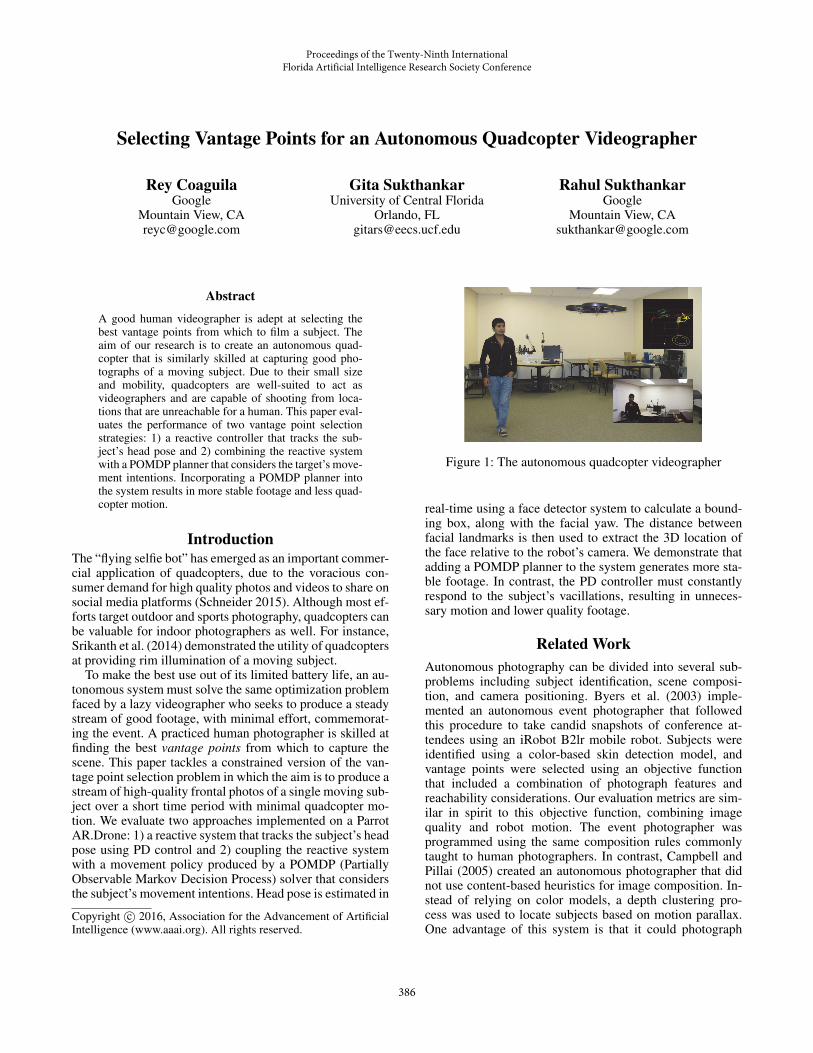
Figure 1: The autonomous quadcopter videographer
real-time using a face detector system to calculate a bound-ing box, along with the facial yaw. The distance betweenfacial landmarks is then used to extract the 3D location ofthe face relative to the robot’s camera. We demonstrate thatadding a POMDP planner to the system generates more sta-ble footage. In contrast, the PD controller must constantlyrespond to the subject’s vacillations, resulting in unneces-sary motion and lower quality footage.
Related WorkAutonomous photography can be divided into several sub-problems including subject identification, scene composi-tion, and camera positioning. Byers et al. (2003) imple-mented an autonomous event photographer that followedthis procedure to take candid snapshots of conference at-tendees using an iRobot B2lr mobile robot. Subjects wereidentified using a color-based skin detection model, andvantage points were selected using an objective functionthat included a combination of photograph features andreachability considerations. Our evaluation metrics are sim-ilar in spirit to this objective function, combining imagequality and robot motion. The event photographer wasprogrammed using the same composition rules commonlytaught to human photographers. In contrast, Campbell andPillai (2005) created an autonomous photographer that didnot use content-based heuristics for image composition. In-stead of relying on color models, a depth clustering pro-cess was used to locate subjects based on motion parallax.One advantage of this system is that it could photograph
Proceedings of the Twenty-Ninth International Florida Artificial Intelligence Research Society Conference
386

non-human subjects, assuming that they posed for the cam-era. Since our goal is to produce real-time streaming videofootage of a single rapidly-moving subject, our quadcoptervideographer does not discard frames or crop images, unlikethese systems.
The aim of the related FollowMe system was to do hands-free filming with a quadcopter; for this application, Naseeret al. (2013) demonstrated autonomous human-following us-ing an on-board depth camera. The FollowMe human trackerrecovers full body pose from warped depth images, whichare also used for gesture recognition. Our proposed sys-tem relies on head pose estimation; the human’s movementintentions are anticipated using a POMDP, rather than agesture-based command system.
Our work differs from existing work on tracking humansor vehicles using UAVs (Teuliere, Eck, and Marchand 2011)in that our focus is on filming a subject from a specific(frontal) vantage point rather than simply maintaining a sub-ject in the camera’s field of view. The problem is more chal-lenging because a small change in the subject’s facing canrequire large quadcopter motions and thus requires morecomplex motion planning.
MethodFigure 2 shows our system architecture. We use an un-modified, commercially available quadcopter, the ParrotAR.Drone, which comes equipped with two cameras (front-facing and downward-facing), a 3-axis gyroscope and ac-celerometer, and an ultrasound altimeter. The robot calcu-lates its horizontal speed using vision algorithms (Bristeau etal. 2011) that process data from the downward-facing cam-era. This information, along with the ultrasound and gyro-scope measurements, are sent over WiFi to our PC. In orderto command the robot, the quadcopter also receives controlmessages over WiFi consisting of a desired 3D velocity andthe angular yaw velocity, all specified with respect to therobot’s current frame of reference. The robot’s onboard soft-ware translates these commands into rotor speeds to achievethe desired pose.
We employ the ROS framework to handle the communi-cation between the quadcopter and the different parts of oursystem. At a high level, the localizer node tracks the currentstate of the quadcopter along with the subject’s location andrelative orientation, while the controller node selects van-tage points to best capture frontal images of the subject asit moves and generates the appropriate motion commands.Note that a small head turn from the subject can require thequadcopter to sweep in a wide arc in order to photograph thesubject from a frontal vantage point.
The face localizer sub-module processes the imagestream from the quadcopter’s front-facing camera to detectfaces. If detected, the face’s yaw and 3D location are com-puted and sent to the publisher, which transforms the detec-tion from image coordinates to the robot’s frame of refer-ence, using the gyroscope data.
The planner sub-module calculates a desired robot lo-cation based either on a simple reactive plan (i.e., servo-ing to maintain a frontal vantage point) or a more complex
Figure 2: System architecture
(a) (b) (c) (d)
Figure 3: Recovering subject’s head orientation: (a) feedfrom front-facing quadcopter camera (b) landmarks detectedby the face alignment process (c) ratios between the fivelandmarks that determine head orientation. Our method esti-mates that subject is facing away at a relative yaw of 29◦(d).
POMDP policy. The PD controller generates the commandsto drive the quadcopter to the desired point.
Estimating subject’s head orientation and 3DlocationTo detect the subject’s face in the feed obtained from thefront-facing camera, we employ a fast detector based on therecent work on max-margin object detector (King 2015),which uses Histograms of Oriented Gradient (Dalal andTriggs 2005) (HOG) features in conjunction with struc-tural SVMs, as made available in the Dlib open-source li-brary (King 2009).
Given the bounding box of a detected face, we use the“millisecond face alignment” method recently proposed byKazemi & Sullivan (2014) to recover the locations of fivekey landmarks on the subject’s face: the far corners of theeyes and mouth, and the tip of the nose. The method usesregression trees to localize landmarks in real time and weemploy the implementation in Dlib (King 2009) that waspretrained on the 300-W faces in-the-wild dataset (Sagonaset al. 2013) without additional training.
With the landmarks located, we calculate the subjectface’s orientation (relative to the front-facing camera) us-ing the geometric method by Gee & Cipolla (1994), whichrequires only the ratios of distances between certain faciallandmarks to be known. While this method could recoverthe tilt and yaw of the face, we focus only on the subject’s
387

yaw since this dominates the out-of-plane rotation and thusthe selection of suitable vantage points. Figure 3 shows anexample of the resulting estimate of the pose.
Localizer Node: Publisher Sub-ModuleThe detected location and pose of the face (obtained with theprevious method) are calculated with respect to the camera’sframe of reference. However, this needs to be transformed tothe robot’s frame of reference before computing the controlcommand. Also, since the quadcopter is tilted every time itmoves horizontally, the location with respect to the cameramay not be accurate. To account for this, we correct the cal-culated location by the roll and pitch angles that are providedby the quadcopter’s gyroscope.
While straightforward in concept, this process is compli-cated by the fact that the image stream and the navigationdata are received at different rates and with different delays.We address this by executing an additional step to match theface location estimate to the most accurate quadcopter lo-cation available, inspired by the approach used by Engel etal. (2012). To do this, we maintain a queue of the estimatedquadcopter locations over the last second, obtained from thenavigation data, and when the face localizer returns an esti-mate of the face with respect to the camera, we use its times-tamp to match the best available estimate of where the robotwas when the picture was taken.
We also maintain an estimate of the drone’s position withrespect to its initial location. This is performed by integrat-ing the (noisy) navigation information, which can result inan inaccurate global estimate of the quadcopter’s location.To mitigate the effects of this noise on planning for vantagepoint selection, the planner operates in the current ratherthan the global reference frame. The complete state, con-sisting of location and 2D orientation (yaw) information forthe robot and subject (face) is summarized as:
(xr, yr, zr,Ψr, xf , yf , zf ,Ψf ).
Planning Problem - Reactive and POMDP modelOnce the pose of the human face is computed, our systemmust decide on the actions to be executed by the quad-copter in order to capture good video sequences. The subjecthas the freedom to move anywhere so a straightforward ap-proach is to maintain the quadcopter at a given position withrespect to the detected face. This is implemented directly us-ing a reactive model that calculates the goal location in eachframe.
Our second approach minimizes the motion of the quad-copter in the case when the subject is shifting slightlyaround the same central location. This approach was imple-mented with a Partially Observable Markov Decision Pro-cess (POMDP) (Kurniawati, Hsu, and Lee 2008) plannerthat considers the ‘intention’ of the human which can be ei-ther to change pose or to preserve it. With this information,the controller decides when to change its goal location (sim-ilar to the reactive behavior) and when to remain in place.
Reactive Behavior The goal location, which the con-troller will try to maintain even when the subject is moving,is defined as a point, centered in front of the subject’s face.
Figure 4: Reactive Behavior: The goal location is calculatedas dfront meters in front of the person. The height of the goalis dheight meters above the location of the eyes.
This is a desirable vantage point from which the quadcoptercan obtain frontal photos. This point is determined by twovariables:• dfront: the frontal distance between the goal location and
the subject face.• dheight: the altitude of the robot with respect to the eyes
of the detected face. A value of dheight = 0 will maintainthe robot at the same level as the eyes of the subject.
The reactive behavior tries to maintain the robot in the goallocation, facing towards the human. In order to do this, a PDcontroller calculates the specific required commands. Forthe yaw command, an additional consideration is that therobot should be facing the human at all time (to avoid losingit from its sight). This can be seen in Figure 4, where thecommand for the robot is to rotate towards the left, althoughat the final goal location it will be rotated towards the right.
The simplicity of the reactive behavior allows for fasterreaction times when the person starts moving, e.g., walk-ing around a room or turning, but the responsiveness comesat a price. Not only is the resulting footage jerkier due toexcessive quadcopter motion but it is also possible for thequadcopter to be frequently out of position when the subjectturns away and then back, because it responds immediately(with large motions) to small changes in head orientation.
POMDP Planner Behavior The POMDP model attemptsto be more judicious in its selection of vantage points byavoiding unnecessary quadcopter motion. A key observationis that a subject may make many small motions near a loca-tion punctuated by occasional larger motions between loca-tions. To model this, we predict the intention of the subject(either maintaining or changing pose with respect to quad-copter position) and learn a “lazier” controller that executessignificant quadcopter motion only when merited.
More specifically, the POMDP quadcopter world has thefollowing partially observable variables:• loc: This represents the location of the subject, modeled as
the distance from the goal, and discretized into three vari-ables: l1, l2 and l3 (see Figure 5a). At each planning step,the goal location is calculated as dfront meters in front of
388

(a) Location model (b) Yaw model
Figure 5: POMDP quadcopter world: the location is calcu-lated by discretizing the distance from the goal, and the yawis calculated by discretizing the yaw between -90◦and 90◦.
the quadcopter. If the distance between this goal (consid-ering only the x and y directions and not the height) andthe subject is smaller than r1, then the value for loc shouldbe l1. If it is between r1 and r2, its value should be l2. Ifit is larger than r2, it should be l3.
• yaw: The yaw is defined as the angle of the subject’s facewith respect to the quadcopter’s front-facing camera. Anangle of zero would mean that the human is facing paral-lel to the camera (see Figure 5b). These readings are dis-cretized into 5 variables y1, . . . , y5 defined by the limitingangles −α2, −α1, α1 and α2 (α1 < α2).
• lint: Represents the “location intention” of the human tomove away from its location or not. It can have the valuesmove or keep.
• yint: Represents the intention of the human to rotate itsmain focus point (the yaw direction). It can have the val-ues front, rotate left, and rotate right.
In each time step, the POMDP planner receives a noisy read-ing of the location and yaw. This observation is used to up-date the belief about the current state including the intentionsthat are not directly observed. For this, we model the tran-sition probabilities as shown in Figure 6. In our model, thesubject maintains its location and yaw direction around thesafe zones (mostly in l1 and y3, but occasionally moving andreturning from l2, y2 and y4) when the intentions are lint =keep and yint = front. These intentions may change over timecausing the human to move away (states l3, y1, and y5). Thiswas pre-defined in the model by setting the probabilities ofthe subject changing locations higher or lower depending onthe intention, and also setting probabilities for the intentionitself to change.
At each planning step, the robot may execute two differentactions: do nothing or correct. The former avoids sendingany command to the quadcopter, and the latter calculates anew goal using the same steps as in the reactive behavior andthen executes motion commands to achieve it.
We modeled the rewards in the POMDP problem such that
Figure 6: POMDP transition model
the do nothing action is preferred when the subjects’ inten-tion is to maintain its pose and its yaw direction. On the otherhand, the correct action is preferred when the robot locationand yaw are in the extremes (l3, y1 and y5) or when the in-tention has changed, such as when the robot remains in themiddle zone too long (l2, y2 or y4).
Finally, in order to connect the planner to the real timesystem, the POMDP is first solved offline using the SAR-SOP algorithm (Kurniawati, Hsu, and Lee 2008) to ob-tain a policy. Then, during the execution, the POMDP con-troller calculates the best action according to the policy byobserving and updating the world state each 0.5 seconds.The resulting action is executed for the following time step.Also, every time the correct action was selected, the con-troller maintains this action for three seconds to complete afull correction rather than a partial movement. The result-ing POMDP controller exhibits the expected behavior: shortmovements of the human do not affect the goal of the quad-copter, so no commands are given, but bigger human move-ments trigger a corresponding move from the robot. For ex-ample, when a human is moving around in the l1 area, therobot will not move, but if he suddenly moves to the l3 area,it will move immediately. If the human moves to the l2 areaand stays there, the robot will not move immediately, but af-ter some time, the intention belief updates and it follows thehuman.
PD ControllerWhen the goal is calculated (and in the POMDP case, whenthe controller decides to change it), some commands need tobe given to move the quadcopter. These commands are cal-culated with an underlying PD controller that manages thecommands in the x-direction, y-direction, z-direction, andyaw independently. Since the commands need to be givenwith respect to the frame of reference of the quadcopter, theerror (distance to the goal and required yaw rotation) is firsttransformed to this frame of reference.
389

In order to get the derivative component of the PD con-troller, we use the velocities reported from the navigationdata (in the x and y direction). The yaw and height compo-nents do not need a derivative term, so only the proportionalerror is used in this case.
ResultsIn order to test our method, we executed several runs consist-ing of the controller commanding the quadcopter in a roomwith a moving subject.1 The size of the room was 7.5 by 4meters, with a height of 2.7 meters. We consider three typesof runs, characterized by the speed of the subject’s move-ment:• Scenario Type 1 - Slow Motion: In this case, the subject
maintains his position for periods of 15 to 20 seconds,executing short and slow translations (less than 1 meter)and rotations in between.
• Scenario Type 2 - Medium Motion: The subject main-tains his position for short periods of time, but now mayexecute small movements and rotations while doing so.The translations in between are longer (2 to 3 meters) andfaster.
• Scenario Type 3 - Fast Motion: The human does not, ingeneral, maintain position. He moves around and rotateshis face constantly with higher speed. Occasionally thesubject will remain in certain locations for a longer periodof time.The length of each run is exactly five minutes, measured
from when the controller switches to an autonomous behav-ior. The goal of the quadcopter is to be positioned 1.6 metersin front of the human, and at the same height as the eyes. Forthe POMDP planner case, the values for r1, r2, α1, α2 are0.4 meters, 0.6 meters, 15◦, and 40◦respectively.
Two categories of metrics were obtained from each run.The first includes command-related metrics that measure themagnitude of the movements the quadcopter executed overtime:• Total Commands x/y/z: the sum of the absolute values of
the linear velocity commands in three dimensions givento the quadcopter during a single run.
• Total Commands Yaw: the sum of the absolute values ofthe rotation commands (yaw) given to the quadcopter dur-ing a single run.The second includes the face-quality metrics, obtained by
analyzing the video recorded by the quadcopter:• Face Size Error: This metric measures the difference in
the size of the face in different frames, with respect to thedesired size. The desired size is calculated as the mode ofthe detected face rectangles in the runs with slow motion.This area represents the size we would expect to see whenthe robot is precisely at the goal distance. Then, for eachframe, we detect the face and calculate the ratio of its areavs. the desired area. If the ratio is smaller than one, weuse its inverse. This ratio then represents how differentthe area is with respect to the desired one. The total errorfor a run is the average ratio over all frames.
1A video of the system is available at:https://youtu.be/s6WJ6SaLZ1k.
302.8REACTIVESLOW
202.0POMDP
275.4REACTIVEMEDIUM
220.2POMDP
364.6REACTIVEFAST
230.0POMDP
0 400
(a) Average Total Commands (x/y/z)
501.9REACTIVESLOW
567.9POMDP
853.4REACTIVEMEDIUM
480.7POMDP
1170.4REACTIVEFAST
748.5POMDP
0 1300
(b) Average Total Commands (yaw)
Figure 7: Total commands executed by the controllers underdifferent scenarios. Smaller values indicate that the quad-copter moved less, resulting in more stable movies.
• Face Location Error: This corresponds to the average ab-solute value of the distance between the face (i.e., the cen-ter of the detection rectangle) and the frame center in pix-els.
• Face yaw: Average absolute value of the yaw, where zerorepresents a face that is looking straight at the camera.As shown in Figure 7, the POMDP controller generally
commands less quadcopter motion in comparison to the re-active behavior. As a result, the videos obtained when us-ing the POMDP planner are more stable and do not shiftas much. However, the tradeoff is that the subject may becloser or farther than the desired distance for short periodsof time. Figure 8a shows that the face size error is slightlygreater with the POMDP controller. This occurs because thePOMDP waits longer while determining the subject’s inten-tion before executing actions.
Figure 8b shows the error in location of the face, mea-sured in pixels from the center of the image. The POMDPcontroller exhibits a smaller error for the medium and fastscenarios. This occurs because the subject may be fartherthan the goal, hence any horizontal movement correspondsto a smaller movement in the center of the detected face.Thus, even though we are allowing the subject to move fur-ther before reacting, the face will in average be closer to thecenter of the frame in comparison to the reactive behavior.
Finally, Figure 8c shows the error in the yaw, measured asthe difference in the angle of the observed face vs. a frontalface (looking directly at the quadcopter). The POMDP con-troller achieves better results in the medium and fast scenar-ios. By oscillating constantly while trying to maintain itselfin front of the subject, the reactive behavior creates situa-
390

1.4REACTIVESLOW
1.8POMDP
1.6REACTIVEMEDIUM
2.0POMDP
1.7REACTIVEFAST
1.9POMDP
0 2
(a) Face Size Error (size difference ratio)
97.6REACTIVESLOW
116.9POMDP
136.1REACTIVEMEDIUM
110.4POMDP
174.1REACTIVEFAST
127.9POMDP
0 200
(b) Face Location Error (pixels)
9.5REACTIVESLOW
10.1POMDP
12.9REACTIVEMEDIUM
10.0POMDP
14.4REACTIVEFAST
11.0POMDP
0 16
(c) Face Yaw Error (degrees)
Figure 8: Face quality metrics measured as the average dif-ference vs. the ideal size, location (the center of the image),and a frontal looking face.
tions where the subject’s head pose is worse. On the otherhand, the POMDP filters small changes in the yaw so theaverage error is smaller.
Conclusion and Future WorkThis paper describes an autonomous quadcopter videogra-pher that captures frontal video of the subject. Our solutionprimarily employs monocular information, which is pro-cessed to estimate the subject’s facing. We evaluate the per-formance of two vantage point selection strategies: 1) a PDcontroller that tracks the subject’s head pose and 2) combin-ing the reactive system with a POMDP planner that con-siders the subject’s movement intentions. The POMDP isable to filter short motions and reacts only when the humanmoves farther or rotates more. As a result, this controllerexecutes less motion, thus obtaining more stable video se-quences than the PD controller alone. The ability to cap-ture stable video footage is particularly important for quad-copters used by professional photographers; this is often
achieved by adding a gimbaling system, which adds bothweight and expense. The POMDP can improve the aestheticquality of the video in ways that a gimbaling system can-not by anticipating the subjects’ rotation and filming from afrontal viewpoint; this differs from commercial quadcoptersolutions that simply follow the subject. In future work, weplan to explore more complex image composition policies toshoot group videos. By introducing multi-frame evaluationmetrics that consider events rather than static scenes, we canpotentially improve the narrative structure of the video inaddition to the visual aesthetics.
ReferencesBristeau, P.-J.; Callou, F.; Vissiere, D.; Petit, N.; et al. 2011.The navigation and control technology inside the AR.Dronemicro UAV. In World Congress of the International Federa-tion of Automatic Control, volume 18, 1477–1484.Byers, Z.; Dixon, M.; Goodier, K.; Grimm, C. M.; andSmart, W. D. 2003. An autonomous robot photographer.In IROS, 2636–2641.Campbell, J., and Pillai, P. 2005. Leveraging limited au-tonomous mobility to frame attractive group photos. InICRA, 3396–3401.Dalal, N., and Triggs, B. 2005. Histograms of oriented gra-dients for human detection. In CVPR, 886–893.Engel, J.; Sturm, J.; and Cremers, D. 2012. Camera-basednavigation of a low-cost quadrocopter. In IROS, 2815–2821.Gee, A., and Cipolla, R. 1994. Determining the gaze of facesin images. Image and Vision Computing 12(10):639–647.Kazemi, V., and Sullivan, J. 2014. One millisecond facealignment with an ensemble of regression trees. In CVPR,1867–1874.King, D. E. 2009. Dlib-ml: A machine learning toolkit.Journal of Machine Learning Research 10:1755–1758.King, D. E. 2015. Max-margin object detection.arXiv:1502.00046.Kurniawati, H.; Hsu, D.; and Lee, W. S. 2008. SARSOP: Ef-ficient point-based POMDP planning by approximating op-timally reachable belief spaces. In Robotics: Science andSystems.Naseer, T.; Sturm, J.; and Cremers, D. 2013. FollowMe: Per-son following and gesture recognition with a quadrocopter.In IROS, 624–630.Sagonas, C.; Tzimiropoulos, G.; Zafeiriou, S.; and Pantic,M. 2013. 300 faces in-the-wild challenge: The first faciallandmark localization challenge. In International Confer-ence on Computer Vision Workshops, 397–403.Schneider, D. 2015. Flying selfie bots. IEEE Spectrum52(1):49–51.Srikanth, M.; Bala, K.; and Durand, F. 2014. Computationalrim illumination with aerial robots. In Proceedings of theWorkshop on Computational Aesthetics, 57–66.Teuliere, C.; Eck, L.; and Marchand, E. 2011. Chasing amoving target from a flying UAV. In IROS.
391