selector hub assemblies - schaeffler group · higher performance engines, ... components design of...
TRANSCRIPT

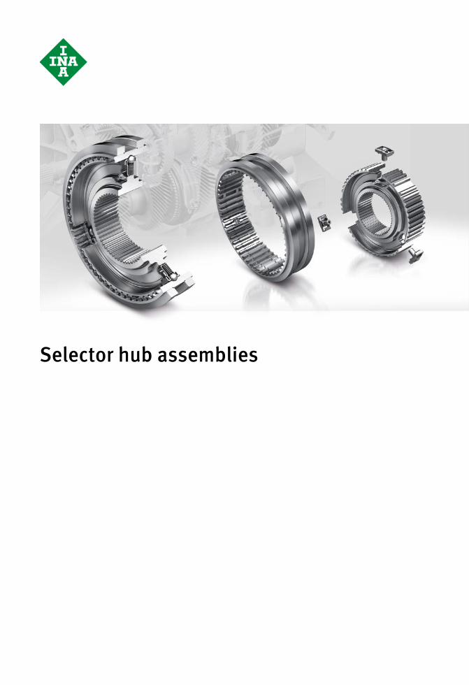
Selector Hub Assemblies


Foreword
As a development partner to the automotive industry, Schaeffler Group Automotive develops and manufactures components and sys-tems that take account of requirements for increased performance density and the reduction of factors such as mounting work and overall costs.Higher performance engines, increased torque loads on trans-missions and the demand for reduced design envelope are just a few of the defining conditions.Selector hub assemblies from Schaeffler are compact, ready-to-fit units for synchronization, comprising a selector hub, selector sleeve and detent struts. They facilitate gearshift in manual and dual clutch transmissions and transmit the torque from the transmission shaft to the engaged gear. The Schaeffler product range of synchronization components offers a large number of variants and facilitates flexible possibilities for solutions, even in the case of new requirements.This TPI contains, in addition to a description of the product characteristics of selector hub assemblies, a presentation of the development tools used for design, simulation and testing.A checklist is provided in order to support you as a customer in com-piling the technical data that are required in order to process your enquiry in an effective manner. First, the chapter Synchronization explains the underlying principles and presents the necessary components.
Further information Comprehensive description of the detent struts fitted in selector hub assemblies:■ TPI 178, Detent Struts ARRES – Synchronization of manual
transmissions.

2 TPI 125 Schaeffler Technologies

Schaeffler Technologies TPI 125 3
Page
Contents
Synchronization.................................................................... 4
Selector hub assemblies....................................................... 12
AppendixChecklist

SynchronizationSynchronization systemsComponentsSingle cone synchronizersMultiple cone synchronizers

Schaeffler Technologies TPI 125 5
Page
Synchronization
Synchronization systems Function ............................................................................... 6
Requirements ....................................................................... 6
Systems ............................................................................... 6
Components Design of a synchronization system....................................... 7
Selector hub ......................................................................... 7
Selector sleeve ..................................................................... 8
Detent struts......................................................................... 8
Synchro rings........................................................................ 9
Gear cone body..................................................................... 9
Gear wheel ........................................................................... 9
Single cone synchronizers Design.................................................................................. 10
Function ............................................................................... 10
Multiple cone synchronizers Design and function.............................................................. 11
Areas of application.............................................................. 11

6 TPI 125 Schaeffler Technologies
Synchronization systems
Synchronization is derived from the Greek syn (together) and chronos (time) and is defined as “ensuring the occurrence in unison of two events or processes”.
Function Synchronization systems in manual transmissions match the differ-ent speeds of the gear wheel to be engaged and the transmission shaft to each other.Following synchronization, a form fit connection is created between the gear wheel and transmission shaft by engaging the clutch.In order to ensure that synchronization occurs before clutching,a finely tuned blocking function is necessary.
Requirements The continuing increase in the performance capacity of engines and clutches is leading to significant increases in transmission torques and mass moments of inertia. This places ever-increasing demands on automotive manual transmissions and their components.As a result, it is generally no longer sufficient to optimize individual transmission components purely at the component level. What is required instead is solutions that are comprehensively oriented to the overall concept of the vehicle.For synchronization of a manual transmission, there is thus a need for products with characteristics such as compact design, optimized mass and smooth running with the highest functional reliability.In addition, gearshift force should be minimized and gearshift comfort improved.
Systems The state of the art in mechanical automotive manual transmissions comprizes synchronization systems based on a cone friction clutch, in the form of a blocking synchromesh.The distinction in blocking synchromeshes is between single cone synchronizers and multiple cone synchronizers, Figure 1.
� Single cone synchronizer� Multiple cone synchronizer
� Friction surfaces
Figure 1Single cone and multiple cone
synchronizers 0009
0A13
0009
0A13

Schaeffler Technologies TPI 125 7
Components
Structureof a synchronization system
A synchronization system comprizes the following components:■ 1 selector hub■ 1 selector sleeve■ 3 or more detent struts for presynchronization■ 2 or more synchro rings, with friction linings■ 2 gear cone bodies■ 2 gear wheels.The structure of a synchronization system can be shown usingthe example of a single cone synchronizer, Figure 1.
Selector hub The selector hub has a form fit connection with the transmission shaft. Its external teeth guide the selector sleeve. When engaged, the external teeth transmit torque between the selector hub andthe selector sleeve.The outside diameter of the selector hub has recesses which carry the detent struts for presynchronization. It gives form fit indexing of the detent struts and synchro outer rings.As a result, these components are brought into their direction of rotation by the selector hub. Depending on the design, synchro inner rings in multiple cone synchronizers system are also indexed.
� Selector hub� Selector sleeve
� Detent strut� Synchro outer ring
� Friction lining� Gear cone body
� Gear wheel
Figure 1Single cone synchronizer 00
090A
0000
090A
00

8 TPI 125 Schaeffler Technologies
Components
Selector sleeve The selector sleeve transmits the axial gearshift force to the detent struts and synchro rings. This facilitates the blocking function. In the presynchronization process, force/travel definition is carried out using three presynchronization slots distributed around the circum-ference of the inside diameter. The slots form the mating surface for the detent struts.When the gear is engaged, the selector sleeve transmits the torque from the selector hub via the gear cone body to the gear wheel.The circumferential slot on the outside diameter of the selector sleeve forms the contact for the gearshift fork. The gearshift fork displaces the selector sleeve axially during gearshift.
Detent struts For presynchronization, axially movable detent struts are generally used. The detent struts are arranged on the circumference of the selector hub and are preloaded against a slot in the selector sleeve teeth by means of springs.Detent struts exist in both multi-piece and single-piece designs.The multi-piece design is being increasingly replaced by the single-piece design.These multi-piece detent struts comprize at least two individual parts. During mounting, the detent elements must in this casebe fitted under spring tension. This mounting work is not required when using the detent struts ARRES developed by Schaeffler,see page 17.

Schaeffler Technologies TPI 125 9
Synchro rings Synchro rings from Schaeffler are manufactured, without the generation of swarf, from thin-walled, through-hardenable steel strip. The outside diameter of synchro outer rings incorporatesthe blocking teeth with the roof angles aligned to the selector sleeve.In order to achieve problem-free synchronization, the friction cones must have both a low adhesive friction coefficient and a sufficiently high sliding friction coefficient. This is achieved by means offriction linings on the cone surfaces of the synchro rings. For the requirements stated, Schaeffler specially developed the friction linings STC300 and STC600, Figure 2.Synchro outer rings are used in the single cone synchronizer.For multiple cone synchronization systems, Schaeffler offers not only synchro outer rings but also synchro intermediate rings and synchro inner rings. The synchro rings are manufactured at Schaeffler by forming technology without the generation of swarf.
Further information ■ API 06, Intermediate Rings for Multiple Cone Synchronization.
Gear cone body The gear cone body is welded to the gear wheel or rigidly linked through a combination of form fit and press fit. It has an outer cone and clutching teeth with roof angles aligned to the synchro ring.
Gear wheel The gear wheel is rotatably supported on the transmission shaft.The external teeth transmit the torques introduced via the selector sleeve and gear cone body.
Friction linings:� STC300� STC600
Figure 2Synchro rings with friction linings
0008
E2B2
0008
E2B2

10 TPI 125 Schaeffler Technologies
Single cone synchronizers
Design The single cone synchronizer is generally designed as a conventional blocking synchromesh as found in the Borg-Warner or ZF-B system, Figure 1.For presynchronization, detent struts preloaded by means of springs are used. Synchronization is carried out by a cone friction clutchwith a single cone between the gear cone body and synchro ring.This supports the entire frictional power.
Function The synchronization and gearshift process comprizes the following phases:
Presynchronization When the selector sleeve is displaced, this moves the detent struts and exerts an axial force on the synchro ring. The selector sleeve and synchro ring are then aligned to each other.
Synchronization Due to the interaction at the roof teeth of the synchro ring andthe selector sleeve, frictional torque is built up at the cones andthe speeds are matched.
Disengaging Once the speeds are matched, the teeth can be rotated (disengaged) in order to facilitate throughshifting of the selector sleeve.
Free flight Free flight describes the phase between disengaging and meshing with the gear cone body.
Meshing The teeth on the selector sleeve are meshed in the clutch teeth ofthe gear cone body.
Engaged After meshing, the frictional torque is transmitted via the teeth on the selector sleeve to the gear cone body. As a result, the trans-mission shaft is linked via the selector hub, selector sleeve and gear cone body to the gear wheel.
Figure 1Conventional blocking
synchromesh in accordance withthe Borg-Warner or ZF-B system 00
08E5
4800
08E5
48

Schaeffler Technologies TPI 125 11
Multiple cone synchronizers
Design and function A multiple cone synchronizer is essentially of the same design asa single cone synchronizer. However, the single cone sychronizerhas only one syncho ring, while the multiple cone synchronizer has several synchro rings, Figure 1. This increases the number of friction cones and friction surfaces.As a result, the multiple cone synchronizer has a higher frictional torque under the same gearshift force, leading to shorter gearshift times.In addition, the friction surface is larger, which results in smaller specific frictional energy and frictional power. The thermal load on the friction linings is therefore lower.
Areas of application Multiple cone synchronization systems are used in preference forthe lower gears, for example the 1st/2nd gear pair. Due to the wide speed differentials, very high synchronization performance is required in these cases and the gearshift forces are correspondingly higher.
� Synchro outer ring� Synchro intermediate ring
� Synchro inner ring
Figure 1Multiple cone synchronizer 00
0905
B300
0905
B3
Selector hub assemblies

Schaeffler Technologies TPI 125 13
Page
Selector hub assemblies
Features Requirements ....................................................................... 14
Compact unit ........................................................................ 14
Components ......................................................................... 15
Design of selector sleeve ...................................................... 18
Design and calculation software............................................ 20
Interactive gearshift simulator............................................... 24
Test methods for product development ................................. 25
Test methods for confirmation of manufacturing processes.... 27
Dimension tables Available designs of selector sleeves .................................... 29

14 TPI 125 Schaeffler Technologies
Selector hub assemblies
Features Selector hub assemblies are used in single cone and multiple cone synchronizers. They facilitate gearshift in manual and dual clutch transmissions and transmit the torque from the transmission shaft to the engaged gear.
Requirements The requirements placed on modern manual transmissions include not only the transmission of large frictional torques and a long rating life but also reductions in design envelope and mass. As a result, component strength plays a decisive role in design work.Further important requirements arise from the demands for increased gearshift comfort. Lower gearshift forces and reduced gearshift times are required.
Compact unit A selector hub assembly comprizes the selector hub, the detent struts ARRES and the selector sleeve, Figure 1.The advantages of the selector hub assembly compared tothe supply of individual components include:■ simplified mounting on the transmission shaft■ reduced number of individual parts, giving simpler handling
in the manufacturing process■ favorable tolerance chain due to the supply of all components
from the same manufacturer■ functionally verified, independent unit.
� Selector hub assembly
Components:� Selector sleeve
� Detent struts ARRES� Selector hub
Figure 1Selector hub assembly
from Schaeffler 0009
09A0
0009
09A0

Schaeffler Technologies TPI 125 15
Torque flow The selector hub is rigidly linked to the transmission shaft and transmits the torque from the transmission shaft to the selector sleeve, Figure 2. In the engaged condition, the frictional torque is transmitted from the selector sleeve onward to the gear wheel.
Components The design and manufacture of the components of a Schaeffler selector hub assembly are matched to the tasks of achieving reliable function and fulfiling all requirements.
Selector hub Selector hubs are geometrically demanding components that are subject to high loads. For their production, various manufacturing technologies are used in industry:■ powder metallurgy processes■ heavy-section forming followed by machining with the generation
of swarf■ sheet metal forming.The sheet metal forming process used by Schaeffler is a highly economical alternative to heavy-section forming. The component strength values achieved are higher than those achieved in production using powder metallurgy.Depending on the application and on customer requirements, Schaeffler can also supply selector hub assemblies with selector hubs produced by powder metallurgy or heavy-section forming.
Figure 2Torque flow through
a selector hub assembly 0009
09F4
0009
09F4

16 TPI 125 Schaeffler Technologies
Selector hub assemblies
Selector sleeve The selector sleeve is subjected to high loads. This is produced by most manufacturers using machining with the generation of swarf.A special feature of selector sleeves from Schaeffler is their manufacture by forming technology, without the generation of swarf.The advantages of selector sleeve manufacture at Schaeffler include:■ 100% inspection of functionally relevant features■ wide range of designs and variants■ efficient material utilization■ high surface quality■ high reproducibility in the case of off-tool dimensions■ technological concept for high volumes■ continuous grain orientation in areas subjected to stresses.A selection of variants of selector sleeves is shown in Figure 3.
Figure 3Variants of selector sleeves 00
0908
B200
0908
B2

Schaeffler Technologies TPI 125 17
Detent struts ARRES Presynchronization in selector hub assemblies from Schaeffleris carried out by so-called detent struts ARRES.Detent struts ARRES are specially designed for the specific application. Parameters such as spring force and sliding surface have a decisive influence on the gearshift function as well as gearshift comfort and are therefore matched to each transmission.The advantages of detent struts ARRES include:■ easier mounting due to single piece design■ a single supplier for the complete component■ assured quality due to 100% process monitoring■ no holes required in the selector hub■ low wear of the guidance surfaces due to optimized surfaces and
materials.Detent struts ARRES are available in various designs, Figure 4.
Further information ■ TPI 178, Detent Struts ARRES – Presynchronization of manual transmissions.
� Standard� Stepped
� With wings� Flat design
Figure 4Detent struts ARRES 00
08E1
3700
08E1
37

18 TPI 125 Schaeffler Technologies
Selector hub assemblies
Design of the selector sleeve The design of the selector sleeve is characterized by numerous design details, Figure 5 and Figure 6, page 19.
Design featuresof each selector sleeve
The following design features are a part of each selector sleeve:
Roof angle The roof angle is matched to the teeth of the synchro outer ring.It can be designed as symmetrical, asymmetrical and with different angles.
Recess The recess prevents, for example, the clutching teeth on the selector sleeve separating from the gear cone body in the engaged condition.
Presynchronization slot The detent struts engage in the presynchronization slot ofthe selector sleeve. The ramp profiles on both sides ensure that, when the selector sleeve is displaced, the detent struts are movedas well, are pressed axially against the synchro outer ring and thus activate presynchronization.The profile of the presynchronization slot also influences gearshift comfort.
Gearshift fork slot andthrust washers
The gearshift fork locates in the gearshift fork slot. It presses against the thrust washers and thus displaces the selector sleeve in an axial direction during gearshift.
Clinch/butt joint Selector sleeves from Schaeffler have, depending on their design,a clinch or a butt joint. This feature can be attributed to the manufacturing process. The resulting gap in the teeth can be used as an aid for mounting the selector sleeve in the correct position.
Additional design features Depending on the requirements of the customer, other design features can additionally be integrated:
Reduced tooth height In order to improve the strength of the selector hub, it may be necessary to radially increase the critical cross-section in the areaof the pockets for the detent struts. The necessary space is created by reducing the height of the teeth on the selector sleeve.
Guidance gaps Guidance gaps give optimized guidance of the synchro rings during gearshift.
Different tooth lengths The relevance of wear or comfort as requirements may necessitate different tooth lengths within a selector sleeve. A distinction is made between synchronization teeth and clutching teeth.

Schaeffler Technologies TPI 125 19
Tooth roof pitch angle The tooth roof pitch angle describes the pitch of the roof apex, ensures easier meshing of the clutching teeth and thus assists in achieving gearshift comfort.
End position locks End position locks restrict the travel of detent struts in the engaged condition and prevent their dislocation.
End stop The end stop restricts the axial travel distance of the selector sleeve.
� Roof angle� Recess
� Presynchronization slot� Gearshift fork slot,
symmetrical to base component� Gearshift fork slot,
asymmetrical to base component� Thrust washers
� Tooth roof pitch angle End stop
Figure 5Design features
of selector sleeves 0008
E920
0008
E920
� Clinch� Butt joint
Figure 6Selector sleeves
with clinch and butt joint 0008
F620
0008
F620

20 TPI 125 Schaeffler Technologies
Selector hub assemblies
Design andcalculation software
In the development of selector hub assemblies, Schaeffler uses state of the art design and calculation software.The programs used facilitate:■ comprehensive 3D modeling■ analysis and matching of the tolerance chain■ design of the synchronizer in the context
of the transmission system■ optimization of component strength.
Design software Selector hub assemblies are modeled in a 3D CAD system, Figure 7. The geometrical data can therefore be compared at any time withthe adjacent construction.In addition to studies of design envelope, tolerance analyses are also carried out in 3D.
Figure 7Design software 00
0901
EB00
0901
EB

Schaeffler Technologies TPI 125 21
3D tolerance analysis The 3D tolerance analysis investigates how the tolerances ofthe individual components of a synchronization system affectthe complete system. The objective is optimum matching ofthe tolerance chain in relation to the function of the complete system.In the different synchronization stages (neutral, presynchronization, main synchronization, engaged), measurements relevant to the specific function are carried out.The software determines the tolerance chain and analyzes the influence of tolerances on a defined closed component (measure-ment). The results given by the analysis are the arithmetic extreme values (worst case), the standard deviation of the tolerance chain, the sensitivity of the dimensions examined and the influence ofthe dimensions examined on the total deviation. On the basis ofthe results, the arithmetic and statistical deviations are determined and compiled in a results list.In the example, a complete synchronization system wasinvestigated in relation to the effects of individual part toleranceson the complete system, Figure 8.
Figure 8Tolerance analysis 00
08F5
B200
08F5
B2
22 TPI 125 Schaeffler Technologies
Selector hub assemblies
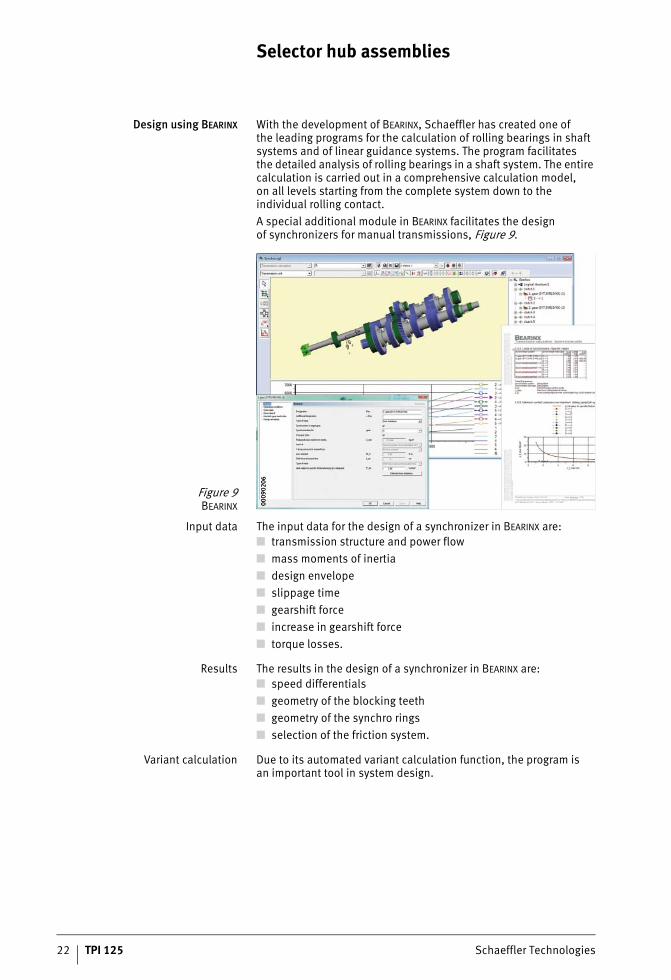
Design using BEARINX With the development of BEARINX, Schaeffler has created one ofthe leading programs for the calculation of rolling bearings in shaft systems and of linear guidance systems. The program facilitatesthe detailed analysis of rolling bearings in a shaft system. The entire calculation is carried out in a comprehensive calculation model,on all levels starting from the complete system down to the individual rolling contact.A special additional module in BEARINX facilitates the designof synchronizers for manual transmissions, Figure 9.
Input data The input data for the design of a synchronizer in BEARINX are:■ transmission structure and power flow■ mass moments of inertia■ design envelope■ slippage time■ gearshift force■ increase in gearshift force■ torque losses.
Results The results in the design of a synchronizer in BEARINX are:■ speed differentials■ geometry of the blocking teeth■ geometry of the synchro rings■ selection of the friction system.
Variant calculation Due to its automated variant calculation function, the program isan important tool in system design.
Figure 9BEARINX 00
0902
0600
0902
06
Schaeffler Technologies TPI 125 23
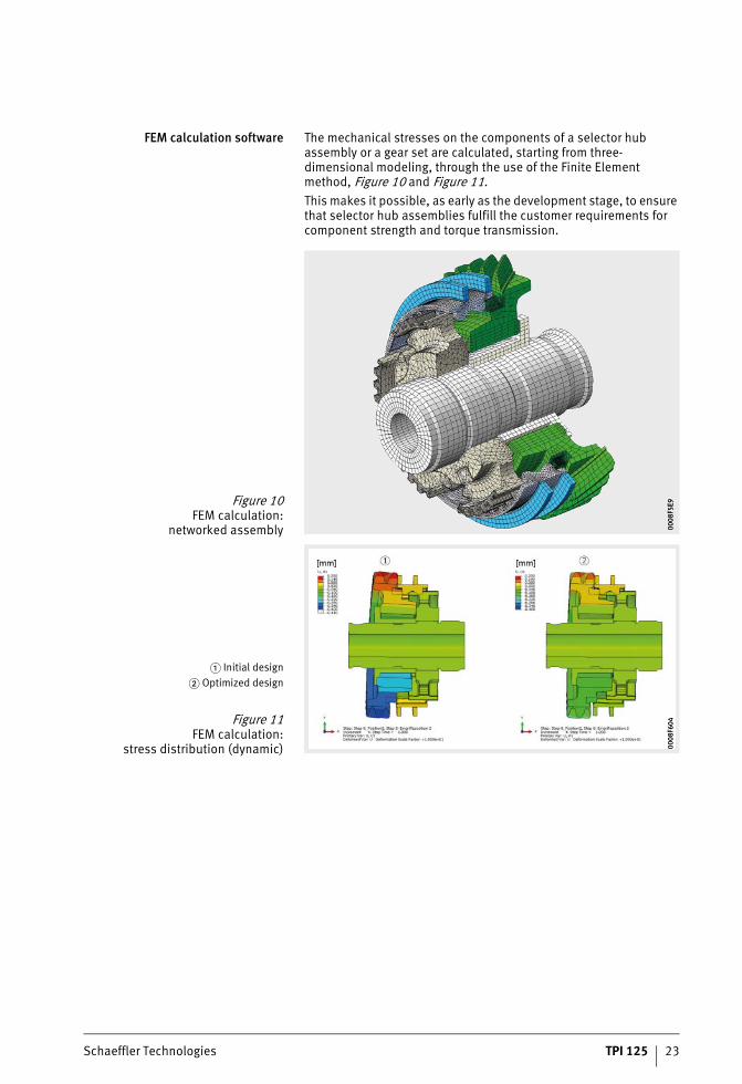
FEM calculation software The mechanical stresses on the components of a selector hub assembly or a gear set are calculated, starting from three-dimensional modeling, through the use of the Finite Element method, Figure 10 and Figure 11.This makes it possible, as early as the development stage, to ensure that selector hub assemblies fulfill the customer requirements for component strength and torque transmission.
Figure 10FEM calculation:
networked assembly 0008
F5E9
0008
F5E9
� Initial design� Optimized design
Figure 11FEM calculation:
stress distribution (dynamic) 0008
F604
0008
F604

24 TPI 125 Schaeffler Technologies
Selector hub assemblies
Interactive gearshift simulator The interactive gearshift simulator makes it possible to predictand display the effects of geometrical changes to components ofthe synchronizer or the gearshift unit on the gearshift sensation.The simulation is based on a design program that is integrated inthe development software and calculates the gearshift forces.The gearshift forces calculated in this way are then transmitted tothe simulator gearstick in such a way that they can be experienced as a gearshift feel, Figure 12.Through the simulation of design changes and the comparison of variants, the number of iteration loops in the development process can be reduced.
Figure 12Interactive gearshift simulator 00
08E9
2A00
08E9
2A

Schaeffler Technologies TPI 125 25
Test methodsfor product development
Versatile test devices are available for the development of selector hub assemblies. The test methods described below and the associated test rigs are important examples taken from the extensive testing portfolio.In addition to values such as fatigue strength and operating lifethat are clearly defined and quantifiable, other characteristics such as gearshift comfort can also be investigated.
Operating life and functional testingin the transmission
In long term tests, function over the entire operating life of the trans-mission is studied. The test rigs can also be used, however, for pure functional measurements. For example, gearshift forces can be determined by the use of a gearshift robot.The advantage of testing of gearshift systems in the complete transmission compared to testing in a subsystem is that the test conditions can be matched particularly closely to the application.A large number of parameters such as torque, gearshift forces,oil flow quantity or oil temperature can be controled in accordance with the test specification or measured as part of the test result.Various test rigs allow matching to different vehicle types. In the sim-plest case, the drive and load are simulated by two electric motors. With the use of three electric motors, it is possible to simulate different speeds of the drive wheels and thus travel around a corner or bend, Figure 13.
Operating life and functional testingof the synchronization subsystem
In addition to testing in the complete transmission, the operating life and function of synchronization systems are also investigated in so-called synchro test rigs. The object of the test is a unit comprising two gear wheels and the components arranged between them (gear cone body, synchro rings, selector hub, selector sleeve and detent struts). In contrast to testing in the transmission, this specifically tests the gearshift function but not the transmission of torque.
Figure 13Operating life and functional testing
in the transmission 0008
E094
0008
E094

26 TPI 125 Schaeffler Technologies
Selector hub assemblies
Measurement of gearshift comfortin the transmission
Despite the use of versatile simulation tools in the development process, extensive experimental studies are carried out to assess gearshift comfort. The focus of these studies is on determiningthe gearshift and selection forces occurring when changing gear. Comparisons can thus be made between simulated and measured forces, Figure 14.
Measurement of gearshift comfortin the vehicle
One the test rig tests have been completed successfully, the gear-shift components are instaled in vehicles and assessed in relationto gearshift comfort.The capture of gearshift forces and speeds by measurement tech-nology makes it possible to take account of the individual influence of operators and their different gearshift behavior in the assessment of gearshift comfort. In addition, automated data capture facilitates long term monitoring under actual operating conditions in the vehicle, Figure 15.
Figure 14Measurement of gearshift comfort
in the transmission 0008
E098
0008
E098
Figure 15Measurement of gearshift comfort
in the vehicle 0008
E09C
0008
E09C

Schaeffler Technologies TPI 125 27
Fatigue strength testing The fatigue strength of a synchronization system is tested onthe pulser by means of defined force applications. The test structure facilitates testing under torsion load, Figure 16.
Test methods for confirmationof manufacturing processes
Manufacturing processes are confirmed using both static as well as dynamic test methods.
Static washer separation testing The objective of this test is to demonstrate the strength of the weld connections between the thrust washers and the sleeve body.The thrust washers are subjected to a defined force in an axial direction, Figure 17, �.
Static tear strength testing The objective of this test is to demonstrate the strength of the weld seam in the clinch or butt joint area. The weld seam is subjectedto a defined force in accordance with the tensile test principle, Figure 17, �.
� Selector sleeve� Gear wheel
Figure 16Fatigue strength testing
under torsion load 0008
E2BE
0008
E2BE
� Static washer separation testing� Static tear strength testing
Figure 17Static tests on selector sleeve 00
08E2
BA00
08E2
BA

28 TPI 125 Schaeffler Technologies
Selector hub assemblies
Dynamic axial loadingof selector sleeve
The objective of this test is to demonstrate the fatigue strengthof the weld connections between the thrust washers and the sleeve body.
Dynamic radial loadingof selector sleeve
The objective of this test is to demonstrate the fatigue strengthof the weld seam in the clinch or butt joint area, Figure 18.
Dynamic gearshift fork testing The objective of this test is to investigate the wear behavior ofthe friction combination between the gearshift fork and the selector sleeve. The selector sleeve is rotated at a defined speed.At the same time, the gearshift fork meshing in the gearshift fork slot on the selector sleeve is subjected to a dynamic axial load.In order to investigate the strength under misuse, the axial force can be increased to 5 kN.
Source:Fraunhofer LBF
Figure 18Dynamic radial loading
of selector sleeve 0008
E2B6
0008
E2B6

Schaeffler Technologies TPI 125 29
Selector sleevesAvailable designs
Symmetrical Asymmetrical Tooth set
0008
8E92
0008
8E92
0008
8E8A
0008
8E8A
0008
8E8E
0008
8E8E
1) Dimension can be modified.2) If two values are given for the roof angle: alternative designs are available.
Dimension table · Dimensions in mm
Desig-nation
Maximum torque
Dimensions Tooth set Positionof gearshiftfork relativeto base body1)
A1) E F G1) Roof angle1)2)
B C D Modulus
Nm °
S1 1 000 102 91,5 19,47 9,85 114 – 84,05 85,32 88,6 1,58 Symmetrical
S2 1 400 105,6 97 23,13 9,15 85 80 88,15 90 91,8 1,5 Asymmetrical
S3 1 400 91,3 86,1 19,77 10,35 90 120 79,05 81 82,36 1,5 Symmetrical
S4 1 200 101 92,1 19,77 7,1 84 – 84,05 85,32 88,6 1,58 Asymmetrical
S5 1 000 96,1 86,1 19,77 9 90 120 79,05 81 82,36 1,5 Symmetrical
S6 1 400 105,6 97 23,13 9,15 85 80 88,15 90 91,8 1,5 Asymmetrical
S7 1 600 104,1 95,55 25,8 8,1 85 92 87,3 86,4 91,65 1,6 Symmetrical
S8 1 600 104,1 95,55 25,8 8,1 85 117 87,3 86,4 91,65 1,6 Symmetrical
S9 1 000 114,9 106,9 21,3 10,1 115 – 97,5 96 102,3 2 Symmetrical
S10 2 000 116,5 107,6 23,8 12,05 115 90 99,4 102 102,95 1,7 Symmetrical
S11 1 200 104,9 96,9 21,5 10,05 115 – 87,6 90 92,4 2 Symmetrical
S12 1 200 96,5 88,4 19,36 8,75 117 – 80,2 81,6 84,6 1,7 Symmetrical
S13 1 800 127 114 23,2 8,28 110 – 104,6 108,3 109,2 1,9 Symmetrical
S14 1 200 104 91 21,4 8,28 110 – 81,8 85,5 86,4 1,9 Symmetrical
S15 1 800 123 114 22,8 8,28 110 – 104,6 108,3 109,2 1,9 Symmetrical
S16 1 000 89,3 80,25 20,65 7,15 90 116 71,75 73,5 76,1 1,75 Asymmetrical
S17 1 000 89,3 80,25 20,65 8,05 90 116 71,75 73,5 76,1 1,75 Asymmetrical
S18 1 000 89,3 80,25 22,5 8,05 90 116 71,75 73,5 76,1 1,75 Asymmetrical
S19 1 000 92,3 80,25 20,2 8,05 116 – 71,75 73,5 76,1 1,75 Asymmetrical

Checklist for selector hub assembly
Basic information
Device designation:
Transmission type:
Number of gears:
Engine input torque:
Feature/ / / /
Gear pair
Conversion ratio
Gearshift force N
Gearshift time ms
Maximum speed min–1
Differential speed min–1
Background
❑ New development ❑ Optimization
❑ Cost reduction ❑ Other:
Planned implementation
Synchronizer type:
❑ Single cone synchronizer in gear:
❑ Double cone synchronizer in gear:
❑ Triple cone synchronizer in gear:
❑ Other system:
Presynchronization:
❑ ARRES
❑ Other system:
Environmental conditions
Transmission oil:
❑ Contamination conditions (standard):
❑ Operating temperature range:
❑ Special features:
Adjacent construction
Drawings:
❑ Transmission ❑ Selector sleeve ❑ Presynchronization
❑ Selector hub ❑ Synchro ring(s) ❑ Gear cone body
❑ Gear wheels ❑ Gearshift fork

Checklist for selector hub assembly
Information on design envelope (if no appropriate drawing available)
Feature/ / / /
Gear pair
Design envelope of selector hub assembly (largest diameter and width)
Material of gearshift fork shoe:
Connection of gear cone body to gear
Information on components
Selector sleeve = SYTM/selector hub = SYTK
Material
Feature / / / /
Gear pair SYTM SYTK SYTM SYTK SYTM SYTK SYTM SYTK
Material
Density g/cm3
Strength N/mm2
Hardness
Surface treatment
Clutching teeth
Feature / / / /
Gear pair SYTM SYTK SYTM SYTK SYTM SYTK SYTM SYTK
Number of teeth
Modulus mm
Pitch circle diameter mm
Mesh angle °
Profile displacement mm
Tip pitch circle diameter mm
Root diameter mm
Back angle °
Roof angle °
Roof pitch °
Angleof presynchronization slot °
Ball diameterof detent strut mm

Checklist for selector hub assembly
Dimensions of gearshift fork slot in selector sleeve
Feature/ / / /
Gear pair
Diameter mm
Width mm
Position of gearshift fork slot
Other information on selector sleeve
Feature/ / / /
Gear pair
Planned wear travel mm
Gearshift travel mm
Gearshift travel limiter(examples: collar, stop)
Special characteristics(examples: reduced flank,different tooth lengths)
Shaft/hub connection
Feature/ / / /
Gear pair
Tooth data for shaft/hub
Fit (press fit, clearance)
Mounting concept
Test conditions
Planned tests, specifications:
Mounting and packaging
Method of mounting at customer:
❑ Manual ❑ Automatic
❑ Special packaging required:


Schaeffler Technologies AG & Co. KG
Industriestraße 1–391074 HerzogenaurachGermanyInternet www.schaeffler.de/enE-mail [email protected]
In Germany:Phone 0180 5003872Fax 0180 5003873
From other countries:Phone +49 9132 82-0Fax +49 9132 82-4950
Every care has been taken to ensure the
correctness of the information contained
in this publication but no liability can be
accepted for any errors or omissions.
We reserve the right to make technical
changes.
© Schaeffler Technologies AG & Co. KG
Issued: 2015, October
This publication or parts thereof may not
be reproduced without our permission.
TPI 125 GB-DMAT
NR
0232
0330
7-00
00 /
TPI
125
/ G
B-D
/ 2
0151
0.5
/ Pr
inte
d in
Ger
man
y by
bre
sler