self-clinching nuts
TRANSCRIPT
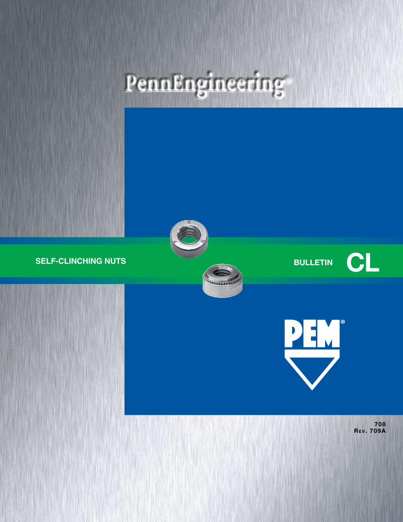
BULLETIN CLSELF-CLINCHING NUTS
708RE v. 709A
CL-2 PennEngineering • www.pemnet.com
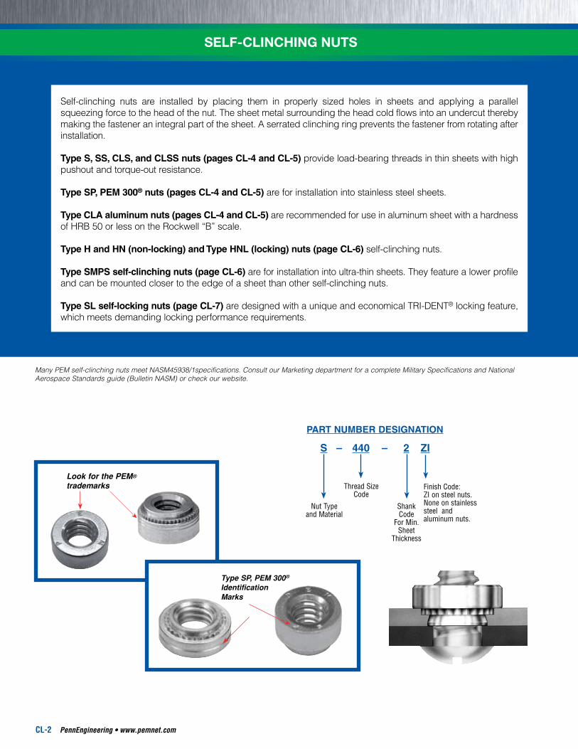
Many PEM self-clinching nuts meet NASM45938/1specifications. Consult our Marketing department for a complete Military Specifications and National Aerospace Standards guide (Bulletin NASM) or check our website.
Self-clinching nuts are installed by placing them in properly sized holes in sheets and applying a parallel squeezing force to the head of the nut. The sheet metal surrounding the head cold flows into an undercut thereby making the fastener an integral part of the sheet. A serrated clinching ring prevents the fastener from rotating after installation.
Type S, SS, CLS, and CLSS nuts (pages CL-4 and CL-5) provide load-bearing threads in thin sheets with high pushout and torque-out resistance.
Type SP, PEM 300® nuts (pages CL-4 and CL-5) are for installation into stainless steel sheets.
Type CLA aluminum nuts (pages CL-4 and CL-5) are recommended for use in aluminum sheet with a hardness of HRB 50 or less on the Rockwell “B” scale.
Type H and HN (non-locking) and Type HNL (locking) nuts (page CL-6) self-clinching nuts.
Type SMPS self-clinching nuts (page CL-6) are for installation into ultra-thin sheets. They feature a lower profile and can be mounted closer to the edge of a sheet than other self-clinching nuts.
Type SL self-locking nuts (page CL-7) are designed with a unique and economical TRI-DENT® locking feature, which meets demanding locking performance requirements.
SELF-CLINCHING NUTS
S – 440 – 2 ZI
Finish Code:ZI on steel nuts.None on stainless steel and aluminum nuts.
PART NUMBER DESIGNATION
Nut Typeand Material
Thread SizeCode
ShankCode
For Min. Sheet
Thickness
Look for the PEM® trademarks
Type SP, PEM 300® Identification Marks
PennEngineering • www.pemnet.com CL-3
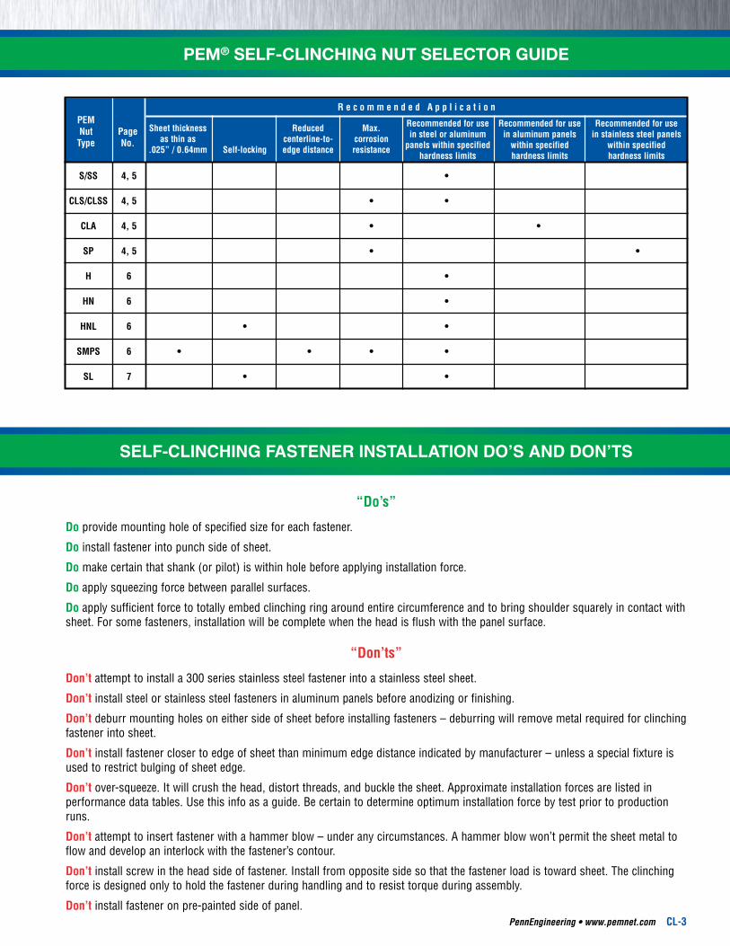
PEM® SELF-CLINCHING NUT SELECTOR GUIDE
Sheet thickness Reduced Max. Recommended for use Recommended for use Recommended for use as thin as centerline-to- corrosion in steel or aluminum in aluminum panels in stainless steel panels .025” / 0.64mm Self-locking edge distance resistance panels within specified within specified within specified hardness limits hardness limits hardness limits
R e c o m m e n d e d A p p l i c a t i o n PEM Nut Page Type No.
S/SS 4,5 •
CLS/CLSS 4,5 • •
CLA 4,5 • •
SP 4,5 • •
H 6 •
HN 6 •
HNL 6 • •
SMPS 6 • • • •
SL 7 • •
“Do’s”
Do provide mounting hole of specified size for each fastener.
Do install fastener into punch side of sheet.
Do make certain that shank (or pilot) is within hole before applying installation force.
Do apply squeezing force between parallel surfaces.
Do apply sufficient force to totally embed clinching ring around entire circumference and to bring shoulder squarely in contact with sheet. For some fasteners, installation will be complete when the head is flush with the panel surface.
“Don’ts”
Don’t attempt to install a 300 series stainless steel fastener into a stainless steel sheet.
Don’t install steel or stainless steel fasteners in aluminum panels before anodizing or finishing.
Don’t deburr mounting holes on either side of sheet before installing fasteners – deburring will remove metal required for clinching fastener into sheet.
Don’t install fastener closer to edge of sheet than minimum edge distance indicated by manufacturer – unless a special fixture is used to restrict bulging of sheet edge.
Don’t over-squeeze. It will crush the head, distort threads, and buckle the sheet. Approximate installation forces are listed in performance data tables. Use this info as a guide. Be certain to determine optimum installation force by test prior to production runs.
Don’t attempt to insert fastener with a hammer blow – under any circumstances. A hammer blow won’t permit the sheet metal to flow and develop an interlock with the fastener’s contour.
Don’t install screw in the head side of fastener. Install from opposite side so that the fastener load is toward sheet. The clinching force is designed only to hold the fastener during handling and to resist torque during assembly.
Don’t install fastener on pre-painted side of panel.
SELF-CLINCHING FASTENER INSTALLATION DO’S AND DON’TS
CL-4 PennEngineering • www.pemnet.com
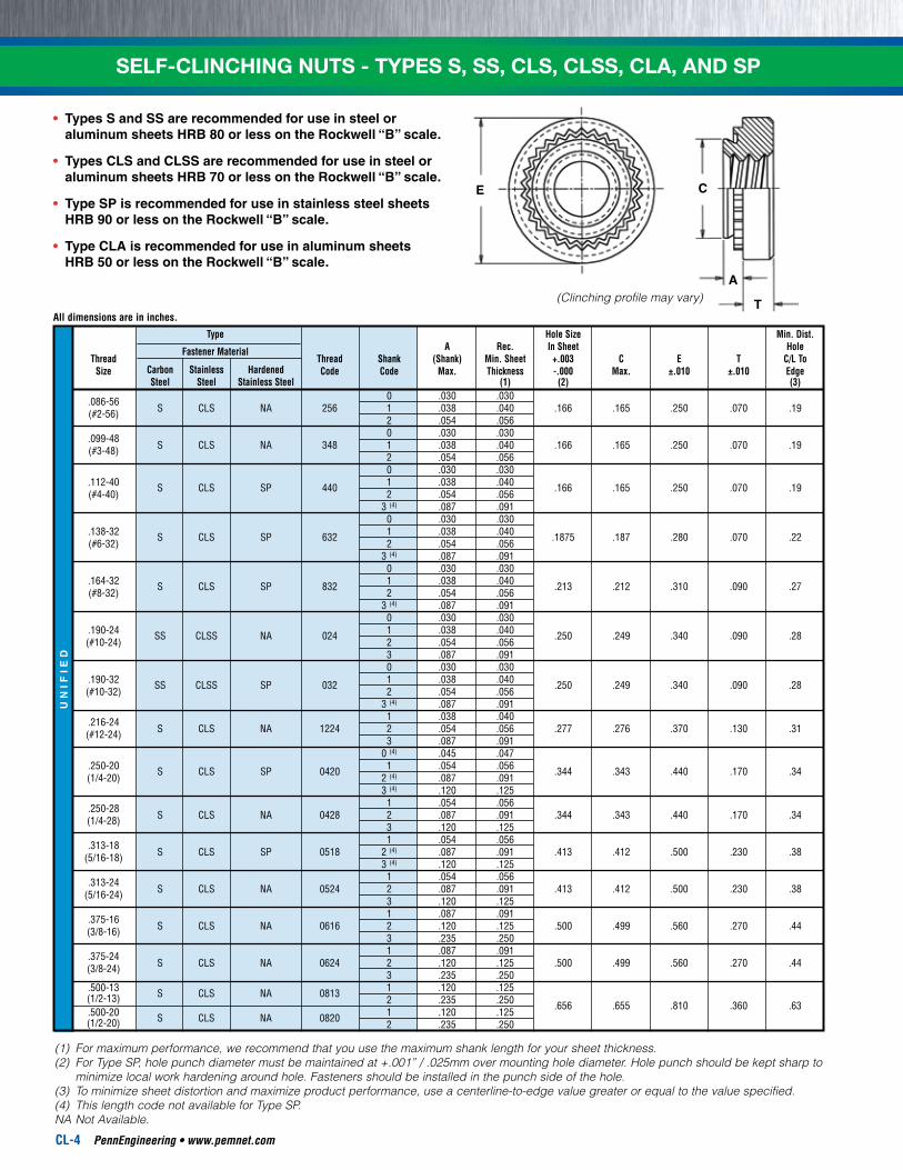
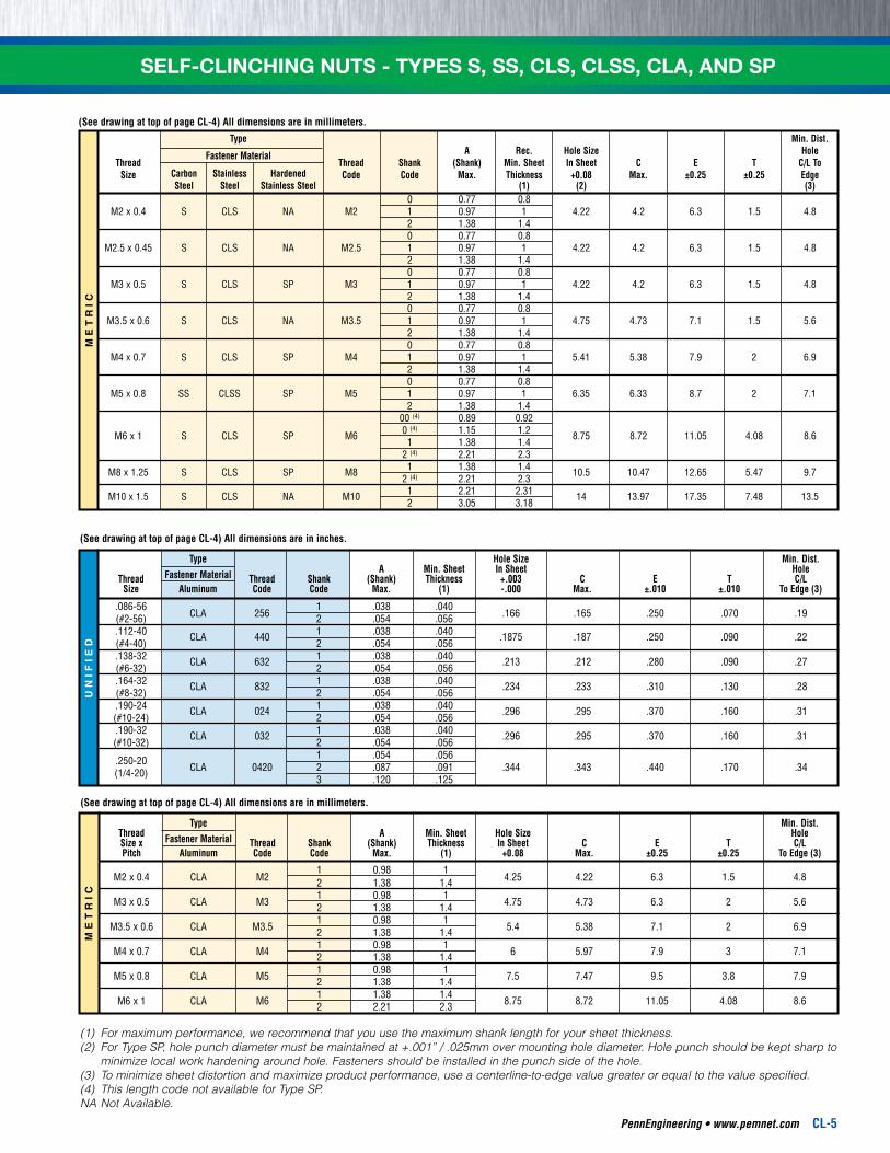
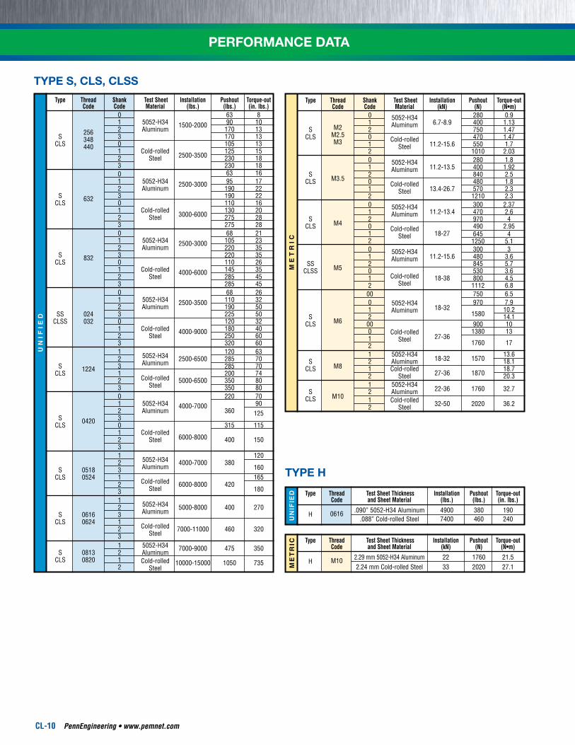
SELF-CLINCHING NUTS - TYPES S, SS, CLS, CLSS, CLA, AND SPU
NIF
IED
Type Hole Size Min. Dist. A Rec. In Sheet Hole Thread
Fastener Material Thread Shank (Shank) Min. Sheet +.003 C E T C/L To
Size Carbon Stainless Hardened Code Code Max. Thickness -.000 Max. ±.010 ±.010 Edge Steel Steel Stainless Steel (1) (2) (3) .086-56 0 .030 .030 (#2-56) S CLS NA 256 1 .038 .040 .166 .165 .250 .070 .19 2 .054 .056 .099-48 0 .030 .030 (#3-48) S CLS NA 348 1 .038 .040 .166 .165 .250 .070 .19 2 .054 .056 0 .030 .030 .112-40 S CLS SP 440 1 .038 .040 .166 .165 .250 .070 .19 (#4-40) 2 .054 .056 3 (4) .087 .091 0 .030 .030 .138-32 S CLS SP 632 1 .038 .040 .1875 .187 .280 .070 .22 (#6-32) 2 .054 .056 3 (4) .087 .091 0 .030 .030 .164-32 S CLS SP 832 1 .038 .040 .213 .212 .310 .090 .27 (#8-32) 2 .054 .056 3 (4) .087 .091 0 .030 .030 .190-24 SS CLSS NA 024 1 .038 .040 .250 .249 .340 .090 .28 (#10-24) 2 .054 .056 3 .087 .091 0 .030 .030 .190-32 SS CLSS SP 032 1 .038 .040 .250 .249 .340 .090 .28 (#10-32) 2 .054 .056 3 (4) .087 .091 .216-24 1 .038 .040 (#12-24) S CLS NA 1224 2 .054 .056 .277 .276 .370 .130 .31 3 .087 .091 0 (4) .045 .047 .250-20 S CLS SP 0420 1 .054 .056 .344 .343 .440 .170 .34 (1/4-20) 2 (4) .087 .091 3 (4) .120 .125 .250-28 1 .054 .056 (1/4-28) S CLS NA 0428 2 .087 .091 .344 .343 .440 .170 .34 3 .120 .125 .313-18 1 .054 .056 (5/16-18) S CLS SP 0518 2 (4) .087 .091 .413 .412 .500 .230 .38 3 (4) .120 .125 .313-24 1 .054 .056 (5/16-24) S CLS NA 0524 2 .087 .091 .413 .412 .500 .230 .38 3 .120 .125 .375-16 1 .087 .091 (3/8-16) S CLS NA 0616 2 .120 .125 .500 .499 .560 .270 .44 3 .235 .250 .375-24 1 .087 .091 (3/8-24) S CLS NA 0624 2 .120 .125 .500 .499 .560 .270 .44 3 .235 .250 .500-13 S CLS NA 0813 1 .120 .125 (1/2-13) 2 .235 .250 .656 .655 .810 .360 .63 .500-20 S CLS NA 0820 1 .120 .125 (1/2-20) 2 .235 .250
CE
A
T(Clinching profile may vary)
(1) For maximum performance, we recommend that you use the maximum shank length for your sheet thickness.(2) For Type SP, hole punch diameter must be maintained at +.001” / .025mm over mounting hole diameter. Hole punch should be kept sharp to
minimize local work hardening around hole. Fasteners should be installed in the punch side of the hole.(3) To minimize sheet distortion and maximize product performance, use a centerline-to-edge value greater or equal to the value specified.(4) This length code not available for Type SP.NA Not Available.
All dimensions are in inches.
• Types S and SS are recommended for use in steel or aluminum sheets HRB 80 or less on the Rockwell “B” scale.
• Types CLS and CLSS are recommended for use in steel or aluminum sheets HRB 70 or less on the Rockwell “B” scale.
• Type SP is recommended for use in stainless steel sheets HRB 90 or less on the Rockwell “B” scale.
• Type CLA is recommended for use in aluminum sheets HRB 50 or less on the Rockwell “B” scale.
PennEngineering • www.pemnet.com CL-5
ME
TR
ICU
NIF
IED
(See drawing at top of page CL-4) All dimensions are in millimeters.
Type Min. Dist. Thread Fastener Material A Min. Sheet Hole Size Hole Size x Thread Shank (Shank) Thickness In Sheet C E T C/L Pitch Aluminum Code Code Max. (1) +0.08 Max. ±0.25 ±0.25 To Edge (3)
1 0.98 1 M2 x 0.4 CLA M2 2 1.38 1.4 4.25 4.22 6.3 1.5 4.8
1 0.98 1 M3 x 0.5 CLA M3 2 1.38 1.4 4.75 4.73 6.3 2 5.6
1 0.98 1 M3.5 x 0.6 CLA M3.5 2 1.38 1.4 5.4 5.38 7.1 2 6.9
1 0.98 1 M4 x 0.7 CLA M4 2 1.38 1.4 6 5.97 7.9 3 7.1
1 0.98 1 M5 x 0.8 CLA M5 2 1.38 1.4 7.5 7.47 9.5 3.8 7.9
1 1.38 1.4 M6 x 1 CLA M6 2 2.21 2.3 8.75 8.72 11.05 4.08 8.6
(See drawing at top of page CL-4) All dimensions are in inches.
Type Hole Size Min. Dist. Fastener Material A Min. Sheet In Sheet Hole Thread Thread Shank (Shank) Thickness +.003 C E T C/L Size Aluminum Code Code Max. (1) -.000 Max. ±.010 ±.010 To Edge (3)
.086-56 CLA 256
1 .038 .040 .166 .165 .250 .070 .19 (#2-56) 2 .054 .056
.112-40 CLA 440 1 .038 .040 .1875 .187 .250 .090 .22 (#4-40) 2 .054 .056 .138-32 CLA 632 1 .038 .040 .213 .212 .280 .090 .27 (#6-32) 2 .054 .056 .164-32 CLA 832 1 .038 .040 .234 .233 .310 .130 .28 (#8-32) 2 .054 .056 .190-24 CLA 024 1 .038 .040 .296 .295 .370 .160 .31 (#10-24) 2 .054 .056 .190-32 CLA 032 1 .038 .040 .296 .295 .370 .160 .31 (#10-32) 2 .054 .056 .250-20 1 .054 .056 (1/4-20) CLA 0420 2 .087 .091 .344 .343 .440 .170 .34 3 .120 .125
SELF-CLINCHING NUTS - TYPES S, SS, CLS, CLSS, CLA, AND SPM
ET
RIC
Type Min. Dist. A Rec. Hole Size Hole Thread
Fastener Material Thread Shank (Shank) Min. Sheet In Sheet C E T C/L To
Size Carbon Stainless Hardened Code Code Max. Thickness +0.08 Max. ±0.25 ±0.25 Edge Steel Steel Stainless Steel (1) (2) (3) 0 0.77 0.8 M2 x 0.4 S CLS NA M2 1 0.97 1 4.22 4.2 6.3 1.5 4.8 2 1.38 1.4 0 0.77 0.8 M2.5 x 0.45 S CLS NA M2.5 1 0.97 1 4.22 4.2 6.3 1.5 4.8 2 1.38 1.4 0 0.77 0.8 M3 x 0.5 S CLS SP M3 1 0.97 1 4.22 4.2 6.3 1.5 4.8 2 1.38 1.4 0 0.77 0.8 M3.5 x 0.6 S CLS NA M3.5 1 0.97 1 4.75 4.73 7.1 1.5 5.6 2 1.38 1.4 0 0.77 0.8 M4 x 0.7 S CLS SP M4 1 0.97 1 5.41 5.38 7.9 2 6.9 2 1.38 1.4 0 0.77 0.8 M5 x 0.8 SS CLSS SP M5 1 0.97 1 6.35 6.33 8.7 2 7.1 2 1.38 1.4 00 (4) 0.89 0.92 M6 x 1 S CLS SP M6 0 (4) 1.15 1.2 8.75 8.72 11.05 4.08 8.6 1 1.38 1.4 2 (4) 2.21 2.3 M8 x 1.25 S CLS SP M8 1 1.38 1.4 10.5 10.47 12.65 5.47 9.7 2 (4) 2.21 2.3 M10 x 1.5 S CLS NA M10 1 2.21 2.31 14 13.97 17.35 7.48 13.5 2 3.05 3.18
(See drawing at top of page CL-4) All dimensions are in millimeters.
(1) For maximum performance, we recommend that you use the maximum shank length for your sheet thickness.(2) For Type SP, hole punch diameter must be maintained at +.001” / .025mm over mounting hole diameter. Hole punch should be kept sharp to
minimize local work hardening around hole. Fasteners should be installed in the punch side of the hole.(3) To minimize sheet distortion and maximize product performance, use a centerline-to-edge value greater or equal to the value specified.(4) This length code not available for Type SP.NA Not Available.
CL-6 PennEngineering • www.pemnet.com
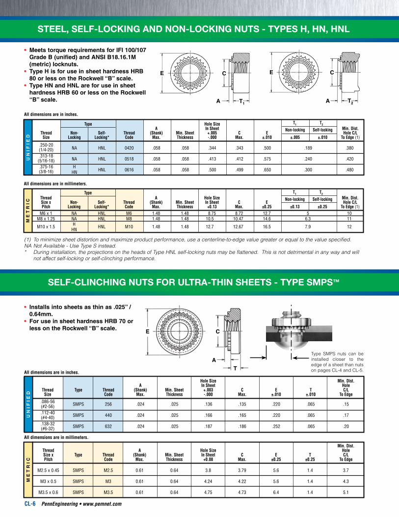
STEEL, SELF-LOCKING AND NON-LOCKING NUTS - TYPES H, HN, HNLM
ET
RIC
UN
IFIE
D
E
T1
C
A T2
C
A
E
All dimensions are in millimeters.
Type T1 T2 Thread A Hole Size Min. Dist. Size x Non- Self- Thread (Shank) Min. Sheet In Sheet C E
Non-locking Self-locking Hole C/L
Pitch Locking Locking* Code Max. Thickness +0.13 Max. ±0.25 ±0.13 ±0.25 To Edge (1) M6 x 1 NA HNL M6 1.48 1.48 8.75 8.72 12.7 5 10 M8 x 1.25 NA HNL M8 1.48 1.48 10.5 10.47 14.6 6.3 11 M10 x 1.5 H HNL M10 1.48 1.48 12.7 12.67 16.5 7.9 12 HN
All dimensions are in inches.
Type Hole Size T1 T2 A In Sheet Min. Dist. Thread Non- Self- Thread (Shank) Min. Sheet +.005 C E
Non-locking Self-locking Hole C/L
Size Locking Locking* Code Max. Thickness -.000 Max. ±.010 ±.005 ±.010 To Edge (1)
.250-20 NA HNL 0420 .058 .058 .344 .343 .500 .189 .380 (1/4-20)
.313-18 NA HNL 0518 .058 .058 .413 .412 .575 .240 .420 (5/16-18)
.375-16 H HNL 0616 .058 .058 .500 .499 .650 .300 .480 (3/8-16) HN
(1) To minimize sheet distortion and maximize product performance, use a centerline-to-edge value greater or equal to the value specified.NA Not Available - Use Type S instead.* During installation, the projections on the heads of Type HNL self-locking nuts may be flattened. This is not detrimental in any way and will
not affect self-locking or self-clinching performance.
ME
TR
ICU
NIF
IED
All dimensions are in millimeters.
Min. Dist. Thread A Hole Size Hole Size x Type Thread (Shank) Min. Sheet In Sheet C E T C/L Pitch Code Max. Thickness +0.08 Max. ±0.25 ±0.25 To Edge M2.5 x 0.45 SMPS M2.5 0.61 0.64 3.8 3.79 5.6 1.4 3.7
M3 x 0.5 SMPS M3 0.61 0.64 4.24 4.22 5.6 1.4 4.3
M3.5 x 0.6 SMPS M3.5 0.61 0.64 4.75 4.73 6.4 1.4 5.1
All dimensions are in inches.
Hole Size Min. Dist. A In Sheet Hole Thread Type Thread (Shank) Min. Sheet +.003 C E T C/L Size Code Max. Thickness -.000 Max. ±.010 ±.010 To Edge
.086-56 SMPS 256 .024 .025 .136 .135 .220 .065 .15 (#2-56) .112-40 SMPS 440 .024 .025 .166 .165 .220 .065 .17 (#4-40) .138-32 SMPS 632 .024 .025 .187 .186 .252 .065 .20 (#6-32)
C
AT
E
Type SMPS nuts can be installed closer to the edge of a sheet than nuts on pages CL-4 and CL-5.
SELF-CLINCHING NUTS FOR ULTRA-THIN SHEETS - TYPE SMPS™
•Meets torque requirements for IFI 100/107 Grade B (unified) and ANSI B18.16.1M (metric) locknuts.
•Type H is for use in sheet hardness HRB 80 or less on the Rockwell “B” scale.
•Type HN and HNL are for use in sheet hardness HRB 60 or less on the Rockwell “B” scale.
•Installs into sheets as thin as .025” / 0.64mm.
•For use in sheet hardness HRB 70 or less on the Rockwell “B” scale.
PennEngineering • www.pemnet.com CL-7
ME
TR
ICU
NIF
IED
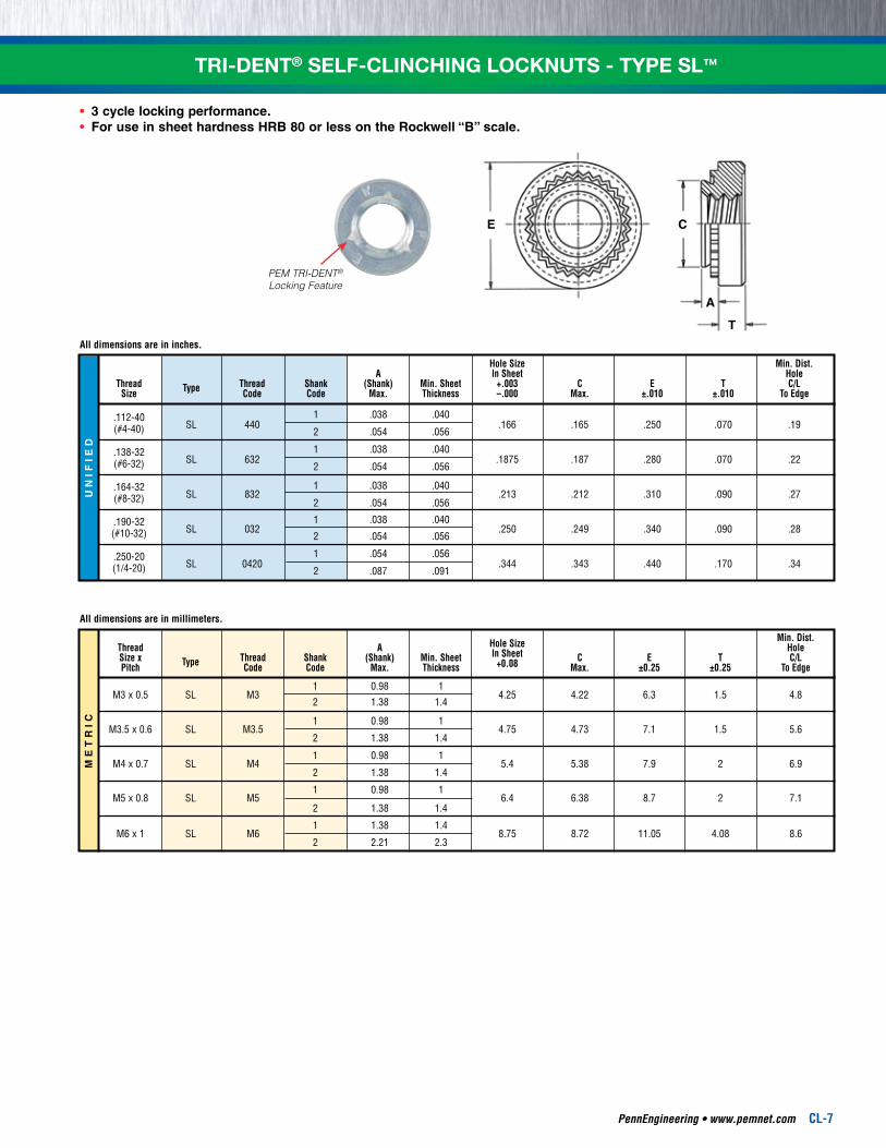
PEM TRI-DENT®
Locking Feature
E C
A
T
All dimensions are in inches.
Hole Size Min. Dist. A In Sheet Hole Thread Type Thread Shank (Shank) Min. Sheet +.003 C E T C/L Size Code Code Max. Thickness –.000 Max. ±.010 ±.010 To Edge
.112-40 SL 440
1 .038 .040 .166 .165 .250 .070 .19
(#4-40) 2 .054 .056
.138-32 SL 632
1 .038 .040 .1875 .187 .280 .070 .22 (#6-32) 2 .054 .056
.164-32 SL 832
1 .038 .040 .213 .212 .310 .090 .27 (#8-32) 2 .054 .056
.190-32
SL 032 1 .038 .040
.250 .249 .340 .090 .28 (#10-32) 2 .054 .056
.250-20 SL 0420
1 .054 .056 .344 .343 .440 .170 .34 (1/4-20) 2 .087 .091
All dimensions are in millimeters.
Hole Size Min. Dist. Thread A In Sheet Hole Size x Type Thread Shank (Shank) Min. Sheet +0.08 C E T C/L Pitch Code Code Max. Thickness Max. ±0.25 ±0.25 To Edge
1 0.98 1
M3 x 0.5 SL M3
2 1.38 1.4 4.25 4.22 6.3 1.5 4.8
1 0.98 1
M3.5 x 0.6 SL M3.5
2 1.38 1.4 4.75 4.73 7.1 1.5 5.6
1 0.98 1
M4 x 0.7 SL M4
2 1.38 1.4 5.4 5.38 7.9 2 6.9
1 0.98 1
M5 x 0.8 SL M5
2 1.38 1.4 6.4 6.38 8.7 2 7.1
1 1.38 1.4
M6 x 1 SL M6
2 2.21 2.3 8.75 8.72 11.05 4.08 8.6
TRI-DENT® SELF-CLINCHING LOCKNUTS - TYPE SL™
•3 cycle locking performance.•For use in sheet hardness HRB 80 or less on the Rockwell “B” scale.
CL-8 PennEngineering • www.pemnet.com
INSTALLATION
ME
TR
ICU
NIF
IED
ME
TR
ICU
NIF
IED
RECOMMENDEDRAISED RING
INSTALLATIONANVIL
A1
B
P1 R2 Sharp.No burrs
120˚
RECOMMENDEDCOUNTERBORED
INSTALLATIONPUNCH
RR1
P
A
Punch Dimensions (in.) Thread A P R R1 Punch Code ±.002 ±.001 Max. +.005 Part No. 440 .255 .066 .010 .005 8002691 632 .286 .066 .010 .005 8002692 832 .317 .089 .010 .005 8002693 032 .348 .089 .010 .005 8002694 0420 — — — — (3)
Punch Dimensions (mm) Thread A P R R1 Punch Code ±0.05 ±0.03 Max. +0.13 Part No. M3 6.48 1.42 0.25 0.13 8002695 M3.5 7.26 1.42 0.25 0.13 8002696 M4 8.05 1.93 0.25 0.13 8002697 M5 8.84 1.93 0.25 0.13 8002698 M6 — — — — (3)
(1) To meet the published performance data, we recommend using the installation punch and anvil shown. Deviations from recommended installation tooling may result in sheet distortion and reduced performance.
(2) We recommend replacing installation anvil when the height of the “P1” dimension is reduced to .005” / 0.13mm due to wear. Reductions in performance may occur as the height of the protrusion wears.
(3) Special installation tooling for #0420 and M6 thread sizes is not required.NOTE: Variations in hole preparation, installation tooling, installation force, and sheet material type, thickness, and hardness will affect both performance and tooling life.
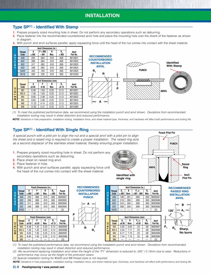
A special punch with a pilot pin to align the nut and a special anvil with a pilot pin to align the sheet and a raised ring is required to create a proper installation. The raised ring acts as a second displacer of the stainless sheet material, thereby ensuring proper installation.
Identified with single ring
Anvil Dimensions (in.) Thread A1 B P1 (2) R2 Anvil Code ±.002 Nom. +.001 -.000 Max. Part No. 440 .199 .261 .009 .003 8002687 632 .218 .280 .009 .003 8002688 832 .243 .305 .009 .003 8002689 032 .288 .350 .009 .003 8002690 0420 — — — — (3)
Anvil Dimensions (mm) Thread A1 B P1 (2) R2 Anvil Code ±0.05 Nom. +0.03 Max. Part No. M3 5.05 6.63 .23 .08 8002687 M3.5 5.54 7.11 .23 .08 8002688 M4 6.17 7.75 .23 .08 8002689 M5 7.34 7.75 .23 .08 8002690 M6 — — — — (3)
RaisedRing
Punch Pilot Pin
AnvilPilot Pin
PUNCH
ANVIL
1. Prepare properly sized mounting hole in sheet. Do not perform any secondary operations such as deburring.2. Place fastener into the recommended counterbored anvil hole and place the mounting hole over the shank of the fastener as shown
in diagram.3. With punch and anvil surfaces parallel, apply squeezing force until the head of the nut comes into contact with the sheet material.
IdentifiedWith Stamp
RECOMMENDEDCOUNTERBORED
INSTALLATIONANVIL
RR1
P
A
Type SP(1) - Identified With Single Ring
Type SP(1) - Identified With Stamp
1. Prepare properly sized mounting hole in sheet. Do not perform any secondary operations such as deburring.
2. Place sheet on raised ring anvil.3. Place fastener in hole.4. With punch and anvil surfaces parallel, apply squeezing force until
the head of the nut comes into contact with the sheet material.
(1) To meet the published performance data, we recommend using the installation punch and anvil shown. Deviations from recommended installation tooling may result in sheet distortion and reduced performance.
NOTE: Variations in hole preparation, installation tooling, installation force, and sheet material type, thickness, and hardness will affect both performance and tooling life.
ME
TR
ICU
NIF
IED
Anvil Dimensions (in.) Thread A P +.000 R R1 Anvil Code ±.002 –.001 Max. +.005 Part No. 440 .255 .064 .010 .005 8012821 632 .286 .064 .010 .005 8012822 832 .317 .082 .010 .005 8012823 032 .348 .082 .010 .005 8012824 0420 .443 .163 .010 .005 8012825 0518 .505 .230 .010 .005 8015359
Anvil Dimensions (mm) Thread A P R R1 Anvil Code ±0.05 –0.03 Max. +0.13 Part No. M3 6.48 1.63 0.25 0.13 8012821 M3.5 7.26 1.63 0.25 0.13 8012822 M4 8.05 2.08 0.25 0.13 8012823 M5 8.84 2.08 0.25 0.13 8012824 M6 11.25 4.14 0.25 0.13 8012825 M8 12.83 5.41 0.25 0.13 8015360
PUNCH
ANVIL
PennEngineering • www.pemnet.com CL-9
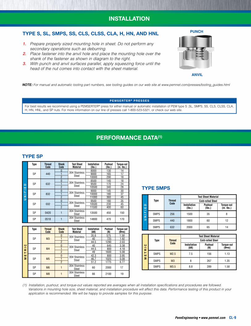
INSTALLATION
TYPE S, SL, SMPS, SS, CLS, CLSS, CLA, H, HN, AND HNL
1. Prepare properly sized mounting hole in sheet. Do not perform any secondary operations such as deburring.
2. Place fastener into the anvil hole and place the mounting hole over the shank of the fastener as shown in diagram to the right.
3. With punch and anvil surfaces parallel, apply squeezing force until the head of the nut comes into contact with the sheet material.
ANVIL
PUNCH
For best results we recommend using a PEMSERTER® press for either manual or automatic installation of PEM type S ,SL, SMPS, SS, CLS, CLSS, CLA, H, HN, HNL, and SP nuts. For more information on our line of presses call 1-800-523-5321, or check our web site.
PEMSERTER ® PRESSES
NOTE: For manual and automatic tooling part numbers, see tooling guides on our web site at www.pemnet.com/presses/tooling_guides.html
ME
TR
ICU
NIF
IED
ME
TR
ICU
NIF
IED
Test Sheet Material Type Thread Cold-rolled Steel Code Installation Pushout Torque-out (kN) (N) (N•m)
SMPS M2.5 7.5 156 1.13
SMPS M3 8 267 1.35
SMPS M3.5 8.8 289 1.58
Test Sheet Material Type Thread Cold-rolled Steel Code Installation Pushout Torque-out (lbs.) (lbs.) (in. lbs.)
SMPS 256 1500 35 8
SMPS 440 1800 60 12
SMPS 632 2000 65 14 Type Thread Shank Test Sheet Installation Pushout Torque-out Code Code Material (kN) (N) (N•m) 0 35.6 575 1.58 SP M3 1
304 Stainless 40 725 1.92
2 Steel
44.5 1290 2.03 0 40 645 3.38 SP M4 1
304 Stainless 44.5 800 4.18
2 Steel
49 1600 5.08 0 42.3 800 3.95 SP M5 1
304 Stainless 46.7 1025 5.08
2 Steel
51.2 1775 6.77
SP M6 1 304 Stainless
60 2000 17 Steel
SP M8 1 304 Stainless
66 2100 19 Steel
Type Thread Shank Test Sheet Installation Pushout Torque-out Code Code Material (lbs.) (lbs.) (in. lbs.) 0
304 Stainless 8000 130 14
SP 440 1 Steel
9000 165 17 2 10000 290 18 0
304 Stainless 8500 140 18
SP 632 1 Steel
9500 170 24 2 10500 340 28 0
304 Stainless 9000 145 30
SP 832 1 Steel
10000 180 37 2 11000 360 45 0
304 Stainless 9500 180 35
SP 032 1 Steel
10500 230 45 2 11500 400 60
SP 0420 1 304 Stainless
13500 450 150 Steel
SP 0518 1 304 Stainless
14800 470 170 Steel
TYPE SP
TYPE SMPS
(1) Installation, pushout, and torque-out values reported are averages when all installation specifications and procedures are followed. Variations in mounting hole size, sheet material, and installation procedure will affect this data. Performance testing of this product in your application is recommended. We will be happy to provide samples for this purpose.
PERFORMANCE DATA(1)
CL-10 PennEngineering • www.pemnet.com
ME
TR
ICU
NIF
IED
ME
TR
IC
UN
IFIE
D
Type Thread Test Sheet Thickness Installation Pushout Torque-out Code and Sheet Material (lbs.) (lbs.) (in. lbs.)
H 0616 .090” 5052-H34 Aluminum 4900 380 190
.088” Cold-rolled Steel 7400 460 240
Type Thread Test Sheet Thickness Installation Pushout Torque-out Code andSheetMaterial (kN) (N) (N•m)
H M10 2.29 mm 5052-H34 Aluminum 22 1760 21.5
2.24 mm Cold-rolled Steel 33 2020 27.1
Type Thread Shank Test Sheet Installation Pushout Torque-out Code Code Material (lbs.) (lbs.) (in. lbs.) 0 63 8 1 5052-H34 90 10 2 Aluminum
1500-2000 170 13
S 256
3 170 13 CLS
348 0 105 13
440
1 Cold-rolled 2500-3500
125 15 2 Steel 230 18 3 230 18 0 63 16 1 5052-H34 95 17 2 Aluminum
2500-3000 190 22
S 3 190 22 CLS
632 0 110 16
1 Cold-rolled 3000-6000
130 20 2 Steel 275 28 3 275 28 0 68 21 1 5052-H34 105 23 2 Aluminum
2500-3000 220 35
S 3 220 35 CLS
832 0 110 26
1 Cold-rolled 145 35 2 Steel
4000-6000 285 45
3 285 45 0 68 26 1 5052-H34 110 32 2 Aluminum
2500-3500 190 50
SS 024 3 225 50 CLSS 032 0 120 32 1 Cold-rolled 180 40 2 Steel
4000-9000 250 60
3 320 60 1
5052-H34 120 63
2 Aluminum
2500-6500 285 70 S 3 285 70 CLS
1224 1
Cold-rolled 200 74
2 Steel
5000-6500 350 80 3 350 80 0 220 70 1 5052-H34 90 2 Aluminum
4000-7000 360
S 3 125
CLS 0420
0 315 115 1 Cold-rolled
6000-8000
2 Steel 400 150 3 1
5052-H34 120
2 Aluminum
4000-7000 380 160 S 0518 3
CLS 0524 1 Cold-rolled
165 2
Steel 6000-8000 420
180 3 1
5052-H34
2 Aluminum
5000-8000 400 270 S 0616 3 CLS 0624 1
Cold-rolled 2 Steel
7000-11000 460 320 3 1 5052-H34 S 0813 2 Aluminum
7000-9000 475 350
CLS 0820 1 Cold-rolled 2 Steel
10000-15000 1050 735
Type Thread Shank Test Sheet Installation Pushout Torque-out Code Code Material (kN) (N) (N•m) 0 280 0.9 1
5052-H34 6.7-8.9 400 1.13
S M2 2 Aluminum
750 1.47 CLS M2.5 0 470 1.47 M3 1
Cold-rolled 11.2-15.6 550 1.7
2 Steel
1010 2.03 0 280 1.8 1
5052-H34 11.2-13.5 400 1.92
S M3.5
2 Aluminum
840 2.5 CLS 0 480 1.8 1
Cold-rolled 13.4-26.7 570 2.3
2 Steel
1210 2.3 0 300 2.37 1
5052-H34 11.2-13.4 470 2.6
S M4
2 Aluminum
970 4 CLS 0 490 2.95 1
Cold-rolled 18-27 645 4
2 Steel
1250 5.1 0 300 3 1
5052-H34 11.2-15.6 480 3.6
SS M5
2 Aluminum
845 5.7 CLSS 0 530 3.6 1 Cold-rolled 18-38 800 4.5 2 Steel 1112 6.8 00 750 6.5 0 970 7.9 1
5052-H34 18-32
1580 10.2
S M6
2 Aluminum
14.1 CLS 00 900 10 0 1380 13 1
Cold-rolled 27-36
1760 17 2 Steel
1 5052-H34 18-32 1570
13.6 S
M8 2 Aluminum 18.1
CLS 1 Cold-rolled 27-36 1870
18.7 2 Steel 20.3 1 5052-H34
22-36 1760 32.7 S M10
2 Aluminum CLS 1 Cold-rolled
32-50 2020 36.2 2 Steel
PERFORMANCE DATA
TYPE S, CLS, CLSS
TYPE H
PennEngineering • www.pemnet.com CL-11
PERFORMANCE DATAU
NIF
IED
Thread Locking Specifications (1) Test Sheet Material Type Thread Shank Max. Torque Min. Torque 5052-H34 Aluminum Cold-rolled Steel Code Code (1st thru 3rd) (1st thru 3rd) Installation Pushout Torque-out Installation Pushout Torque-out (in. lbs.) (in. lbs.) (lbs.) (lbs.) (in. lbs.) (lbs.) (lbs.) (in. lbs.)
SL 440 1 5.75 0.4 1500 - 2000 90 10 2500 - 3500 125 15 2 170 13 230 18 SL 632 1 10.5 0.8 2500 - 3000 95 17 3000 - 6000 130 20 2 190 22 275 28 SL 832 1 18 1.2 2500 - 3000 105 23 4000 - 6000 145 35 2 220 35 285 45 SL 032 1 21 1.65 2500 - 3000 110 32 4000 - 9000 180 40 2 190 50 250 60 SL 0420 1 35 3.75 4000 - 7000 360 90 6000 - 9000 400 150 2 360 125 400 150
(1) 3 cycle locking performance. PEM spec PRS-C90 Max. on / Min. off torque for 1st thru 3rd cycles.
TYPE SL
ME
TR
IC
Thread Locking Specifications (1) Test Sheet Material Type Thread Shank Max. Torque Min. Torque 5052-H34 Aluminum Cold-rolled Steel Code Code (1st thru 3rd) (1st thru 3rd) Installation Pushout Torque-out Installation Pushout Torque-out (N•m) (N•m) (kN) (N) (N•m) (kN) (N) (N•m)
SL M3 1 0.67 0.04 6.7 - 8.9 400 1.13 11.2 - 15.6 550 1.7 2 750 1.47 1010 2.03 SL M3.5 1 1.2 0.08 11.2 - 13.5 400 1.92 13.4 - 26.7 570 2.3 2 840 2.5 1210 2.3 SL M4 1 2.1 0.13 11.2 - 13.4 470 2.6 18 - 27 645 4 2 970 4 1250 5.1 SL M5 1 2.4 0.18 11.2 - 15.6 480 3.6 18 - 38 800 4.5 2 845 5.7 1112 6.8 SL M6 1 4 0.30 18 - 32 1580 10.2 27 - 38 1760 17 2 1580 14.1 1760 17
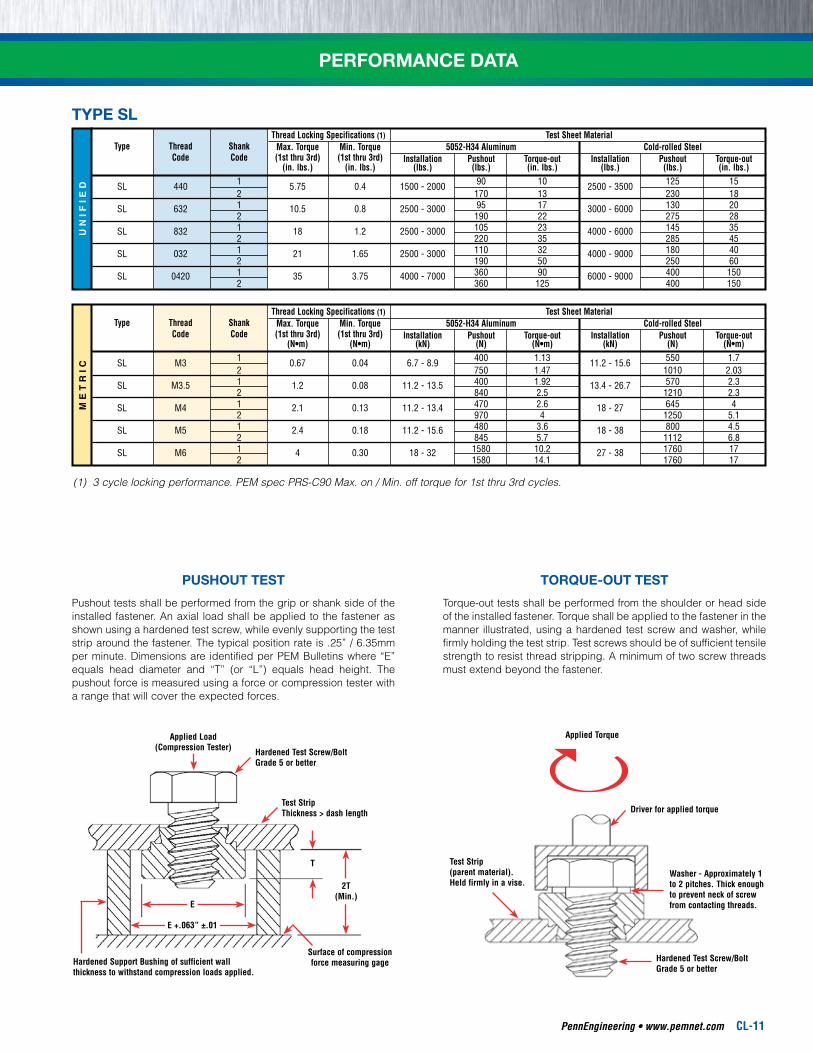
PUSHOUT TEST TORQUE-OUT TEST
Pushout tests shall be performed from the grip or shank side of the installed fastener. An axial load shall be applied to the fastener as shown using a hardened test screw, while evenly supporting the test strip around the fastener. The typical position rate is .25” / 6.35mm per minute. Dimensions are identified per PEM Bulletins where “E” equals head diameter and “T” (or “L”) equals head height. The pushout force is measured using a force or compression tester with a range that will cover the expected forces.
Torque-out tests shall be performed from the shoulder or head side of the installed fastener. Torque shall be applied to the fastener in the manner illustrated, using a hardened test screw and washer, while firmly holding the test strip. Test screws should be of sufficient tensile strength to resist thread stripping. A minimum of two screw threads must extend beyond the fastener.
Applied Load(Compression Tester) Hardened Test Screw/Bolt
Grade 5 or better
Test StripThickness > dash length
Surface of compression force measuring gage
T
Hardened Support Bushing of sufficient wall thickness to withstand compression loads applied.
E
E +.063” ±.01
2T(Min.)
Applied Torque
Driver for applied torque
Washer - Approximately 1 to 2 pitches. Thick enough to prevent neck of screw from contacting threads.
Hardened Test Screw/Bolt Grade 5 or better
Test Strip(parent material).Held firmly in a vise.
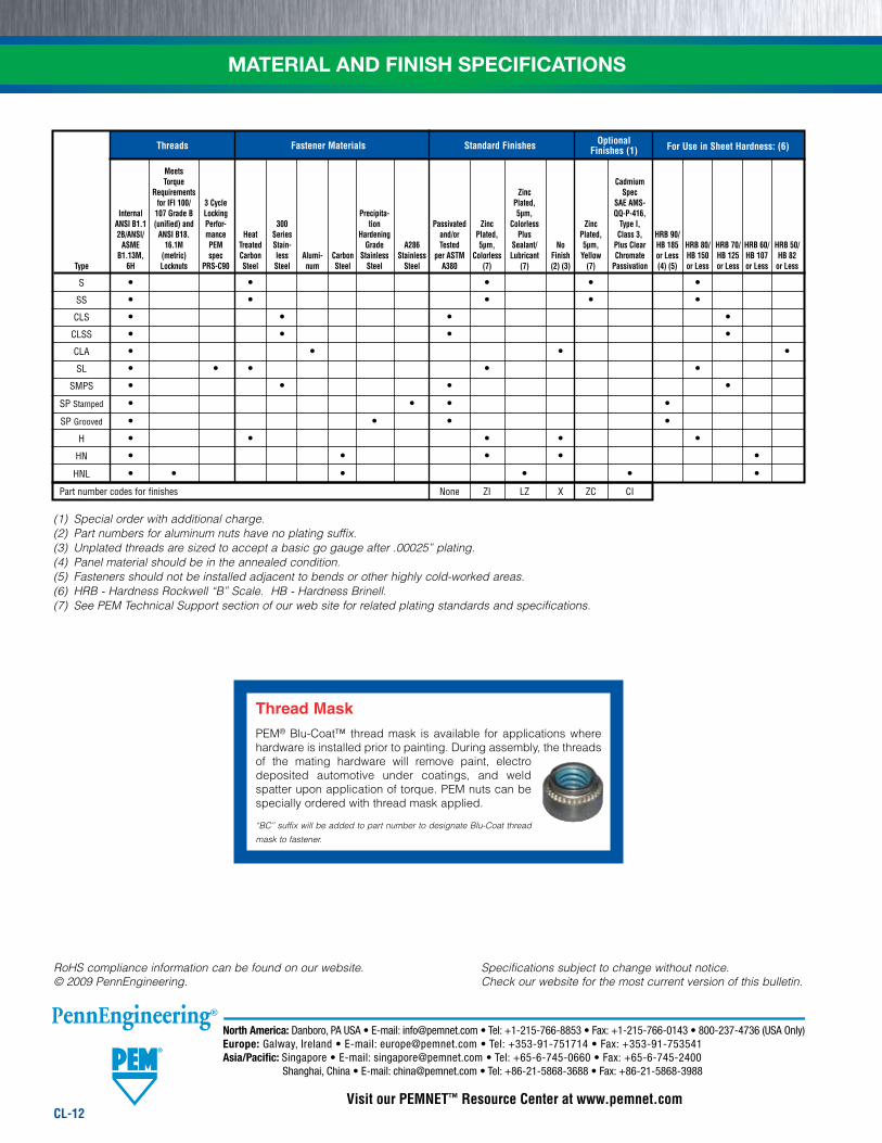
Threads Fastener Materials Standard Finishes Optional Finishes (1) For Use in Sheet Hardness: (6)
Meets Torque Cadmium Requirements Zinc Spec for IFI 100/ 3 Cycle Plated, SAE AMS- Internal 107 Grade B Locking Precipita- 5µm, QQ-P-416, ANSI B1.1 (unified) and Perfor- 300 tion Passivated Zinc Colorless Zinc Type I, 2B/ANSI/ ANSI B18. mance Heat Series Hardening and/or Plated, Plus Plated, Class 3, HRB 90/ ASME 16.1M PEM Treated Stain- Grade A286 Tested 5µm, Sealant/ No 5µm, Plus Clear HB 185 HRB 80/ HRB 70/ HRB 60/ HRB 50/ B1.13M, (metric) spec Carbon less Alumi- Carbon Stainless Stainless per ASTM Colorless Lubricant Finish Yellow Chromate or Less HB 150 HB 125 HB 107 HB 82 Type 6H Locknuts PRS-C90 Steel Steel num Steel Steel Steel A380 (7) (7) (2) (3) (7) Passivation (4) (5) or Less or Less or Less or Less
S • • • • •
SS • • • • •
CLS • • • •
CLSS • • • •
CLA • • • •
SL • • • • •
SMPS • • • •
SP Stamped • • • •
SP Grooved • • • •
H • • • • •
HN • • • • •
HNL • • • • • •
Part number codes for finishes None ZI LZ X ZC CI
CL-12
(1) Special order with additional charge.(2) Part numbers for aluminum nuts have no plating suffix.(3) Unplated threads are sized to accept a basic go gauge after .00025” plating.(4) Panel material should be in the annealed condition.(5) Fasteners should not be installed adjacent to bends or other highly cold-worked areas.(6) HRB - Hardness Rockwell “B” Scale. HB - Hardness Brinell.(7) See PEM Technical Support section of our web site for related plating standards and specifications.
Specifications subject to change without notice. Check our website for the most current version of this bulletin.
RoHS compliance information can be found on our website.© 2009 PennEngineering.
MATERIAL AND FINISH SPECIFICATIONS
Thread MaskPEM® Blu-Coat™ thread mask is available for applications where hardware is installed prior to painting. During assembly, the threads of the mating hardware will remove paint, electro deposited automotive under coatings, and weld spatter upon application of torque. PEM nuts can be specially ordered with thread mask applied.
“BC” suffix will be added to part number to designate Blu-Coat thread
mask to fastener.