self-clinching studs and pins - techford.com · fh-2 pem® self-clinching studs are installed by...
TRANSCRIPT
712Re v 812
SeLF-CLINCHING STUDS AND PINS BULLeTIN FH
FH-2
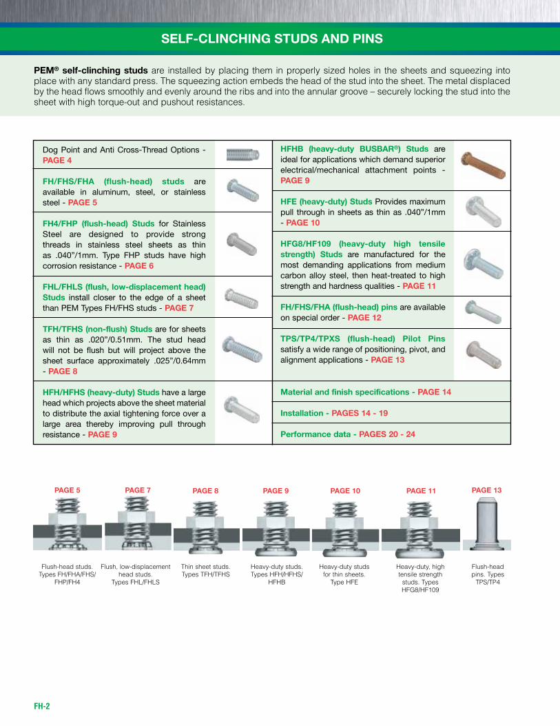
PEM® self-clinching studs are installed by placing them in properly sized holes in the sheets and squeezing into place with any standard press. The squeezing action embeds the head of the stud into the sheet. The metal displaced by the head flows smoothly and evenly around the ribs and into the annular groove – securely locking the stud into the sheet with high torque-out and pushout resistances.
SELF-CLINCHING STUDS AND PINS
Flush, low-displacementhead studs.
Types FHL/FHLS
Heavy-duty studs.Types HFH/HFHS/
HFHB
Thin sheet studs.Types TFH/TFHS
Flush-headpins. Types
TPS/TP4
Flush-head studs.Types FH/FHA/FHS/
FHP/FH4
Heavy-duty studsfor thin sheets.
Type HFE
Heavy-duty, high tensile strength
studs. Types HFG8/HF109
PAGE 5 PAGE 7 PAGE 8 PAGE 9 PAGE 10 PAGE 11 PAGE 13
Dog Point and Anti Cross-Thread Options - PAGE 4
FH/FHS/FHA (flush-head) studs are available in aluminum, steel, or stainless steel - PAGE 5
FH4/FHP (flush-head) Studs for Stainless Steel are designed to provide strong threads in stainless steel sheets as thin as .040”/1mm. Type FHP studs have high corrosion resistance - PAGE 6
FHL/FHLS (flush, low-displacement head) Studs install closer to the edge of a sheet than PEM Types FH/FHS studs - PAGE 7
TFH/TFHS (non-flush) Studs are for sheets as thin as .020”/0.51mm. The stud head will not be flush but will project above the sheet surface approximately .025”/0.64mm - PAGE 8
HFH/HFHS (heavy-duty) Studs have a large head which projects above the sheet material to distribute the axial tightening force over a large area thereby improving pull through resistance - PAGE 9
HFHB (heavy-duty BUSBAR®) Studs are ideal for applications which demand superior electrical/mechanical attachment points - PAGE 9
HFE (heavy-duty) Studs Provides maximum pull through in sheets as thin as .040”/1mm - PAGE 10
HFG8/HF109 (heavy-duty high tensile strength) Studs are manufactured for the most demanding applications from medium carbon alloy steel, then heat-treated to high strength and hardness qualities - PAGE 11
FH/FHS/FHA (flush-head) pins are available on special order - PAGE 12
TPS/TP4/TPXS (flush-head) Pilot Pins satisfy a wide range of positioning, pivot, and alignment applications - PAGE 13
Material and finish specifications - PAGE 14
Installation - PAGES 14 - 19
Performance data - PAGES 20 - 24
FH-3
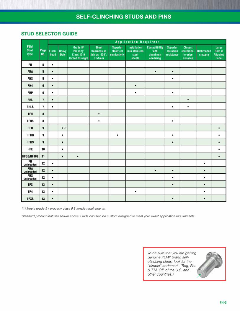
Grade 8/ Sheet Superior Installation Compatibility Superior Closest Large Flush- Heavy Property thickness as electrical into stainless with corrosion centerline- Unthreaded Hole in head Duty Class 10.9 thin as .020”/ conductivity steel aluminum resistance to-edge stud/pin Attached Thread Strength 0.51mm sheets anodizing distance Panel
A p p l i c a t i o n R e q u i r e s : PEM Stud Page Type No.
(1) Meets grade 5 / property class 9.8 tensile requirements.
Standard product features shown above. Studs can also be custom designed to meet your exact application requirements.
FH 5 •
FHA 5 • • •
FHS 5 • •
FH4 6 • •
FHP 6 • • •
FHL 7 • •
FHLS 7 • • •
TFH 8 •
TFHS 8 • •
HFH 9 • (1) •
HFHB 9 • • • •
HFHS 9 • • •
HFE 10 • •
HFG8/HF109 11 • • •
FH
12 • •
FHA
12 • • • •
FHS
12 • • •
TPS 13 • • •
TP4 13 • • •
TPXS 13 • • •
SELF-CLINCHING STUDS AND PINS
To be sure that you are getting genuine PEM® brand self-clinching studs, look for the “dimple” trademark. (Reg. Pat. & T.M. Off. of the U.S. and other countries.)
Unthreaded
Unthreaded
Unthreaded
STUD SELECTOR GUIDE
FH-4
SELF-CLINCHING STUDS AND PINS
ME
TR
IC
UN
IFIE
D
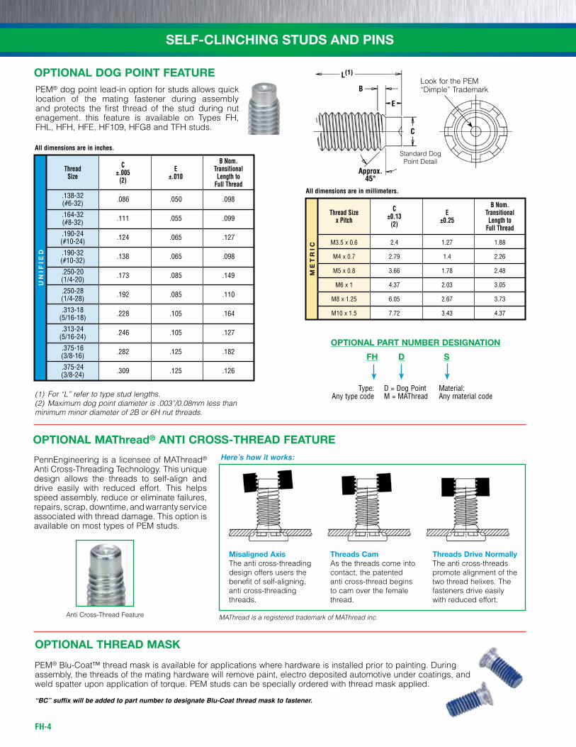
C B Nom. Thread ±.005 E Transitional Size (2) ±.010 Length to Full Thread
.138-32 .086 .050 .098 (#6-32)
.164-32 .111 .055 .099 (#8-32)
.190-24 .124 .065 .127 (#10-24)
.190-32 .138 .065 .098 (#10-32)
.250-20 .173 .085 .149 (1/4-20)
.250-28 .192 .085 .110 (1/4-28)
.313-18 .228 .105 .164 (5/16-18)
.313-24 .246 .105 .127 (5/16-24)
.375-16 .282 .125 .182 (3/8-16)
.375-24 .309 .125 .126 (3/8-24)
C B Nom. Thread Size ±0.13 E Transitional x Pitch (2) ±0.25 Length to Full Thread
M3.5 x 0.6 2.4 1.27 1.88
M4 x 0.7 2.79 1.4 2.26
M5 x 0.8 3.66 1.78 2.48
M6 x 1 4.37 2.03 3.05
M8 x 1.25 6.05 2.67 3.73
M10 x 1.5 7.72 3.43 4.37
PEM® dog point lead-in option for studs allows quick location of the mating fastener during assembly and protects the first thread of the stud during nut enagement. this feature is available on Types FH, FHL, HFH, HFE, HF109, HFG8 and TFH studs.
(1) For “L” refer to type stud lengths.(2) Maximum dog point diameter is .003”/0.08mm less than minimum minor diameter of 2B or 6H nut threads.
C
Approx.45°
E
B
L(1)Look for the PEM “Dimple” Trademark
Standard Dog Point Detail
PennEngineering is a licensee of MAThread® Anti Cross-Threading Technology. This unique design allows the threads to self-align and drive easily with reduced effort. This helps speed assembly, reduce or eliminate failures, repairs, scrap, downtime, and warranty service associated with thread damage. This option is available on most types of PEM studs.
Here’s how it works:
Misaligned AxisThe anti cross-threading design offers users the benefit of self-aligning, anti cross-threading threads.
Threads CamAs the threads come into contact, the patented anti cross-thread begins to cam over the female thread.
Threads Drive NormallyThe anti cross-threads promote alignment of the two thread helixes. The fasteners drive easily with reduced effort.
OPTIONAL MAThread® ANTI CROSS-THREAD FEATURE
Anti Cross-Thread Feature
All dimensions are in inches.
All dimensions are in millimeters.
FH D S
Type:Any type code
OPTIONAL PART NUMBER DESIGNATION
D = Dog PointM = MAThread
Material:Any material code
OPTIONAL DOG POINT FEATURE
OPTIONAL THREAD MASK
PEM® Blu-Coat™ thread mask is available for applications where hardware is installed prior to painting. Duringassembly, the threads of the mating hardware will remove paint, electro deposited automotive under coatings, andweld spatter upon application of torque. PEM studs can be specially ordered with thread mask applied.
“BC” suffix will be added to part number to designate Blu-Coat thread mask to fastener.
MAThread is a registered trademark of MAThread inc.
FH-5
ME
TR
ICU
NIF
IED
Type Length Code “L” ±.015 Min. Hole Max. Min. Fastener Material (Length Code in 16ths of an inch) Sheet Size in Hole Dist. Thread Thread Thick- Sheet in H S Hole Size Steel Stainless Alu- Code .250 .312 .375 .500 .625 .750 .875 1.00 1.25 1.50 ness +.003 Attach. ± .015 Max.
Steel minum (1) -.000 Parts (2) to Edge
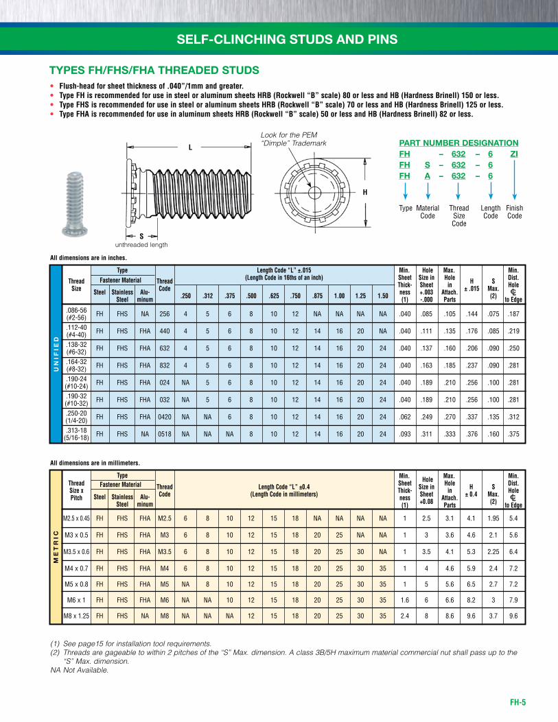
.086-56 fh fhs nA 256 4 5 6 8 10 12 nA nA nA nA .040 .085 .105 .144 .075 .187 (#2-56) .112-40 fh fhs fhA 440 4 5 6 8 10 12 14 16 20 nA .040 .111 .135 .176 .085 .219 (#4-40) .138-32 fh fhs fhA 632 4 5 6 8 10 12 14 16 20 24 .040 .137 .160 .206 .090 .250 (#6-32) .164-32 fh fhs fhA 832 4 5 6 8 10 12 14 16 20 24 .040 .163 .185 .237 .090 .281 (#8-32) .190-24 fh fhs fhA 024 nA 5 6 8 10 12 14 16 20 24 .040 .189 .210 .256 .100 .281 (#10-24) .190-32 fh fhs fhA 032 nA 5 6 8 10 12 14 16 20 24 .040 .189 .210 .256 .100 .281 (#10-32) .250-20 fh fhs fhA 0420 nA nA 6 8 10 12 14 16 20 24 .062 .249 .270 .337 .135 .312 (1/4-20) .313-18 fh fhs nA 0518 nA nA nA 8 10 12 14 16 20 24 .093 .311 .333 .376 .160 .375 (5/16-18)
Type
Length Code “L” ±0.4
Min. Hole Max. Min. Thread Fastener Material
(Length Code in millimeters)
Sheet Size in Hole Dist. Size x Thread Thick- Sheet in H S Hole Pitch Steel Stainless Alu- Code ness +0.08 Attach. ± 0.4 Max.
Steel minum (1) Parts (2) to Edge
M2.5 x 0.45 fh fhs fhA M2.5 6 8 10 12 15 18 nA nA nA nA 1 2.5 3.1 4.1 1.95 5.4
M3 x 0.5 fh fhs fhA M3 6 8 10 12 15 18 20 25 nA nA 1 3 3.6 4.6 2.1 5.6
M3.5 x 0.6 fh fhs fhA M3.5 6 8 10 12 15 18 20 25 30 nA 1 3.5 4.1 5.3 2.25 6.4
M4 x 0.7 fh fhs fhA M4 6 8 10 12 15 18 20 25 30 35 1 4 4.6 5.9 2.4 7.2
M5 x 0.8 fh fhs fhA M5 nA 8 10 12 15 18 20 25 30 35 1 5 5.6 6.5 2.7 7.2
M6 x 1 fh fhs fhA M6 nA nA 10 12 15 18 20 25 30 35 1.6 6 6.6 8.2 3 7.9
M8 x 1.25 fh fhs nA M8 nA nA nA 12 15 18 20 25 30 35 2.4 8 8.6 9.6 3.7 9.6
All dimensions are in inches.
All dimensions are in millimeters.
(1) See page15 for installation tool requirements.(2) Threads are gageable to within 2 pitches of the “S” Max. dimension. A class 3B/5H maximum material commercial nut shall pass up to the
“S” Max. dimension.NA Not Available.
• Flush-head for sheet thickness of .040”/1mm and greater.• Type FH is recommended for use in steel or aluminum sheets HRB (Rockwell “B” scale) 80 or less and HB (Hardness Brinell) 150 or less.• Type FHS is recommended for use in steel or aluminum sheets HRB (Rockwell “B” scale) 70 or less and HB (Hardness Brinell) 125 or less.• Type FHA is recommended for use in aluminum sheets HRB (Rockwell “B” scale) 50 or less and HB (Hardness Brinell) 82 or less.
L
H
Sunthreaded length
Look for the PEM “Dimple” Trademark
SELF-CLINCHING STUDS AND PINS
TYPES FH/FHS/FHA THREADED STUDS
Type
FH – 632 – 6 ZIFH S – 632 – 6FH A – 632 – 6
LengthCode
ThreadsizeCode
finish Code
MaterialCode
PART NUMBER DESIGNATION
FH-6
SELF-CLINCHING STUDS AND PINSM
ET
RIC
UN
IFIE
D
(1) See material and finish specifications chart on page 14 for details.(2) Threads are gageable to within 2 pitches of the “S” Max. dimension. A class 3B/5H maximum material commercial nut shall pass up to the
“S” Max. dimension.NA Not Available.
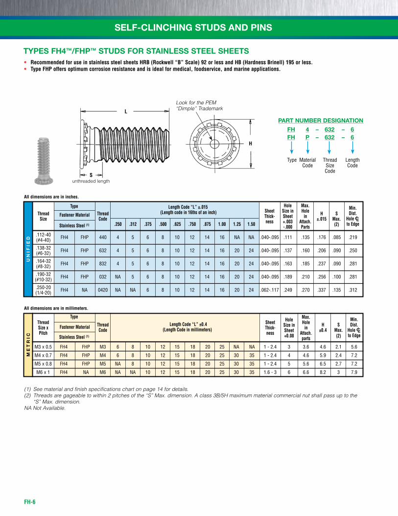
• Recommended for use in stainless steel sheets HRB (Rockwell “B” Scale) 92 or less and HB (Hardness Brinell) 195 or less.• Type FHP offers optimum corrosion resistance and is ideal for medical, foodservice, and marine applications.
Type Length Code “L” ±.015 Hole Max. Min. Thread Thread (Length code in 16ths of an inch) Sheet Size in Hole H S Dist. Size Fastener Material Code Thick- Sheet in ±.015 Max. HoleC/L .250 .312 .375 .500 .625 .750 .875 1.00 1.25 1.50 ness +.003 Attach. to Edge Stainless Steel (1) -.000 Parts (2)
.112-40 fh4 fhP 440 4 5 6 8 10 12 14 16 nA nA .040-.095 .111 .135 .176 .085 .219 (#4-40)
.138-32 fh4 fhP 632 4 5 6 8 10 12 14 16 20 24 .040-.095 .137 .160 .206 .090 .250 (#6-32)
.164-32 fh4 fhP 832 4 5 6 8 10 12 14 16 20 24 .040-.095 .163 .185 .237 .090 .281 (#8-32)
.190-32 fh4 fhP 032 nA 5 6 8 10 12 14 16 20 24 .040-.095 .189 .210 .256 .100 .281 (#10-32)
.250-20 fh4 nA 0420 nA nA 6 8 10 12 14 16 20 24 .062-.117 .249 .270 .337 .135 .312 (1/4-20)
Type Length Code “L” ±0.4
Hole Max. Min. Thread Thread
(Length Code in millimeters) Sheet Size in Hole H S Dist.
Size x Fastener Material Code Thick- Sheet in ±0.4 Max. HoleC/L Pitch ness +0.08 Attach. to Edge Stainless Steel (1) parts (2)
M3 x 0.5 fh4 fhP M3 6 8 10 12 15 18 20 25 nA nA 1 - 2.4 3 3.6 4.6 2.1 5.6
M4 x 0.7 fh4 fhP M4 6 8 10 12 15 18 20 25 30 35 1 - 2.4 4 4.6 5.9 2.4 7.2
M5 x 0.8 fh4 fhP M5 nA 8 10 12 15 18 20 25 30 35 1 - 2.4 5 5.6 6.5 2.7 7.2
M6 x 1 fh4 nA M6 nA nA 10 12 15 18 20 25 30 35 1.6 - 3 6 6.6 8.2 3 7.9
All dimensions are in inches.
All dimensions are in millimeters.
TYPES FH4™/FHP™ STUDS FOR STAINLESS STEEL SHEETS
L
H
Sunthreaded length
Look for the PEM “Dimple” Trademark
Type
FH 4 – 632 – 6FH P – 632 – 6
LengthCode
ThreadsizeCode
MaterialCode
PART NUMBER DESIGNATION
FH-7
SELF-CLINCHING STUDS AND PINSM
ET
RIC
UN
IFIE
D
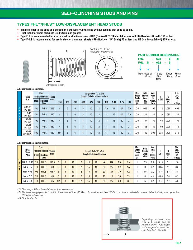
• Installs closer to the edge of a sheet than PEM Type FH/FHS studs without causing that edge to bulge.• Flush-head for sheet thickness .040”/1mm and greater.• Type FHL is recommended for use in steel or aluminum sheets HRB (Rockwell “B” Scale) 80 or less and HB (Hardness Brinell) 150 or less.• Type FHLS is recommended for use in steel or aluminum sheets HRB (Rockwell “B” Scale) 70 or less and HB (Hardness Brinell) 125 or less.
Type Min. Hole Max. Min. Fastener Material Sheet Size in Hole Dist. Thread Thread Thick- Sheet in H S Hole Size Steel Stainless Code .250 .312 .375 .500 .625 .750 .875 1.00 1.25 1.50 ness +.003 Attach. ±.015 Max.
Steel (1) -.000 Parts (2) to Edge
.086-56 fhL fhLs 256 4 5 6 8 10 12 nA nA nA nA .040 .085 .100 .112 .080 .098 (#2-56) .112-40 fhL fhLs 440 4 5 6 8 10 12 14 16 nA nA .040 .111 .125 .138 .085 .124 (#4-40) .138-32 fhL fhLs 632 4 5 6 8 10 12 14 16 20 24 .040 .137 .150 .164 .090 .150 (#6-32) .164-32 fhL fhLs 832 4 5 6 8 10 12 14 16 20 24 .040 .163 .180 .190 .090 .176 (#8-32) .190-32 fhL fhLs 032 nA 5 6 8 10 12 14 16 20 24 .040 .189 .205 .225 .100 .210 (#10-32)
Type Min. Hole Max. Min. Thread Fastener Material Sheet Size in Hole Dist. Size x Thread Thick- Sheet in H S Hole Pitch Steel Stainless Code ness +0.08 Attach. ±0.4 Max.
Steel (1) Parts (2) to Edge
M2.5 x 0.45 fhL fhLs M2.5 6 8 10 12 15 18 nA nA nA nA 1 2.5 2.9 3.15 2.1 2.8
M3 x 0.5 fhL fhLs M3 6 8 10 12 15 18 20 25 nA nA 1 3 3.4 3.65 2.1 3.3
M3.5 x 0.6 fhL fhLs M3.5 6 8 10 12 15 18 20 25 30 nA 1 3.5 3.9 4.15 2.3 3.8
M4 x 0.7 fhL fhLs M4 6 8 10 12 15 18 20 25 30 35 1 4 4.4 4.65 2.4 4.3
M5 x 0.8 fhL fhLs M5 nA 8 10 12 15 18 20 25 30 35 1 5 5.4 5.9 2.7 5.6
Depending on thread size, Type FHL studs can be installed almost 50% closer to the edge of a sheet than PEM Type FH/FHS studs.
All dimensions are in inches.
All dimensions are in millimeters.
Length Code “L” ±.015(Length Code in 16ths of an inch)
Length Code “L” ±0.4(Length Code in millimeters)
(1) See page 16 for installation tool requirements.(2) Threads are gageable to within 2 pitches of the “S” Max. dimension. A class 3B/5H maximum material commercial nut shall pass up to the
“S” Max. dimension.NA Not Available.
TYPES FHL™/FHLS™ LOW-DISPLACEMENT HEAD STUDS
H
S
L
unthreaded length
Look for the PEM “Dimple” Trademark
Type
FHL – 632 – 6 ZIFHL S – 632 – 6
LengthCode
ThreadsizeCode
finish Code
MaterialCode
PART NUMBER DESIGNATION
FH-8
SELF-CLINCHING STUDS AND PINSM
ET
RIC
UN
IFIE
D
Type Length Code “L” ±.015 Min. Hole Max. Min. Fastener Material (Length Code in 16ths of an inch) Sheet Size in Hole Dist. Thread Stainless Thread Thick- Sheet in H S T Hole Size Steel Steel
Code .250 .312 .375 .500 .625 .750 .875 1.00 1.25 1.50 ness +.003 Attach. ±.015 Max. Max.
(1) -.000 Parts (2) to Edge
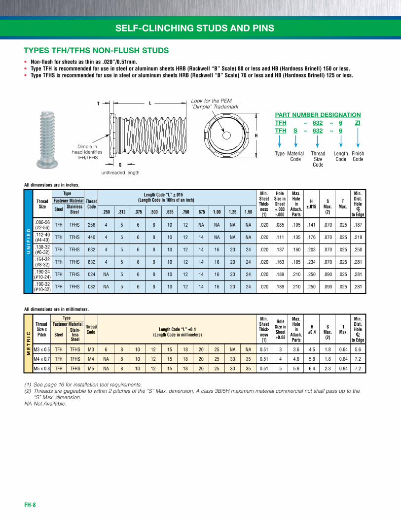
.086-56 Tfh Tfhs 256 4 5 6 8 10 12 nA nA nA nA .020 .085 .105 .141 .070 .025 .187 (#2-56) .112-40 Tfh Tfhs 440 4 5 6 8 10 12 14 nA nA nA .020 .111 .135 .176 .070 .025 .219 (#4-40) .138-32 Tfh Tfhs 632 4 5 6 8 10 12 14 16 20 24 .020 .137 .160 .203 .070 .025 .250 (#6-32) .164-32 Tfh Tfhs 832 4 5 6 8 10 12 14 16 20 24 .020 .163 .185 .234 .070 .025 .281 (#8-32) .190-24 Tfh Tfhs 024 nA 5 6 8 10 12 14 16 20 24 .020 .189 .210 .250 .090 .025 .281 (#10-24) .190-32 Tfh Tfhs 032 nA 5 6 8 10 12 14 16 20 24 .020 .189 .210 .250 .090 .025 .281 (#10-32)
Type Min. Hole Max. Min. Thread Fastener Material Sheet Size in Hole Dist. Size x Stain-
Thread Length Code “L” ±0.4 Thick- Sheet in H S T Hole Pitch Steel less Code (Length Code in millimeters) ness +0.08 Attach. ±0.4 Max. Max.
Steel (1) Parts (2) to Edge
M3 x 0.5 Tfh Tfhs M3 6 8 10 12 15 18 20 25 nA nA 0.51 3 3.6 4.5 1.8 0.64 5.6
M4 x 0.7 Tfh Tfhs M4 nA 8 10 12 15 18 20 25 30 35 0.51 4 4.6 5.8 1.8 0.64 7.2
M5 x 0.8 Tfh Tfhs M5 nA 8 10 12 15 18 20 25 30 35 0.51 5 5.6 6.4 2.3 0.64 7.2
• Non-flush for sheets as thin as .020”/0.51mm.• Type TFH is recommended for use in steel or aluminum sheets HRB (Rockwell “B” Scale) 80 or less and HB (Hardness Brinell) 150 or less.• Type TFHS is recommended for use in steel or aluminum sheets HRB (Rockwell “B” Scale) 70 or less and HB (Hardness Brinell) 125 or less.
All dimensions are in inches.
All dimensions are in millimeters.
(1) See page 16 for installation tool requirements.(2) Threads are gageable to within 2 pitches of the “S” Max. dimension. A class 3B/5H maximum material commercial nut shall pass up to the
“S” Max. dimension.NA Not Available.
TYPES TFH/TFHS NON-FLUSH STUDS
Dimple in head identifies
TFH/TFHS
T L
H
S
unthreaded length
Look for the PEM “Dimple” Trademark
Type
TFH – 632 – 6 ZITFH S – 632 – 6
LengthCode
ThreadsizeCode
finish Code
MaterialCode
PART NUMBER DESIGNATION
FH-9
SELF-CLINCHING STUDS AND PINSM
ET
RIC
UN
IFIE
D
Type Length Code “L” ±.015 Min. Hole Max. Min. Fastener Material (Length Code in 16ths of an inch) Sheet Size in Hole Dist. Thread Thread Thick- Sheet in H S T Hole Size Steel Stainless Phosphor Code .500 .750 1.00 1.25 1.50 1.75 2.00 ness +.005 Attach. ±.01 Max. Max. Steel Bronze (1) -.000 Parts (2) to Edge
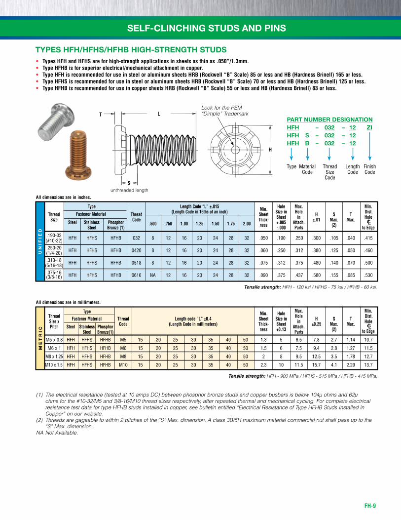
.190-32 hfh hfhs hfhb 032 8 12 16 20 24 28 32 .050 .190 .250 .300 .105 .040 .415 (#10-32) .250-20 hfh hfhs hfhb 0420 8 12 16 20 24 28 32 .060 .250 .312 .380 .125 .050 .460 (1/4-20) .313-18 hfh hfhs hfhb 0518 8 12 16 20 24 28 32 .075 .312 .375 .480 .140 .070 .500 (5/16-18) .375-16 hfh hfhs hfhb 0616 nA 12 16 20 24 28 32 .090 .375 .437 .580 .155 .085 .530 (3/8-16)
Tensile strength: HFH - 120 ksi / HFHS - 75 ksi / HFHB - 60 ksi.
Type
Length code “L” ±0.4
Min. Hole Max. Min. Thread Fastener Material
(Length Code in millimeters)
Sheet Size in Hole Dist. Size x Thread Thick- Sheet in H S T Hole Pitch Steel Stainless Phosphor Code ness +0.13 Attach. ±0.25 Max. Max. Steel Bronze(1) Parts (2) to Edge
M5 x 0.8 hfh hfhs hfhb M5 15 20 25 30 35 40 50 1.3 5 6.5 7.8 2.7 1.14 10.7
M6 x 1 hfh hfhs hfhb M6 15 20 25 30 35 40 50 1.5 6 7.5 9.4 2.8 1.27 11.5
M8 x 1.25 hfh hfhs hfhb M8 15 20 25 30 35 40 50 2 8 9.5 12.5 3.5 1.78 12.7
M10 x 1.5 hfh hfhs hfhb M10 15 20 25 30 35 40 50 2.3 10 11.5 15.7 4.1 2.29 13.7
Tensile strength: HFH - 900 MPa / HFHS - 515 MPa / HFHB - 415 MPa.
• Types HFH and HFHS are for high-strength applications in sheets as thin as .050”/1.3mm.• Type HFHB is for superior electrical/mechanical attachment in copper.• Type HFH is recommended for use in steel or aluminum sheets HRB (Rockwell “B” Scale) 85 or less and HB (Hardness Brinell) 165 or less.• Type HFHS is recommended for use in steel or aluminum sheets HRB (Rockwell “B” Scale) 70 or less and HB (Hardness Brinell) 125 or less.• Type HFHB is recommended for use in copper sheets HRB (Rockwell “B” Scale) 55 or less and HB (Hardness Brinell) 83 or less.
All dimensions are in inches.
All dimensions are in millimeters.
(1) The electrical resistance (tested at 10 amps DC) between phosphor bronze studs and copper busbars is below 104µ ohms and 62µ ohms for the #10-32/M5 and 3/8-16/M10 thread sizes respectively, after repeated thermal and mechanical cycling. For complete electrical resistance test data for type HFHB studs installed in copper, see bulletin entitled “Electrical Resistance of Type HFHB Studs Installed in Copper” on our website.
(2) Threads are gageable to within 2 pitches of the “S” Max. dimension. A class 3B/5H maximum material commercial nut shall pass up to the “S” Max. dimension.
NA Not Available.
TYPES HFH/HFHS/HFHB HIGH-STRENGTH STUDS
L
H
S
T
unthreaded length
Look for the PEM “Dimple” Trademark
Type
HFH – 032 – 12 ZIHFH S – 032 – 12HFH B – 032 – 12
LengthCode
ThreadsizeCode
finish Code
MaterialCode
PART NUMBER DESIGNATION
FH-10
SELF-CLINCHING STUDS AND PINSM
ET
RIC
UN
IFIE
D
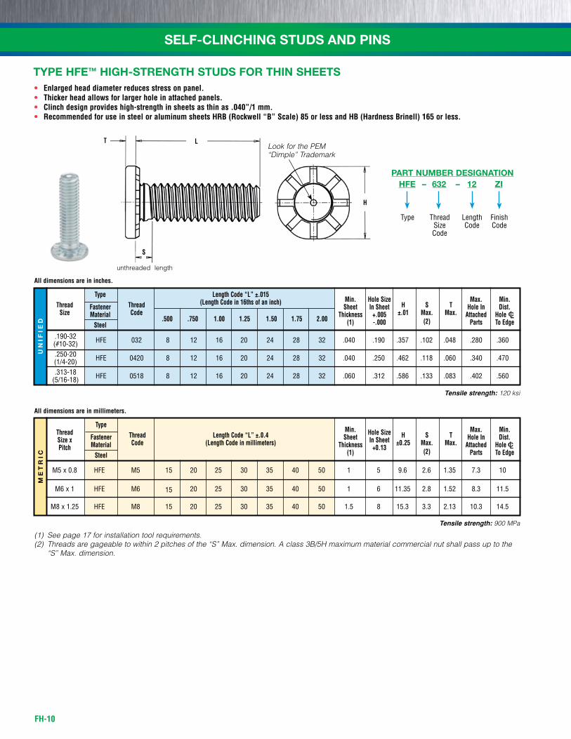
• Enlarged head diameter reduces stress on panel.• Thicker head allows for larger hole in attached panels.• Clinch design provides high-strength in sheets as thin as .040”/1 mm.• Recommended for use in steel or aluminum sheets HRB (Rockwell “B” Scale) 85 or less and HB (Hardness Brinell) 165 or less.
Type Thread Thread Length Code “L” ±.0.4 Min. Hole Size H S T Max. Min. Size x Fastener Code (Length Code in millimeters)
Sheet In Sheet ±0.25 Max. Max. Hole In Dist.
Pitch Material Thickness +0.13 Attached HoleC/L Steel (1) (2) Parts To Edge
M5 x 0.8 hfE M5 15 20 25 30 35 40 50 1 5 9.6 2.6 1.35 7.3 10
M6 x 1 hfE M6 15 20 25 30 35 40 50 1 6 11.35 2.8 1.52 8.3 11.5
M8 x 1.25 hfE M8 15 20 25 30 35 40 50 1.5 8 15.3 3.3 2.13 10.3 14.5
Type Length Code “L” ±.015 Thread Thread (Length Code in 16ths of an inch) Min. Hole Size H S T Max. Min. Size Fastener Code Sheet In Sheet ±.01 Max. Max.
Hole In Dist. Material Thickness +.005 Attached HoleC/L Steel (1) -.000 (2) Parts To Edge
.190-32 hfE 032 8 12 16 20 24 28 32 .040 .190 .357 .102 .048 .280 .360 (#10-32) .250-20 hfE 0420 8 12 16 20 24 28 32 .040 .250 .462 .118 .060 .340 .470 (1/4-20) .313-18 hfE 0518 8 12 16 20 24 28 32 .060 .312 .586 .133 .083 .402 .560 (5/16-18)
Tensile strength: 120 ksi
.500 .750 1.00 1.25 1.50 1.75 2.00
Tensile strength: 900 MPa
All dimensions are in inches.
All dimensions are in millimeters.
(1) See page 17 for installation tool requirements.(2) Threads are gageable to within 2 pitches of the “S” Max. dimension. A class 3B/5H maximum material commercial nut shall pass up to the
“S” Max. dimension.
TYPE HFE™ HIGH-STRENGTH STUDS FOR THIN SHEETS
T L
H
S
unthreaded length
Look for the PEM “Dimple” Trademark
Type
HFE – 632 – 12 ZI
LengthCode
ThreadsizeCode
finish Code
PART NUMBER DESIGNATION
FH-11
SELF-CLINCHING STUDS AND PINS
All dimensions are in inches.
All dimensions are in millimeters.
UN
IFIE
D
Thread Type Min. Hole Size Max. Hole S Min. Dist. Size Thread Sheet in Sheet in Attached H Max. T Hole C/L Steel Code .500 .750 1.00 Thickness +.005 –.000 Parts ±.01 (2) Max. To Edge .190-32
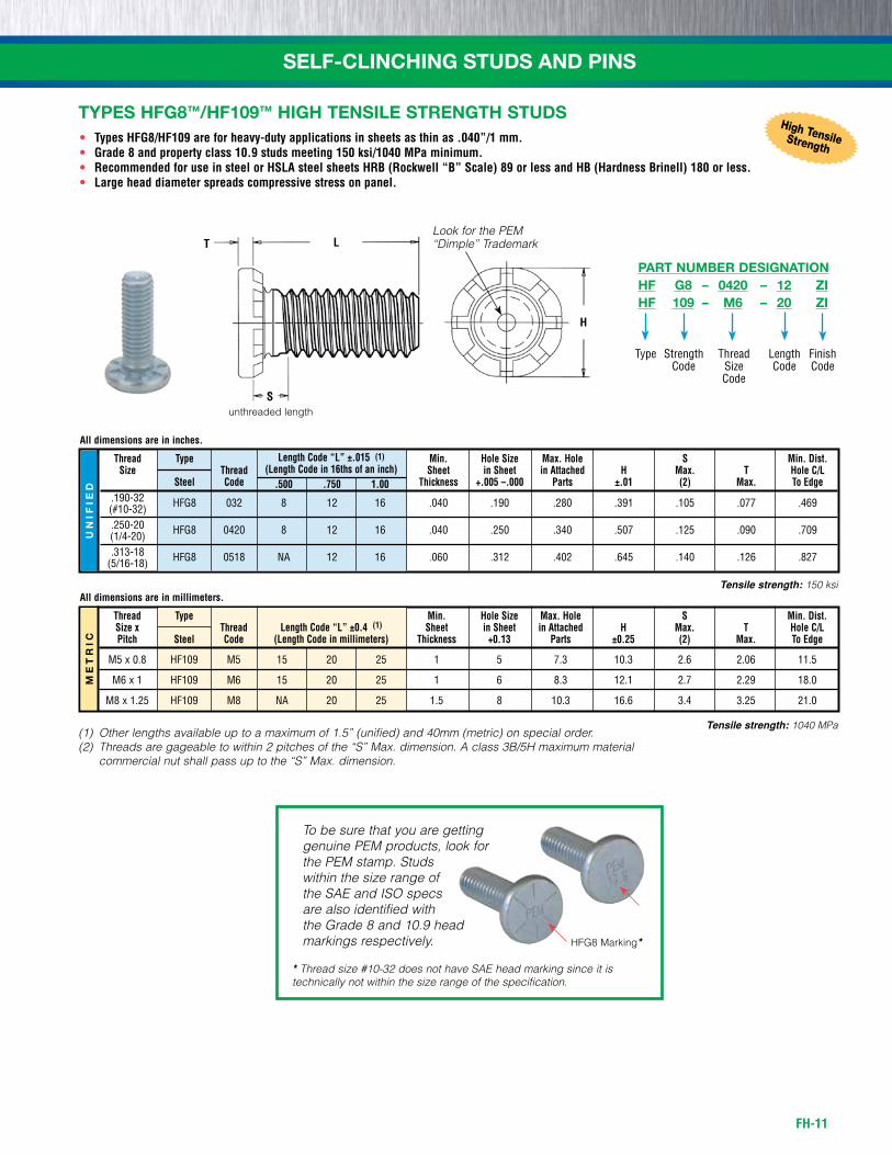
hfG8 032 8 12 16 .040 .190 .280 .391 .105 .077 .469 (#10-32) .250-20
hfG8 0420 8 12 16 .040 .250 .340 .507 .125 .090 .709 (1/4-20) .313-18
hfG8 0518 nA 12 16 .060 .312 .402 .645 .140 .126 .827 (5/16-18)
Length Code “L” ±.015 (1)
(Length Code in 16ths of an inch)
ME
TR
IC
Thread Type Min. Hole Size Max. Hole S Min. Dist. Size x Thread Sheet in Sheet in Attached H Max. T Hole C/L Pitch Steel Code Thickness +0.13 Parts ±0.25 (2) Max. To Edge
M5 x 0.8 hf109 M5 15 20 25 1 5 7.3 10.3 2.6 2.06 11.5
M6 x 1 hf109 M6 15 20 25 1 6 8.3 12.1 2.7 2.29 18.0
M8 x 1.25 hf109 M8 nA 20 25 1.5 8 10.3 16.6 3.4 3.25 21.0
Length Code “L” ±0.4 (1)
(Length Code in millimeters)
• Types HFG8/HF109 are for heavy-duty applications in sheets as thin as .040”/1 mm.• Grade 8 and property class 10.9 studs meeting 150 ksi/1040 MPa minimum.• Recommended for use in steel or HSLA steel sheets HRB (Rockwell “B” Scale) 89 or less and HB (Hardness Brinell) 180 or less.• Large head diameter spreads compressive stress on panel.
TYPES HFG8™/HF109™ HIGH TENSILE STRENGTH STUDS
HFG8 Marking*
To be sure that you are getting genuine PEM products, look for the PEM stamp. Studs within the size range of the SAE and ISO specs are also identified with the Grade 8 and 10.9 head markings respectively.
* Thread size #10-32 does not have SAE head marking since it is technically not within the size range of the specification.
High TensileStrength
(1) Other lengths available up to a maximum of 1.5” (unified) and 40mm (metric) on special order.(2) Threads are gageable to within 2 pitches of the “S” Max. dimension. A class 3B/5H maximum material
commercial nut shall pass up to the “S” Max. dimension.
L
H
S
T
unthreaded length
Look for the PEM “Dimple” Trademark
Type
HF G8 – 0420 – 12 ZIHF 109 – M6 – 20 ZI
LengthCode
ThreadsizeCode
finish Code
strengthCode
PART NUMBER DESIGNATION
Tensile strength: 150 ksi
Tensile strength: 1040 MPa
FH-12
SELF-CLINCHING STUDS AND PINSM
ET
RIC
UN
IFIE
D
Type Length Code “L” ±.015 Hole Min. Nominal Fastener Material Pin (Length Code in 16ths of an inch) Min. Size in Dist. Pin Dia. Sheet Sheet H S Hole Diameter Steel Stainless Alu- Code .250 .312 .375 .500 .625 .750 .875 1.00 1.25 1.50 Thick- +.003 ± .015 Max.
P±.002 Steel minum ness -.000 (1) to Edge
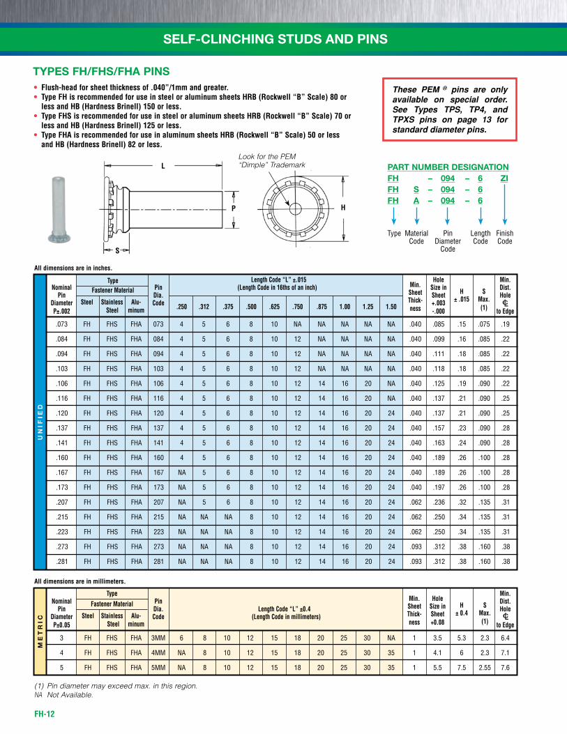
.073 fh fhs fhA 073 4 5 6 8 10 nA nA nA nA nA .040 .085 .15 .075 .19
.084 fh fhs fhA 084 4 5 6 8 10 12 nA nA nA nA .040 .099 .16 .085 .22
.094 fh fhs fhA 094 4 5 6 8 10 12 nA nA nA nA .040 .111 .18 .085 .22
.103 fh fhs fhA 103 4 5 6 8 10 12 nA nA nA nA .040 .118 .18 .085 .22
.106 fh fhs fhA 106 4 5 6 8 10 12 14 16 20 nA .040 .125 .19 .090 .22
.116 fh fhs fhA 116 4 5 6 8 10 12 14 16 20 nA .040 .137 .21 .090 .25
.120 fh fhs fhA 120 4 5 6 8 10 12 14 16 20 24 .040 .137 .21 .090 .25
.137 fh fhs fhA 137 4 5 6 8 10 12 14 16 20 24 .040 .157 .23 .090 .28
.141 fh fhs fhA 141 4 5 6 8 10 12 14 16 20 24 .040 .163 .24 .090 .28
.160 fh fhs fhA 160 4 5 6 8 10 12 14 16 20 24 .040 .189 .26 .100 .28
.167 fh fhs fhA 167 nA 5 6 8 10 12 14 16 20 24 .040 .189 .26 .100 .28
.173 fh fhs fhA 173 nA 5 6 8 10 12 14 16 20 24 .040 .197 .26 .100 .28
.207 fh fhs fhA 207 nA 5 6 8 10 12 14 16 20 24 .062 .236 .32 .135 .31
.215 fh fhs fhA 215 nA nA nA 8 10 12 14 16 20 24 .062 .250 .34 .135 .31
.223 fh fhs fhA 223 nA nA nA 8 10 12 14 16 20 24 .062 .250 .34 .135 .31
.273 fh fhs fhA 273 nA nA nA 8 10 12 14 16 20 24 .093 .312 .38 .160 .38
.281 fh fhs fhA 281 nA nA nA 8 10 12 14 16 20 24 .093 .312 .38 .160 .38
• Flush-head for sheet thickness of .040”/1mm and greater.• Type FH is recommended for use in steel or aluminum sheets HRB (Rockwell “B” Scale) 80 or
less and HB (Hardness Brinell) 150 or less.• Type FHS is recommended for use in steel or aluminum sheets HRB (Rockwell “B” Scale) 70 or
less and HB (Hardness Brinell) 125 or less.• Type FHA is recommended for use in aluminum sheets HRB (Rockwell “B” Scale) 50 or less
and HB (Hardness Brinell) 82 or less.
Type Min. Nominal Fastener Material Pin Min. Hole Dist. Pin Dia. Length Code “L” ±0.4 Sheet Size in H S Hole Diameter Steel Stainless Alu- Code (Length Code in millimeters) Thick- Sheet ± 0.4 Max.
P±0.05 Steel minum ness +0.08 (1) to Edge
3 fh fhs fhA 3MM 6 8 10 12 15 18 20 25 30 nA 1 3.5 5.3 2.3 6.4
4 fh fhs fhA 4MM nA 8 10 12 15 18 20 25 30 35 1 4.1 6 2.3 7.1
5 fh fhs fhA 5MM nA 8 10 12 15 18 20 25 30 35 1 5.5 7.5 2.55 7.6
(1) Pin diameter may exceed max. in this region.NA Not Available.
These PEM ® pins are only available on special order. See Types TPS, TP4, and TPXS pins on page 13 for standard diameter pins.
All dimensions are in inches.
All dimensions are in millimeters.
TYPES FH/FHS/FHA PINS
L
H
S
P
Look for the PEM “Dimple” Trademark
Type
FH – 094 – 6 ZIFH S – 094 – 6FH A – 094 – 6
LengthCode
PinDiameter
Code
finish Code
MaterialCode
PART NUMBER DESIGNATION
FH-13
SELF-CLINCHING STUDS AND PINSM
ET
RIC
UN
IFIE
D
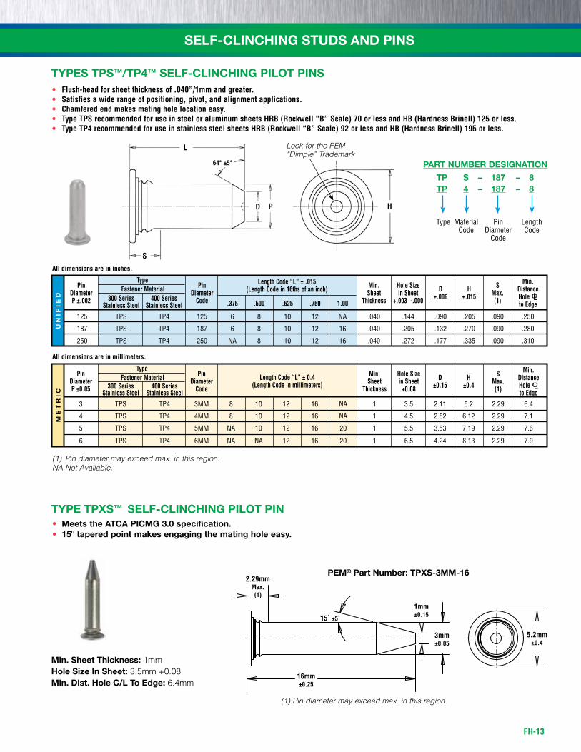
Type Min. Pin Fastener Material Pin Min. Hole Size D H S Distance Diameter 300 Series 400 Series Diameter Sheet in Sheet ±.006 ±.015 Max. HoleC/L P ±.002 Stainless Steel Stainless Steel
Code .375 .500 .625 .750 1.00 Thickness +.003 -.000 (1) to Edge
.125 TPs TP4 125 6 8 10 12 nA .040 .144 .090 .205 .090 .250
.187 TPs TP4 187 6 8 10 12 16 .040 .205 .132 .270 .090 .280
.250 TPs TP4 250 nA 8 10 12 16 .040 .272 .177 .335 .090 .310
Type Min. Pin Fastener Material Pin Min. Hole Size D H S Distance Diameter 300 Series 400 Series Diameter Sheet in Sheet ±0.15 ±0.4 Max. HoleC/L P ±0.05 Stainless Steel Stainless Steel Code Thickness +0.08 (1) to Edge
3 TPs TP4 3MM 8 10 12 16 nA 1 3.5 2.11 5.2 2.29 6.4
4 TPs TP4 4MM 8 10 12 16 nA 1 4.5 2.82 6.12 2.29 7.1
5 TPs TP4 5MM nA 10 12 16 20 1 5.5 3.53 7.19 2.29 7.6
6 TPs TP4 6MM nA nA 12 16 20 1 6.5 4.24 8.13 2.29 7.9
(1) Pin diameter may exceed max. in this region.NA Not Available.
• Flush-head for sheet thickness of .040”/1mm and greater.• Satisfies a wide range of positioning, pivot, and alignment applications.• Chamfered end makes mating hole location easy.• Type TPS recommended for use in steel or aluminum sheets HRB (Rockwell “B” Scale) 70 or less and HB (Hardness Brinell) 125 or less.• Type TP4 recommended for use in stainless steel sheets HRB (Rockwell “B” Scale) 92 or less and HB (Hardness Brinell) 195 or less.
All dimensions are in inches.
All dimensions are in millimeters.
• Meets the ATCA PICMG 3.0 specification.• 15˚ tapered point makes engaging the mating hole easy.
TYPE TPXS™ SELF-CLINCHING PILOT PIN
Min. Sheet Thickness: 1mmHole Size In Sheet: 3.5mm +0.08Min. Dist. Hole C/L To Edge: 6.4mm
Length Code “L” ± .015(Length Code in 16ths of an inch)
Length Code “L” ± 0.4(Length Code in millimeters)
TYPES TPS™/TP4™ SELF-CLINCHING PILOT PINS
H
L
64° ±5°
S
PD
Look for the PEM “Dimple” Trademark
(1) Pin diameter may exceed max. in this region.
1mm±0.15
3mm±0.05
5.2mm±0.4
16mm±0.25
15˚ ±5˚
2.29mmMax.(1)
PEM® Part Number: TPXS-3MM-16
Type
TP S – 187 – 8TP 4 – 187 – 8
LengthCode
PinDiameter
Code
MaterialCode
PART NUMBER DESIGNATION
FH-14
SELF-CLINCHING STUDS AND PINSU
NIF
IED
ME
TR
IC
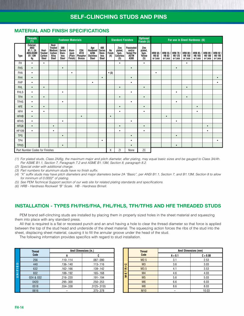
INSTALLATION - TYPES FH/FHS/FHA, FHL/FHLS, TFH/TFHS AND HFE THREADED STUDS
PEM brand self-clinching studs are installed by placing them in properly sized holes in the sheet material and squeezing them into place with any standard press. All that is required is a flat or recessed punch and an anvil having a hole to clear the thread diameter so that force is applied between the top of the stud head and underside of the sheet material. The squeezing action forces the ribs of the stud into the sheet, displacing sheet material, causing it to fill the annular groove under the head of the stud. The following information provides specifics with regard to stud installation.
Thread Anvil Dimensions (in.)
Code A C 256 .110-.114 .087-.090 440 .136-.140 .113-.116 632 .162-.166 .139-.142 832 .188-.192 .165-.168 024 & 032 .216-.220 .191-.194 0420 .295-.300 .250-.253 0518 .334-.338 .3125-.3155 0616 – .375-.378
Thread Anvil Dimensions (mm)
Code A + 0.1 C + 0.08 M2.5 3.1 2.53 M3 3.6 3.03 M3.5 4.1 3.53 M4 4.6 4.03 M5 5.6 5.03 M6 6.6 6.03 M8 8.6 8.03 M10 – 10.03
(1) For plated studs, Class 2A/6g, the maximum major and pitch diameter, after plating, may equal basic sizes and be gauged to Class 3A/4h. Per ASME B1.1, Section 7, Paragraph 7.2 and ASME B1.13M, Section 8, paragraph 8.2.
(2) Special order with additional charge.(3) Part numbers for aluminum studs have no finish suffix.(4) “X” suffix studs may have pitch diameters and major diameters below 2A “Basic”, per ANSI B1.1, Section 7, and B1.13M, Section 8 to allow
for minimum of 0.0002” of plating.(5) See PEM Technical Support section of our web site for related plating standards and specifications.(6) HRB - Hardness Rockwell “B” Scale. HB - Hardness Brinell.
Threads Fastener Materials Standard Finishes Optional For use in Sheet Hardness: (6) (1) Finish (2)
MATERIAL AND FINISH SPECIFICATIONS
External, Heat- ANSI Treated 300 Age 400 Zinc Passivated Zinc B1.1, 2A Heat- Medium Series Alum- CDA Hardened Series No plated, and/or plated, ANSI/ASME Treated Carbon Stain- inum #510 A286 Stain- Finish 5µm, Tested Per 5µm, HRB 50 / HRB 55 / HRB 70 / HRB 80 / HRB 85 / HRB 89 / HRB 92 / Type B1.13M Carbon Alloy less (Plain Phosphor Stainless less (4) Colorless ASTM Yellow HB 82 HB 83 HB 125 HB 150 HB 165 HB 180 HB 195 6g Steel Steel Steel Finish) Bronze Steel Steel (5) A380 (5) or Less or Less or Less or Less or Less or Less or Less
fh • • • • •
fhs • • • •
fha • • • (3) •
fh4 • • • •
fhP • • • •
fhL • • • • •
fhLs • • • •
tfh • • • • •
tfhs • • • •
hfE • • • • •
hfh • • • • •
hfhb • • • •
hfhs • • • •
hfG8 • • • • •
hf109 • • • • •
tPs • • •
tP4 • • •
tPXs • • •
Part number Codes for finishes x zi none zC
FH-15
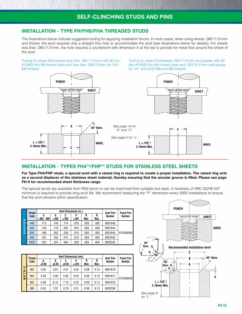
INSTALLATION - TYPE FH/FHS/FHA THREADED STUDS
The illustrations below indicate suggested tooling for applying installation forces. In most cases, when using sheets .060”/1.51mm and thicker, the anvil requires only a straight thru hole to accommodate the stud (see illustrations below for details). For sheets less than .060 /1.51mm, the hole requires a countersink with dimension A at the top to provide for metal flow around the shank of the stud.
Tooling for sheet thicknesses less than .060 /1.51mm with #2 thru #10/M3 thru M5 thread sizes and less than .093 /2.4mm for 1/4”/M6 threads.
Tooling for sheet thicknesses .060”/1.51mm and greater with #2 thru #10/M3 thru M5 thread sizes and .093”/2.41mm and greater for 1/4” and 5/16”/M6 and M8 threads.
A
C
L +.125”/3.18mm Min.
45° Nom.
SHEET
PUNCH
ANVIL
SELF-CLINCHING STUDS AND PINS
INSTALLATION - TYPES FH4™/FHP™ STUDS FOR STAINLESS STEEL SHEETSFor Type FH4/FHP studs, a special anvil with a raised ring is required to create a proper installation. The raised ring acts as a second displacer of the stainless sheet material, thereby ensuring that the annular groove is filled. Please see page FH-6 for recommended sheet thickness range.
The special anvils are available from PEM stock or can be machined from suitable tool steel. A hardness of HRC 55/HB 547 minimum is required to provide long anvil life. We recommend measuring the “P” dimension every 5000 installations to ensure that the anvil remains within specification.
PUNCH
SHEET
ANVIL
See page 14 for “A” and “C”. C
SHEET
PUNCH
ANVIL L +.125”/3.18mm Min.
ME
TR
ICU
NIF
IED
Thread Anvil Dimensions (in.) Anvil Part Punch Part Code A B C P R1 R2 Number Number +.003 -.000 ±.002 ±.002 ±.001 Max. Max.
440 .113 .144 .174 .010 .003 .005 8001645
632 .140 .170 .200 .010 .003 .005 8001644
832 .166 .202 .236 .010 .003 .005 8001643 975200048
032 .191 .235 .275 .010 .003 .005 8001642
0420 .252 .324 .360 .020 .003 .005 8002535
Thread Anvil Dimensions (mm) Anvil Part Punch Part Code A B C P R1 R2 Number Number +0.08 ±0.05 ±0.05 ±.025 Max. Max.
M3 3.05 3.81 4.57 0.25 0.08 0.13 8001678
M4 4.04 4.95 5.82 0.25 0.08 0.13 8001677 975200048
M5 5.08 6.15 7.16 0.25 0.08 0.13 8001676
M6 6.05 7.87 8.79 0.51 0.08 0.13 8002536
Recommended Installation Anvil
C
B
A
P
95°Nom.
R1
R2
L +.125”/3.18mm Min.
45° Nom.
95°Nom.
R1
R2
See page 6for “L”.
See page 5 for “L”.
FH-16
SELF-CLINCHING STUDS AND PINS
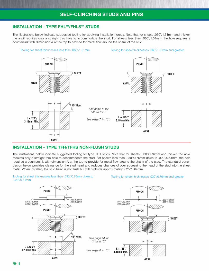
INSTALLATION - TYPE FHL™/FHLS™ STUDS
The illustrations below indicate suggested tooling for applying installation forces. Note that for sheets .060”/1.51mm and thicker, the anvil requires only a straight thru hole to accommodate the stud. For sheets less than .060”/1.51mm, the hole requires a countersink with dimension A at the top to provide for metal flow around the shank of the stud.
Tooling for sheet thicknesses less than .060”/1.51mm. Tooling for sheet thicknesses .060”/1.51mm and greater.
INSTALLATION - TYPE TFH/TFHS NON-FLUSH STUDS
The illustrations below indicate suggested tooling for type TFH studs. Note that for sheets .030”/0.76mm and thicker, the anvil requires only a straight thru hole to accommodate the stud. For sheets less than .030”/0.76mm down to .020”/0.51mm, the hole requires a countersink with dimension A at the top to provide for metal flow around the shank of the stud. The standard punch design below provides clearance for the stud head and reduces chances of over squeezing the head of the stud into the sheet metal. When installed, the stud head is not flush but will protrude approximately .025”/0.64mm.
Tooling for sheet thicknesses less than .030”/0.76mm down to .020”/0.51mm.
Tooling for sheet thicknesses .030”/0.76mm and greater.
A
C
SHEET
PUNCH
ANVIL
ANVIL
L +.125”/3.18mm Min.
45° Nom. C
PUNCH
ANVIL
ANVIL
SHEET
L +.125”/3.18mm Min.
PUNCH
PUNCH
ANVIL
A
C
h +.015”/+0.4mm+.025”/+0.6mm
.020”/0.51mm
.021”/0.53mm
SHEET
L +.125”/3.18mm Min.
45° Nom.
PUNCH
PUNCH
ANVIL
C
h +.015”/+0.4mm+.025”/+0.6mm
.020”/0.51mm
.021”/0.53mm
SHEET
L +.125”/3.18mm Min.
See page 14 for “A” and “C”.
See page 14 for “A” and “C”.
See page 7 for “L”.
See page 8 for “L”.
FH-17
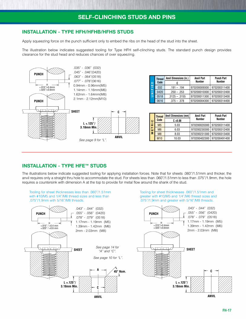
INSTALLATION - TYPE HFE™ STUDS
The illustrations below indicate suggested tooling for applying installation forces. Note that for sheets .060”/1.51mm and thicker, the anvil requires only a straight thru hole to accommodate the stud. For sheets less than .060”/1.51mm to less than .075”/1.9mm, the hole requires a countersink with dimension A at the top to provide for metal flow around the shank of the stud.
Tooling for sheet thicknesses less than .060”/1.51mm with #10/M5 and 1/4”/M6 thread sizes and less than .075”/1.9mm with 5/16”/M8 threads.
Tooling for sheet thicknesses .060”/1.51mm and greater with #10/M5 and 1/4”/M6 thread sizes and .075”/1.9mm and greater with 5/16”/M8 threads.
SHEET
.043” - .044” (032)
.055” - .056” (0420)
.078” - .079” (0518) 1.17mm - 1.19mm (M5)1.39mm - 1.42mm (M6)2mm - 2.03mm (M8)
h+.015” / +0.4 mm+.025” / +0.6 mm
PUNCH
SHEET
.043” - .044” (032)
.055” - .056” (0420)
.078” - .079” (0518) 1.17mm - 1.19mm (M5)1.39mm - 1.42mm (M6)2mm - 2.03mm (M8)
h+.015”/+0.4mm+.025”/+0.6mm
PUNCH
SELF-CLINCHING STUDS AND PINS
INSTALLATION - TYPE HFH/HFHB/HFHS STUDS
Apply squeezing force on the punch sufficient only to embed the ribs on the head of the stud into the sheet.
The illustration below indicates suggested tooling for Type HFH self-clinching studs. The standard punch design provides clearance for the stud head and reduces chances of over squeezing.
h+.015”/+0.4mm+.025”/+0.6mm
PUNCH
PUNCH
SHEET
.035” - .036” (032)
.045” - .046” (0420)
.063” - .064” (0518)
.077” - .078” (0616)0.94mm - 0.96mm (M5)1.14mm - 1.16mm (M6)1.62mm - 1.64mm (M8)2.1mm - 2.12mm (M10)
UN
IFIE
D
Thread Anvil Dimensions (in.) Anvil Part Punch Part
Code C Number Number
032 .191 – .194 970200009300 970200311400 0420 .250 – .253 970200010300 970200312400 0518 .3125 – .3155 970200011300 970200313400 0616 .375 – .378 970200004300 970200314400
ME
TR
IC
Thread Anvil Dimensions (mm) Anvil Part Punch Part
Code C +0.08 Number Number
M5 5.03 970200020300 970200311400 M6 6.03 970200230300 970200312400 M8 8.03 970200231300 970200313400 M10 10.03 970200402300 970200491400
C
ANVIL
L +.125”/3.18mm Min.
A
C
ANVIL
L +.125”/3.18mm Min.
45° Nom. C
ANVIL
L +.125”/3.18mm Min.
See page 14 for “A” and “C”.
See page 10 for “L”.
See page 9 for “L”.
FH-18
SELF-CLINCHING STUDS AND PINS
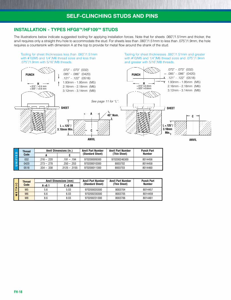
INSTALLATION - TYPES HFG8™/HF109™ STUDS
The illustrations below indicate suggested tooling for applying installation forces. Note that for sheets .060”/1.51mm and thicker, the anvil requires only a straight thru hole to accommodate the stud. For sheets less than .060”/1.51mm to less than .075”/1.9mm, the hole requires a countersink with dimension A at the top to provide for metal flow around the shank of the stud.
Tooling for sheet thicknesses less than .060”/1.51mm with #10/M5 and 1/4”/M6 thread sizes and less than .075”/1.9mm with 5/16”/M8 threads.
Tooling for sheet thicknesses .060”/1.51mm and greater with #10/M5 and 1/4”/M6 thread sizes and .075”/1.9mm and greater with 5/16”/M8 threads.
SHEET
.072” - .073” (032)
.085” - .086” (0420)
.121” - .122” (0518)1.93mm - 1.95mm (M5)2.16mm - 2.18mm (M6)3.12mm - 3.14mm (M8)
H+.015” / +0.4 mm+.025” / +0.6 mm
PUNCH
SHEET
.072” - .073” (032)
.085” - .086” (0420)
.121” - .122” (0518)1.93mm - 1.95mm (M5)2.16mm - 2.18mm (M6)3.12mm - 3.14mm (M8)
H+.015”/+0.4mm+.025”/+0.6mm
PUNCH
UN
IFIE
D
Thread Anvil Dimensions (in.) Anvil Part Number Anvil Part Number Punch Part
Code A C (Standard Sheet) (Thin Sheet) Number
032 .216 – .220 .191 – .194 970200009300 970200246300 8014456 0420 .273 – .278 .250 – .253 970200010300 8003702 8014458 0518 .334 – .338 .3125 – .3155 970200011300 8003703 8014460
ME
TR
IC
Thread Anvil Dimensions (mm) Anvil Part Number Anvil Part Number Punch Part
Code A +0.1 C +0.08 (Standard Sheet) (Thin Sheet) Number
M5 5.6 5.03 970200020300 8003704 8014457 M6 6.6 6.03 970200230300 8003705 8014459 M8 8.6 8.03 970200231300 8003706 8014461
A
C
ANVIL
L +.125”/3.18mm Min.
45° Nom. C
ANVIL
L +.125”/3.18mm
Min.
See page 11 for “L”.
FH-19
SELF-CLINCHING STUDS AND PINS
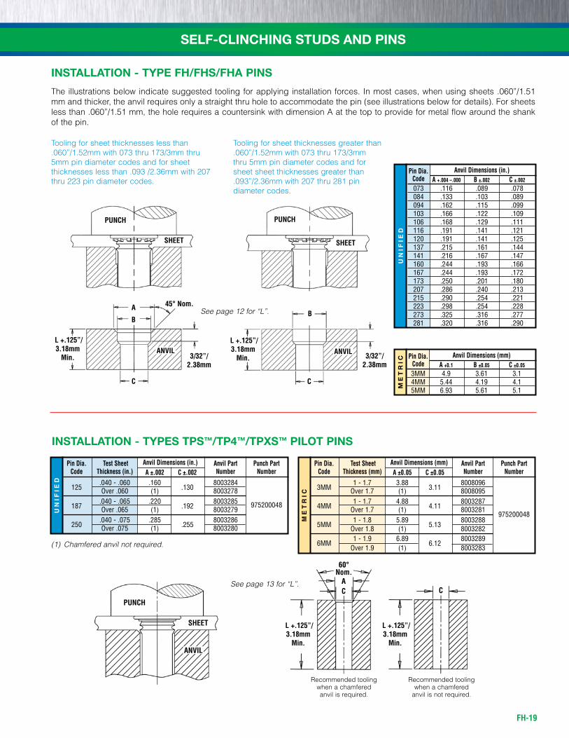
INSTALLATION - TYPES TPS™/TP4™/TPXS™ PILOT PINS
PUNCH
SHEET
ANVIL
(1) Chamfered anvil not required.
INSTALLATION - TYPE FH/FHS/FHA PINS
The illustrations below indicate suggested tooling for applying installation forces. In most cases, when using sheets .060”/1.51 mm and thicker, the anvil requires only a straight thru hole to accommodate the pin (see illustrations below for details). For sheets less than .060”/1.51 mm, the hole requires a countersink with dimension A at the top to provide for metal flow around the shank of the pin.
Tooling for sheet thicknesses less than .060”/1.52mm with 073 thru 173/3mm thru 5mm pin diameter codes and for sheet thicknesses less than .093 /2.36mm with 207 thru 223 pin diameter codes.
Tooling for sheet thicknesses greater than .060”/1.52mm with 073 thru 173/3mm thru 5mm pin diameter codes and for sheet sheet thicknesses greater than .093”/2.36mm with 207 thru 281 pin diameter codes.
UN
IFIE
D
Pin Dia. Anvil Dimensions (in.)
Code A +.004 –.000 B ±.002 C ±.002
073 .116 .089 .078 084 .133 .103 .089 094 .162 .115 .099 103 .166 .122 .109 106 .168 .129 .111 116 .191 .141 .121 120 .191 .141 .125 137 .215 .161 .144 141 .216 .167 .147 160 .244 .193 .166 167 .244 .193 .172 173 .250 .201 .180 207 .286 .240 .213 215 .290 .254 .221 223 .298 .254 .228 273 .325 .316 .277 281 .320 .316 .290
ME
TR
IC
Pin Dia. Anvil Dimensions (mm)
Code A +0.1 B ±0.05 C ±0.05
3MM 4.9 3.61 3.1 4MM 5.44 4.19 4.1 5MM 6.93 5.61 5.1
A
C
SHEET
PUNCH
ANVIL
B
3/32”/2.38mm
L +.125”/3.18mm
Min.
45° Nom.
C
SHEET
PUNCH
ANVIL
B
3/32”/2.38mm
L +.125”/3.18mm
Min.
60°Nom.
AC C
Recommended tooling when a chamfered anvil is required.
Recommended tooling when a chamfered
anvil is not required.
L +.125”/3.18mm
Min.
L +.125”/3.18mm
Min.
See page 12 for “L”.
See page 13 for “L”.
UN
IFIE
D
Pin Dia. Test Sheet Anvil Dimensions (in.) Anvil Part Punch Part Code Thickness (in.) A ±.002 C ±.002 Number Number
125
.040 - .060 .160 .130
8003284 Over .060 (1) 8003278
187 .040 - .065 .220
.192 8003285 975200048
Over .065 (1) 8003279
250 .040 - .075 .285
.255 8003286
Over .075 (1) 8003280
ME
TR
IC
Pin Dia. Test Sheet Anvil Dimensions (mm) Anvil Part Punch Part Code Thickness (mm) A ±0.05 C ±0.05 Number Number
3MM
1 - 1.7 3.88 3.11
8008096 Over 1.7 (1) 8008095
4MM 1 - 1.7 4.88
4.11 8003287
Over 1.7 (1) 8003281 975200048
5MM
1 - 1.8 5.89 5.13
8003288 Over 1.8 (1) 8003282
6MM 1 - 1.9 6.89
6.12 8003289
Over 1.9 (1) 8003283
FH-20
SELF-CLINCHING STUDS AND PINSU
NIF
IED
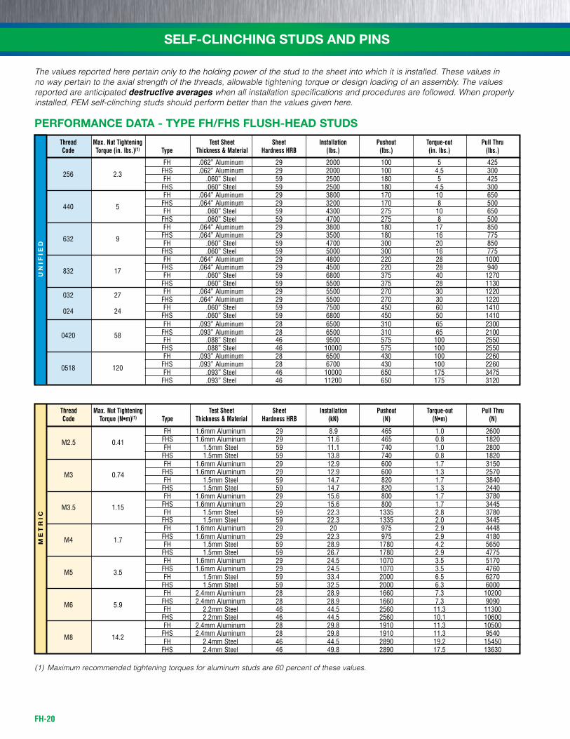
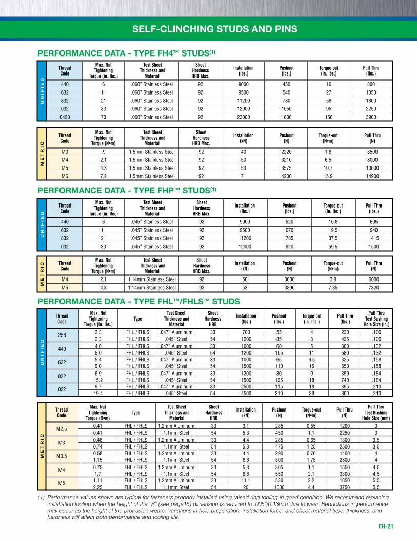
The values reported here pertain only to the holding power of the stud to the sheet into which it is installed. These values in no way pertain to the axial strength of the threads, allowable tightening torque or design loading of an assembly. The values reported are anticipated destructive averages when all installation specifications and procedures are followed. When properly installed, PEM self-clinching studs should perform better than the values given here.
PERFORMANCE DATA - TYPE FH/FHS FLUSH-HEAD STUDS
Thread Max. Nut Tightening Test Sheet Sheet Installation Pushout Torque-out Pull Thru Code Torque (in. lbs.)(1) Type Thickness & Material Hardness HRB (lbs.) (lbs.) (in. lbs.) (lbs.)
fh .062” Aluminum 29 2000 100 5 425 256 2.3 fhs .062” Aluminum 29 2000 100 4.5 300 fh .060” steel 59 2500 180 5 425 fhs .060” steel 59 2500 180 4.5 300 fh .064” Aluminum 29 3800 170 10 650 440 5 fhs .064” Aluminum 29 3200 170 8 500 fh .060” steel 59 4300 275 10 650 fhs .060” steel 59 4700 275 8 500 fh .064” Aluminum 29 3800 180 17 850 632 9 fhs .064” Aluminum 29 3500 180 16 775 fh .060” steel 59 4700 300 20 850 fhs .060” steel 59 5000 300 16 775 fh .064” Aluminum 29 4800 220 28 1000 832 17 fhs .064” Aluminum 29 4500 220 28 940 fh .060” steel 59 6800 375 40 1270 fhs .060” steel 59 5500 375 28 1130 032 27 fh .064” Aluminum 29 5500 270 30 1220 fhs .064” Aluminum 29 5500 270 30 1220 024 24 fh .060” steel 59 7500 450 60 1410 fhs .060” steel 59 6800 450 50 1410 fh .093” Aluminum 28 6500 310 65 2300 0420 58 fhs .093” Aluminum 28 6500 310 65 2100 fh .088” steel 46 9500 575 100 2550 fhs .088” steel 46 10000 575 100 2550 fh .093” Aluminum 28 6500 430 100 2260 0518 120 fhs .093” Aluminum 28 6700 430 100 2260 fh .093” steel 46 10000 650 175 3475 fhs .093” steel 46 11200 650 175 3120
(1) Maximum recommended tightening torques for aluminum studs are 60 percent of these values.
ME
TR
IC
Thread Max. Nut Tightening Test Sheet Sheet Installation Pushout Torque-out Pull Thru Code Torque (N•m)(1) Type Thickness & Material Hardness HRB (kN) (N) (N•m) (N)
fh 1.6mm Aluminum 29 8.9 465 1.0 2600 M2.5 0.41 fhs 1.6mm Aluminum 29 11.6 465 0.8 1820 fh 1.5mm steel 59 11.1 740 1.0 2800 fhs 1.5mm steel 59 13.8 740 0.8 1820 fh 1.6mm Aluminum 29 12.9 600 1.7 3150 M3 0.74 fhs 1.6mm Aluminum 29 12.9 600 1.3 2570 fh 1.5mm steel 59 14.7 820 1.7 3840 fhs 1.5mm steel 59 14.7 820 1.3 2440 fh 1.6mm Aluminum 29 15.6 800 1.7 3780 M3.5 1.15 fhs 1.6mm Aluminum 29 15.6 800 1.7 3445 fh 1.5mm steel 59 22.3 1335 2.8 3780 fhs 1.5mm steel 59 22.3 1335 2.0 3445 fh 1.6mm Aluminum 29 20 975 2.9 4448 M4 1.7 fhs 1.6mm Aluminum 29 22.3 975 2.9 4180 fh 1.5mm steel 59 28.9 1780 4.2 5650 fhs 1.5mm steel 59 26.7 1780 2.9 4775 fh 1.6mm Aluminum 29 24.5 1070 3.5 5170 M5 3.5 fhs 1.6mm Aluminum 29 24.5 1070 3.5 4760 fh 1.5mm steel 59 33.4 2000 6.5 6270 fhs 1.5mm steel 59 32.5 2000 6.3 6000 fh 2.4mm Aluminum 28 28.9 1660 7.3 10200 M6 5.9 fhs 2.4mm Aluminum 28 28.9 1660 7.3 9090 fh 2.2mm steel 46 44.5 2560 11.3 11300 fhs 2.2mm steel 46 44.5 2560 10.1 10600 fh 2.4mm Aluminum 28 29.8 1910 11.3 10500 M8 14.2 fhs 2.4mm Aluminum 28 29.8 1910 11.3 9540 fh 2.4mm steel 46 44.5 2890 19.2 15450 fhs 2.4mm steel 46 49.8 2890 17.5 13630
FH-21
SELF-CLINCHING STUDS AND PINSM
ET
RIC
UN
IFIE
DM
ET
RIC
UN
IFIE
D
PERFORMANCE DATA - TYPE FH4™ STUDS(1)
Max. Nut Test Sheet Sheet Thread Tightening Thickness and Hardness Installation Pushout Torque-out Pull Thru
Code Torque (in. lbs.) Material HRB Max. (lbs.) (lbs.) (in. lbs.) (lbs.)
440 6 .060” stainless steel 92 9000 450 16 800
632 11 .060” stainless steel 92 9500 540 27 1350
832 21 .060” stainless steel 92 11200 780 58 1800
032 33 .060” stainless steel 92 12000 1050 95 2250
0420 70 .060” stainless steel 92 23000 1600 156 3900
(1) Performance values shown are typical for fasteners properly installed using raised ring tooling in good condition. We recommend replacing installation tooling when the height of the “P” (see page15) dimension is reduced to .005”/0.13mm due to wear. Reductions in performance may occur as the height of the protrusion wears. Variations in hole preparation, installation force, and sheet material type, thickness, and hardness will affect both performance and tooling life.
Max. Nut Test Sheet Sheet Thread Tightening Thickness and Hardness Installation Pushout Torque-out Pull Thru
Code Torque (N•m) Material HRB Max. (kN) (N) (N•m) (N)
M3 .9 1.5mm stainless steel 92 40 2220 1.8 3500
M4 2.1 1.5mm stainless steel 92 50 3210 6.5 8000
M5 4.3 1.5mm stainless steel 92 53 3575 10.7 10000
M6 7.2 1.5mm stainless steel 92 71 4200 15.9 14900
PERFORMANCE DATA - TYPE FHP™ STUDS(1)
Max. Nut Test Sheet Sheet Thread Tightening Thickness and Hardness Installation Pushout Torque-out Pull Thru
Code Torque (in. lbs.) Material HRB Max. (lbs.) (lbs.) (in. lbs.) (lbs.)
440 6 .045” stainless steel 92 9000 520 10.6 605
632 11 .045” stainless steel 92 9500 670 19.5 940
832 21 .045” stainless steel 92 11200 785 37.5 1415
032 33 .045” stainless steel 92 12000 920 59.5 1500
Max. Nut Test Sheet Sheet Thread Tightening Thickness and Hardness Installation Pushout Torque-out Pull Thru
Code Torque (N•m) Material HRB Max. (kN) (N) (N•m) (N)
M4 2.1 1.14mm stainless steel 92 50 3000 3.9 6000
M5 4.3 1.14mm stainless steel 92 53 3890 7.35 7320
ME
TR
ICU
NIF
IED
PERFORMANCE DATA - TYPE FHL™/FHLS™ STUDS Max. Nut Test Sheet Sheet Pull Thru Thread Tightening Type Thickness and Hardness Installation Pushout Torque-out Pull Thru Test Bushing Code Torque (in. lbs.) Material HRB (lbs.) (lbs.) (in. lbs.) (lbs.) Hole Size (in.)
256 2.3 fhL / fhLs .047” Aluminum 33 700 55 4 230 .106 2.3 fhL / fhLs .045” steel 54 1200 85 8 425 .106 440 4.0 fhL / fhLs .047” Aluminum 33 1000 60 5 300 .132 5.0 fhL / fhLs .045” steel 54 1200 105 11 580 .132 632 5.4 fhL / fhLs .047” Aluminum 33 1000 65 6.5 325 .158 9.0 fhL / fhLs .045” steel 54 1500 110 15 650 .158 832 6.9 fhL / fhLs .047” Aluminum 33 1200 80 9 350 .184 15.2 fhL / fhLs .045” steel 54 1500 125 18 740 .184 032 9.7 fhL / fhLs .047” Aluminum 33 2500 115 18 395 .210 19.4 fhL / fhLs .045” steel 54 4500 210 38 800 .210
Max. Nut Test Sheet Sheet Pull Thru Thread Tightening Type Thickness and Hardness Installation Pushout Torque-out Pull Thru Test Bushing Code Torque (N•m) Material HRB (kN) (N) (N•m) (N) Hole Size (mm)
M2.5 0.41 fhL / fhLs 1.2mm Aluminum 33 3.1 285 0.55 1200 3 0.41 fhL / fhLs 1.1mm steel 54 5.3 450 1.1 2250 3 M3 0.46 fhL / fhLs 1.2mm Aluminum 33 4.4 285 0.65 1300 3.5 0.74 fhL / fhLs 1.1mm steel 54 5.3 475 1.25 2500 3.5 M3.5 0.58 fhL / fhLs 1.2mm Aluminum 33 4.4 290 0.76 1400 4 1.15 fhL / fhLs 1.1mm steel 54 6.6 500 1.75 2800 4 M4 0.75 fhL / fhLs 1.2mm Aluminum 33 5.3 365 1.1 1550 4.5 1.7 fhL / fhLs 1.1mm steel 54 6.6 550 2.1 3300 4.5 M5 1.11 fhL / fhLs 1.2mm Aluminum 33 11.1 530 2.2 1850 5.5 2.25 fhL / fhLs 1.1mm steel 54 20 1000 4.4 3750 5.5
FH-22
SELF-CLINCHING STUDS AND PINSM
ET
RIC
UN
IFIE
D
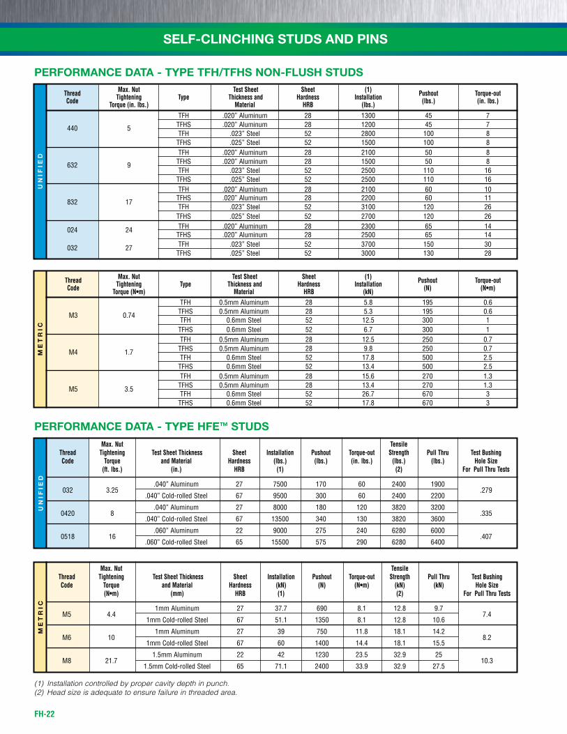
Max. Nut Test Sheet Sheet (1) Thread Tightening Type Thickness and Hardness Installation Pushout Torque-out
Code Torque (in. lbs.) Material HRB (lbs.) (lbs.) (in. lbs.)
Tfh .020” Aluminum 28 1300 45 7 440 5 Tfhs .020” Aluminum 28 1200 45 7 Tfh .023” steel 52 2800 100 8 Tfhs .025” steel 52 1500 100 8 Tfh .020” Aluminum 28 2100 50 8 632 9 Tfhs .020” Aluminum 28 1500 50 8 Tfh .023” steel 52 2500 110 16 Tfhs .025” steel 52 2500 110 16 Tfh .020” Aluminum 28 2100 60 10 832 17 Tfhs .020” Aluminum 28 2200 60 11 Tfh .023” steel 52 3100 120 26 Tfhs .025” steel 52 2700 120 26 024 24 Tfh .020” Aluminum 28 2300 65 14 Tfhs .020” Aluminum 28 2500 65 14 032 27 Tfh .023” steel 52 3700 150 30 Tfhs .025” steel 52 3000 130 28
Max. Nut Test Sheet Sheet (1) Thread Tightening Type Thickness and Hardness Installation Pushout Torque-out
Code Torque (N•m) Material HRB (kN) (N) (N•m)
Tfh 0.5mm Aluminum 28 5.8 195 0.6 M3 0.74 Tfhs 0.5mm Aluminum 28 5.3 195 0.6 Tfh 0.6mm steel 52 12.5 300 1 Tfhs 0.6mm steel 52 6.7 300 1 Tfh 0.5mm Aluminum 28 12.5 250 0.7 M4 1.7 Tfhs 0.5mm Aluminum 28 9.8 250 0.7 Tfh 0.6mm steel 52 17.8 500 2.5 Tfhs 0.6mm steel 52 13.4 500 2.5 Tfh 0.5mm Aluminum 28 15.6 270 1.3 M5 3.5 Tfhs 0.5mm Aluminum 28 13.4 270 1.3 Tfh 0.6mm steel 52 26.7 670 3 Tfhs 0.6mm steel 52 17.8 670 3
PERFORMANCE DATA - TYPE TFH/TFHS NON-FLUSH STUDS
ME
TR
ICU
NIF
IED
(1) Installation controlled by proper cavity depth in punch.(2) Head size is adequate to ensure failure in threaded area.
Max. Nut Tensile Thread Tightening Test Sheet Thickness Sheet Installation Pushout Torque-out Strength Pull Thru Test Bushing Code Torque and Material Hardness (kN) (N) (N•m) (kN) (kN) Hole Size (N•m) (mm) HRB (1) (2) For Pull Thru Tests
M5 4.4
1mm Aluminum 27 37.7 690 8.1 12.8 9.7 7.4
1mm Cold-rolled steel 67 51.1 1350 8.1 12.8 10.6
M6 10
1mm Aluminum 27 39 750 11.8 18.1 14.2 8.2
1mm Cold-rolled steel 67 60 1400 14.4 18.1 15.5
M8 21.7
1.5mm Aluminum 22 42 1230 23.5 32.9 25 10.3
1.5mm Cold-rolled steel 65 71.1 2400 33.9 32.9 27.5
Max. Nut Tensile Thread Tightening Test Sheet Thickness Sheet Installation Pushout Torque-out Strength Pull Thru Test Bushing Code Torque and Material Hardness (lbs.) (lbs.) (in. lbs.) (lbs.) (lbs.) Hole Size (ft. lbs.) (in.) HRB (1) (2) For Pull Thru Tests
032 3.25
.040” Aluminum 27 7500 170 60 2400 1900 .279
.040” Cold-rolled steel 67 9500 300 60 2400 2200
0420 8
.040” Aluminum 27 8000 180 120 3820 3200 .335
.040” Cold-rolled steel 67 13500 340 130 3820 3600
0518 16
.060” Aluminum 22 9000 275 240 6280 6000 .407
.060” Cold-rolled steel 65 15500 575 290 6280 6400
PERFORMANCE DATA - TYPE HFE™ STUDS
FH-23
SELF-CLINCHING STUDS AND PINSM
ET
RIC
UN
IFIE
D
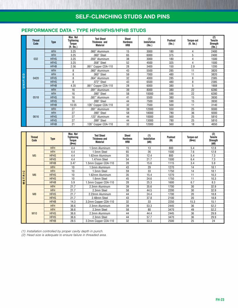
Max. Nut Test Sheet Sheet (1) (2) Thread Type Tightening Thickness and Hardness Installation Pushout Torque-out Tensile Code Torque Material HRB (lbs.) (lbs.) (ft. lbs.) Strength (ft. lbs.) (lbs.)
hfh 3.25 .060” Aluminum 15 3000 180 4 2400 hfh 3.25 .060” steel 65 6000 375 5 2400 032 hfhs 3.25 .050” Aluminum 38 3000 180 4 1500 hfhs 3.25 .058” steel 52 4500 325 4 1500 hfhb 2.56 .061” Copper CDA-110 28 3400 150 2.9 1200 hfh 8 .060” Aluminum 43 5500 285 11 3820 hfh 8 .060” steel 59 7000 480 11 3820 0420 hfhs 8 .064” Aluminum 32 4000 285 8 2385 hfhs 8 .072” steel 43 6500 480 8 2385 hfhb 4.35 .061” Copper CDA-110 28 6000 380 5 1908 hfh 16 .091” Aluminum 39 8000 380 22 6280 hfh 16 .090” steel 58 10000 590 22 6280 0518 hfhs 16 .087” Aluminum 41 5500 380 15 3930 hfhs 16 .099” steel 44 7500 590 15 3930 hfhb 10.55 .126” Copper CDA-110 32 7500 500 11 3140 hfh 27 .091” Aluminum 39 12000 550 25 9300 hfh 27 .090” steel 58 18000 780 36 9300 0616 hfhs 27 .123” Aluminum 44 10000 560 25 5810 hfhs 27 .099” steel 44 13000 780 25 5810 hfhb 21 .126” Copper CDA-110 32 12000 560 18 4650
PERFORMANCE DATA - TYPE HFH/HFHS/HFHB STUDS
Max. Nut Test Sheet Sheet (1) (2) Thread Type Tightening Thickness and Hardness Installation Pushout Torque-out Tensile Code Torque Material HRB (kN) (N) (N•m) Strength (N•m) (kN)
hfh 4.4 1.5mm Aluminum 15 13 800 5.4 12.8 hfh 4.4 1.5mm steel 65 26 1500 7.6 12.8 M5 hfhs 4.4 1.62mm Aluminum 35 12.4 800 5.4 7.3 hfhs 4.4 1.47mm steel 54 21.7 1500 6.4 7.3 hfhb 3.47 1.5mm Copper CDA-110 28 15.6 1115 3.4 5.9 hfh 10 1.5mm Aluminum 43 29 1270 14 18.1 hfh 10 1.5mm steel 59 33 1750 14 18.1 M6 hfhs 10 1.62mm Aluminum 35 15.4 1270 11 10.3 hfhs 10 1.6mm steel 45 24.6 1750 11 10.3 hfhb 5.9 1.5mm Copper CDA-110 28 25.3 1600 6.7 8.3 hfh 21.7 2.3mm Aluminum 39 35.6 1700 30 32.9 hfh 21.7 2.3mm steel 58 44.5 2200 30 32.9 M8 hfhs 21.7 2.23mm Aluminum 44 24.4 1700 20 18.8 hfhs 21.7 2.48mm steel 43 37.8 2100 20 18.8 hfhb 14.3 3.2mm Copper CDA-110 32 33 2250 15.3 15.1 hfh 36.6 2.3mm Aluminum 39 53.3 2445 36 52.2 hfh 36.6 2.3mm steel 58 80 3470 49 52.2 M10 hfhs 36.6 2.3mm Aluminum 44 44.4 2445 36 29.9 hfhs 36.6 2.3mm steel 44 57.7 3470 36 29.9 hfhb 28.5 3.2mm Copper CDA-110 32 53.3 2500 25 24
(1) Installation controlled by proper cavity depth in punch.(2) Head size is adequate to ensure failure in threaded area.
FH-24
SELF-CLINCHING STUDS AND PINSU
NIF
IED
ME
TR
IC
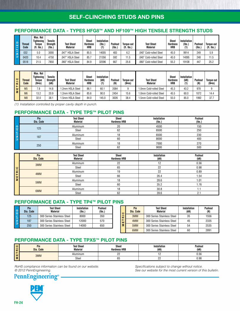
PERFORMANCE DATA - TYPE TPS™ PILOT PINS Pin Test Sheet Sheet Installation Pushout Dia. Code Material Hardness HRB (lbs.) (lbs.)
125
Aluminum 20 4500 150 steel 62 6500 250
187
Aluminum 18 6500 230 steel 60 8000 400
250
Aluminum 18 7000 270 steel 62 9000 500
Pin Test Sheet Sheet Installation Pushout Dia. Code Material Hardness HRB (kN) (kN)
3MM Aluminum 22 12 0.56
steel 65 22 0.98
4MM Aluminum 19 22 0.89
steel 66 26.4 1.54
5MM Aluminum 18 28.6 1.01
steel 60 35.2 1.76
6MM Aluminum 18 30.8 1.1
steel 62 39.6 2.1
ME
TR
IC
PERFORMANCE DATA - TYPE TPXS™ PILOT PINS Pin Test Sheet Sheet Installation Pushout Dia. Code Material Hardness HRB (kN) (kN)
3MM Aluminum 22 12 0.56
steel 65 22 0.98
ME
TR
IC
Pin Test Sheet Installation Pushout Dia. Code Material (kN) (N)
3MM 300 series stainless steel 35 1556
4MM 300 series stainless steel 45 2335
5MM 300 series stainless steel 54 2535
6MM 300 series stainless steel 60 2891
UN
IFIE
D
Pin Test Sheet Installation Pushout Dia. Code Material (lbs.) (lbs.)
125 300 series stainless steel 8000 350
187 300 series stainless steel 12000 570
250 300 series stainless steel 14000 650
PERFORMANCE DATA - TYPE TP4™ PILOT PINS
PERFORMANCE DATA - TYPES HFG8™ AND HF109™ HIGH TENSILE STRENGTH STUDS
UN
IFIE
D
Max. Nut Tightening Tensile Sheet Installation Sheet Installation Thread Torque Strength Test Sheet Hardness (lbs.) Pushout Torque-out Test Sheet Hardness (lbs.) Pushout Torque-out Code (ft. lbs.) (lbs.) Material HRB (1) (lbs.) (ft. lbs.) Material HRB (1) (lbs.) (ft. lbs.)
032 5.0 3000 .047” hsLA steel 85.5 14005 483 6.2 .040” Cold-rolled steel 45.0 9914 249 5.9
0420 10.4 4750 .047” hsLA steel 85.7 21356 592 11.5 .040” Cold-rolled steel 45.0 14095 248 11.5
0518 21.5 7850 .060” hsLA steel 84.9 32596 667 25.6 .060” Cold-rolled steel 55.2 19108 447 25.2
ME
TR
IC
Max. Nut Tightening Tensile Sheet Installation Sheet Installation Thread Torque Strength Test Sheet Hardness (kN) Pushout Torque-out Test Sheet Hardness (kN) Pushout Torque-out Code (N•m) (kN) Material HRB (1) (N) (N•m) Material HRB (1) (N) (N•m)
M5 7.8 14.8 1.2mm hsLA steel 86.1 60.1 2084 9 1.0mm Cold-rolled steel 45.3 43.2 978 9
M6 13.2 20.9 1.2mm hsLA steel 85.6 90.0 2454 15.6 1.0mm Cold-rolled steel 45.5 60.0 1072 14.4
M8 32.0 38.1 1.5mm hsLA steel 84.0 145.0 3026 38.4 1.5mm Cold-rolled steel 55.0 85.0 1992 37.7
(1) Installation controlled by proper cavity depth in punch.
Specifications subject to change without notice. See our website for the most current version of this bulletin.
RoHS compliance information can be found on our website.© 2012 PennEngineering.