self defence and alert system for individuals - ijedr · self defence and alert system for...
TRANSCRIPT
© 2014 IJEDR | Volume 2, Issue 1 | ISSN: 2321-9939
IJEDR1401042 International Journal of Engineering Development and Research ( www.ijedr.org) 237
Self Defence and Alert System for Individuals
D. Suvarna Kumara
M.Tech Scholar
Hyderabad
India
D. Narender Singh
Asst. Professor
Hyderabad,
India
Abstract--Self defence and self protection are an important priority for women or Men. Some women find themselves at a greater risk
for becoming the victim of either serious assault or murder, but it is more about a feeling of dominance from one person over another.
Even though women are targeted, the overall point is that their needless victimization could have been prevented. Even women who
perform the necessary steps to stay alive—such as getting a restraining order, hiding, and filing criminal charges—still end up dead.
Therefore, avoiding any violent attack is better that attempting to survive one.
Self defence and alert system for individuals is avoid these crimes in alone or being in badly lit areas also. By using this system
Whenever there is a threat to the person then he/she has to press the switch of the equipment to alert all the modules i.e. voice alert, self
defence device, GPS, GPRS, a web camera is attached to the equipment and capturers the image and sent MMS to the particular
registered mobile number and using further evidence about the crime, a voice alert helps whenever a person switch ON the equipment
to alert the surrounding persons where there is a crime, Global Positioning Service gives the location of wherever there is a threat as
Latitude and Longitude and sent SMS of Latitude and Latitude to particular registered number using GPRS technology .General
packet Radio Service sent MMS of the captured image to particular registered number using GPRS technology or using further
evidence about the crime and Self Defence Device is used for whenever there is a threat to the person then he/she has to press the switch
of the equipment then the spray bottle which contains chloroform automatically spreads over the area where the crime takes place, and
the criminal gets unconscious.
Index Terms - ARM 9 Processor, Switch, Web camera, GPRS,GPS,Self Defence Device (Spray Bottle) and LINUX based.
I. INTRODUCTION
The present life of every human has become a day –night trusty life. In clear there I no hundred percent protection without any
difference between a men and women, even the government has taken and been taking many precautions and working with
enough courage up to the mark and there are many self defence classes. But even after all the primary requirements are fulfilled
they may take time to put our self protection.
The self defence device and alert system can protect us and instantly when the cause has taken place. This device consists of
ARM9 board which is ported with Linux in it. And this ARM 9 board with LINUX will be connected to the different modules are
voice alert, web camera, GPRS, GPS, Self defence device (spray bottle).A web camera captures image and sent MMS to the
particular registered number and using for further evidence also. A voice alert helps surrounding persons where there is a crime;
GPS gives the location of particular location as Longitude and longitude and sent the SMS to the registered number.
In this project we are going to use the ARM9 based microcontroller, which is the current dominant microcontroller in mobile
based products and soft ware development tool a Keil, flash magic for loading the hex file to the Microcontroller.
II. SYSTEM REQUIREMENTS
Switch: Whenever there is a threat to the person then he/she has to press the switch of the equipment to alert all the modules i.e.
voice alert, self defence device, GPS, GPRS.
Web Camera: A web camera is attached to the equipment and capturers the image and sent MMS to the particular registered
mobile number and using further evidence about the crime.
For the respective input signals given to the specific hardware will alert the mobile of the other person, giving the location where
the crime happening, capturing the situation and sent to the other‘s mobile or using further evidence about the crime.
Voice alert: whenever a person switches ON the equipment to alert the surrounding persons where there is a crime. This kernel
supports the audio capabilities of the Mini2440 via a standard ALSA (Advanced Linux Sound Architecture) device. So, most of
the available tools to play or record sounds should work out of the box.
To control the audio mixer run the tool alsamixer, to play a simple sound file a play can be used and for MP3 files, textttmadplay
is the correct tool.
GPS: Global Positioning Service gives the location of wherever there is a threat as Latitude and Longitude and sent SMS of
Latitude and Latitude to particular registered number using GPRS technology
GPRS: General packet Radio Service sent MMS of the captured image to particular registered number using GPRS technology or
using further evidence about the crime.
Self Defence Device: Whenever there is a threat to the person then he/she has to press the switch of the equipment then the spray
bottle which contains chloroform automatically spreads over the area where the crime takes place, and the criminal gets
unconscious.

Self Defence and Alert System for Individual
IJEDR1401042 International Journal of Engineering Development and Research ( www.ijedr.org) 238
III. SYSTEM ARCHITECTURE
Fig.1 Proposed system Architecture
IV. SYSTEM HARDWARE
The basic idea behind this project is, it implies that a person is at a greater risk for becoming the victim of either serious assault or
murder to avoid these crimes in alone or being in badly lit areas also. It gives the information to the other persons using
a) VOICE ALERT: Whenever a person switches ON the equipment to alert the surrounding persons where there is a crime.
This kernel supports the audio capabilities of the Mini2440 via a standard ALSA (Advanced Linux Sound Architecture)
device. So, most of the available tools to play or record sounds should work out of the box. To control the audio mixer run
the tool alsamixer, to play a simple sound file a play can be used and for MP3 files, textttmadplay is the correct tool.
b) UVC (Universal video class) DRIVER CAMERA : A UVC driver camera is a video camera that feeds its image in real
time to a computer or computer network. Unlike an IP camera (which uses a direct connection using Ethernet or Wi-Fi), a
webcam is generally connected by a USB cable, FireWire cable, or similar cable. Their most popular use is the establishment
of video links, permitting computers to act as videophones or videoconference stations. The common use as a video
camera for the World Wide Web gave the webcam its name. Other popular uses include security surveillance, computer
vision, video broadcasting, and for recording social videos. Webcams are known for their low manufacturing cost and
flexibility, making them the lowest cost form of video telephony. They have also become a source of security and privacy
issues, as some built-in webcams can be remotely activated via spyware.
Technology
Webcams typically include a lens, an image sensor, support electronics, and may also include a microphone for sound.
Various lenses are available, the most common in consumer-grade webcams being a plastic lens that can be screwed in and
out to focus the camera. Fixed focus lenses, which have no provision for adjustment, are also available. As a camera
system's depth of field is greater for small image formats and is greater for lenses with a large f-number (small aperture), the
systems used in webcams have a sufficiently large depth of field that the use of a fixed focus lens does not impact image
sharpness to a great extent.
Image sensors can be CMOS or CCD, the former being dominant for low-cost cameras, but CCD cameras do not necessarily
outperform CMOS-based cameras in the low cost price range. Most consumer webcams are capable of
providing VGA resolution video at a frame rate of 30 frames per second. Many newer devices can produce video in multi-
mega pixel resolutions, and a few can run at high frame rates such as the PlayStation Eye, which can produce 320×240 video
at 120 frames per second.
Support electronics read the image from the sensor and transmit it to the host computer. The camera pictured to the right, for
example, uses a Sonix SN9C101 to transmit its image over USB. Typically, each frame is transmitted uncompressed
in RGB or YUV or compressed as JPEG. Some cameras, such as mobile phone cameras, use a CMOS sensor with supporting
electronics "on die", i.e. the sensor and the support electronics are built on a single silicon chip to save space and
manufacturing costs. Most webcams feature built-in microphones to make video calling and videoconferencing more
convenient.
The USB video device class (UVC) specification allows for interconnectivity of webcams to computers without the need for
proprietary device drivers. Microsoft Windows XP SP2,Linux and Mac OS X (since October 2005) have UVC support built
in and do not require extra device drivers, although they are often installed to add additional features.
Uses
Commerce
Webcams have been increasingly used for Augmented Reality experiences online. One such function has the webcam act as a
'magic mirror' to allow an online shopper to view a virtual item on themselves. The Webcam Social Shopper is one example
of software that utilizes the webcam in this manner
Video calling and videoconferencing
S3C2440
(ARM9)
SWITCH
SELF DEFENCE
DEVICE
WEBCAM
GPS
GPRS
MODEM
MOBILE
VOICE ALARM

Self Defence and Alert System for Individual
IJEDR1401042 International Journal of Engineering Development and Research ( www.ijedr.org) 239
As webcam capabilities have been added to instant messaging, text chat services such as AOL Instant Messenger,
and VoIP services such as Skype, one-to-one live video communication over the Internet has now reached millions of
mainstream PC users worldwide. Improved video quality has helped webcams encroach on traditional video conferencing
systems. New features such as automatic lighting controls, real-time enhancements (retouching, wrinkle smoothing and
vertical stretch), automatic face tracking and autofocus, assist users by providing substantial ease-of-use, further increasing
the popularity of webcams.
Webcam features and performance can vary by program, computer operating system, and also by the computer's processor
capabilities. Video calling support has also been added to several popular instant messaging programs.
Video security
Webcams are also used as security cameras. Software is available to allow PC-connected cameras to watch for movement
and sound, recording both when they are detected. These recordings can then be saved to the computer, e-mailed, or uploaded
to the Internet. In one well-publicized case, computer e-mailed images of the burglar during the theft of the computer,
enabling the owner to give police a clear picture of the burglar's face even after the computer had been stolen.
Recently webcam privacy software has been introduced by such companies such as Stop Being Watched or Webcamlock.
The software exposes access to a webcam and prompts the user to allow or deny access by showing what program is trying to
access the webcam. Allowing the user to accept a trusted program the user recognizes or terminate the attempt immediately.
Other companies on the market manufacture and sell sliding lens covers that allow users to retrofit the computer and close
access to the camera lens.
c) GPRS: General Packet Radio Service
GPRS is a packet oriented mobile data service on the 2G and 3G cellular communication system's global system for mobile
communications (GSM). GPRS was originally standardized by European Telecommunications Standards Institute (ETSI) in
response to the earlier CDPD and i-mode packet-switched cellular technologies. It is now maintained by the 3rd Generation
Partnership Project (3GPP).
GPRS usage is typically charged based on volume of data. This contrasts with circuit switching data, which is typically billed
per minute of connection time, regardless of whether or not the user transfers data during that period.
GPRS data is typically supplied either as part of a bundle (e.g., 5 GB per month for a fixed fee) or on a pay-as-you-use basis.
Usage above the bundle cap is either charged per megabyte or disallowed. The pay-as-you-use charging is typically per
megabyte of traffic.
GPRS is a best-effort service, implying variable throughput and latency that depend on the number of other users sharing the
service concurrently, as opposed to circuit switching, where a certain quality of service (QoS) is guaranteed during the
connection. In 2G systems, GPRS provides data rates of 56–114 kbit/second. 2G cellular technology combined with GPRS is
sometimes described as 2.5G, that is, a technology between the second (2G) and third (3G) generations of mobile telephony.
It provides moderate-speed data transfer, by using unused time division multiple access (TDMA) channels in, for example,
the GSM system. GPRS is integrated into GSM Release 97 and newer releases.
The GPRS core network allows 2G, 3G and WCDMA mobile networks to transmit IP packets to external networks such as
the Internet. The GPRS system is an integrated part of the GSM network switching subsystem.
Services offered
GPRS extends the GSM Packet circuit switched data capabilities and makes the following services possible:
SMS messaging and broadcasting
"Always on" internet access
Multimedia messaging service (MMS)
Push to talk over cellular (PoC)
Instant messaging and presence—wireless village
Internet applications for smart devices through wireless application protocol (WAP)
Point-to-point (P2P) service: inter-networking with the Internet (IP)
Point-to-Multipoint (P2M) service: point-to-multipoint multicast and point-to-multipoint group calls
If SMS over GPRS is used, an SMS transmission speed of about 30 SMS messages per minute may be achieved. This is
much faster than using the ordinary SMS over GSM, whose SMS transmission speed is about 6 to 10 SMS messages per
minute.
Protocols supported
GPRS supports the following protocols:
Internet protocol (IP). In practice, built-in mobile browsers use IPv4 since IPv6 was not yet popular.
Point-to-point protocol (PPP). In this mode PPP is often not supported by the mobile phone operator but if the
mobile is used as a modem to the connected computer, PPP is used to tunnel IP to the phone. This allows an IP
address to be assigned dynamically to the mobile equipment.
X.25 connections. This is typically used for applications like wireless payment terminals, although it has been
removed from the standard. X.25 can still be supported over PPP, or even over IP, but doing this requires either a
network based router to perform encapsulation or intelligence built in to the end-device/terminal; e.g., user
equipment (UE).
When TCP/IP is used, each phone can have one or more IP addresses allocated. GPRS will store and forward the IP packets
to the phone even during handover. The TCP handles any packet loss (e.g. due to a radio noise induced pause).
Hardware
Devices supporting GPRS are divided into three classes:

Self Defence and Alert System for Individual
IJEDR1401042 International Journal of Engineering Development and Research ( www.ijedr.org) 240
Class A
Can be connected to GPRS service and GSM service (voice, SMS), using both at the same time. Such devices are
known to be available today.
Class B
Can be connected to GPRS service and GSM service (voice, SMS), but using only one or the other at a given time. During
GSM service (voice call or SMS), GPRS service is suspended, and then resumed automatically after the GSM service (voice
call or SMS) has concluded. Most GPRS mobile devices are Class B.
Class C
Are connected to either GPRS service or GSM service (voice, SMS). Must be switched manually between one or the
other service.
A true Class A device may be required to transmit on two different frequencies at the same time, and thus will need two
radios. To get around this expensive requirement, a GPRS mobile may implement the dual transfer mode (DTM) feature. A
DTM-capable mobile may use simultaneous voice and packet data, with the network coordinating to ensure that it is not
required to transmit on two different frequencies at the same time. Such mobiles are considered pseudo-Class A, sometimes
referred to as "simple class A". Some networks support DTM since 2007.
Addressing
A GPRS connection is established by reference to its access point name (APN). The APN defines the services such as
wireless application protocol (WAP) access, short message service (SMS), multimedia messaging service (MMS), and for
Internet communication services such as email and World Wide Web access.
In order to set up a GPRS connection for a wireless modem, a user must specify an APN, optionally a user name and
password, and very rarely an IP address, all provided by the network operator.
d) GPS (Global Positioning service)
A GPS receiver calculates its position by precisely timing the signals sent by GPS satellites high above the Earth. Each
satellite continually transmits messages that include
the time the message was transmitted
satellite position at time of message transmission
The receiver uses the messages it receives to determine the transit time of each message and computes the distance to each
satellite using the speed of light. Each of these distances and satellites' locations defines a sphere. The receiver is on the
surface of each of these spheres when the distances and the satellites' locations are correct. These distances and satellites'
locations are used to compute the location of the receiver using the navigation equations. This location is then displayed,
perhaps with a moving map display or latitude and longitude; elevation or altitude information may be included, based on
height above the geoid (e.g. EGM96).
GPS receivers receive almanac data from the satellite and also calculate their position by calculating its distance from then
visible satellites and then by using triangulation method to calculate its position.
After the data has been received and position has been calculated, the data is configured according to standards set up
by NMEA (National Marine Electronics Association) and is serially transmitted at a baud rate of 4800 bps.
The National Marine Electronics Association (NMEA) has developed standards that describe the interface between various
marine electronic equipments. The standards allow marine electronics to send information to computers and to other marine
equipments.
GPS receivers also work on these NMEA Standards. Most of the computer programs and devices which provide position
and other related information expect the data to be in NMEA format.
The data given by the GPS receiver includes many information like position (latitude and longitude), altitude, speed, time
etc. In its standards, NMEA has specified to send a series of data in a sentence. A particular sentence is totally self-reliant
and is independent from other sentences. There are standard sentences for particular type of data and for various categories of
devices. NMEA has also provided the functionality for individual companies to write their own sentences.
All standard devices have a two letter prefix that defines the device for which it is being used, for GPS receivers the prefix
is GP. The two letter prefix is then followed by three letters which represent the content of the sentence. The proprietor
sentences allowed by the NMEA always start with P and are followed by a three letter sequence identifying manufacturer
code and additional characters to define sentence type. For example a Garmin sentence would start with PGRM and Sony
would begin with PSNY.
Every sentence begins with a ‗$‘ sign, has about 80 characters and ends up with a carriage return/line feed sequence.
Sentences are mostly framed in single lines (may run over to multiple lines sometimes) and the data items in each sentence
are separated by commas.
The data received is just ASCII text and varies in precision. A sentence ends with checksum which consists of a ‗*‘ and two
hexadecimal digits. The checksum digits represent an 8 bit exclusive OR of all the characters between, but not including,

Self Defence and Alert System for Individual
IJEDR1401042 International Journal of Engineering Development and Research ( www.ijedr.org) 241
the $ and *.
GPS units are made compatible to NMEA standards and are also compatible with serial ports using RS232 protocols. The
serial configuration of a GPS receiver is summed as follows:
BAUD RATE DATA bits STOP bits PARITY HANDSHAKE
4800 bps
8 1 None None
$GPGGA - Global Positioning System Fix Data
$GPGGA,132453.970,2651.0138,N,07547.7054,E,1,03,7.1,42.5,M,-42.5,M,,0000*45
where:
GGA
132453.970
2651.0138, N
07547.7054, E
1
03
7.1
42.5, M
46.9, M
Empty field
Empty field
*45
Global Positioning System Fix Data
Fix taken at 13:24:53970 UTC
Latitude 26 deg 51.0138' N
Longitude 07 deg 54.7054' E
Fix quality:
0 = invalid
1 = GPS fix (SPS)
2 = DGPS fix
3 = PPS fix
4 = Real Time Kinematic
5 = Float RTK
6 = Estimated (dead reckoning)
7 = Manual input mode
8 = Simulation mode
Number of satellites being tracked
Horizontal dilution of position
Altitude, Meters, above mean sea level
Height of geoid (mean sea level) above WGS84 Ellipsoid
Time in seconds since last DGPS update
DGPS station ID number
The checksum data, always begins with *
$GPGSV - (Satellites in view)
GPGSV sentence shows data about the satellites that are in view of the receiver. Each GPGSV sentence can show data for
maximum of four satellites, so three sentences are required represent full data. All 3 sentences need not appear in sequence as
each sentence can be identified easily.
A GPGSV sentence can show more number of satellites than GPGGA sentence as it also shows the satellites which are not in
solution. The SNR (Signal to Noise Ratio) can be used as raw signal strength and lies between 0 and 99. Zero being the signal
strength for the satellite being viewed but not tracked.
$GPGSV,3,1,12,18,57,291,40,21,56,346,45,26,23,043,46,29,57,174,25*71
$GPGSV,3,2,12,22,28,259,16,27,13,107,,09,11,130,,16,09,288,25*79
$GPGSV,3,3,12,30,08,210,33,06,08,320,22,25,02,188,26,14,01,203,21*7B
where:
GSV
3
1
12
18
57
291
40
*75
Satellites in view
Number of sentences for full data
Sentence 1
Number of satellites in view
Satellite PRN(Pseudorandom Noise) number
Elevation, degrees
Azimuth, degrees
SNR (Signal to noise Ratio) - higher is better
For up to 4 satellites per sentence
The checksum data, always begins with *

Self Defence and Alert System for Individual
IJEDR1401042 International Journal of Engineering Development and Research ( www.ijedr.org) 242
99999
3) $GPRMC - Recommended minimum specific GPS/Transit data
$GPRMC,132455.970,A,2651.0145,N,07547.7051,E,0.50,342.76,301010,,,A*64
where:
RMC
132455.970
A
2651.0145, N
07547.7051, E
0.50
342.76
301010
Empty field (xxx.x, y)
*64
Recommended Minimum sentence C
Fix taken at 13:24:55.970 UTC
Status A=Active or V=Void.
Latitude 26 deg 51.0145' N
Longitude 075 deg 47.7051' E
Speed over the ground in knots
Track angle in degrees True
Date : 30th of October 2010
Magnetic Variation
The checksum data, always begins with *
4) $GPVTG -
$GPVTG,054.7,T,034.4,M,005.5,N,010.2,K*48
where:
VTG
054.7, T
034.4, M
005.5, N
010.2, K
*48
Track made good and ground speed
True track made good (degrees)
Magnetic track made good
Ground speed, knots
Ground speed, Kilometres per hour
The checksum data, always begins with *
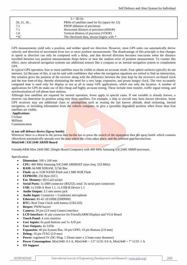
5) $GPGSA -
This sentence shows the dilution of precision (DOP) and PRN of active satellites. DOP shows the effect of satellite geometry on
the accuracy of the fix. DOP is a number and for 3D fix using four satellites a DOP of 1.0 is perfect.
$GPGSA,A,2,26,21,18,,,,,,,,,,7.1,7.1,1.0*3C
where:
GSA
A
2
Satellite status
Auto selection of 2D or 3D fix (M = manual)
2D fix
where:
1 = no fix
2 = 2D fix
1 Total number of messages of this type in this cycle
2 Message number
3 Total number of SVs in view
4 SV PRN number
5 Elevation in degrees, 90 maximum
6 Azimuth, degrees from true north, 000 to 359
7 SNR, 00-99 dB (null when SV is visible but not tracked)
8-11 Information about second SV, same as field 4-7
12-15 Information about third SV, same as field 4-7
16-19 Information about fourth SV, same as field 4-7
1 Track made good
2 Fixed text 'T' indicates that track made good is relative to true north
3 Magnetic track made good
4 Fixed text 'N' indicates degrees magnetic
5 Speed over ground in knots
6 Fixed text 'N' indicates that speed over ground in knots
7 Speed over ground in kilometres/hour
8 Fixed text 'K' indicates that speed over ground is in kilometres/hour
9 Checksum
Self Defence and Alert System for Individual
IJEDR1401042 International Journal of Engineering Development and Research ( www.ijedr.org) 243
26, 21, 18...
7.1
7.1
1.0
*3C
3 = 3D fix
PRNs of satellites used for fix (space for 12)
PDOP (dilution of precision)
Horizontal dilution of precision (HDOP)
Vertical dilution of precision (VDOP)
The checksum data, always begins with *
GPS measurements yield only a position, and neither speed nor direction. However, most GPS units can automatically derive
velocity and direction of movement from two or more position measurements. The disadvantage of this principle is that changes
in speed or direction can only be computed with a delay, and that derived direction becomes inaccurate when the distance
travelled between two position measurements drops below or near the random error of position measurement. To counter this
effect, more advanced navigation systems use additional sensors like a compass or an inertial navigation system to complement
GPS.
In typical GPS operation, four or more satellites must be visible to obtain an accurate result. Four sphere surfaces typically do not
intersect. [a] Because of this, it can be said with confidence that when the navigation equations are solved to find an intersection,
this solution gives the position of the receiver along with the difference between the time kept by the receiver's on-board clock
and the true time-of-day, thereby eliminating the need for a very large, expensive, and power hungry clock. The very accurately
computed time is used only for display or not at all in many GPS applications, which use only the location. A number of
applications for GPS do make use of this cheap and highly accurate timing. These include time transfer, traffic signal timing, and
synchronization of cell phone base stations.
Although four satellites are required for normal operation, fewer apply in special cases. If one variable is already known, a
receiver can determine its position using only three satellites. For example, a ship or aircraft may have known elevation. Some
GPS receivers may use additional clues or assumptions such as reusing the last known altitude, dead reckoning, inertial
navigation, or including information from the vehicle computer, to give a (possibly degraded) position when fewer than four
satellites are visible.
Applications:
Civilian
Millitary
Communication
e) one self defence device (Spray bottle) Whenever there is a threat to the person then he/she has to press the switch of the equipment then the spray bottle which contains
chloroform automatically spreads over the area where the crime takes place, and the criminal gets unconscious.
Mini2440 | S3C2440 ARM9 Board
FriendlyARM Mini 2440 SBC (Single-Board Computer) with 400 MHz Samsung S3C2440 ARM9 processor.
Specification
Dimension: 100 x 100 mm
CPU: 400 MHz Samsung S3C2440 ARM926T (max freq. 533 MHz)
RAM: 64 MB SDRAM, 32 bit Bus
Flash: up to 1GB NAND Flash and 2 MB NOR Flash
EEPROM: 256 Byte (I2C)
Ext. Memory: SD-Card socket
Serial Ports: 1x DB9 connector (RS232), total: 3x serial port connectors
USB: 1x USB-A Host 1.1, 1x USB-B Device 1.1
Audio Output: 3.5 mm stereo jack
Audio Input: Connector + Condenser microphone
Ethernet: RJ-45 10/100M (DM9000)
RTC: Real Time Clock with battery (CR1220)
Beeper: PWM buzzer
Camera: 20 pin (2.0 mm) Camera interface
LCD Interface: 41 pin connector for FriendlyARM Displays and VGA Board
Touch Panel: 4 wire resistive
User Inputs: 6x push buttons and 1x A/D pot
User Outputs: 4x LEDs
Expansion: 40 pin System Bus, 34 pin GPIO, 10 pin Buttons (2.0 mm)
Debug: 10 pin JTAG (2.0 mm)
Power: regulated 5V (DC-Plug: 1.35mm inner x 3.5mm outer diameter)
Power Consumption: Mini2440: 0.3 A, Mini2440 + 3.5" LCD: 0.6 A, Mini2440 + 7" LCD: 1 A
OS Support

Self Defence and Alert System for Individual
IJEDR1401042 International Journal of Engineering Development and Research ( www.ijedr.org) 244
o Windows CE 5 and 6
o Linux
o Android
S3C2440A MICROCONTROLLER:
SAMSUNG's S3C2440A 16/32-bit RISC microprocessor. SAMSUNG‘s S3C2440A is designed to provide hand-held devices
and general applications with low-power, and high-performance microcontroller solution in small die size. To reduce total system
cost, the S3C2440A includes the following components.
The S3C2440A is developed with ARM920T core, 0.13um CMOS standard cells and a memory complier. Its low power, simple,
elegant and fully static design is particularly suitable for cost- and power-sensitive applications. It adopts a new bus architecture
known as Advanced Micro controller Bus Architecture (AMBA). The S3C2440A offers outstanding features with its CPU core, a
16/32-bit ARM920T RISC processor designed by Advanced RISC Machines, Ltd. The ARM920T implements MMU, AMBA
BUS, and Harvard cache architecture with separate 16KB instruction and 16KB data caches, each with an 8-word line length. By
providing a complete set of common system peripherals, the S3C2440A minimizes overall system costs and eliminates the need
to configure additional components. The integrated on-chip functions that are described in this document include:
Around 1.2V internal, 1.8V/2.5V/3.3V memory, 3.3V external I/O microprocessor with 16KB I-Cache/16KB D-
Cache/MMU
External memory controller (SDRAM Control and Chip Select logic)
LCD controller (up to 4K color STN and 256K color TFT) with LCD-dedicated DMA
4-ch DMA controllers with external request pins
3-ch UARTs (IrDA1.0, 64-Byte Tx FIFO, and 64-Byte Rx FIFO)
2-ch SPI
IIC bus interface (multi-master support)
IIS Audio CODEC interface
AC‘97 CODEC interface
SD Host interface version 1.0 & MMC Protocol version 2.11 compatible
2-ch USB Host controller / 1-ch USB Device controller (ver 1.1)
4-ch PWM timers / 1-ch Internal timer / Watch Dog Timer
8-ch 10-bit ADC and Touch screen interface
RTC with calendar function
Camera interface (Max. 4096 x 4096 pixels input support. 2048 x 2048 pixel input support for scaling)
130 General Purpose I/O ports / 24-ch external interrupt source
Power control: Normal, Slow, Idle and Sleep mode
On-chip clock generator with PLL
FEATURES:
Architecture:
Integrated system for hand-held devices and General embedded applications.
16/32-Bit RISC architecture and powerful
Instruction set with ARM920T CPU core.
Enhanced ARM architecture MMU to support
WinCE, EPOC 32 and Linux.
Instruction cache, data cache, write buffer and Physical address TAG RAM to reduce the effect of main memory
bandwidth and latency on Performance.
ARM920T CPU core supports the ARM debug Architecture.
Internal Advanced Microcontroller Bus Architecture (AMBA) (AMBA2.0, AHB/APB).
System Manager
Little/Big Endean support.
Support Fast bus mode and Asynchronous bus mode.
Address space: 128M bytes for each bank (total 1G bytes).
Supports programmable 8/16/32-bit data bus width for each bank.
Fixed bank start address from bank 0 to bank 6.
Programmable bank start address and bank size for bank 7.
Eight memory banks: Six memory banks for ROM, SRAM, and others.
Two memory banks for ROM/SRAM/Synchronous DRAM.
Complete Programmable access cycles for all memory banks.
Supports external wait signals to expand the bus cycle.

Self Defence and Alert System for Individual
IJEDR1401042 International Journal of Engineering Development and Research ( www.ijedr.org) 245
Supports self-refresh mode in SDRAM for power down.
Supports various types of ROM for booting (NOR/NAND Flash, EEPROM, and others).
NAND Flash Boot Loader
Supports booting from NAND flash memory.
4KB internal buffer for booting.
Supports storage memory for NAND flash memory after booting.
Supports Advanced NAND flash
Cache Memory
64-way set-associative cache with I-Cache (16KB) and D-Cache (16KB).
8words length per line with one valid bit and two dirty bits per line.
Pseudo random or round robin replacement algorithm.
Write-through or write-back cache operation to update the main memory.
The write buffer can hold 16 words of data and four addresses.
Clock & Power Manager
On-chip MPLL and UPLL: UPLL generates the clock to operate USB
Host/Device. MPLL generates the clock to operate MCU at maximum 400MHz @ 1.3V.
Clock can be fed selectively to each function block by software.
Power mode: Normal, Slow, Idle, and Sleep mode
o Normal mode: Normal operating mode
o Slow mode: Low frequency clock without PLL
o Idle mode: The clock for only CPU is stopped.
o Sleep mode: The Core power including all peripherals is shut down.
Woken up by EINT[15:0] or RTC alarm interrupt from Sleep mode
Interrupt Controller
60 Interrupt sources (One Watch dog timer, 5 timers, 9 UARTs, 24 external interrupts, 4 DMA, 2 RTC, 2 ADC, 1 IIC, 2
SPI, 1 SDI, 2 USB, 1 LCD, 1 Battery Fault, 1 NAND and 2 Camera), 1 AC97
Level/Edge mode on external interrupt source
Programmable polarity of edge and level
Supports Fast Interrupt request (FIQ) for very urgent interrupt request
Timer with Pulse Width Modulation (PWM)
4-ch 16-bit Timer with PWM / 1-ch 16-bit internal timer with DMA-based or interrupt-based operation
Programmable duty cycle, frequency, and polarity
Dead-zone generation
Supports external clock sources
RTC (Real Time Clock)
Full clock feature: millisecond, second, minute, hour, date, day, month, and year
32.768 KHz operation
Alarm interrupt
Time tick interrupt
General Purpose Input/Output Ports
24 external interrupt ports
130 Multiplexed input/output ports
DMA Controller
4-ch DMA controller
Supports memory to memory, IO to memory, memory to IO, and IO to IO transfers
Burst transfer mode to enhance the transfer rate
LCD Controller STN LCD Displays Feature
Supports 3 types of STN LCD panels: 4-bit dual scan, 4-bit single scan, 8-bit single scan display type
Supports monochrome mode, 4 gray levels, 16 gray levels, 256 colors and 4096 colors for STN LCD
Supports multiple screen size
o Typical actual screen size: 640x480, 320x240, 160x160, and others.
o Maximum frame buffer size is 4 Mbytes.
o Maximum virtual screen size in 256 color
o mode: 4096x1024, 2048x2048, 1024x4096 and others
TFT(Thin Film Transistor) Color Displays Feature
Supports 1, 2, 4 or 8 BPP (bit-per-pixel) palette color displays for color TFT
Supports 16, 24 BPP non-palette true-color displays for color TFT
Supports maximum 16M color TFT at 24 BPP mode
LPC3600 Timing controller embedded for LTS350Q1-PD1/2(SAMSUNG 3.5‖ Portrait / 256Kcolor/Reflective a-Si TFT
LCD)

Self Defence and Alert System for Individual
IJEDR1401042 International Journal of Engineering Development and Research ( www.ijedr.org) 246
LCC3600 Timing controller embedded for LTS350Q1-PE1/2(SAMSUNG 3.5‖ Portrait / 256Kcolor/Transflective a-Si
TFT LCD)
Supports multiple screen size
o Typical actual screen size: 640x480, 320x240, 160x160, and others.
o Maximum frame buffer size is 4Mbytes.
o Maximum virtual screen size in 64K color
o mode: 2048x1024, and others
UART
3-channel UART with DMA-based or interrupt based operation
Supports 5-bit, 6-bit, 7-bit, or 8-bit serial data transmit/receive (Tx/Rx)
Supports external clocks for the UART operation (UEXTCLK)
Programmable baud rate
Supports IrDA 1.0
Loopback mode for testing
Each channel has internal 64-byte Tx FIFO and 64-byte Rx FIFO.
A/D Converter & Touch Screen Interface
8-ch multiplexed ADC
Max. 500KSPS and 10-bit Resolution
Internal FET for direct Touch screen interface
Watchdog Timer
16-bit Watchdog Timer
Interrupt request or system reset at time-out
IIC-Bus Interface
1-ch Multi-Master IIC-Bus
Serial, 8-bit oriented and bi-directional data transfers can be made at up to 100 Kbit/s in Standard mode or up to 400
Kbit/s in Fast mode.
IIS-Bus Interface
1-ch IIS-bus for audio interface with DMA-based operation
Serial, 8-/16-bit per channel data transfers
128 Bytes (64-Byte + 64-Byte) FIFO for Tx/Rx
Supports IIS format and MSB-justified data format
AC97 Audio-CODEC Interface
Support 16-bit samples
1-ch stereo PCM inputs/ 1-ch stereo PCM outputs 1-ch MIC input
USB Host
2-port USB Host
Complies with OHCI Rev. 1.0
Compatible with USB Specification version 1.1
USB Device
1-port USB Device
5 Endpoints for USB Device
Compatible with USB Specification version 1.1
SD Host Interface
Normal, Interrupt and DMA data transfer mode (byte, half word, word transfer)
DMA burst4 access support (only word transfer)
Compatible with SD Memory Card Protocol version 1.0
Compatible with SDIO Card Protocol version 1.0
64 Bytes FIFO for Tx/Rx
Compatible with Multimedia Card Protocol version 2.11
SPI INTERFACE
Compatible with 2-ch Serial Peripheral Interface Protocol version 2.11
2x8 bits Shift register for Tx/Rx
DMA-based or interrupt-based operation
Camera Interface
ITU-R BT 601/656 8-bit mode support
DZI (Digital Zoom In) capability
Programmable polarity of video sync signals
Max. 4096 x 4096 pixels input support (2048 x 2048 pixel input support for scaling)
Image mirror and rotation (X-axis mirror, Y-axis mirror, and 180° rotation)

Self Defence and Alert System for Individual
IJEDR1401042 International Journal of Engineering Development and Research ( www.ijedr.org) 247
Camera output format (RGB 16/24-bit and YCbCr 4:2:0/4:2:2 format)
Operating Voltage Range
Core: 1.20V for 300MHz
1.30V for 400MHz
Memory: 1.8V/ 2.5V/3.0V/3.3V
I/O: 3.3V
Operating Frequency
Fclk Up to 400MHz
Hclk Up to 136MHz
Pclk Up to 68MHz
Package
289-FBGA
Rs232
When communicating with various micro processors one needs to convert the RS232 levels down to lower levels, typically 3.3 or
5.0 Volts. Here is a cheap and simple way to do that. Serial RS-232 (V.24) communication works with voltages -15V to +15V
for high and low. On the other hand, TTL logic operates between 0V and +5V . Modern low power consumption logic operates
in the range of 0V and +3.3V or even lower.
Thus the RS-232 signal levels are far too high TTL electronics, and the negative RS-232 voltage for high can‘t be handled at all
by computer logic. To receive serial data from an RS-232 interface the voltage has to be reduced. Also the low and high voltage
level has to be inverted. This level converter uses a Max232 and five capacitors. The max232 is quite cheap (less than 5 dollars)
or if youre lucky you can get a free sample from Maxim. The MAX232 from Maxim was the first IC which in one package
contains the necessary drivers and receivers to adapt the RS-232 signal voltage levels to TTL logic. It became popular, because it
just needs one voltage (+5V or +3.3V) and generates the necessary RS-232 voltage levels.
MAX 232 PIN DIAGRAM
+---\/---+
1 -|C1+ Vcc|- 16
2 -|V+ gnd|- 15
3 -|C1- T1O|- 14
4 -|C2+ R1I|- 13
5 -|C2- R1O|- 12
6 -|V- T1I|- 11
7 -|T2O T2I|- 10
8 -|R2I R2O|- 9
+--------+
RS-232 TTL Logic
-15V … -3V +2V … +5V High
+3V …
+15V
0V …
+0.8V Low

Self Defence and Alert System for Individual
IJEDR1401042 International Journal of Engineering Development and Research ( www.ijedr.org) 248
V.SYSTEM SOFTWARE
Linux
Linux refers to the family of Unix-like computer operating systems using the Linux kernel. Linux can be installed on a wide
variety of computer hardware, ranging from mobile phones, tablet computers and video game consoles, to mainframes and
supercomputers. Linux is the leading server OS, accounting for more than 50% of installations. Desktop use of Linux has
increased in recent years, partly owing to the popular Ubuntu, Fedora, and open USE distributions and the emergence of net
books and smart phones running an embedded Linux.
The name "Linux" comes from the Linux kernel, originally written in 1991 by Linus Torvalds. The main supporting user space
system tools and libraries from the GNU Project (announced in 1983 by Richard Stallman) are the basis for the Free Software
Foundation's preferred name GNU/Linux.
The development of Linux is one of the most prominent examples of free and open source software collaboration; typically all the
underlying source code can be used, freely modified, and redistributed, both commercially and non-commercially, by anyone
under licenses such as the GNU General Public License. Typically Linux is packaged in a format known as a Linux distribution
for desktop and server use. Linux distributions include the Linux kernel and all of the supporting software required to run a
complete system, such as utilities and libraries, the X Window System, the GNOME and KDE desktop environments, and the
Apache HTTP Server. Commonly used applications with desktop Linux systems include the Mozilla Firefox web-browser, the
OpenOffice.org office application suite and the GIMP image editor.
Features of Linux:
Linux has evolved to have the following features as an outstanding operating system which is strong in security and networking.
• Multitasking: Several programs can run at the same time.
•Multiuser: Several users can logon to the same machine at the same time There is no need to have separate user licenses.
• Multiplatform: Linux runs on many different CPUs, that means it supports multiprocessor machine.
• Multithreading: Linux has native kernel support for multiple independent threads of control within a single process memory
space.
•Crash proof: Linux has memory protection between processes, so that one program can't bring the whole system down.
•Demand loads executables: Linux only reads from those parts of a program that are actually used on the disk.
•Shared copy-on-write pages among executables: This means that multiple processes can use the same memory to run in. When
one tries to write to that memory, that page (with 4KB piece of memory) is copied somewhere else. Copy-on-write has two
benefits: increasing speed and decreasing memory use.
• Virtual memory uses paging (not swapping whole processes) to disk to a separate partition or a file in the file system, or both,
with the possibility of adding more swapping areas during runtime (yes, they're still called swapping areas). A total of 16 of these
128 MB (2GB in recent kernels) swapping areas can be used at the same time, for a theoretical total of 2 GB of usable swap
space. It is simple to increase this if necessary, by changing a few lines of source code.
•Linux has a unified memory pool for user programs and disk cache, so that all free memory can be used for caching, and the
cache can be reduced when running large programs.
• Linux does core dumps for post-mortem analysis, allowing the use of a debugger on a program not only while it is running but
also after it has crashed.
• Linux is mostly compatible with POSIX, System V, and BSD at the source level.
• Through an iBCS2-compliant emulation module, Linux is mostly compatible with SCO, SVR3, and SVR4 at the binary level.
• Free and Open source code for all: All source code of Linux is available, including the whole kernel and all drivers, the
development tools and all user programs; also, all of it is freely distributable. Plenty of commercial programs are being provided
for Linux without source, but everything that has been free, including the entire base operating system, is still free.
• Linux supports pseudo terminals (pty's) and multiple virtual consoles: By several independent login sessions through the
console, you can switch between by pressing a hot-key combination (not dependent on video hardware). These are dynamically
allocated; you can use up to 64.
• Linux supports several common file systems, including minix, Xenix, and all the common system V file systems, and has an
advanced file system of its own, which offers file systems of up to 4 TB, and names up to 255 characters long.
• Linux has a transparent access to MS-DOS partitions (or OS/2 FAT partitions) via a special file system:.You don't need any
special commands to use the MS-DOS partition, it looks just like a normal Unix file system (except for funny restrictions on file
names, permissions, and so on). MS-DOS 6 compressed partitions do not work at this time without a patch (dmsdosfs). Also
VFAT (WNT, Windows 95) support and FAT-32 is available in Linux 2.0
• Linux has CD-ROM file system which reads all standard formats of CD-ROMs.
• Linux performs well with TCP/IP networking, including ftp, telnet, NFS, etc.
• Linux is user-friendly as Netware client and server
• Linux also runs as Lan Manager/Windows Native (SMB) client and server
• It integrates many networking protocols: The base protocols available in the latest development kernels include TCP, IPv4,
IPv6, AX.25, X.25, IPX, DDP (Appletalk), Netrom, and others. Stable network protocols included in the stable kernels currently
include TCP, IPv4, IPX, DDP, and AX.25.
Self Defence and Alert System for Individual
IJEDR1401042 International Journal of Engineering Development and Research ( www.ijedr.org) 249
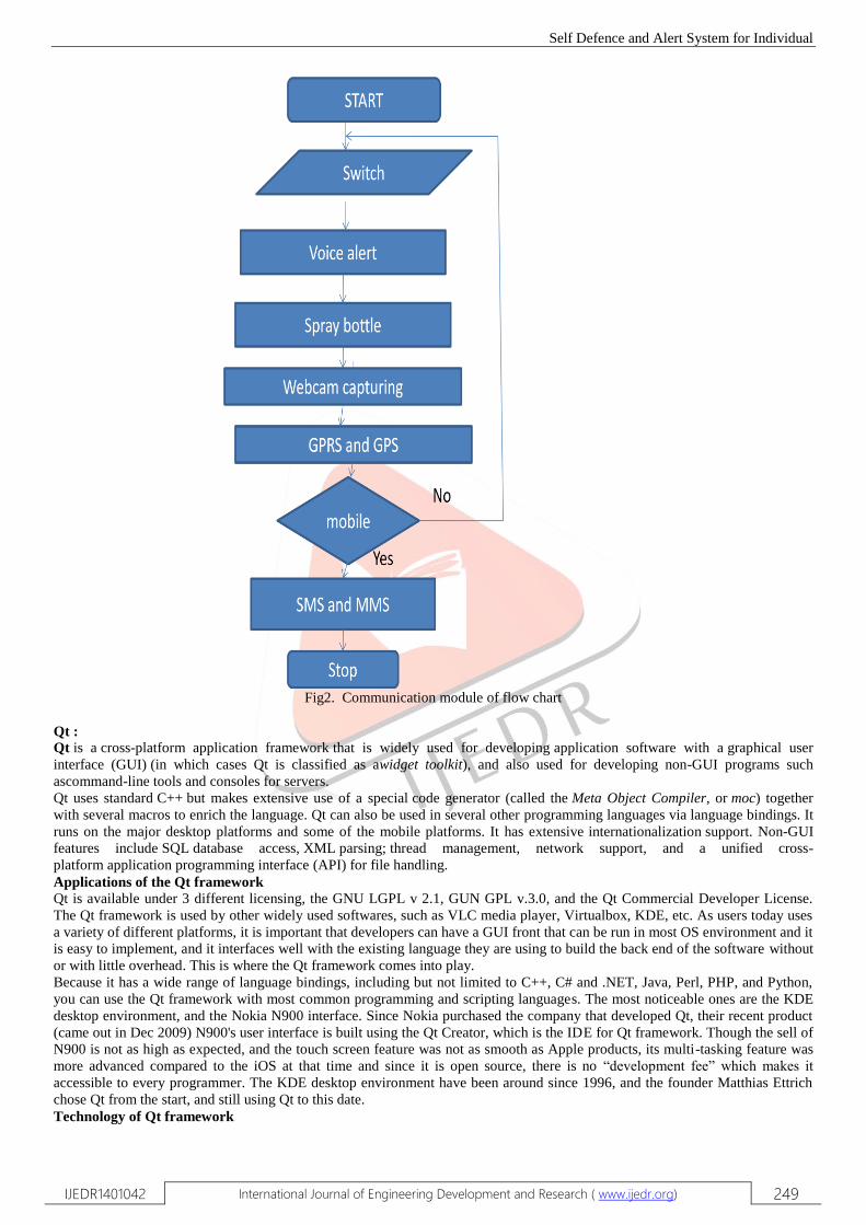
Fig2. Communication module of flow chart
Qt :
Qt is a cross-platform application framework that is widely used for developing application software with a graphical user
interface (GUI) (in which cases Qt is classified as awidget toolkit), and also used for developing non-GUI programs such
ascommand-line tools and consoles for servers.
Qt uses standard C++ but makes extensive use of a special code generator (called the Meta Object Compiler, or moc) together
with several macros to enrich the language. Qt can also be used in several other programming languages via language bindings. It
runs on the major desktop platforms and some of the mobile platforms. It has extensive internationalization support. Non-GUI
features include SQL database access, XML parsing; thread management, network support, and a unified cross-
platform application programming interface (API) for file handling.
Applications of the Qt framework
Qt is available under 3 different licensing, the GNU LGPL v 2.1, GUN GPL v.3.0, and the Qt Commercial Developer License.
The Qt framework is used by other widely used softwares, such as VLC media player, Virtualbox, KDE, etc. As users today uses
a variety of different platforms, it is important that developers can have a GUI front that can be run in most OS environment and it
is easy to implement, and it interfaces well with the existing language they are using to build the back end of the software without
or with little overhead. This is where the Qt framework comes into play.
Because it has a wide range of language bindings, including but not limited to C++, C# and .NET, Java, Perl, PHP, and Python,
you can use the Qt framework with most common programming and scripting languages. The most noticeable ones are the KDE
desktop environment, and the Nokia N900 interface. Since Nokia purchased the company that developed Qt, their recent product
(came out in Dec 2009) N900's user interface is built using the Qt Creator, which is the IDE for Qt framework. Though the sell of
N900 is not as high as expected, and the touch screen feature was not as smooth as Apple products, its multi-tasking feature was
more advanced compared to the iOS at that time and since it is open source, there is no ―development fee‖ which makes it
accessible to every programmer. The KDE desktop environment have been around since 1996, and the founder Matthias Ettrich
chose Qt from the start, and still using Qt to this date.
Technology of Qt framework

Self Defence and Alert System for Individual
IJEDR1401042 International Journal of Engineering Development and Research ( www.ijedr.org) 250
As Qt is build on C++, it inherited most of the features of C++, like Objective Oriented Concepts, Modeling etc, but it also used
special code generator, QML which is an easy to use declarative language. And with integration of the open source WebKit
rendering engine into Qt, it is easier to create web-enabled applications.
Implementation
As Qt is based on C++, it can be easily ported on to different platforms, such as Embedded Linux, Max OS X, Windows,
Linux/X11, WindowsCE, Symbian, and MeeGo. Since it is open source, it is free to use, and with a different user communities,
finding tutorials and the books you need would only take less than a day. The Qt framework for embedded Linux also comes with
its own window system, which writes directly to the Linux framebuffer, eliminating the need for the X11 windowing system. The
Qt also comes with different IDE other than its own. It has support for Eclipse, Visual Studio, Netbean. User can choose the IDE
or their choice and still use Qt for their application development.
Design
Modules
Modules for general software development
QtCore – contains core non-GUI classes, including the event loop and Qt's signal and slot mechanism, platform independent
abstractions for Unicode, threads, mapped files, shared memory, regular expressions, and user and application settings
QtGui – contains most GUI classes; including many table, tree and list classes based on model–view–controller design pattern;
also provides sophisticated 2D canvas widget able to store thousands of items including ordinary widgets
QtMultimedia – implements low-level multimedia functionality
QtNetwork – contains classes for writing UDP and TCP clients and
servers;implementing FTP and HTTP clients,supportingDNS lookups; network events are integrated with the event loop making
it very easy to develop networked applications
QtOpenGL – contains classes that enable the use of OpenGL in rendering 3D graphics
QtOpenVG – a plugin that provides support for OpenVG painting
QtScript – an ECMAScript-based scripting engine
QtScriptTools – provides added components for applications using QtScript
QtSql – contains classes that integrate with open-source and proprietary SQL databases. It includes editable data models for
database tables that can be used with GUI classes. It also includes an implementation of SQLite
QtSvg – contains classes for displaying the contents of SVG files. It supports the static features of SVG 1.2 Tiny
QtWebKit – provides a WebKit-based layout engine as well as classes to render and interact with web content
QtXml – implements SAX and DOM interfaces to Qt's XML parser
QtXmlPatterns – provides support for XPath, XQuery, XSLT and XML Schema validation
Phonon – multimedia API, provides simple multimedia control
Qt3Support – provides classes that ease porting from Qt 3 to Qt 4
Qt Declarative module is a declarative framework for building fluid user interfaces in QML
Modules for working with Qt's tools
QtDesigner
QtUiTools
QtHelp
QtTest Modules for Unix developers
QtDBus – a library to perform inter-process communication via D-Bus protocol
Modules for Windows developers
QAxContainer – an extension for accessing ActiveX controls and COM objects
QAxServer – a static library to turn a standard Qt binary into a COM server.
OpenCV OpenCV [OpenCV] is an open source (see http://opensource.org) computer vision library available from
http://SourceForge.net/projects/opencvlibrary. The library is written in C and C++ and runs under Linux, Windows and Mac OS
X. There is active development on interfaces for Python, Ruby, Matlab, and other languages. OpenCV was designed for
computational efficiency and with a strong focus on real- time applications. OpenCV is written in optimized C and can take
advantage of multi core processors. If you desire further automatic optimization on Intel architectures [Intel], you can buy Intel‘s
Integrated Performance Primitives (IPP) libraries [IPP], which consist of low-level optimized routines in many different
algorithmic areas. OpenCV automatically uses the appropriate IPP library at runtime if that library is installed. One of OpenCV‘s
goals is to provide a simple-to-use computer vision infrastructure that helps people build fairly sophisticated vision applications
quickly. The OpenCV library contains over 500 functions that span many areas in vision, including factory product inspection,
medical imaging, security, user interface, camera calibration, stereo vision, and robotics. Because computer vision and machine
learning often go hand-in- hand, OpenCV also contains a full, general-purpose Machine Learning Library (MLL). This sublibrary
is focused on statistical pattern recognition and clustering. The MLL is highly useful for the vision tasks that are at the core of
OpenCV‘s mission, but it is gen- eral enough to be used for any machine learning problem.
Purpose :-
Computer vision is a rapidly growing field, partly as a result of both cheaper and more capable cameras, partly because of
affordable processing power, and partly because vision algorithms are starting to mature. OpenCV itself has played a role in the
growth of computer vision by enabling thousands of people to do more productive work in vision. With its focus on real-time

Self Defence and Alert System for Individual
IJEDR1401042 International Journal of Engineering Development and Research ( www.ijedr.org) 251
vision, OpenCV helps students and professionals efficiently implement projects and jump-start research by providing them with a
computer vision and machine learning infrastructure that was previously available only in a few mature research labs. The
purpose of this text is to:
• Better document OpenCV—detail what function calling conventions really mean and how to use them correctly.
• Rapidly give the reader an intuitive understanding of how the vision algorithms work.
• Give the reader some sense of what algorithm to use and when to use it.
• Give the reader a boost in implementing computer vision and machine learning algorithms by providing many working coded
examples to start from.
• Provide intuitions about how to fix some of the more advanced routines when something goes wrong. Simply put, this is the text
the authors wished we had in school and the coding reference book we wished we had at work. This book documents a tool kit,
OpenCV, that allows the reader to do interesting and fun things rapidly in computer vision. It gives an intuitive understanding as
to how the algorithms work, which serves to guide the reader in designing and debugging vision ix applications and also to make
the formal descriptions of computer vision and machine learning algorithms in other texts easier to comprehend and remember.
After all, it is easier to understand complex algorithms and their associated math when you start with an intuitive grasp of how
those algorithms work.
The Origin of OpenCV:-
OpenCV grew out of an Intel Research initiative to advance CPU-intensive applications. Toward this end, Intel launched many
projects including real-time ray tracing and 3D display walls. One of the authors working for Intel at that time was visiting
universities and noticed that some top university groups, such as the MIT Media Lab, had well developed and internally open
computer vision infrastructures—code that was passed from student to student and that gave each new student a valuable head
start in developing his or her own vision application. Instead of reinventing the basic functions from scratch, a new student could
begin by building on top of what came before. Thus, OpenCV was conceived as a way to make computer vision infrastructure
universally available. With the aid of Intel‘s Performance Library Team, Chief among the Russian team members was Vadim
Pisarevsky, who managed, coded, and optimized much of OpenCV and who is still at the center of much of the OpenCV effort.
Along with him, Victor Eruhimov helped develop the early infrastructure, and Valery Kuriakin managed the Russian lab and
greatly supported the effort. There were several goals for OpenCV at the outset:
• Advance vision research by providing not only open but also optimized code forbasic vision infrastructure. No more reinventing
the wheel.
• Disseminate vision knowledge by providing a common infrastructure that developers could build on, so that code would be
more readily readable and transferable.
• Advance vision-based commercial applications by making portable, performance optimized code available for free—with a
license that did not require commercial applications to be open or free themselves. Those goals constitute the ―why‖ of OpenCV.
Enabling computer vision applications would increase the need for fast processors. Driving upgrades to faster processors would
generate more income for Intel than selling some extra soft ware. Perhaps that is why this open and free code arose from a
hardware vendor rather than a soft ware company. In some sense, there is more room to be innovative at soft ware within a
hardware company. In any open source effort, it‘s important to reach a critical mass at which the project becomes self-sustaining.
There have now been approximately two million downloads of OpenCV, and this number is growing by an average of 26,000
downloads a month. The user group now approaches 20,000 members. OpenCV receives many user contributions, and central
development has largely moved outside of Intel boom and bust and also by numerous changes of management and direction.
During these fluctuations, there were times when OpenCV had no one at Intel working on it at all. However, with the advent of
multicore processors and the many new applications of computer vision, OpenCV‘s value began to rise. Today, OpenCV is an
active area of development at several institutions, so expect to see many updates in multi camera calibration, depth perception,
methods for mixing vision with laser range finders, and better pattern recognition as well as a lot of support for robotic vision
needs. Because OpenCV was ―housed‖ within the Intel Performance Primitives team and several primary developers remain on
friendly terms with that team, OpenCV exploits the hand-tuned, highly optimized code in IPP to speed itself up. The improvement
in speed from using IPP can be substantial. OpenCV is written in performance-optimized C and C++ code. It does not depend in
any way on IPP. If IPP is present, however, OpenCV will automatically take advantage of IPP by loading IPP‘s dynamic link
libraries to further enhance its speed.
OpenCV Structure and Content:-
The CV component contains the basic image processing and higher-level computer vision algorithms; ML is the machine
learning library, which includes many statistical classifiers and clustering tools. HighGUI contains I/O routines and functions for
storing and loading video and images, and CXCore contains the basic data structures and content.
System Setup and Configurations
Boot Options:-
We can select the booting mode by toggling the switch S2.
When toggling the S2 switch to the ―Nor Flash‖ side the system will boot from on board Nor Flash. When toggling the
S2 switch to the ―Nand Flash‖ side the system will boot from on board Nand Flash.
Connecting Peripherals:-
Connect the MINI2440 board‘s serial port to a PC‘s serial port.
Connect the 5V power supply adapter to the 5V power supply interface on the board.
Connect an LCD touch panel (if the user has one) to the LCD interface on the board following the data bus‘ arrow.

Self Defence and Alert System for Individual
IJEDR1401042 International Journal of Engineering Development and Research ( www.ijedr.org) 252
Connect the MINI2440 board to a PC with a USB cable.
Setting up Hyper Terminal :-
To connect the MINI2440 board to a host PC via a serial cable, we should use a simulated terminal. There are many
tools available. A most widely used one is the MS-Windows‘ Hyper terminal.
Go to “Start” -> “All Programs” -> “Accessories” ->“Communications”.
Click on “Hyper Terminal” and a Window will pop up as below. Click on the “No” button.
Click on the ―Cancel‖ button on the following window.
Click on the ―Yes‖ button and the ―OK‖ button to the next step.
A popup window will require you to name this connection. In this example we typed “ttyS0”. Windows does not accept
names like “COM1” that have already been used by the system.
After naming this connection another window will require you to select a serial port that will be used to connect the
MINI2440 board. Here we selected COM1:
Lastly, also the most important step is to set up the port properties. Note: you must select “No” in the data flow control
field otherwise you will only be able to see outputs. In addition the bits per second should be set to 115200.
Entering BIOS
Note: For Loading the Boot loader, Linux kernel Image, Root File System DNW tool has to be installed on windows system
Step 1: Push the botton to the Nor flash side, select booting from the Nor flash.
Step 2: Power up the board, you can enter into the BIOS menu as follows:
Installing Boot loader:-
Start the DNW application; connect the MINI2440 board to a host PC via a USB cable. If the DNW‘s title bar shows
“USB:OK”, it indicates that the USB connection is a success. Select item [v] to start downloading a supervivi.
Go to ―USB Port‖ -> ―Transmit/Restore”, select a supervivi
Once the download is finished, BIOS will automatically write this supervivi to Nand Flash‘s corresponding section
and return to the main menu
Installing Linux Kernel:-
In the BIOS main menu, select item [k] to download a Linux kernel zImage
Go to ―USB Port‖ -> ―Transmit/Restore‖, select a zImage file according to OS that we want to load into the MINI
2440
Installing Root File System :- In the BIOS main menu select item [y] to start downloading a yaffs root file system image.
Go to ―USB Port‖ -> ―Transmit/Restore‖, select a file system image file and start to download.
After the download is done, BIOS will automatically write it in Nand Flash‘s corresponding section and return to the
main menu:
After the download is done, please disconnect the USB connection, otherwise it could cause system crash on reset or
power-on.
In the BIOS main menu, select item [b] to reboot the board
If the boot mode is switched to the Nand Flash side, the system will automatically boot on power on.
V. CONCLUSION
Self defence and alert system for individuals is avoid these crimes in alone or being in badly lit areas also. By using this
system Whenever there is a threat to the person then he/she has to press the switch of the equipment to alert all the modules i.e.
voice alert, self defence device, GPS, GPRS, a web camera is attached to the equipment and capturers the image and sent MMS to
the particular registered mobile number and using further evidence about the crime, a voice alert helps whenever a person switch
ON the equipment to alert the surrounding persons where there is a crime, Global Positioning Service gives the location of
wherever there is a threat as Latitude and Longitude and sent SMS of Latitude and Latitude to particular registered number using
GPRS technology .General packet Radio Service sent MMS of the captured image to particular registered number using GPRS
technology or using further evidence about the crime and Self Defence Device is used for whenever there is a threat to the person
then he/she has to press the switch of the equipment then the spray bottle which contains chloroform automatically spreads over
the area where the crime takes place, and the criminal gets unconscious.
REFERENCES [1] Hasan, K. S., Rahman, M., Haque, L. A., Rahman M. A., Rahman, T. and Rasheed, M. M., (2009), ―Cost Effective GPS-
GPRS BasedObject Tracking System,‖ Proceedings ofInternational Multiconference of Engineersand Computer Scientists,
March 2009, Vol-I.
[2] Yuan, G., Zhang, Z. and Wei Shang Guan(2008), ―Research and Design of GIS inVehi c l e Moni tor ing Sy s t em, ‖ IEEE
International on Internet Computing in Science and Engineering
[3] Aloquili, O., Elbanna, A. and Al-Azizi, A., ―Automatic Vehicle Location Tracking System Based on GIS Environment,‖ IET
Software, 2009, 3.4, pp. 255-263.
[4] Michael, K., Mcnamee, A., Michael, M. G. and Tootell, H., (2006), ―Location-Based Intelligence-Modeling Behavior in
Humans Using GPS‖, Proceedings of IEEE.
Self Defence and Alert System for Individual
IJEDR1401042 International Journal of Engineering Development and Research ( www.ijedr.org) 253
[5] Fengli Zhang, Xinggao He, Bo Xu, and Minglin Deng, ―Integrating Moving Objects Location Data with GIS-Based Web
Environment‖.
[6] Al-Bayari and Sadoun, O. B., (2005), ―New Centralized Automatic Vehicle Location Communications Software System
under GIS Environment,‖ International Journal of Communication Systems, 18.9, pp. 833-846.
[7] Tamil, E. M., Salch, D. B and Idris M. Y. I., (2007), ―A Mobile Vehicle Tracking Systemwith GPS/GSM Technology‖,
Proceedings of the 5th Student Conference on Research and Development (SCORED), Permala Bangi, Malaysia, May 2007.
[8] Br a h im G. a n d Lu i g i L. ( 2000) , ―Understanding GPRS: The GSM Packet Radio Service‖, Computer Networks Journal,
34.5, pp. 763-779.