self-healing composite armor · self-healing composite armor final report scott r. white, amit...
TRANSCRIPT
Self-Healing Composite Armor
FINAL REPORT
Scott R. White, Amit PatelDept. of Aerospace Engineering
University of Illinois at Urbana-Champaign205C Talbot Lab104 S. Wright St.
Urbana, IL 61801Ph: (217) 333-1077
Contract No. W9 11 NF-06-2-0003
Project Period: 12/8/05-12/07/06
ARL Cooperative Agreement Manager:Dr. Eric Wetzel
U.S. Army Research LaboratoryATTN: AMSRD-ARL-WM-MA
2800 Powder Mill RoadAdelphia, MD 20783-1197
Ph: (410) 306-0851
DISTRIBUTION STATEMEINT AApproved for Public RPelease
Distribution Unlimited
20070917128

SELF-HEALING COMPOSITES FOR MITIGATION OF IMPACT DAMAGE IN U.S. ARMYAPPLICATIONS
A. J. Patel, S. R. White
University of Illinois at Urbana-Champaign, Dept. of Aerospace EngineeringUrbana, IL, 61801
ABSTRACT the triggering mechanism for self-healing, rupturing theembedded microcapsules and releasing healing agent into
In this study, fiber-reinforced composites with self- the crack plane through capillary action. Polymerizationhealing, polymeric matrices are under investigation for of the healing agent is activated by contact with themitigation of impact-induced damage. Following the embedded catalyst, bonding the crack faces (Fig. 1).work of White et al. (2001) and Rule et al. (2005), theself-healing properties are engineered into the composite Existing studies on the recovery of mechanicalthrough the inclusion of urea-formaldehyde properties in self-healing materials have focused onmicrocapsules containing dicyclopentadiene (DCPD) monotonic fracture testing (Brown et al., 2002) andliquid healing agent and paraffin wax microspheres fatigue (Brown et al., 2005). In general, it has been foundcontaining 10 wt% Grubbs' catalyst. Under low-velocity that the encapsulated monomer approach is very efficientimpact, it is found that self-healing materials are able to at recovering mechanical integrity, provided that threerepair kissing delaminations, leading to a 51% reduction conditions hold: (1) the cleaved material faces must be inin damage quantified by a simplified visual technique. close physical contact, (2) sufficient time must be allowedBallistic testing using steel fragment simulating for completion of the self-healing reactions, and (3)projectiles (FSPs) on composites shows damage modes environmental conditions must be amenable to the self-comparable to the low-rate impact mechanisms. These healing chemistry.results suggest that self-healing composites couldsignificantly improve the survivability and sustainability The implementation of self-healing materials inof composite structures in U.S. Army applications, armor applications is not straightforward. The damage in
the immediate vicinity of the impact point, within a fewprojectile diameters, often includes significant fiber
I. INTRODUCTION breakage, matrix cracking, and gross delaminations(McGee and Nemat-Nasser, 2001, DeLuca et al., 1998,
Lightweight armors utilizing polymer matrix Nandlall et al., 1998). Self-healing materials are unlikelycomposite materials have demonstrated the potential to to address these damage modes. However, self-healingsignificantly reduce the weight and increase the mobility technologies could be applicable to the broader kissingand transportability of U.S. Army ground vehicles (Fink,2000). However, one of the primary limitations of these "W -W i) -catacas
composite armors is the logistical requirements associated ;CoaL,with maintenance and repair. In particular, both low-rate c A "
and high-rate impacts induce delaminations that propagate O0-_ _ _*
over large regions away from the impact point (Gama etal., 2001). In conventional composites, this damage is ." ° gonttypically repaired by removing large areas of composite,or replacing the composite part completely (NASC, 2001; "USAF, 2001; Gama et al., 2000; Vaidya et al., 2000). )These repair steps are often expensive, time consuming, "and require a highly skilled composites technician.
An alternative approach is to utilize self-healing (a) (b)materials (White et al., 2001). In these systems, healing is Figure 1: (a) Optical micrograph and (b) schematic demonstrating
accomplished by incorporating a microencapsulated the self-healing concept. When damage occurs the capsules
healing agent and a catalytic chemical trigger within a rupture and release the healing agent into the crack by capillary
polymer matrix. Damage in the form of a crack serves as action. Once exposed to the catalyst the healing agent polymerizesand rebonds the crack plane.

delaminations that typically extend over areas of at least Wax-protected catalyst microspheres were madean order of magnitude larger than the projectile frontal using the same mixer/hotplate setup mentioned above.area. It is these large areas of delamination that often Using the method described by Rule et al. (2005), paraffindemand extreme repair steps, or require complete part wax microspheres with 10 wt% first generation Grubbs'replacement. Self-healing materials could potentially catalyst were made. It should be noted that 250 mL of 0.2recover these large kissing delaminations, reducing wt% polyvinyl alcohol aqueous solution was used insteadmanual intervention to much simpler and smaller steps in of 225 mL of 0.28 wt% poly(ethylene-co-maleicthe immediate vicinity of the projectile impact. In this anhydride) solution. Wax microspheres for controlself-healing scenario, repair times, costs, and general specimens were made by leaving out the catalyst.logistical burdens would be greatly reduced. Microsphere size is also controlled by agitation rate, but
plain and catalyst-containing wax microspheres made atIn this study, we explore the applicability of self- the same rpm do not show the same average size.
healing materials to armor applications. In particular, Matching the size distribution between plain and catalyst-composites are subject to low-velocity impact, followed loaded wax microspheres proved difficult.by damage visualization and quantification to assess thefeasibility of self-healing. These results represent the first 2.1.2 Composite Materials, Lay-up, and Curingattempts to demonstrate self-healing of impact damage.Additional experiments are conducted to examine damage Composite panels for low-velocity impact weremechanisms in composites subject to ballistic impacts by approximately 100 x 100 x 4 mm and consisted of 4 pliessteel 0.22 caliber (5.59 mm nominal diameter) FSPs, to of 810 g/m2 5x5 yarns-per-inch plain woven S2 glassexamine similarities between ballistic and low-speed fabric (Owens Coming Knytex SBA240F). The initial setimpact damage modes. of panels consisted of an Epon 828 and diethylene-
triamine (DETA) matrix in a 4:1 weight ratio. This non-One important consideration when incorporating self- standard ratio was used to obtain a lower viscosity for the
healing materials into a fiber reinforced composite is composite lay-up process. Two sets of panels were madechoosing the correct size scale of the components. to determine the degree of crack reduction due to self-Smaller components can reside in narrower interlaminar healing. One set of panels (Group SH-I) were made withresin pockets, leading to more even distribution -35 .tm number average diameter microcapsules andthroughout the composite. Although this advantage -270 [tm number average diameter wax microsphereswould motivate the use of very small microcapsules and containing 10 wt% Grubbs' catalyst. The other set ofcatalyst microspheres, there are limitations. For panels (Group C-I) functioned as controls and were themicrocapsules the amount of healing agent delivered to same except for the use of wax microspheres with nothe crack plane varies linearly with diameter. Thus, at catalyst and with a-270 tm number average diameter.constant microcapsule concentration, an order ofmagnitude decrease in diameter would correspond to a Based on the results for these initial panels, anothermaximum repairable crack separation reduction of ten set of panels were manufactured with an Epon 862 andtimes. In addition, wax microspheres will most likely Epi-cure 3274 system in a standard 100:40 weight ratio.lose their effectiveness to protect the embedded catalyst The self-healing panels of Group SH-II were made with aas size is decreased and surface area to volume 2:1 ratio of-35 ýtm to -180 [tm microcapsules, as well ascorrespondingly increases. The above considerations catalyst-containing wax microspheres spun at 1000 rpm.were used in selecting the appropriate size scale of self- Control panels of Group C-IV were made identical tohealing materials. those of Group SH-II, except they contained plain wax
2. EXPERIMENTAL microspheres spun at 600rpm (the motivation for thisdifference in speed will be discussed in Sec. 3.1). In
2.1 Materials addition, a set of plain composite panels (Group C-1I) anda set of microcapsule-only panels containing 2:1 ratio of-35 ltm to -180 [tm microcapsules (Group C-Ill) were
2.1.1 Self-healing Components fabricated as additional controls. Table I summarizes the
DCPD filled microcapsules were manufactured by in- composite panels tested.
situ poly(urea-formaldehyde) microencapsulation (as Composite fabrication was done using a hand lay-upoutlined by Brown et al., 2003) using a Caframo Real p g y fTorqe Dgita~ oerhad sirrr wth a63. mm process in a flat mold between two 6.35 mm thickTorque DigitalTM overhead stirrer with a 63.5 mm aluminum plates. A square silicone rubber ring was usedLightnin A-310 impeller blade and a Dataplate Digital as a side wall resin dam, and the top half of the moldHotplate. Using agitation rate to control microcapsule a iewl ei aadtetphl ftemlsize, microcapsules of -35 rttm and -180 .tam number consisted of a porous peel ply backed by three layers of
bleeder cloth and the top aluminum plate. This setupaverage diameter were made using mixer speeds of 1000 results in resin bleed-out upwards through the peel plyrpm and 550 rpm respectively.

Table 1. Summary of materials and testing conditions.
Label Matrix Microcapsules Microspheres Ceramic TestingC-I Epon 828/DETA 35 pxm 270 pm. no catalyst N low velocity
SH-I Epon 828/DETA 35 ptm 270 pm, w/catalyst N low velocity
C-Il Epon 862/Epi-cure 3274 none none N low velocityC-Ill Epon 862/Epi-cure 3274 35 intm and 180 pm none N low velocity
C-IV Epon 862/Epi-cure 3274 35 pm and 180 pm 135 [pm, no catalyst N low velocity
SH-1I Epon 862/Epi-cure 3274 35 p[m and 180 [pm 135 plm, w/catalyst N low velocity
A1-A4 Epon 828/DETA none none N ballistic
B1-B4 Epon 828/DETA none none Y ballistic
and into the bleeder cloth during compaction. For Epon828 and DETA panels, 300 g of epoxy was used, while400 g was used for the Epon 862 and Epi-cure 3274panels. Microcapsules and microspheres (33 g and 10 grespectively) were incorporated into composite panels bystirring them into the epoxy prior to lay-up.
Composite panels containing the Epon 828/DETAsystem were cured at room temperature for 24 hoursunder compaction, followed by another 24 hours at 35°Cwith no pressure applied. Panels containing the Epon862/Epi-cure 3274 system were cured in the samemanner, except curing at 35'C was conducted for 48 Figure 2: Composite panel with 48x48 mm ceramic bonded athours. Panels containing microcapsules (with or without center of strike face.wax microspheres) were compacted in a hot press withabout 93 kPa to give a final composite thickness of about 2.2 Testing4 mm. To match this thickness, plain composite panelswere compacted with about 5 kPa. Using the areal density 2.2.1 Low- Velocity Impact Testingof the fiberglass fabric and composite thickness, theestimated fiber content of these panels is -30%. Impact testing was conducted on an Instron Dynatup
8200 instrumented drop weight impact tester with the2.1.3 Ballistic Panels sample circularly clamped (76.2 mm diameter) and a
spherically shaped impact head of 25.4 mm radius ofTwo groups of panels were tested ballistically (Table curvature. Epon 828 and DETA panels were impacted
1). Panels in Group A were simple woven glass-epoxy with 13.76 kg from 0.60 m (81 J) on their "rough" sidelaminates. Group B consisted of the same woven glass- (the top surface that contacted the porous release plyepoxy laminates, but with small alumina tiles adhesively during curing). Epon 862 and Epi-cure 3274 panels werebonded at the center of their strike faces. The composite more prone to damage, so impact conditions were reducedpanels were approximately 150 x 150 x 3 mm thick, to 7.43 kg from 0.60 m (44 J) to prevent excessivecomposed of 4 plies of the same S2 glass fabric used in damage into the clamped region. In addition, they werelow-velocity impact panels and Epon 828 and DETA (4:1 impacted on the smoother surface that contacted theratio) epoxy resin. For the Group B specimens, a scrim bottom of the mold. All impacted self-healing panelsfabric was used at the ceramic/composite bond line to were given 48 hours to heal before further testing.ensure complete wet-out of the bonded ceramic face. Theceramic tiles for these specimens were CoorsTek AD94 2.2.2 Ballistic Testingalumina, 48 x 48 x 2 mm thick. The composites werefabricated using a hand lay-up process followed by curing Test panels were securely mounted in a woodenin a hot press. For the Group B specimens, lay-up was frame. A 12 mm perimeter on the front and back faces ofdone directly on top of the ceramic tiles, integrally the panels contacted the wooden frame, and this perimeterbonding them during resin wet-out and cure. The curing was lined with two layers of -I.5-mm-thick rubber on theconditions for all panels were 93 kPa pressure, with a 24 frame to cushion the panels and ensure a tight fit. Oncehour room temperature cure followed by 24 hours at the panel was in place, the front and back halves of the35°C. The panels interrogated ballistically had no self- frame were bolted together. Steel strips were used ashealing properties, and were intended as surrogates for reinforcements to prevent damage to the wooden frame.future self-healing panels. Figures 3 and 4 show the panel support frame. The panels
were impacted by 0.22 caliber (5.59 mm nominaldiameter) FSPs (DoD, 2006). The projectiles weigh
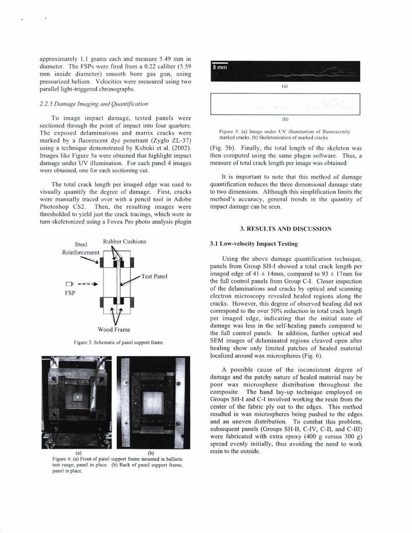
approximately 1.1 grams each and measure 5.49 mm indiameter. The FSPs were fired from a 0.22 caliber (5.59mm inside diameter) smooth bore gas gun, usingpressurized helium. Velocities were measured using twoparallel light-triggered chronographs. (a)
2.2.3 Damage Imaging and Quantification
To image impact damage, tested panels were (b)sectioned through the point of impact into four quarters.The exposed delaminations and matrix cracks were Figure 5: (a) Image under UV illumination of fluorescently
marked by a fluorescent dye penetrant (Zyglo ZL-37) marked cracks. (b) Skeletonization of marked cracks.
using a technique demonstrated by Kuboki et al. (2002). (Fig. 5b). Finally, the total length of the skeleton wasImages like Figure 5a were obtained that highlight impact then computed using the same plugin software. Thus, adamage under UV illumination. For each panel 4 images measure of total crack length per image was obtained.were obtained, one for each sectioning cut.
It is important to note that this method of damageThe total crack length per imaged edge was used to quantification reduces the three dimensional damage state
visually quantify the degree of damage. First, cracks to two dimensions. Although this simplification limits thewere manually traced over with a pencil tool in Adobe method's accuracy, general trends in the quantity ofPhotoshop CS2. Then, the resulting images were impact damage can be seen.thresholded to yield just the crack tracings, which were inturn skeletonized using a Fovea Pro photo analysis plugin
3. RESULTS AND DISCUSSION
Steel Rubber Cushions 3.1 Low-velocity Impact Testing
ReinforcementUsing the above damage quantification technique,
panels from Group SH-I showed a total crack length per
Test Panel imaged edge of 41 ± 14mm, compared to 93 ± 17mm forS7 the full control panels from Group C-I. Closer inspection
of the delaminations and cracks by optical and scanningFSP--electron microscopy revealed healed regions along the
cracks. However, this degree of observed healing did notcorrespond to the over 50% reduction in total crack lengthper imaged edge, indicating that the initial state of
Wood Frame damage was less in the self-healing panels compared tothe full control panels. In addition, further optical and
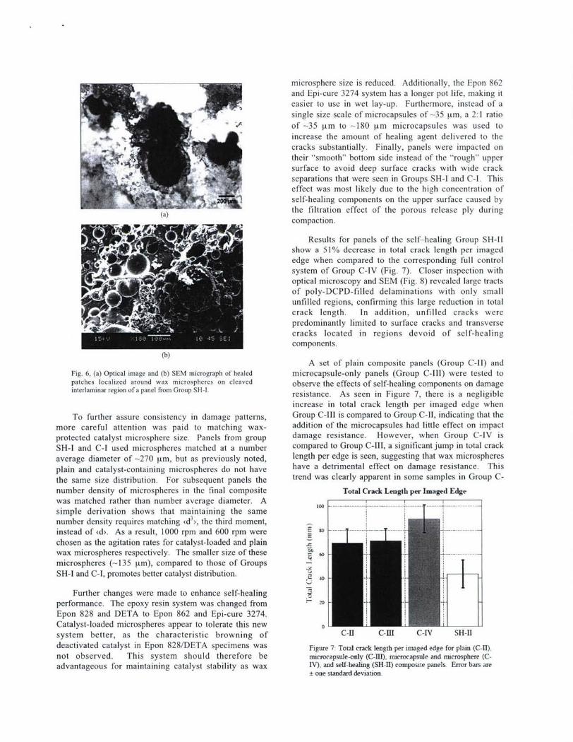
Figure 3: Schematic of panel support frame. SEM images of delaminated regions cleaved open afterhealing show only limited patches of healed materiallocalized around wax microspheres (Fig. 6).
A possible cause of the inconsistent degree ofdamage and the patchy nature of healed material may bepoor wax microsphere distribution throughout thecomposite. The hand lay-up technique employed onGroups SH-I and C-I involved working the resin from thecenter of the fabric ply out to the edges. This methodresulted in wax microspheres being pushed to the edgesand an uneven distribution. To combat this problem,subsequent panels (Groups SH-II, C-IV, C-Il, and C-11I)were fabricated with extra epoxy (400 g versus 300 g)spread evenly initially, thus avoiding the need to work
(a) (b) resin to the outside.Figure 4: (a) Front of panel support frame mounted in ballistictest range, panel in place. (b) Back of panel support frame,panel in place.
microsphere size is reduced. Additionally, the Epon 862and Epi-cure 3274 system has a longer pot life, making iteasier to use in wet lay-up. Furthermore, instead of asingle size scale of microcapsules of -35 pm, a 2:1 ratio"of -35 [tm to -180 pm microcapsules was used toincrease the amount of healing agent delivered to thecracks substantially. Finally, panels were impacted ontheir "smooth" bottom side instead of the "rough" upper
surface to avoid deep surface cracks with wide crackseparations that were seen in Groups SH-1 and C-I. Thiseffect was most likely due to the high concentration ofself-healing components on the upper surface caused by
(a) the filtration effect of the porous release ply duringcompaction.
Results for panels of the self-healing Group SH-11show a 51% decrease in total crack length per imagededge when compared to the corresponding full controlsystem of Group C-IV (Fig. 7). Closer inspection withoptical microscopy and SEM (Fig. 8) revealed large tractsof poly-DCPD-filled delaminations with only smallunfilled regions, confirming this large reduction in totalcrack length. In addition, unfilled cracks werepredominantly limited to surface cracks and transversecracks located in regions devoid of self-healingcomponents.
(b)A set of plain composite panels (Group C-Il) and
Fig. 6, (a) Optical image and (b) SEM micrograph of healed microcapsule-only panels (Group C-Ill) were tested topatches localized around wax microspheres on cleaved observe the effects of self-healing components on damageinterlaminar region of a panel from Group SH-l. resistance. As seen in Figure 7, there is a negligible
increase in total crack length per imaged edge when
To further assure consistency in damage patterns, Group C-Ill is compared to Group C-lI, indicating that themore careful attention was paid to matching wax- addition of the microcapsules had little effect on impact
protected catalyst microsphere size. Panels from group damage resistance. However, when Group C-IV is
SH-I and C-I used microspheres matched at a number compared to Group C-Ill, a significant jump in total crack
average diameter of -270 ptm, but as previously noted, length per edge is seen, suggesting that wax microspheres
plain and catalyst-containing microspheres do not have have a detrimental effect on damage resistance. This
the same size distribution. For subsequent panels the trend was clearly apparent in some samples in Group C-
number density of microspheres in the final composite Total Crack Length per Imaged Edgewas matched rather than number average diameter. A I Isimple derivation shows that maintaining the samenumber density requires matching <d3 >, the third moment,instead of <d>. As a result, 1000 rpm and 600 rpm were E
chosen as the agitation rates for catalyst-loaded and plainwax microspheres respectively. The smaller size of these 60 . .microspheres (-135 pAm), compared to those of Groups -
SH-1 and C-I, promotes better catalyst distribution.
Further changes were made to enhance self-healingperformance. The epoxy resin system was changed from ""Epon 828 and DETA to Epon 862 and Epi-cure 3274.Catalyst-loaded microspheres appear to tolerate this newsystem better, as the characteristic browning of C-II C-III C-IV SH-IIdeactivated catalyst in Epon 828/DETA specimens was Figure 7 Total crack length per imaged edge for plain (C-11).not observed. This system should therefore be microcapsule-osily (C-m), microcapsule and microsphere (C-advantageous for maintaining catalyst stability as wax IV), and self-healing (SH-II) composite panels- Error bars are
t one standard deviation-
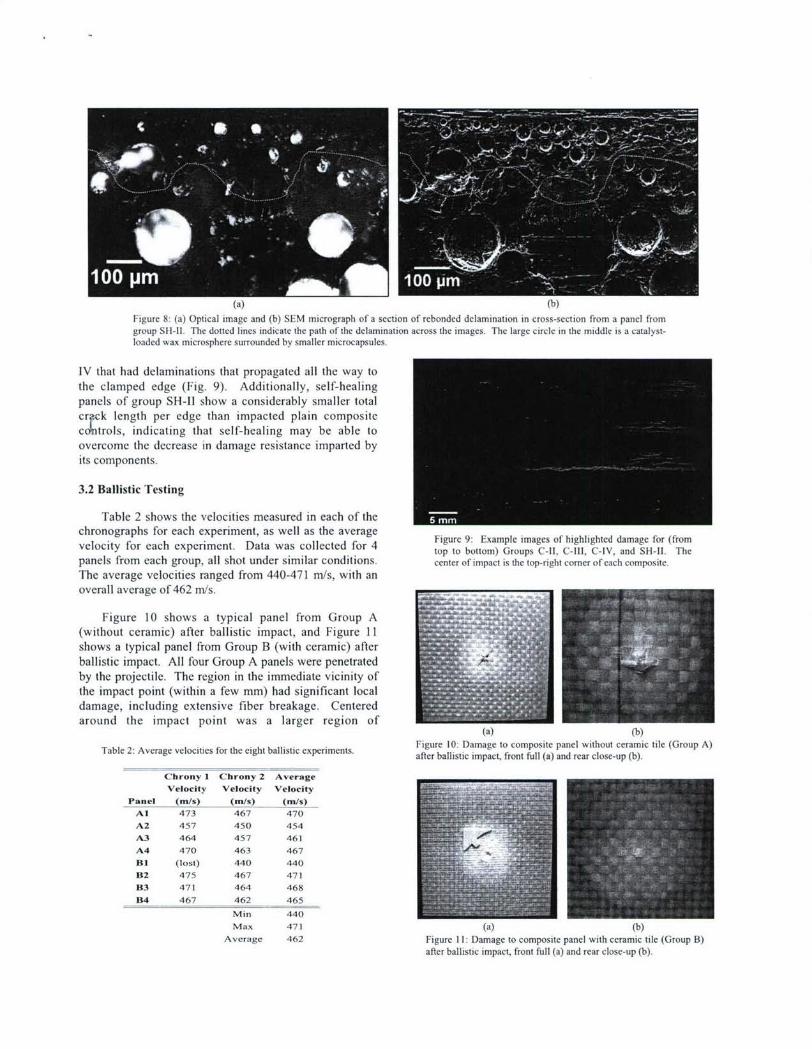
(a) (b)
Figure 8: (a) Optical image and (b) SEM micrograph of a section of rebonded delamination in cross-section from a panel fromgroup SH--l. The dotted lines indicate the path of the delamination across the images. The large circle in the middle is a catalyst-loaded wax microsphere surrounded by smaller microcapsules.
IV that had delaminations that propagated all the way tothe clamped edge (Fig. 9). Additionally, self-healingpanels of group SH-11 show a considerably smaller totalcr k length per edge than impacted plain compositecodntrols, indicating that self-healing may be able toovercome the decrease in damage resistance imparted byits components.
3.2 Ballistic Testing
Table 2 shows the velocities measured in each of thechronographs for each experiment, as well as the average Figure 9: Example images of highlighted damage for (from
velocity for each experiment. Data was collected for 4 top to bottom) Groups C-Il, C-Ill, C-IV, and SH-II. The
panels from each group, all shot under similar conditions, center of impact is the top-right comer of each composite.
The average velocities ranged from 440-471 m/s, with anoverall average of 462 m/s.
Figure 10 shows a typical panel from Group A(without ceramic) after ballistic impact, and Figure 11shows a typical panel from Group B (with ceramic) afterballistic impact. All four Group A panels were penetratedby the projectile. The region in the immediate vicinity ofthe impact point (within a few mm) had significant localdamage, including extensive fiber breakage. Centeredaround the impact point was a larger region of
(a) (b)
Table 2: Average velocites for the eight ballistic expeniments. Figure 10: Damage to composite panel without ceramic tile (Group A)after ballistic impact, front full (a) and rear close-up (b).
Chrony I Chrony 2 AverageVelocity Velocity Velocity
Panel (mis) (m/s) (m/s)
Al 473 467 470
A2 457 450 454
A3 464 457 461
A4 470 463 467
BI (lost) 440 440
B2 475 467 471
B3 471 464 468
B4 467 462 465
Min 440
Max 471 (a) (b)
Average 462 Figure 11: Damage to composite panel with ceramic tile (Group B)after ballistic impact, front full (a) and rear close-up (b).
delamination, visible as a whitening of the composite.This area was approximately 50-65 mm in diameter.Some permanent deformation of the composite in thisregion was visible as a slight bowing in the glass-epoxylaminate.
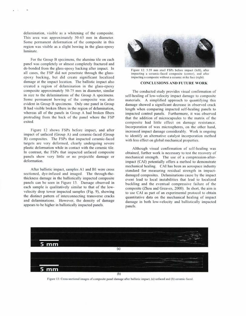
For the Group B specimens, the alumina tile on eachpanel was completely or almost completely fractured andde-bonded from the glass-epoxy backing after impact. In Figure 12: 5.59 mm steel FSPs before impact (left), afterall cases, the FSP did not penetrate through the glass- impacting a ceramic-faced composite (center), and after
epoxy backing, but did create significant localized impacting a composite without a ceramic strike face (right).
damage at the impact location. The ballistic impact also CONCLUSIONS AND FUTURE WORKcreated a region of delamination in the glass-epoxycomposite approximately 50-75 mm in diameter, similar The conducted study provides visual confirmation ofin size to the delaminations of the Group A specimens. self-healing of low-velocity impact damage to compositeSome permanent bowing of the composite was also materials. A simplified approach to quantifying thisevident in Group B specimens. Only one panel in Group damage showed a significant decrease in observed crackB had visible broken fibers in the region of delamination, length when comparing impacted self-healing panels towhereas all of the panels in Group A had broken fibers impacted control panels. Furthermore, it was observedprotruding from the back of the panel where the FSP that the addition of microcapsules to the matrix of theexited. composite had little effect on damage resistance.
Incorporation of wax microspheres, on the other hand,Figure 12 shows FSPs before impact, and after increased impact damage considerably. Work is ongoing
impact of unfaced (Group A) and ceramic-faced (Group to identify an alternative catalyst incorporation methodB) composites. The FSPs that impacted ceramic-faced with less effect on global mechanical properties.targets are very deformed, clearly undergoing severeplastic deformation while in contact with the ceramic tile. Although visual confirmation of self-healing wasIn contrast, the FSPs that impacted unfaced composite obtained, further work is necessary to test the recovery ofpanels show very little or no projectile damage or mechanical strength. The use of a compression-after-deformation, impact (CAI) potentially offers a method to demonstrate
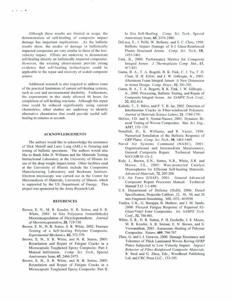
mechanical healing. CAI has been an aerospace industryAfter ballistic impact, samples Al and BI were cross standard for measuring residual strength in impact-
sectioned, dye-infused and imaged. The through-the- damaged composites. Delaminations cause by the impactthickness damage in the ballistically impacted composite event lead to local instabilities that lead to localizedpanels can be seen in Figure 13. Damage observed in buckling and the eventual compressive failure of theeach sample is qualitatively similar to that of the low- composite (Zhou and Greaves, 2000). In short, the aim isvelocity drop tower impacted samples (Fig. 9), showing to use CAl as part of an experimental protocol to obtainthe distinct pattern of interconnecting transverse cracks quantitative data on the mechanical healing of impactand delaminations. However, the density of damage damage in both low-velocity and ballistically impactedappears to be higher in ballistically impacted panels. panels.
(a)
(b)
Figure 13: Cross-sectional images of composite panel damage after ballistic impact, (a) unfaced and (b) ceramic-faced.
Although these results are limited in scope, the In Situ Self-Healing. Comp. Sci. Tech., Specialdemonstration of self-healing of composite impact Anniversary Issue, 65, 2474-2480.damage has important implications. As the ballistic DeLuca, E., J. Prifti, W. Betheny, and S. C. Chou, 1998:results show, the modes of damage in ballistically Ballistic Impact Damage of S-2 Glass-Reinforcedimpacted composites arc very similar to those of the low- Plastic Structural Armor. Comp. Sci. Tech., 58,velocity impact. Efforts are underway to demonstrate 1453-1461.self-healing directly on ballistically impacted composites. Fink, B., 2000: Performance Metrics for CompositeHowever, the existing observations provide strong Integral Armor. J. Thermoplastic Comp. Mat., 13,evidence that self-healing technologies could be 417-431.applicable to the repair and recovery of scaled composite Gama, B. A., T. A. Bogetti, B. K. Fink, C. J. Yu, T. D.armors. Claar, H. H. Eifert, and J. W. Gillespie, Jr., 2001:
Aluminum Foam Integral Armor: A New DimensionAdditional research is also required to address some in Armor Design. Comp. Struct., 52, 381-395.
of the practical limitations of current self-healing systems, Gama, B. A., T. A. Bogetti, B. K. Fink, J. W. Gillespie,such as cost and environmental durability. Furthermore, Jr., 2000: Processing, Ballistic Testing, and Repair ofthe experiments in this study allowed 48 hours for Composite Integral Armor. Int. SAMPE Tech. Conf.,completion of self-healing reactions. Although this repair 32, 802-814.time could be reduced significantly using current Kuboki, T., T. Hilvo, and P. Y. B. Jar, 2002: Detection ofchemistries, other studies are underway to identify Interlaminar Cracks in Fiber-reinforced Polymers.alternative chemistries that could provide useful self- Journal of Materials Science Letters, 21, 1789-1791.healing in minutes or seconds. McGee, J.D. and S. Nemat-Nasser, 2001: Dynamic Bi-
axial Testing of Woven Composites. Mat. Sci. Eng.,A317, 135-139.
Nandlall, D., K. Williams, and R. Vaziri, 1998:ACKNOWLEDGEMENTS Numerical Simulation of the Ballistic Response of
GRP Plates. Comp. Sci. Tech., 58, 1463-1469.The authors would like to acknowledge the assistance Naval Air Systems Command (NASC), 2001:
of Dick Merrill and Larry Long (ARL) in fixturing and Organizational and Intermediate Maintenance,
testing of ballistic specimens. The authors would also ganeral andoIterepate M ance,
like to thank John D. Williams and the Materials Testing NAVAIR 01-iA-2.
Instructional Laboratory at the University of Illinois for E.
use of the drop weight impact tester. Other facilities used Mooe , Jrow , 2005: Wax-pr otected Catalyst
at the University of Illinois include the Composites Microspheres for Efficient Self-healing Materials.
Manufacturing Laboratory and Beckman Institute.
Electron microscopy was carried out in the Center for Advanced Materials, 72, 205-208.U.S. Air Force (USAF), 2001: General Advanced
Microanalysis of Materials, University of Illinois, which Composite Repair Processes Manual. Technicalis supported by the US Department of Energy. This Manual T.O. 1-1-690.project was sponsored by the Army Research Lab. U.S. Department of Defense (DoD), 2006: Detail
Specification, Projectile Calibers .22, .30, .50, and 20mm Fragment-Simulating. MIL-DTL-46593B.
REFERENCES Vaidya, U.K., G. Basappa, B. Mathew, and J. M. Sands,2000: Flexural Fatigue Response of Repaired S2-
Brown, E. N., M. R. Kessler, N. R. Sottos, and S. R. G las/Vn l Este C es. ot SaMPe TehWhit, 203:In ituPol~ura frmadehde)Glass/Vinyl Ester Composites. Int. SAMPE Tech.
White, 2003: In Situ Poly(urea formaldehyde) Conf, 32, 788-801.Microenicapsulation of Dicyclopentadiene. Journal of,3,7801ofMicroencapsulation of, Dicyc9op n. JWhite, S. R., N. R. Sottos, P. H. Geubelle, J. S. Moore,of Microencapsulation, 20, 7 19-730. M. R. Kessler, S. R. Sriram, E. N. Brown, and S.
Brown, E. N., N. R. Sottos, S. R. White, 2002: Fracture Viswanashan, 2001: Autonmc EalNg of PolymeTestng f a elfhealng olymr Cmposte.Viswanathan, 2001: Autonomic Healing of Polymer
Testing of a Self-healing Polymer Composite. Composites. Nature, 409, 794-797Experimental Mechanics, 42, 372-379. Zhou, G. and L.J. Greaves, 2000: Damage Resistance and
Brown, E. N., S. R. White, and N. R. Sottos, 2005: Tolerance of Thick Laminated Woven Roving GFRP
Retardation and Repair of Fatigue Cracks in a Plates Subjected to Low Velocity Impact. Impact
Microcapsule Toughened Epoxy Composite- Part 1:PltsSbeedoLwVlciyIpt.matMicrocapsual Toughened.Epox Comp osiTe-h, Speart Behavior of Fibre-Reinforced Composite Materials,Manual Infiltration. Comp. Sci. Tech., Special R. Reid and G. Zhou, Eds., Woodhead Publishing
Anniversary Issue, 65, 2466-2473. Ltd. and CRC Press LLC., 133-185.
Brown, E. N., S. R. White, and N. R. Sottos, 2005:
Retardation and Repair of Fatigue Cracks in aMicrocapsule Toughened Epoxy Composite- Part II: