sem iii - spce.ac.in
TRANSCRIPT

s.'. . 5 11Bharatiya Vidya 1Thavan's
S:1 'liar Patel College of Engineering
(A Government Aided Autonomous Institute)
Munshi Nagar Andheri (West), Nilunibai — 40005
END SEM ESTER Examination
November 2017
1()
1- \ 1 \
Maximum Marks: 100 Duration: 3 hour
Class: S.Y.13.Tech Semester: Ill Program :Mechanical Engineering
Name of the Course: Applied Mathematics III Course Code : WIM301
ricks-1--cr cf )(-- •
Instructions:
• Attempt any FOUR questions out of remaining SIX questions. • Question number.1 is compulsory.
• Answers to all sub questions should be grouped together.
Q Marks
5
CO Module No.
1(a) If A =
theorem.
_ 3
_ 2
0 1_, find A2° -2A19 + A. using cayley Hamilton
7
(b) Find Laplace transforms or f(t) = sin' i 5
(c) Obtain
f (x) =
the Fourier series for
I ')x
1+- —7C<X< 0
5 2 ,
it
2x , — u<x<TC it
(d) Find the image of the area between x2 + y2 = 4 and
x2 + y2 =9 in the z — plane into the w — plane under the
transformation w . log z
5 3 5
2 (a) Find the eigen values and eigen vectors of the matrix. 6 4 7
6
3 (a)
(b)
Prove that the following function is analytic
gz)., cosh z I-
0 )
Show that the matrix A = —c 0 a satisfies Cayley-
b —a 0
(c)
Hamilton's theorem
Find L d (1—cos 2/11
4 (a) Find the Fourier series for f (x)
o rc x s: 0
0 < x <
(b) Find. the Laplace transforms of f(t), where
f(t) t2'
< t < 1
IL 0, > 1
8
If f (z) is a regular function of z, prove that
n2 n2 .\\
2 u f (z)I2 = 41f . Ox ay2
(c)
5 (a) s2 + b2
s2 + a2 f
{Evaluate: L-1 log
A=
—6
—6 7 —4
—4 3
sin 21+ sin3i Prove that 1--- di =
let 4
(c) If f (x) = x 0 ._-: x 7-..,: 2
Find half range cosine series using Parseval's identity deduce
n4 I
I 1 - ---------------- 96 14 3' 54
(b)

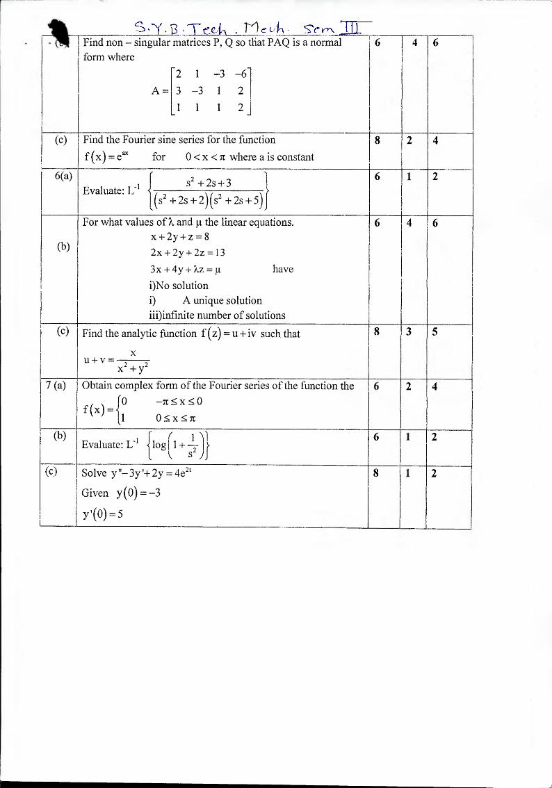
, - (0) I Find non -- sinti,tiktr
form where
A::
matrices 1), Q so
2 1 —.3 - 6
3 —3 1 2
I 1 2
dial PAQ is a normal 6 4 6
(c) -- Find the Fourier sine series for the function
f (x) — e" for 0 < x < 7r where a is constant -
6(a) s2
± 2s -I-3 Evaluate: 1,
8
(2 k2s+-2)(s2 +2s+5)f h--
(b)
7or what values °IX and IA the linear equations. x + 2y + z = 8
2": 4 2y -i- 2z = 13
3x -t 4y + ki = p. have
i)No solution
i) A unique solution
iii)infinite number of solutions _
3
......
(c) Find the analytic function 1(z) = u +iv such that 1
x u+v =
I-- x 2 +y2
7 (a) Obtain complex form of the Fourier series of the function the
f(x)= i° 6 2
,
(b) -1 f ( i 1 11 Evaluate: L )log l A ÷ -T I s)
1 2
c) I Solve y "-3y'+ 2y = 4?
Given y(0)=-3
y'(0) = 5
8 --f----
1

,fTecks. Bharatiya Vidya Bhavan's
Sardar Patel College of Engineering (A Government Aided Autonomous Institute)
Munshi Nagar, Andheri (West), Mumbai — 400058
END SEMESTER
NOVEMBER 2017
Program: B.Tech Second Year Mechanical
Course code: BTM304
Name of the Course: Material Science Semester: III
Viks+er e ,
Date: 20/11/2017
Duration: 3 hours
Maximum Marks: 100
_Instructions:
+ Q. No. I is compulsory.
+ Attempt any FOUR questions out of six.
+ Illustrate the answers with sketches wherever required.
+ Answers to all sub questions should be grouped together.
Question No.
Maximum Marks
Course Outcome Number
Module No.
Q1 A
What are refractory materials? state the basic properties and uses also write what do you understand by (a) Glass (b) Abrasives
10 04 06
, Explain the effects of carbon and various alloying elements added to (a) Carbon steels & (b) Alloy steels
10 01 05
Q2 A Draw neat labeled diagram of Fe-Fe3C and explain various reactions observed in details.
12 03 02
B What is heat treatment? Why are the steels heat treated? How would you classify the types of heat treatment processes?
08 04 1
04
Q3A Differentiate between edge dislocation and screw dislocation. Illustrate with sketches.
08 02 03
B
Determine the ASTM grain size number if 30 grains per square inch are measured at a magnification of 250.
06 02 03
1
,
Q4 A Draw an Eutectic phase diagram and explain it. 08 03 1 02
B Explain advance materials and their
applications. 06 1 01 01
C Draw and properly label the T-T-T diagram of plain carbon steel.
06 03 02
Q5 A Why are ceramics brittle, while metals are ductile? Discuss under what condition a ductile
metal can become brittle? 06 04 06
B usage.
Discuss environmental considerations of material usage and social issue of material 08 01 07
C Cite four reasons why martensite is so hard and brittle.
06 03 02
Q6 A
Write short notes on any two of the following:
05 04 05 04 05 04
06 06 06
1. Composite materials and its applications. 2. Nano Materials and their two unique properties. 3. Plasting processing techniques.
B Define Phase, Phase rule, Isomorphous system, Burger vector and Creep Curve.
1 10 02 04
Q7
Two metals A (melting point 900 C) and B (melting point 600 C) form a eutectic at 400 C with a composition 40 wt.% A. The metal A is soluble to B to the extent of 5 wt.% A at room temperature which increases to 20 wt.% A at the eutectic temperature. Metal B is not soluble to A in the solid state.
A Construct the phase diagram for metals A and B and label all points, lines and areas. 10 03 02
B
(a) Indicate the start and end of solidification temperatures. 2 (b) Determine the compositions and relative amounts of the phases present at 300 C.
10 03 02
*A11 The Best *
2

B Teal • 71 ecit. BharatiyaVidya Bhavan's
Sardar Patel College of Engineering (A Government Aided Autonomous Institute)
Munshi Nagar, Andheri (West), Mumbai -- 400058.
ENDSEM November 201.7
Class: S. Y. B. Tech (Mechanical).
Course: Machine Drawing Course Code: BTM303
Note:
• Question no. 1 is compulsory. • Attempt any four out of remaining six questions. • Use only drawing sheet to answer. • Assume suitable data if necessary.
Total Marks: 100
Time: 3 hrs
cts 4-cr .
No. Module /CO.No.
Marks
Q.1 (a) A vertical cylinder, base 100 mm diameter, is penetrated by a horizontal cylinder of 50 mm diameter, the axis of the horizontal cylinder is parallel to the H.P. and V.P. and 8 mm away from the axis of the vertical cylinder. Draw the projections showing curves of intersections.
01/03 14
(b) Draw Free Hand Sketches of: i) Wing Nut ii) Hook Bolt
02/02 06 -
Q.2 (a) Given in Figure 1 is Front View, Partial Side View and Partial Auxiliary View. Draw the Following by First Angle Method
i) Front View ii) Partial 'Top View iii) Full Auxiliary View
01/03
2 3 7
(b) Show different types or fi ts via hole basis system and Define each of them?
02/02 02 06
Q.3 (a) Given in Figure 2 is the assembly drawing of Knuckle Joint. Draw detail drawing of the following parts.
I) Fork F,nd Sectional Front View and Top View ii) Single Eye End — Sectional Front View and Top View
03/01
08 08
(b) Draw free hand sketches of following types of threads:
(i) Witworth Thread ii) Buttress Thread
04
0.4 (a) Given in the Figure 3 is the detail drawing of Protective Flange Coupling. Draw the following views of assembly drawing:
(i) Sectional Front View (ii) Rill of Material
04/01
03/02
10 04
06 (b) Draw the free hand sketches of the following:
i) Feather Key ii) llollow saddle key

, 411/,1 a
deviation in inicro „ I ,
in microns
is k4 to k7
in
-1-0.63D1/2
+ (177 1T6)
_16D 0,44
n0.41
± (IT /2)
+5,034
+ (1T7 + 0 to 5)
_2.5D0.34
0
11
--' ' I ' Li ' I c____ c..4-1 , , ; c _
Q.5 I (a) Given in the Figure 4 is the partial sectional front view of V-Belt Pulley. Draw the following views:
i) Sectional Front View ii) Side View
05/03
06 08
-- (b) Draw the conventional representation of the following bearings:
(i) Ball bearing (ii) Roller bearing (iii) Thrust bearing
04/02 02 02 02
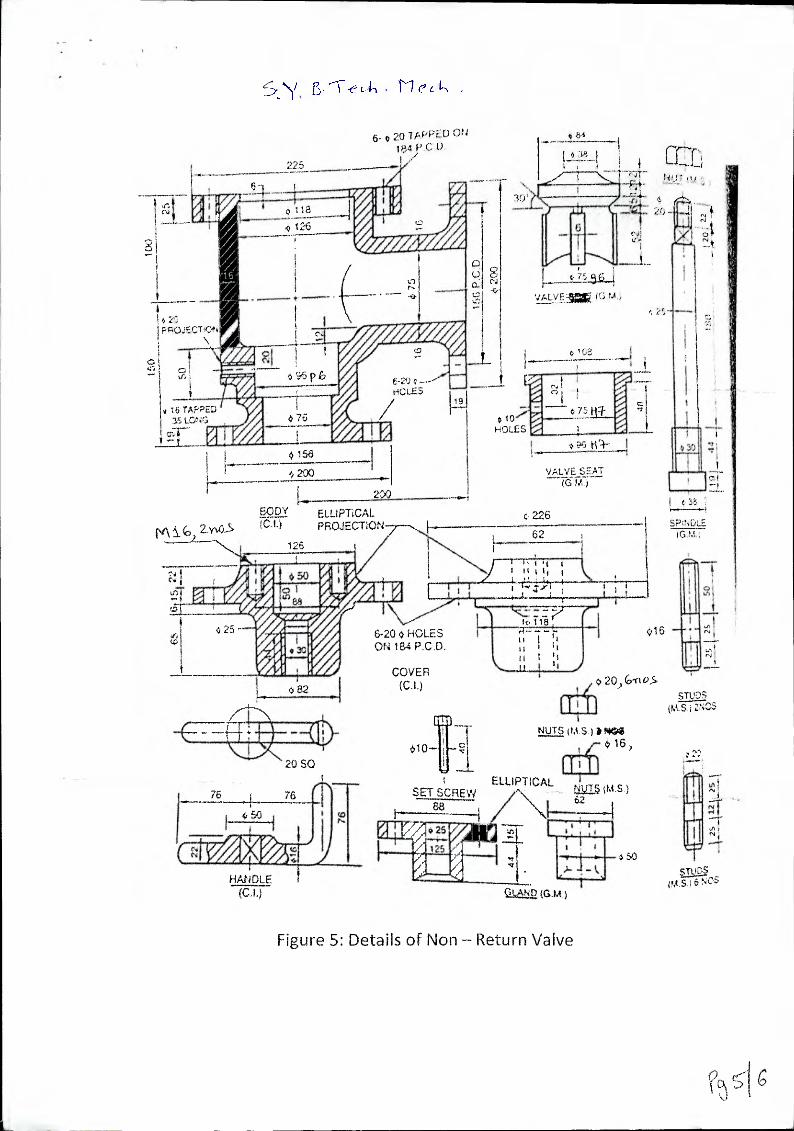
06/01 Q.6 Given in the Figure 5 is the detail drawing of non — return valve. Imagine
the parts assembled and draw the following:
a) Sectional Front View b) Bill of Material c) Calculate tolerance between valve and valve seat
12
04 ,
_ 04 i
Q.7
i
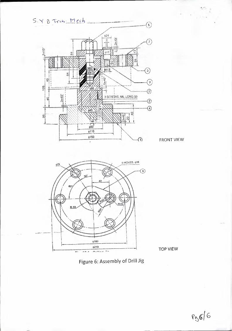
Given in Figure 6 is the assembly of Drill Jig. Draw the detail views of following parts:
a) Jig Plate - i) Sectional Front View ii) Top View
b) Base — Sectional Front View c) Latch Washer — Top View
07/01
06, 06 04 04
Limits, Tolerance Tables Table 1 Recommended diameter steps upto 500 mm (13 steps)
Over - 3 6 10 18 30 [ 50 80 120 180 1 250 315 400_j 11,.1pto 3 6 10 18 30 50 I 80 120 180 250 315 400 500 I
Table 2 Equations to calculate fundamental deviation of shaft size up to 500 mm (D
Geometrical mean dia. in mm)
Fundamental Tolerance for IT grades in terms or i.
--I IT (k I! 115 ' 116 _117 1T8 119 1110 1111 II 1 IT13 I114 1115 1116
Tolerance :ii 10i 16i 251 40i 1 641 100i 1601 250i 400i 640i 1-0001
in Microns _±, , L ' 1 .,

tie c4-1 -
P20
x'45'
80 100
100 WV
a (/) 0 Co
180 --i-'P 144#,Ng VIEW
80
1 _4)40
30 s 0-
0
0 if) 0 :
0 4) 25
\ OCTAGON I
0 (t) — a
F-315°
Figure 1: Auxiliary View
CNI --TAPER PIN 6 I)IA
45 LONG 440
riZONT ificP VIEW
Afi-Sex4ty Figure 2.: t4.)zt;tif-s of Knuckle Joint

4,24 , 1
4)60 4)110
050 FRONT VIEW
(4I
7-0
NN,
3 SCREWS, M6. LONG 50
0 0,1
•cr
It) 0
+210
t?5 6 HOLES, 418
TOP VIEW
Figure 6: Assembly of Drill Jig
ELLIPTICAL PROJECTION /
ECDY (CA)
125
S', iVTeik ,
6. 20 TAPPED ON PC 0.
225
0.1 0 118 .Q 126
o
1
16 TAPPED
:fa_
i\evi(0, arce0.-S
15.5
- 2C)0
200
t.1 VALVfAkatilr,i
t
C-I
41.10 HOLES
VALVE SEAT SEAT CG-1:k
( 226
62 SPNDLE
GM
15G
PC
. 0
rr' te-‘•••
'.;
Figure 5: Details of Non - Return Valve
o10
SET SCREW 88
NUTS (t.i.S p 16
ELLIPTICAL NV25 {M .S.) \ 62
1 \ 25 WM
4 in FO. Pal 4 HANDLE
(CL)
STLPS (M S ;
I I, i It I Iq I II
6-20 0 HOLES ON 164 P.C.D.
COVER (CI)
016 25 1/4,e/A, or I
• lar o 82
d fsr
et,
1
3 SCREWS, MO, LONG 50 tf) •cr
(Y)
c4)
+60 +110
1 +150
FRONT VIEW
6 HOLES. 408
6
4060
4,210
\R15
TOP VIEW
Figure 6: Assembly of Drill Jig
V416

100 N
0.3m
100 N
s 71ezok Sc yvv_71: Bharatiya Vidya Bhavan's
Sardar Patel College of Engineering (A Government Aided Autonomous Institute)
Munshi Nagar, Andheri (West), Mumbai — 400058
End Semester Examination November 2017
Program: B.Tech. in Mechanical Engineering Class: S.Y. &Tech. (Mechanical) Course code: BTM302 Name of the Course: Strength of Materials Instructions:
Date: Nov 2017 Duration: 3 Hr. Max. Marks: 100 Semester: III
PI e-ts e
Max. CO Module Marks No. No.
Q1 A) A document containing stress vs strain test data for a critical machine component (5) 3 /
was partly damaged and only following data could be retrieved. • Modulus of elasticity = 211 GPa, 0.5% Proof stress = 610 MPa
• Partial stress-strain data:
0.0033 10.0037 0.004 1 Develop the stress-strain curve for the material to the extent possible on a graph paper based on above data and determine the 0.2% proof stress.
B) An indeterminate structure A as shown in the figure consists of beam AB of /,' length L subjected to UDL of I/ w and supported at both ends A and B. Support at A is of fixed type and that at B is of simply supported type. The beam has area M.I. of land modulus of elasticity for material is E. Calculate reactions at supports A and B and draw shear force diagram for the beam, given following information.
• Deflection at the free end of a cantilever beam of length L subjected to
UDL w is given as - 8E1
• Deflection at the free end of a cantilever beam of length L subjected to
point load P acting at its free end is given as - 3E1 C) A beam structure ABCD as
shown in the figure has square cross section of 30 mm x 30 mm. It is fixed at D. Calculate maximum bending stress in the structure.
Page 1 of 4
• Question No 1 is compulsory. Attempt any four questions out of remaining six.
• Answers to all sub questions should be grouped together.
• Assume suitable data if necessary.
505 a (MPa) 590 i 535 560
8 (mm/mm) 0.003
UDL = w
(5) 1 2
(5) 2 4
hi 200 .1 254,
200
S:YB ,Thc4.See1flL
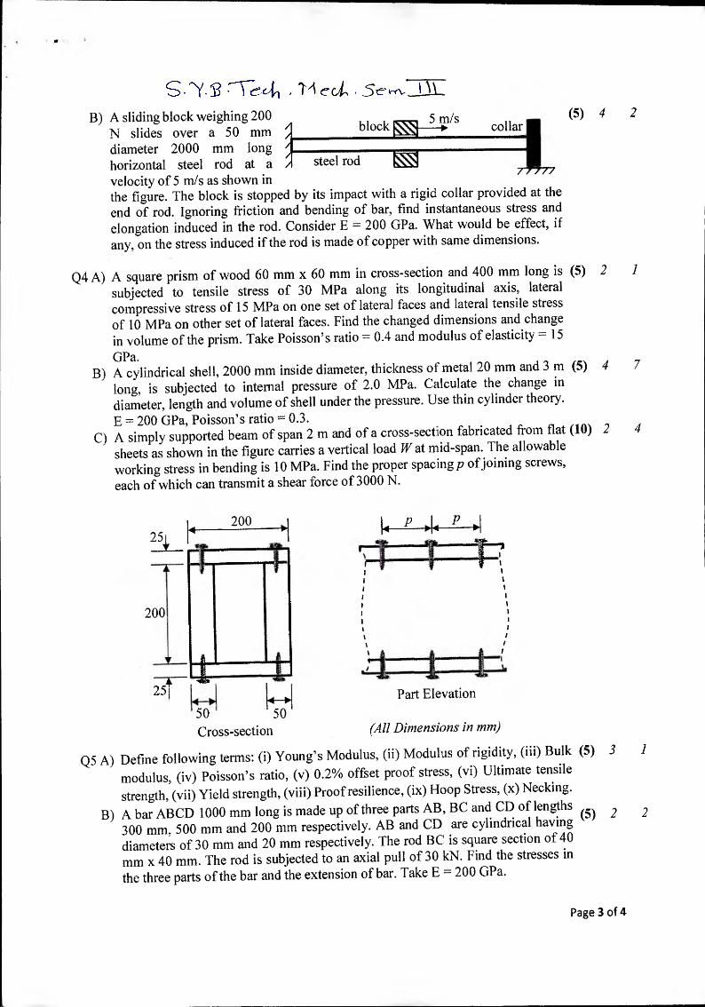
B) A sliding block weighing 200 (5) N slides over a 50 mm block collar
diameter 2000 mm long 1
I
horizontal steel rod at a / steel rod
velocity of 5 m/s as shown in /////
the figure. The block is stopped by its impact with a rigid collar provided at the end of rod. Ignoring friction and bending of bar, find instantaneous stress and elongation induced in the rod. Consider E = 200 GPa. What would be effect, if any, on the stress induced if the rod is made of copper with same dimensions.
Q4 A) A square prism of wood 60 mm x 60 mm in cross-section and 400 mm long is (5) 2 1
subjected to tensile stress of 30 MPa along its longitudinal axis, lateral compressive stress of 15 MPa on one set of lateral faces and lateral tensile stress of 10 MPa on other set of lateral faces. Find the changed dimensions and change in volume of the prism. Take Poisson's ratio 0.4 and modulus of elasticity = 15
GPa. B) A cylindrical shell, 2000 mm inside diameter, thickness of metal 20 mm and 3 m (5) 4 7
long, is subjected to internal pressure of 2.0 MPa. Calculate the change in diameter, length and volume of shell under the pressure. Use thin cylinder theory. E = 200 GPa, Poisson's ratio = 0.3.
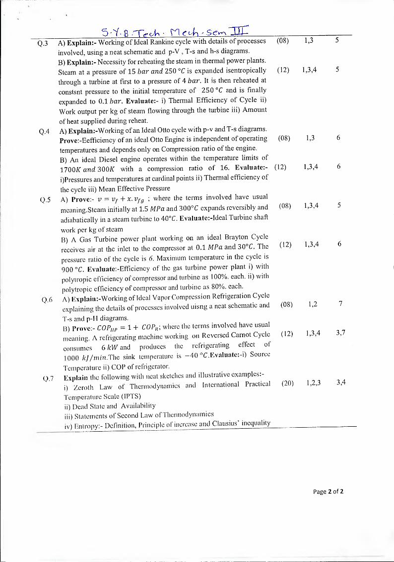
C) A simply supported beam of span 2 m and of a cross-section fabricated from flat (10) 2 4
sheets as shown in the figure carries a vertical load W at mid-span. The allowable working stress in bending is 10 MPa. Find the proper spacing p of joining screws,
each of which can transmit a shear force of 3000 N.
4 2
25
50 14
5C71 Cross-section
P •14 P
Part Elevation
(All Dimensions in mm)
Q5 A) Define following terms: (i) Young's Modulus, (ii) Modulus of rigidity, (iii) Bulk (5) 3 1
modulus, (iv) Poisson's ratio, (v) 0.2% offset proof stress, (vi) Ultimate tensile strength, (vii) Yield strength, (viii) Proof resilience, (ix) Hoop Stress, (x) Necking.
B) A bar ABCD 1000 mm long is made up of three parts AB, BC and CD of lengths 5 2 2 300 mm, 500 mm and 200 mm respectively. AB and CD are cylindrical having
()
diameters of 30 mm and 20 mm respectively. The rod BC is square section of 40 mm x 40 mm. The rod is subjected to an axial pull of 30 kN. Find the stresses in the three parts of the bar and the extension of bar. Take E = 200 GPa.
Page 3 of 4

5 E • Trcit, rvair C) Derive the expression for relationship between rate of loading w, shear force V and (5) 1 3
bending moment M at any point on a transversely loaded beam. D) A 3 mm x 3 mm high strength copper bar 2.5 m long is bent into a circle and held (5) 2 4
with its ends just in contact. Find the maximum bending stress in the bar. Also calculate the bending moment applied at the ends. Take E — 112 GPa.
Q6 A) A cylindrical mild steel bar of 50 mm diameter, 500 mm long is enclosed by a (5) 2 I brass sleeve by brazing. The assembly is subjected to an axial pull of 500 kN. Determine the cross-section area of the brass sleeve so that the sleeve carries 25% of the load. Also determine stresses in the material and the extension of the bar. Eb
= 84 GPa and Es = 210 GPa. B) A steel shaft ABCD of total length of 2 meter is made up as follows: AB = 500 (5) 2 4
mm; BC = 1000 mm; CD = 500 mm. AB is hollow, its outside diameter being 100 mm and its inside diameter d mm. BC and CD are solid, having diameters of 90 and 75 mm respectively. If equal and opposite torques are applied to the ends of the shaft, find the maximum permissible value of d for the maximum shearing stress in AB not to exceed that in CD. If the torque applied to the shaft is 5000 Nm, what is the total angle of twist? 0 = 84 GPa.
C) In a two-dimensional stress system, two mutually perpendicular planes at a point (10) 4 5 carry tensile and compressive stresses ax, cry and shearing stress of 30 MPa. If principal stresses are 30 MPa, tensile and 70 MPa, compressive, determine stresses ax and ay. Also give location a plane with respect to the maximum principal stress plane on which the normal and shear stresses are equal in magnitude and both are positive in sign.
Q7 A) A cantilever beam of length L is subjected to UDL of w acting from support till its (5) 2 6 half-length. Develop expression for the deflection curve of the beam. The beam has area moment of inertia land modulus of elasticity E.
B) A thick-walled cylinder of 200 mm inside diameter is to contain fluid at a pressure (5) 4 7
of 50 MPa. Find the necessary thickness if the maximum hoop stress is not to exceed 200 MPa. If the inner surface becomes corroded and the cylinder has to be re-bored, by how much can the inside diameter be increased without raising by more than 5%, the maximum hoop stress induced by the same internal pressure?
C) A hollow shaft is subjected to a torque of 500 kNm and a bending moment of 250 (5) 4 6
kNm. The internal diameter of the shaft is one-half the external diameter. If the maximum shear stress is not to exceed 100 MPa, find the diameter of the shaft.
D) Describe the Mohr circle method to obtain combined stresses for a two- (5) 4 6 dimensional stress system. Discuss two theories of failure which are used for design of machine components. Which theory of failure you would recommend for design of component made of (i) copper and (ii) cast iron?
oXo
Page 4 of 4

5 Bharatiya Vidya Bhavan's
Sardar Patel College of Engineering (A Government Aided Autonomous Institute)
Munshi Nagar, Andheri (West), Mumbai — 400058
END SEM EXAMINATION
Program: B. Tech. in Mechanical Engineering
Class: Second Year B. Tech. (Mechanical)
Course code: BTM 305
Name of the Course: Thermodynamics
Date: Nove mber-2017
Duration: 3 Hr. Max. Points: 100
Semester: III
Instructions:
• Attempt ANY 05 questions.
• Assume suitable data wherever necessary and state the same.
• Draw neat and lebelled system diagram and/or process diagram
• Legible hand writing, proper figures and tidy work carry weigh
• Refer Steam Tables and Mollier Diagram wherever necessary.
• Answers to theory questions should be brief and prescise.
Q 1 A) Explain:-i) Thermodynamic Equilibrium ii) Quasi-static Process.
Give suitable examples.
B) 1 kg of water in the cylinder —piston arrangement is initially at the
saturated liquid state at 8 bar. It absobs heat from a reservoir at 250 °C.
During the process, the piston moves out in such a way that the pressure
remains constatnt. At the end of the process, water is completely
evaporated to form dry,saturated steam. Evaluate:- i) Heat and Work
Transfer in the process iii) Change in Entropy of the system, reservoir
and universe.
Q 2. A) Discuss:- i) Joule's Experiment ii) I'MM-1 and its Converse.
13) Obtain:-Steady How Energy Equation for a rotary compressor.
Air enters an air compressor at 8 rn/s velocity, 100 kPa pressure and
volume of 0.95 mYkg. It flows steadily at the rate of 0.6 kg Is and
leaves the compressor at 6 m/s, 700 kPa pressure and volume of
0.19 TrI3 /kg. The internal energy of the air leaving the compressor is
90 kJ/kg more than that of the air entering the compressor. The cooling
water in the compressor _jacket absorbs heat from the air in the
compressor at the rate of 60 kW. Evaluate:- i) The ratio of inlet pipe
diameter to outlet pipe diameter ii) The .rate of shaft work input to air
in kW.
Max. Points
CO No.
Module No.
(08) 1
(12) 1,2,4 1,2,4,5
(08) 1,2 2
(12) 1,2,4 2
wherver necessary.
tage.
Page 1 of 2
5.N(-8 ,—"Ceoln ecit-1 • S er-\ Q.3 A) Explain:- Working of Ideal Rankine cycle with details of processes (08) 1,3 5
involved, using a neat schematic and p-V T-s and h-s diagrams. B) Explain:- Necessity for reheating the steam in thermal power plants.
Steam at a pressure of 15 bar and 250 °C is expanded isentropically (12) 1,3,4 5
through a turbine at first to a pressure of 4 bar. It is then reheated at
constsnt pressure to the initial temperature of 250 °C and is finally
expanded to 0.1 bar. Evaluate:- i) Thermal Efficiency of Cycle ii)
Work output per kg of steam flowing through the turbine iii) Amount
of heat supplied during reheat.
Q.4 A) Explain:-Working of an Ideal Otto cycle with p-v and T-s diagrams. Prove:-Eefficiency of an ideal Otto Engine is independent of operating (08)
temperatures and depends only on Compression ratio of the engine. B) An ideal Diesel engine operates within the temperature limits of
1700K and 300K with a compression ratio of 16. Evaluate:- (12)
i)Pressures and temperatures at cardinal points ii) Thermal efficiency of
the cycle iii) Mean Effective Pressure
Q.5 A) Prove:- v = vf + x. vfg ; where the terms involved have usual
meaning.Steam initially at 1.5 MPa and 300°C expands reversibly and (08)
adiabatically in a steam turbine to 40°C. Evaluate:-Ideal Turbine shaft
work per kg of steam 13) A Gas Turbine power plant working on an ideal Brayton Cycle
1,3 6
1,3,4 6
1,3,4 5
1,3,4 6
at 0.1 MPa and 30°C. The (12) receives air at the inlet to the compressor pressure ratio of the cycle is 6. Maximum temperature in the cycle is
900 °C. .Evaluate:-Efficiency of the gas turbine power plant i) with
polytropic efficiency of compressor and turbine as 100%. each. ii) with
polytropic efficiency of compressor and turbine as 80%. each.
Q.6 A) Explain:-Working of Ideal Vapor Compression Refrigeration Cycle
explaining the details of processes involved uisng a neat schematic and
T-s and p-H diagrams.
II) Prove:- COPH p = 1 + COP,; where the terms involved have usual
meaning. A refrigerating machine working on Reversed Carnot Cycle
consumes 6 kW and produces the refrigerating effect of
1000 kJ/rnin.The sink temperature is —40 °C.Evaluate:-0 Source
Temperature ii) COP of refrigerator.
Q.7 Explain the following with neat sketches and illustrative examples:-
i) Zeroth Law of Thermodynamics and International Practical
Temperature Scale (IPTS)
ii) Dead State and Availability
iii) Statements of Second Law of -lhermodynamies
iv) Entropy:- Definition, Principle of increase and Clausius' inequality
(08) 1,2 7
(12) 1,3,4 3,7
(20) 1,2,3 3,4
Page 2 of 2

Lib
2-L-11)itc2-0P*
5,\/.3 , se ryiTIT. BharatiyaVidyaBhavan's
Sardar Patel College of Engineering (A Government Aided Autonomous Institute)
Munshi Nagar, Andheri (West), Mumbai — 400058. End Semester Re-Exam
November 2017 Max. Marks: 100Duration: 3 hours Class: S.Y.B.TECH. Semester:III Program: Mechanical Engineering Name of the Course: Manufacturing Science —1 Course Code : BTM 306 Instructions: cr 1 e 1. Question No 1 is compulsory. 2. Attempt any four questions out of remaining six (each question carries 20 marks) 3. Draw neat schematics diagrams wherever necessary. 4. Assume suitable data if necessary.
Q. No
, Max Mar
k
co # Module no
Q1 (a)
Give an example of super abrasive grinding wheel compositional specification? Give significance of each alpha numeric terms in details which describes grinding wheel?
10 CO1 M6 ,4
b) Draw well labelled neat schematic sketch straight flute drill tool and twisted flute drill tool? Also state difference between them in terms of their geometry, machining capability and applications? For drilling the 50 holes of such pattern in long metal strip (refer figure la. and 1 b.), Suggest the suitable drilling machine can be used for such kind of batch production requirement. Suggest the sequence of drilling operation, cutting tool required for each operation?
10 CO2 M4 ,4
I i I I L7—T" J Lr—r -
i i 1 1 1 I I i
I 1 \ i T-
1 \1 L 7J \ -1 /
1 li it l 1 ii ii
Figure la. Figure lb. Q2 (a)
Draw neat schematic sketch of slotting machine? Explain working principle of slotting machine with schematic sketch? Describe kinematic system of shaper machine? Also draw one geometry of product which can be manufacture by shaper and slotting machine?
I
10 C04 M5
(b) Draw well labelled block diagram of CNC control system? Explain each elements of NC machine tools briefly? The finished part shown in figure no. 1 needs to be manufactured in one setup, in mass production, with desired geometric tolerances has to be satisfied. ,
10 CO2 I M2 ,4
C-N/ • F-v-I - 1) - , , , _ •
Which lathe machine you will prefer to satisfy above mentioned points [1M]? Explain any four important features of that machine which differentiate it from
other lathe machine [4M]?
Figure 2
Q3 Calculate power required to drill 10 mm diameter hole in AISI 1018 material 10 CO2 M4
(a) at feed of 0.20 mm/rev, speed of 250 RPM. Determine volume of metal ,4
removed per unit energy and machining time? Note- Torque required for drilling the hole in AISI 1018 material is given by, T=C X 1°35 X D1.8. where
`C-0.56' is constant for material. Approach and overrun distance equal to 5 mm and half drill point angle if 45°. Draw well labeled sketch of work piece and drill tool indicating working principle of drilling operation?
(b) Give the basic requirements for efficient grinding? 10 CO1 M6
Explain in brief Horizontal spindle rotary table grinder machine along with its ,4
neat schematic sketch and applications? Answer the following question with one or two points only;
Why Silicon carbide abrasive particle grinding wheel cannot be used for grinding steel material? (2M) Give significance of following terms related to grinding wheel a) Grade of hardness, b) Structure? (3M)
Q4 With the help of neat sketch [3M] Explain material removal mechanism [2M] 10 CO3 M7
(a) and characteristics [2M] of "ultrasonic machining" (USM) process? Specify what are different materials and geometries can be machined using this process
[3M]? (b) Draw neat setup sketch of centrifugal casting process and explain its 10 CO3 M1
characteristics? Give its classification and explain any of its subtype with
schematic sketch? Q5 Find the best welding speed to be used for the welding of 8 mm steel plates 10 CO2 M7
(a) with an ambient temperature of 25° C with welding transformer set at 25 V '3 and current passing is 300 A. Arc efficiency is 0.9 and possible travel speeds are 6 to 9 mm/s. limiting cooling rate for satisfactory performance is 6° Cis at
a temperature of 550° C. Data- k= 0.028 Jimm.s.°C, R= 6° Cis, To-- 25° C, 're=
550° C, V= 25 V, I = 300A, h= 8 mm, = 0.9, p*c = 0.0044 J/mm3. °C.
(b) Determine total time required for plain milling of top face and side milling of 1 10 CO1 j M3
other four faces of Aluminum block having length of 300 mm, width 60 mm ,4
and height of 45 mm? Helical fluted plain HSS milling cutter of diameter 70
mm, length 75 mm and have 6 teeth used for plain milling of top surface &Helical fluted solid carbide End milling cutter of diameter 24 mm, length 70 mm and have 6 teeth used for side surface milling. Calculate approach distance and over run distance?cutting velocity 15 mimin and feed is 0.35 mm/tooth.
Q6 A steel manufacturing industry wants to manufacture long billets, blooms etc. (a) I long products of steel material. Suggest a manufacturing process and explain
the basic steps involved with the help of well labelled schematic sketch? Also list down important critical points to be consider for manufacturing of such products?
(b) A cast steel block having length of 850 mm and with 750 mm have thickness of 150 mm. Finish size of block required to have to be of 850X750X130 mm3. For each pass allowable depth of cut for single point tool is 4 mm. Cutting speed maintained is 250 mm/min & return stroke is 450 mmimin. For first two cuts, transverse feed is 5 mm/cutting stroke & for remaining cuts, transverse feed is 3 mm/cutting stroke. Consider approach and over run distance of tool is 5 mm each. Find how long the job will take to complete it? Why it is necessary to select correct ram stroke available on shaper machine [2114]?
Q7 Explain construction working of Universal type of knee and column type (a) conventional milling machine with help of neat schematic sketch?
Also state its special capability (which differ it from other one) in terms of kind of milling operations it can perform?
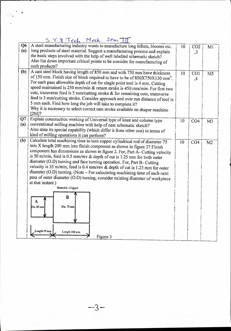
(b) Calculate total machining time to turn copper cylindrical rod of diameter 75 mm X length 200 mm into finish component as shown in figure 2? Finish component has dimensions as shown in figure 2. For, Part A- Cutting velocity is 50 m/min, feed is 0.5 mm/rev & depth of cut is 1.25 mm for both outer diameter (O.D) turning and face turning operation. For, Part B- Cutting velocity is 35 m/min, feed is 0.4 mm/rev & depth of cut is 1.25 mm for outer diameter (0.D) turning. (Note — For calculating machining time of each next pass of outer diameter (0.D) turning, consider existing diameter of workpiece at that instant)
Material - Copper
Length 95 mm Length 100 intu
Figure 3
10 CO2 M1 ,3
10 coilM5 ,4
10 CO4 M3
10 CO4 M2

4 Bharatiya Vidya Bhavan's S;Y, E ut-1 rveA S-e 77F-
Sardar Patel College of Engineering (A Government Aided Autonomous Institute)
Munshi Nagar, Andheri (West), Mumbai 400058.
END SEMESTER Examination
November 2017
Maximum Marks: 100
Duration: 3 hour
Class: S.Y.B.Tech
Semester: III Program:Mechanical Engineering
Name of the Course: Applied Mathematics III Course Code : BTM301
ctsl-e,v-
Instructions:
• Attempt any FOUR questions out of remaining SIX questions. • Question number.1 is compulsory. • Answers to all sub questions should be grouped together.
Q Marks CO Module
No.
1(a) If A =
theorem.
_2 3
_
find A2° -2A19 + A. using cayley Hamilton 5 4 7
(b) Find Laplace transforms of f (t) = sin' t 5 1 1
(c) Obtain
f (x) =
the Fourier series for
')x 1+ — < 0 — 7C < X
5 2 4
7r
, 2x „ 1 ---- v<x< Tr
7L
(d) Find the image of the area between x2 + y2 = 4 and
x2 + y2 =9 in the z — plane into the w — plane under the
transformation w = log z
5 3 5
2 (a) Find the eigen values and cigen vectors of the matrix. 6 4 7

c, ill s • --le c- • • -)
8 —6 2
A=-6 7 —4
2 —4 3
(b) Prove that `1 sin 2t + sin 3t 37r at = —
tet 4 0
2 5
(c) If f (x) = x 0 < x < 2
Find half range cosine series using Parseval's identity deduce
7C4 I 1 1
96 — 14 34 54
5 3 6 3 (a) Prove that the following function is analytic
f(z).-. cosh z 6 4
(b) r 0 c —b7
Show that the matrix A = satisfies Cayley- —c o a
—a 0
Hamilton's theorem
(c) Find L
d (1— cos2t1
dt t
4 (a) 2 4
Find the Fourier series for f (x) = { 0
x
(b) Find the Laplace transforms of f(t), where
f(t)=-{t2 ,0 <t <1
0,1>1
8 (c)
If f (z) is a regular function of z, prove that 32 a2 2 2
a)(2 + ay (Z)1 =4 If"(z)1 .
5 (a) 1 2 6 2 L2
S U {Evaluate: L-1 log s2 a2
set,. III Ili Find non — singular
form where
A =
matrices P, Q so that
2 1 —3 —6-
3 —3 1 2
1 1 1 2 _
FAQ is a normal 6 4
(c) Find the Fourier sine series for the function
f (x) = ea' for 0 < x <r where a is constant
8 2 4
6(a) Evaluate: I:1
s2 +2s+3
(s2 + 2s + 2)(s2 + 2s +5)
For what values of X and IA the linear equations. x+2y+z =8
(b) 2x+2y+2z =13
3x +4y + kz = µ have
i)No solution i) A unique solution iii)infinite number of solutions
(c) Find the analytic
x
function f (z) = u +iv such that 8
u+v= 2 x2 + y
7 (a) Obtain complex form of the Fourier series of the function the
-7E < X < 0 f (x) = {°
1 0 < x < 7C
(b) 1 Evaluate: L-1 {log 11 + --=-- ii
52 )
(c) Solve y "-3y1+ 2y = 4e2t
Given y(0) = —3
y'(0)=5