seminar in honor of professor robert koerner september 13...
TRANSCRIPT

Seminar in Honor of Professor Robert Koerner September 13,2004
1
From Textile to Geotextiles
Frank K. Ko Department of Materials Science and Engineering
Drexel University ABSTRACT A wealth of textile structures is available for a broad range of geotechnical applications. An understanding of the dynamic interaction between the textile structure and the geotechnical environment is essential in the design and selection of textile materials for geotextile applications. Multiaxial warp knit structures and braided structures are introduced as examples of this understanding while demonstrating their potential as multifunctional structural geotextiles. This paper concludes by reviewing a new way of joining geotextiles by robotic one-side stitching technology and by examining the implication of emerging nanofiber technologies for the next generation of geotextiles. INTRODUCTION The name of Professor Robert Koerner is synonymous with geotextiles and geosynthetics. His name is associated with pioneering development in the 1970’s, fueled by his tireless offering of a series of courses in geotextiles in the Philadelphia Engineers Club, around the US and the world. These lectures cumulated in the first book on geotextiles in 1980. At Drexel, he played a leadership role in stimulating the formation of various centers of excellence in 1986, thus officially kicking off the steady growth of the Geotextile Research Institute (GRI) into a leading R&D center for geosynthetics. Professor. Koerner’s tireless efforts in educating generations of civil engineers and textile/polymer material engineers (as well as the creative design and characterization methodologies that he developed) have played a major role in the explosive growth of geotextiles in the past three decades (Figure 1). It would not be exaggerating to honor Professor Koerner by calling this the Koerner Growth Curve.
Figure 1. The Koerner Growth Curve

Seminar in Honor of Professor Robert Koerner September 13,2004
2
Having had the good fortune to attend one of Professor Koerner’s early short courses on Geotextiles at the Philadelphia Engineer’s Club one evening in the late 70’s, I had the benefit of learning from him and knowing him almost from the beginning of the Koerner Curve. Our first collaborative work, presented by Professor Koerner in the 1982 Second International Conference on Geotextiles in Las Vegas, was one of the first attempts to elucidate the long term dynamic interaction of soil and fabrics [1]. He generously helped my team to design and build a long-term soil-fabric constant head flow tester that enabled us to evaluate nonwoven, woven and warp knitted fabrics. For the first time we explored the then-new “multiaxial warp knit textile structures” – the Malimo fabrics, illustrating the hybrid concept for multifunctional geotextiles. At the first GRI Seminar in 1987, I was asked by Professor Koerner to present a review on Seaming and Joining Methods. It turned out to be an excellent preparation for the installation of the latest robotic one-side-stitching facility in our laboratory at Drexel. These early interaction helped open up a new career for me, as a young professor just starting out, in the then new field of Textile Structural Composites, stimulating the use of multiaxial warp knit for aircraft wings and braided structures for stiffeners. Many TSCs such as braided composites also found their way back to geotechnical applications in concrete reinforcements and as reinforced soil columns. It has been an enriching experience to be a colleague and collaborator with Professor Koerner. On the occasion of this seminar celebrating Professor Robert Koerner’s distinguished career, it would be fitting to reflect on some of the early work that he initiated that has a far reaching impact in the field of geotextiles. We will begin with a brief review of textile structures and the properties which make them suitable for geotechnical applications before discussing some early studies on the dynamic interaction between soil and fabrics. Some examples of geotechnical textile structures and composites will be illustrated. This paper will conclude by reviewing some emerging textile materials and processing technologies that may be important for the development of the next generation of geotextiles. TEXTILE STRUCTURES FOR GEOTEXTILES
Geotextiles is a sub-set of industrial textiles or technical textiles. According to the late Kaswell [2], industrial textiles can be categorized according to the form and the manner textile structures are used as outlined below: • Composite Industrial Textiles –textiles are prepared by coating, impregnating,
laminating or other processes not normally undertaken within the textile industry. Examples of products in this category include reinforced rubber; reinforced plastics, metal, ceramics and carbon matrices; abrasive fabrics; asphalt impregnates; etc.
• Processing Industrial Textiles – textile structures used as a component in a manufacturing process. Examples include filtration fabrics such as paper making felts; polishing fabrics; laundry machine aprons etc.
• Direct Use Industrial Textiles – textile structures that are manufactured or incorporated directly into the finished products such as awnings, tarpaulins, marine equipment, outdoor furniture, sporting goods, canvas bags, shoe linings etc.
Seminar in Honor of Professor Robert Koerner September 13,2004
3
Geotextiles fall into the first and the third categories. For many years, industrial textiles were known as ‘mechanical fabrics’ as described by Haven in his 1932 treatise focusing on tire fabrics, balloon fabrics and wing fabrics using woven cotton cord as the primary material [3]. Many industrial textiles have traditionally been produced by members of the Canvas Product Association (CPA) in the US. The diversification of fiber materials and expansion of applications from awning to geotechnical and other industrial applications, as well as the trend in market globalization in the 1970s, led to the reorganization of the CPA to the Industrial Fiber Association International (IFAI), which has played an important role in promoting geotextiles. This transition was highlighted by the introduction of the Journal of Industrial Fabrics in 1982 [4]. Industrial fiber manufacturers such as Owens Corning Fiberglas, duPont, Celanese, Allied, Union Carbide and Dow Corning played an important role in developing the enabling materials and processing technology that supported the growth of the industrial textiles market.
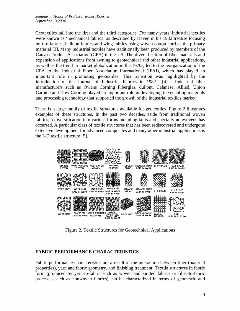
There is a large family of textile structures available for geotextiles. Figure 2 illustrates examples of these structures. In the past two decades, aside from traditional woven fabrics, a diversification into various forms including knits and specialty nonwovens has occurred. A particular class of textile structures that has been rediscovered and undergone extensive development for advanced composites and many other industrial applications is the 3-D textile structure [5].
Figure 2. Textile Structures for Geotechnical Applications
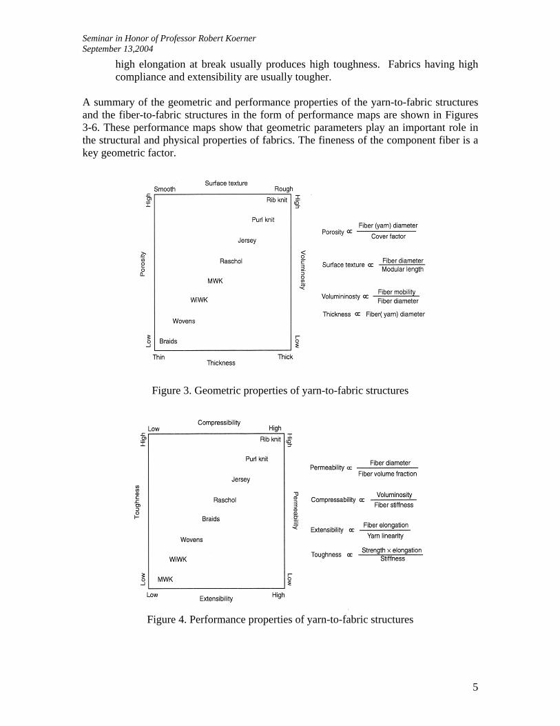
FABRIC PERFORMANCE CHARACTERISTICS Fabric performance characteristics are a result of the interaction between fiber (material properties), yarn and fabric geometry, and finishing treatment. Textile structures in fabric form (produced by yarn-to-fabric such as woven and knitted fabrics or fiber-to-fabric processes such as nonwoven fabrics) can be characterized in terms of geometric and

Seminar in Honor of Professor Robert Koerner September 13,2004
4
performance properties. Performance maps provide an overview of the range of behavior of various fabrics as a function of four geometric parameters and four performance parameters. Geometric parameters include:
1) Porosity: the amount of open space in a unit volume of the fabric. As the fiber diameter and yarn diameter increases, the structure tends to be porous. The porosity of a fabric is inversely proportional to the areal coverage or cover factor of a fabric. A porous fabric tends to be lighter and more permeable. 2) Surface Texture: The surface geometry of a fabric is characterized by the smoothness of the surface, which in turn is governed by fiber and yarn diameter. Modular fiber or yarn length are the geometric repeating units of the fabric. 3) Voluminosity: A reflection of the bulkiness of a fabric for a given areal density (mass per unit area). A fabric tends to be more voluminous if the fiber/yarn diameter is larger and the freedom of fiber mobility in the geometric repeating unit is high. Voluminosity is directly related to fiber thickness in that a voluminous fabric tends to be thick. 4) Thickness of the fabric: Similar to voluminosity, fabric thickness is related to fiber and yarn diameter. The larger the fiber and yarn diameter, the thicker and bulkier the fabric.
Preform parameters include:
1) Permeability: The ease of air or liquid flow through a fabric. The permeability of a fabric is higher when the fabric porosity is high. Porosity and fiber volume fraction (1-porosity) are related to packing efficiency, which is influenced by fiber diameter and fiber cross-sectional geometry. Permeability is a strong function of fiber or yarn diameter for a given fiber architecture (fiber orientation). 2) Compressibility: The ability of a fabric to resist transverse (through the thickness ) compression. A voluminous fabric tends to be more compressible. On the other hand, compressibility decreases as fiber and yarn stiffness, which is significantly influenced by fiber diameter, increases. As fiber diameter increases, the bending stiffness and longitudinal compressive stiffness of the fiber increases geometrically. 3) Extensibility of a fabric: A measure of the ability of a fabric to stretch and conform. Fabric extensibility is affected by fabric geometry and inherent fiber bending elongation. A yarn that consists of finer fibers tends to have a higher potential for fabric extensibility. 4) Toughness of a fabric: A measure of the durability of the fabric. As reflected in the areas under the stress-strain curve of a fabric, a high strength fabric with
Seminar in Honor of Professor Robert Koerner September 13,2004
5
high elongation at break usually produces high toughness. Fabrics having high compliance and extensibility are usually tougher.
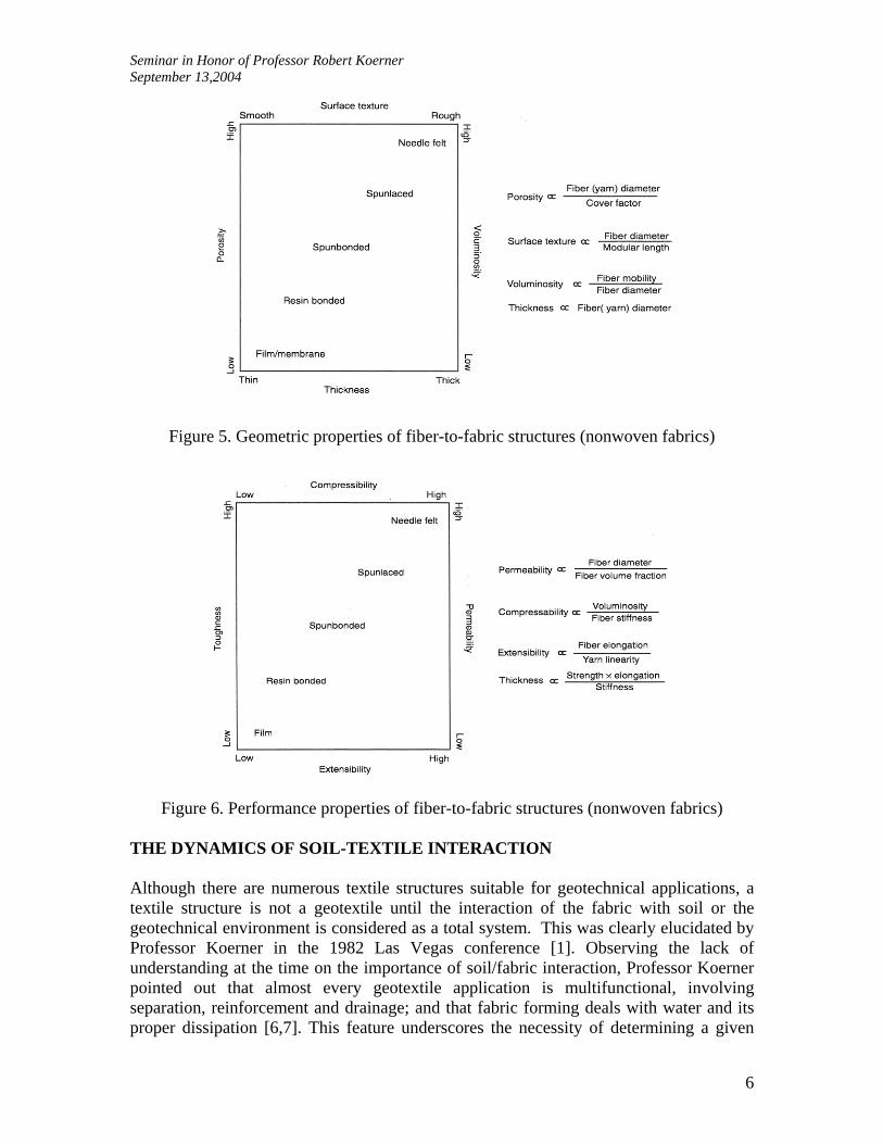
A summary of the geometric and performance properties of the yarn-to-fabric structures and the fiber-to-fabric structures in the form of performance maps are shown in Figures 3-6. These performance maps show that geometric parameters play an important role in the structural and physical properties of fabrics. The fineness of the component fiber is a key geometric factor.
Figure 3. Geometric properties of yarn-to-fabric structures
Figure 4. Performance properties of yarn-to-fabric structures
Seminar in Honor of Professor Robert Koerner September 13,2004
6
Figure 5. Geometric properties of fiber-to-fabric structures (nonwoven fabrics)
Figure 6. Performance properties of fiber-to-fabric structures (nonwoven fabrics) THE DYNAMICS OF SOIL-TEXTILE INTERACTION Although there are numerous textile structures suitable for geotechnical applications, a textile structure is not a geotextile until the interaction of the fabric with soil or the geotechnical environment is considered as a total system. This was clearly elucidated by Professor Koerner in the 1982 Las Vegas conference [1]. Observing the lack of understanding at the time on the importance of soil/fabric interaction, Professor Koerner pointed out that almost every geotextile application is multifunctional, involving separation, reinforcement and drainage; and that fabric forming deals with water and its proper dissipation [6,7]. This feature underscores the necessity of determining a given
Seminar in Honor of Professor Robert Koerner September 13,2004
7
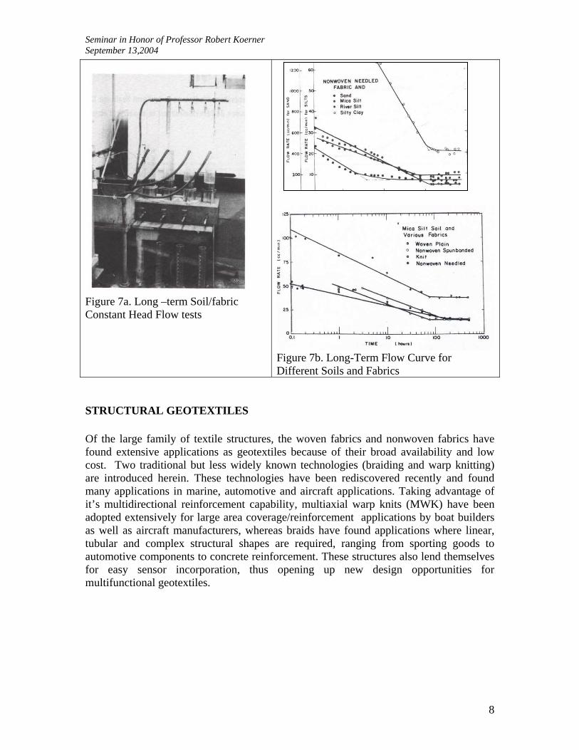
fabrics’ hydraulic properties; more specifically, its flow rate, permeability or permittivity (the permeability divided by thickness). Toward this end, many organizations have recommended test methods and specifications for the laboratory determination of these fabric properties. Note should be made, however, that these procedures are generally for the fabric alone, e.g., ASTM’s “Standard Method for Testing the Water Permeability of Geotextiles – Permittivity Method” as proposed by Subcommittee D13.61 on Geotextiles. While of interest in comparing one fabric to another, these tests have no indication of the hydraulic behavior of the combined soil/fabric system. Professor Koerner went on to explain that, as soon as soil is placed adjacent to the fabric, it is seen that the soils’ hydraulic properties dominate the initial behavior of the system [8, 9, 10]. Only after a period of time does the fabric begin to play a role and, ideally, not at all in the long-term, e.g. when a properly designed configuration exists. In this latter instance, the flow passing through the soil/fabric system becomes constant and an equilibrium situation exists thereafter. To verify and quantify these long-term hydraulic behaviors, a simple test for various soil/fabric systems was established. This system consists of water at a constant head, flowed downward through the soil, then through the fabric and out of the system where it was collected and a flow rate was calculated. Figure 7 shows the apparatus where four tests can be simultaneously performed with sequential variations of either soil or fabric. Using this apparatus we can (1) observe the nature and rate of soil adjustment in the initial flow stages; (2) determine the time required for a given soil/fabric system to reach a stable interactive stage; and, (3) determine if an equilibrium flow situation exists for a wide variety of soils and fabrics in specific soil/fabric configurations. With this information at hand, it then becomes possible to analyze and hypothesize about possible soil/fabric mechanisms that are occurring within the system. The ultimate objective of the proper hydraulic design of soil fabric systems can then be addressed. For example, in a series of experiments using four different fabrics and four different type of soils, as shown in Figure 7b, it can be seen that the initial range of long-term flow tests through soil/fabric interaction systems is governed by soil, and the final range is governed by soil/fabric interaction. It is this final range, as indicated by the slope of the flow curve, that is of primary interest. A zero or nominal slope is preferred over a large slope, since it suggests equilibrium of the soil/fabric structure.
Seminar in Honor of Professor Robert Koerner September 13,2004
8
Figure 7a. Long –term Soil/fabric Constant Head Flow tests
Figure 7b. Long-Term Flow Curve for Different Soils and Fabrics
STRUCTURAL GEOTEXTILES Of the large family of textile structures, the woven fabrics and nonwoven fabrics have found extensive applications as geotextiles because of their broad availability and low cost. Two traditional but less widely known technologies (braiding and warp knitting) are introduced herein. These technologies have been rediscovered recently and found many applications in marine, automotive and aircraft applications. Taking advantage of it’s multidirectional reinforcement capability, multiaxial warp knits (MWK) have been adopted extensively for large area coverage/reinforcement applications by boat builders as well as aircraft manufacturers, whereas braids have found applications where linear, tubular and complex structural shapes are required, ranging from sporting goods to automotive components to concrete reinforcement. These structures also lend themselves for easy sensor incorporation, thus opening up new design opportunities for multifunctional geotextiles.
Seminar in Honor of Professor Robert Koerner September 13,2004
9
Multiaxial Warp Knit
As produced by the Karl Mayer Malimo warp knitting system, the MWK fabric consists of warp (0°), weft (90°), and bias (±θ) yarns plus the option of a nonwoven backing held together by a chain or tricot stitch through the thickness of the fabric, as illustrated in Figure 8a. Aside from the multidirectional and multicomponent nature of the fiber architecture, the MWK is characterized by it’s high productivity, at over 1 meter per minute and a width as wide as three meters. Theoretically, the MWK can be made to as many layers of multiaxial yarns as needed, but current commercially available machines allow four layers (the Karl Mayer system) of 0°, 90°, +θ, and -θ insertion yarns, or six layers (the LIBA Copcentra-multiaxial system) of 2(90°), 0°, 2(+θ), and -θ insertion yarns to be stitched together as shown in Figure 8b. All layers of insertion yarns are aligned linearly in perfect order each on top of the other in the knitting process. Each layer shows the uniformity of the noncrimped parallel yarns. To ensure structural integrity, the 0° yarns cannot be placed in either the top or bottom layer. The insertion yarns usually possess a much higher linear density than the stitch yarns, and are, therefore, the major load bearing component of the fabric. A series of studies on the technology, structure, and properties of the MWK preforms and composites have been reported by Ko and his co-workers [11, 12, 13, 14, 15]. In a recent study, a unit cell based geometric model of the four-layer MWK structure was developed by Du and Ko [16]. Based on the experimental observations, the unit cell geometry of the MWK fabric is identified along with idealized cross-sectional shapes of insertion and stitch yarns. A geometric model is developed relating the geometric parameters and process variables. Expressing fiber volume fraction and fiber orientation in terms of structural and processing parameters, this geometric model provides a basis for the establishment of process design windows for the MWK fabric, as well as for the prediction of the mechanical behavior of the MWK reinforced composites.
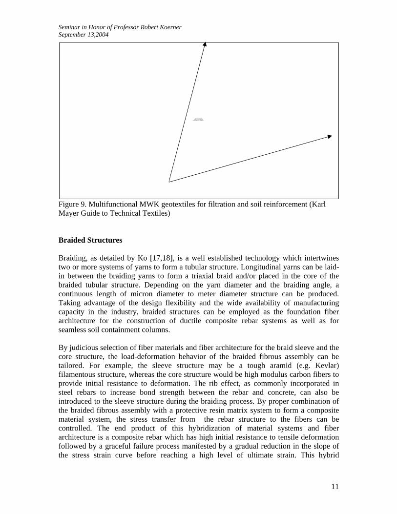
Since MWK fabrics possess a high level of tensile strength due to their noncrimped nature (and tear resistance as a result of the bias reinforcement and stitching yarn integration), they can be engineered for a wide range of geotechnical applications (including filtration and soil reinforcement) as shown in Figure 9.

Seminar in Honor of Professor Robert Koerner September 13,2004
10
Figure 8a. Multiaxial warp knit with four layers (0, 90, and ±�) of inserted yarns and (a) chain stitch or (b) tricot stitch.
Figure 8b. Multiaxial warp knit LIBA system
Seminar in Honor of Professor Robert Koerner September 13,2004
11
Figure 9. Multifunctional MWK geotextiles for filtration and soil reinforcement (Karl Mayer Guide to Technical Textiles) Braided Structures Braiding, as detailed by Ko [17,18], is a well established technology which intertwines two or more systems of yarns to form a tubular structure. Longitudinal yarns can be laid-in between the braiding yarns to form a triaxial braid and/or placed in the core of the braided tubular structure. Depending on the yarn diameter and the braiding angle, a continuous length of micron diameter to meter diameter structure can be produced. Taking advantage of the design flexibility and the wide availability of manufacturing capacity in the industry, braided structures can be employed as the foundation fiber architecture for the construction of ductile composite rebar systems as well as for seamless soil containment columns. By judicious selection of fiber materials and fiber architecture for the braid sleeve and the core structure, the load-deformation behavior of the braided fibrous assembly can be tailored. For example, the sleeve structure may be a tough aramid (e.g. Kevlar) filamentous structure, whereas the core structure would be high modulus carbon fibers to provide initial resistance to deformation. The rib effect, as commonly incorporated in steel rebars to increase bond strength between the rebar and concrete, can also be introduced to the sleeve structure during the braiding process. By proper combination of the braided fibrous assembly with a protective resin matrix system to form a composite material system, the stress transfer from the rebar structure to the fibers can be controlled. The end product of this hybridization of material systems and fiber architecture is a composite rebar which has high initial resistance to tensile deformation followed by a graceful failure process manifested by a gradual reduction in the slope of the stress strain curve before reaching a high level of ultimate strain. This hybrid
QuickTime™ and aGraphics decompressor
are needed to see this picture.

Seminar in Honor of Professor Robert Koerner September 13,2004
12
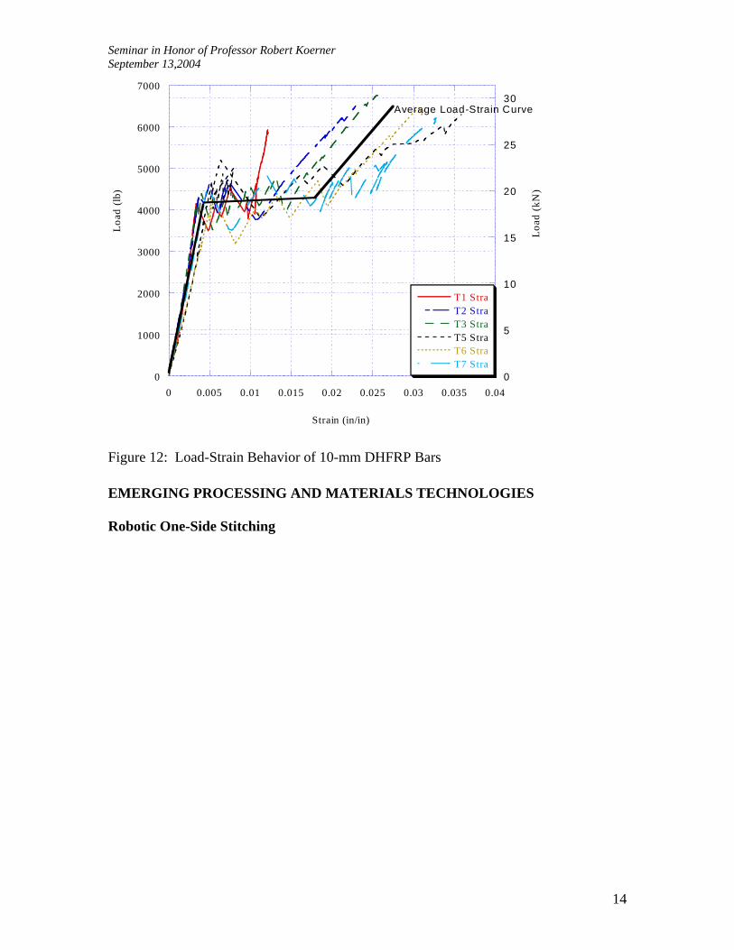
geometric and hybrid material effects can be realized by combining the braiding and the productive pultrusion process or the “Braidtrusion” process developed at Drexel with the participation of several civil engineering and materials engineering students, including Frank Hampton, a Koerner Fellow [19,20,21]. This unique manufacturing process can be used to develop a wide spectrum of products with various mechanical properties depending on the application. Also, the flexibility of the process allows for tailorability of specific mechanical properties including strength, stiffness, ductility, and surface geometry. As illustrated in Figure 10, the design methodology developed for Braidtrusion considers five tailorable levels of translation efficiency: fiber, yarn, twist, woven, and braid levels. Careful consideration of each material level results in an optimized structure. The process is especially attractive for hybrid composites using two or more yarn materials. A core of one material can be used as a mandrel while yarns of another material can be braided around the core. Depending on material selection and application, a wide variety of properties can be developed. The Braidtrusion process includes five zones of manufacturing as shown in Figure 11, including core formation, sleeve formation, consolidation, curing, and finished product. Various processing parameters including the braid angle, the fiber volume fraction, curing process, and the core and sleeve materials influence the mechanical properties of the finished composite. Four areas of tailorability were investigated using the Braidtrusion process: 1) tailoring of the composite modulus along the length using in-line change of fiber orientation; (2) traction tailoring by introduction of ribs for surface geometry; (3) co-braiding of hybrid materials and geometry for stress-strain property tailoring; and (4) combination of braiding and pultrusion to facilitate continuous and scalable manufacturing. The ductile rebar concept is illustrated with a case studies using the Braidtrusion process include the manufacturing and development of a ductile hybrid fiber-reinforced polymer bar (DHFRP) for reinforced concrete structures. [21,22]. The DHFRP bar, manufactured in sizes up to 10 mm, demonstrates three of the four tailoring parameters. The bars are a material hybrid of aramid fiber (Kevlar 49) and carbon fiber (Thornel P-55S). First, the tailoring of traction was done by integrating rib yarns into the bar surface geometry, thus producing a pultruded bar with non-uniform cross-section. Second, using the theory of similitude, the bars were manufactured in 3-mm, 5-mm and 10-mm diameter sizes. The scaling effects were studied from model to prototype sizes. Third, the DHFRP bars are designed to have a tri-linear stress-strain behavior with a yield point and an ultimate strength greater than yield. This pseudo-ductile behavior is caused by using both material and architecture hybrids. This stress-strain tailoring enables the development of a family of tri-linear stress-strain curves depending on processing parameters and material selection. Experimental verification of the properties of DHFRP are shown in Figure 12. With the demonstration of the ductile composite rebars having metal-like behavior, steel rebar design code may be used for this new class of non-corrosive composite rebars thus opening up opportunities for a wide range of geotechnical reinforcement applications including walls, bulkheads, embankment and various concrete structures.

Seminar in Honor of Professor Robert Koerner September 13,2004
13
Core Effect
Braid Angle Effect
Crimp Effect
Yarn TwistEffect
Fiber Intrinsic Property Effect
β
φ
θ
Material and Fiber Level
Yarn and Twist Level
Braid and Composite Level
Core Effect
Braid Angle Effect
Crimp Effect
Yarn TwistEffect
Fiber Intrinsic Property Effect
β
φ
θ
Material and Fiber Level
Yarn and Twist Level
Braid and Composite Level
Figure 10: Design Methodology of the Braided Composite Structure
Figure 11: Schematics of the Braidtrusion Process for Composite Rebar Manufacturing
Seminar in Honor of Professor Robert Koerner September 13,2004
14
0
1000
2000
3000
4000
5000
6000
7000
0
5
10
15
20
25
30
0 0.005 0.01 0.015 0.02 0.025 0.03 0.035 0.04
T1 StraT2 StraT3 StraT5 StraT6 StraT7 Stra
Load
(lb
)
Strain (in/in)
Load
(kN
)
Average Load-Strain Curve
Figure 12: Load-Strain Behavior of 10-mm DHFRP Bars EMERGING PROCESSING AND MATERIALS TECHNOLOGIES Robotic One-Side Stitching
Seminar in Honor of Professor Robert Koerner September 13,2004
15
Figure 14 illustrates the formation of a chain stitch using two needles coming from the same (top) side of the fabric. ROSS is recognized as an important emerging technology in the advanced composite performing and protective textile industry; because of the programmable robot arm and single-side access to the fabric, the ROSS can join very complex shapeed structures over a large surface area. It can also provide a means to place local, through- the-thickness reinforcement for composite structures. Considering the unique capability of one sided stitching, Boeing has purchased a similar ROSS unit for their composite wing manufacturing program (wherein stiffeners are stitched to the wing skin for a 737 wing structure). The ROSS at Drexel is one of only two systems in the US. Considering the versatility of the stitching head, it is quite conceivable that a field robot could be equipped with an OSS unit to perform automatic field sewing of geotextiles.
Figure 14. The formation of chain stitch by the OSS.
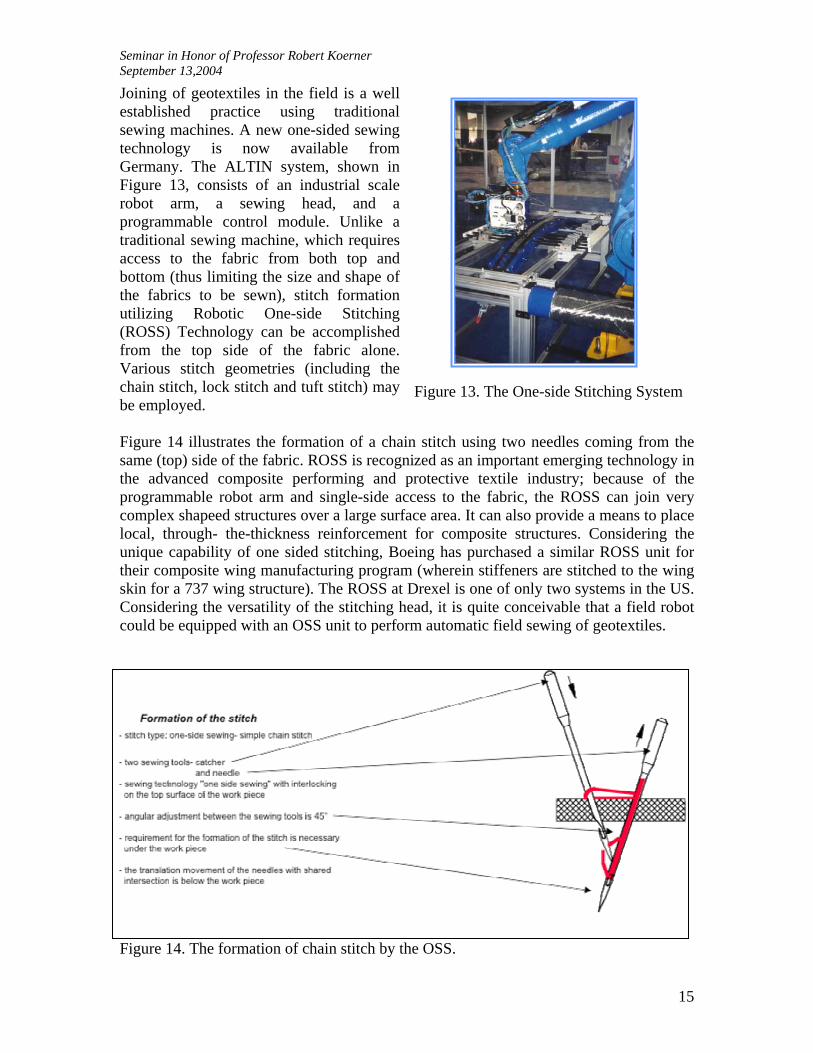
Joining of geotextiles in the field is a well established practice using traditional sewing machines. A new one-sided sewing technology is now available from Germany. The ALTIN system, shown in Figure 13, consists of an industrial scale robot arm, a sewing head, and a programmable control module. Unlike a traditional sewing machine, which requires access to the fabric from both top and bottom (thus limiting the size and shape of the fabrics to be sewn), stitch formation utilizing Robotic One-side Stitching (ROSS) Technology can be accomplished from the top side of the fabric alone. Various stitch geometries (including the chain stitch, lock stitch and tuft stitch) may be employed.
Figure 13. The One-side Stitching System
Seminar in Honor of Professor Robert Koerner September 13,2004
16
Nanofiber Technology When looking to future generations of geotextiles, an examination of the role of nanotechnology in the functional enhancement of geotextiles is in order. By reducing fiber diameter down to the nanoscale, an enormous increase in specific surface area to the level of 1000 m2/g is possible. This reduction in dimension and increase in surface area greatly affects the chemical/biological reactivity and electroactivity of polymeric fibers. Because of the extreme fineness of the fibers (as illustrated qualitatively in Figures 15-17) there is an overall impact on the geometric and thus the performance properties of the fabric. There is an explosive growth in worldwide research efforts recognizing the potential nanoeffect that will be created when fibers are reduced to nanoscale [23]. Briefly, nanofiber technology is the synthesis, processing, manufacturing and application of fibers in the nanoscale. By definition, nanofibers are fibers with diameter equal to or less than 100 nm. Due to product requirements and manufacturing capability limitations, some industries tend to consider any fibers of submicron diameter to be “nanofibers”. The rapid growth of nanofiber technology in recent years can be attributed to the rediscovery of electrostatic spinning (or electrospinning) technology originally developed in the 1930s [24]. This technique has been used to produce high-performance filters [25,26], wearable electronics [27] and scaffolds for tissue engineering [28] that utilize the high surface area unique to these fibers. A schematic drawing of the electrospinning process is shown in Figure 15a, where a high electric field is generated in a polymer fluid contained in a glass syringe with a capillary tip and a metallic collection screen. When the voltage reaches a critical value, the electric field overcomes the surface tension of the deformed drop of the suspended polymer solution formed on the tip of the syringe and a jet of ultra-fine fibers is produced. The electrically-charged jet undergoes a series of electrically-induced bending instabilities during its passage to the collection screen that results in the hyper-stretching of the jet. This stretching process is accompanied by the rapid evaporation of the solvent molecules, which reduces the diameter of the jet in a cone-shaped radius. The dry fibers are accumulated on the surface of the collection screen, resulting in a non-woven mesh of nanometer to micron-diameter fibers. The process can be adjusted to control fiber diameter by varying the electric field strength and polymer solution concentration, while the duration of electrospinning controls the thickness of the fiber deposition. Nanofibers in linear yarn or planar nonwoven mat form can be produced by proper control of the electrodes.

Seminar in Honor of Professor Robert Koerner September 13,2004
17
Figure 15a. Schematic Drawing of the Electrospinning Process
Figure 15b. Electrospun nanofiber membrane
The enormous specific surface area of these nanofibrous assemblies may make them excellent candidates for gas collection layers in landfill cover systems. By controlling the porosity and proper selection of the polymer system, barrier membranes may be produced having selective permeable characteristics similar to that used in chem./bio protective barriers [29].
SUMMARY AND CONCLUSIONS The pioneering effort of Professor Koerner in the new field of geotextiles has established a firm knowledge base for the engineering design and creative use of textiles for geotechnical applications. This has led to enormous economic growth for the chemical, fiber, textile and geotechnical industry complex around the world. Although there is a large family of textile structures available for geotechnical applications, a fundamental understanding of the dynamic interaction between textile structure and the geotechnical environment is essential for proper design and selection of geotextiles for a specific application. To provide a basis for assessment of the various fiber architectures for geotextiles, the geometric and performance properties of various textile structures have been shown in terms of performance maps. Specific examples of textile technologies suitable for linear and planar multiaxial reinforcement have been presented along with the introduction of a new robotic based sewing technology. This paper is concluded by connecting geotextiles with the emerging nanofiber technology which may play a useful role in nanocomposite reinforcement, hydraulic, geoenvironmental and energy mining applications (as outlined by Professor Koerner in his thought provoking Thirty-second Terzaghi Lecture almost eight years ago) [30].
V
Meteringpump
High voltagepower supply
+
Syringe(Polymer solution)
Taylor coneStability region
Instability region
Target/collectionplate
Nanofibers 1micron
Seminar in Honor of Professor Robert Koerner September 13,2004
18
REFERENCES 1. Koerner, R.M., and Ko, F.K., Laboratory Studies of Long Term Drainage Capability of
Geotextiles, Proceedings, Part I. Second International Congress on Geotextiles, Las Vegas, August, 1982
2. Kaswell, E. R, Handbook of Industrial Textile, New York, West Point Pepperell, 1963 3. George B. Haven., Mechanical Fabrics, John Wiley & Sons, 1932 4. Journal of Industrial Fabrics, Vol.1, Number 1,Summer 1982, IFAI 5. Chou, T.W. and Ko, F.K., Textile Structural Composites, Elsevier, 1989 6. Koerner, R.M. and Welsh, J.P., Construction and Geotechnical Engineering Using
Synthetic Fabrics, John Wiley and Sons, New York, 1980. 7. Rankilor, P.R., Membranes in Ground Engineering, John Wiley and Sons, New York,
1981. 8. Dierickx, W; The influence of Filter Materials and their Use as Wrapping Around
Agricultural Drains, C.R. Coll. Int. Sols Textiles, Paris, 1977, Vol.2,pp.225-229. 9. Hoffman,G.L. and Malasheskie, G., Laboratory Evaluation of Materials and Design
Characteristics of PennDOT Underdrain System, Transportation Res. Rec. 675, Natl. Acad. Sci., Washington, DC, 1978, pp.32-43
10. Koerner, R.M., Gugliemetti, J.L. and Rosenfarb, J.L., On the Permeability Testing of Fabrics and Fabric/Soil Systems, Proc. 8th Tech. Symp. on Nonwovens – Innovative Fabrics for the Future, INDA, Kissimmee, Florida, March 19-21, 1980, pp.143-154
11. Ko, F. K., Bruner, J., Pastore, A. & Scardino, F. 1980, Development of Multi-Bar Weft Insertion Warp Knit Fabric for Industrial Applications, ASME Paper No. 90-TEXT-7, October.
12. Ko, F. K., Krauland, K. & Scardino, F. 1982, Weft Insertion Warp Knit for Hybrid Composites, Proceedings of the Fourth International Conference on Composites.
13. Ko, F. K., Fang, P. & Pastore, C. 1985, Multilayer Multidirectional Warp Knit Fabrics for Industrial Applications, J. Industrial Fabrics, Vol. 4, No. 2, 1985.
14. Ko, F.K., Pastore, C.M., Yang, J.M. & Chou, T.W. 1986. Structure and Properties of Multidirectional Warp Knit Fabric Reinforced Composites, in Composites '86: Recent Advances in Japan and the United States, Kawata, K., Umekawa, s. and Kobayashi, A., eds. Proceedings, Japan
15. Ko, F.K. & Kutz, J. 1988b. Multiaxial Warp Knit for Advanced Composites, Pro-ceedings of the Fourth Annual Conference on Advanced Composites, ASM International, pp.377-384
16. Du, G.W. & Ko, F.K. 1992. Analysis of Multiaxial Warp Knitted Preforms for Composite Reinforcement, Proceedings of Textile Composites in Building Construction Second International Symposium, Lyon, France, June 23-25.
17. Ko, F. K. 1988a. Braiding, Engineering Materials Handbook, Vol. 1, Composites, Reinhart, T.J. Editor, ASM International, Metal Park, OH, pp.519-528.and “Braiding” in Vol.21.ASM Handbook, Composites,2001,pp69-77
18. Ko, F.K., Pastore, C.M. and Head, A.A., Atkins and Pearce Handbook of Industrial Braiding, Drexel University, 1989
19. Somboosong, W., development of Ductile Hybrid Fiber Reinforced Polymer (DHFRP) Reinforcement for Concrete Structures, 1977, PhD Thesis, Drexel University

Seminar in Honor of Professor Robert Koerner September 13,2004
19
20. Lam, H.L., Composite Manufacturing with the Braidtrusion Process, 2001, MS Thesis, Drexel University
21.Hampton, F.P., Cyclic Behavior, Development, and Characteristics of a Ductile Hybrid Fiber Reinforced Polymer (DHFRP) Reinforced Concrete Members, 2004, PhD Thesis, Drexel University
22. Hampton, F. P. , Harry, H. G., and Ko, F. K., ., Low-Cycle Fatigue Strength Of A Ductile Hybrid Fiber Reinforced Polymer Bar For Earthquake Resistant Concrete Structures, Proceedings, ICCM 14, San Diego, CA., Paper ID: 1295, July 14-18, 2004
23. Ko, F.K., Nanofiber Technology: Bridging the Gap between Nano and Macro World”, in NATO ASI on Nanoengineeered Nanofibrous Materials, 2003, Anatalia, Turkey, Kluwer Academic Publishers
24. Formhals, A., US Patent # 1,975,504, 1934. 25. Doshi, J., D. Reneker, H., J. Electrost. 1995, 35, 151 26. Gibson, P. W., Schreuder-Gibson, H. L., Riven, D., AIChE J. 1999, 45, 190 27. Ko, F.K., El-Aufy, A., Lam, H.L., and MacDiarmid, A.G., “Electrostatically
Generated Nanofibers for Wearable Electronics”, in Wearable Electronics, Edited by X.M. Tao, Woodhead, 2004
28. Ko, F. K., Laurencin, C. T., Borden, M. D., Reneker, D. H., The Dynamics of cell-fiber architecture interaction, in: Proceedings, Annual Meeting, Biomaterials Research Society, San Diego, April 1998.
29. Ko, F. K., Yang, H.J., Argawal, R., and Katz, H., Electrospinning of Improved CB Protective Fibrous Materials , Proceedings, Techtextil Atlanta, March 30-31, 2004
30. Koerner, R.M., Emerging and Future Developments of Selected geosynthetic Applications, J. of geotechnical and Geoenvironmental Engineering, April 2000, pp291-306