seminar report on axial field electrical machine
TRANSCRIPT

CONTENTS
1. Introduction 1
2. Classification Of Axial-Field Machines 2
3. Differences Between Axial-Field And Conventional Machines 3
4. Main Configurations Of Axial-Field Machines 4
4.1 Faraday Disk
4.2 Printed Circuit Board Motors
4.3 Axial-Field Electromagnetic Differential Induction Motor
4.4 Axial-Field Machines With Yokeless Armature Core
4.5 Single-Phase Axial-Field And Induction Motors
4.6 Disc-Armature D.C. Motor
4.7 Multi-Stage Axial-Field Permanent-Magnet With Water-Cooled
4.8 Double-Disc Alternator With A.C.-Side Excitation
4.9 Axial Flux Interior Permanent Magnet Synchronous Motor
4.10 Torus Machine
4.10.1 Properties Of The Torus Machine
4.10.2 Modes Of Operation Of The Torus Machine
4.10.2.1 D.C. Generator
4.10.2.2 A.C. Generator
4.10.2.3 Brushless D.C. Motor
5. Applications Of The Axial-Field Machines 15
5.1 Auxiliary Power Units
5.2 Wind-Power Generator
5.3 Electric Scooter Drive
5.4 Water-Cooled Ev Drive

5.5 High Speed Generator Driven By A Gas Turbine
5.6 Adjustable-Speed Pump Drive
5.7 Coreless-Winding Axial-Field Permanent-Magnet Generator
6. Conclusions 17
7. References 18

INTRODUCTION
An electrical machine is an electromagnetic energy conversion device. It translates its input electrical power into an output mechanical power. Electrical machines have been available and working for nearly a century. During this period many extensive efforts have been made by researchers worldwide to develop and improve design, configuration and performance of electrical machines.
Nowadays, electrical machines are found in various physical topologies. They may be categorized according to their conductor geometry and field orientation as :1. Radial-field machine, where the conductor is axial and the airgap flux is radial.2. Axial-field machine, where the conductor is radial and the airgap flux is axial.3. Linear machine, where the mutually perpendicular flux and the conductors are arranged along a linear path.The history of electrical machines shows that the earliest machines were of the axial-field type. Based on the principle of electromagnetic induction, Faraday invented the Faraday disk in 1832, which is also called the homopolar machine. Because of the strong magnetic force existing between the stator and the rotor, these machines were soon replaced by radial-field machines. These radial-field machines have been and are still used to a large extent. As mentioned above, one drawback of the axial-field design is the strong magnetic force between its stator and rotor. This problem may be alleviated by using a sandwich configuration with a stator placed between two rotors or a rotor sandwiched between two stators. A study of axial-field machines reveals that high electrical power to weight ratios have been achieved. There is reason to believe that axial-field machines will be used in the future in a large number of applications where their special features offer distinct advantages. Some potential applications of the axial-field machines include car heater blower, radiator cooling fan, auxiliary power unit, wind-power generator, electric vehicle, high speed generator driven by a gas turbine, adjustable-speed pump drive, lawnmower motor, and others.
This report examines first the overall construction, development, and principle of operation of axial-field machines, then compares the different configurations, steady state characteristics and applications of various axial-field machines.
Figure 1
1

CLASSIFICATION OF AXIAL-FIELD MACHINES
In theory, each type of radial-field machine will have an analogous axial-field machine. Therefore, an axial-field machine can operate as a d.c. machine as well as an a.c. synchronous or induction machine. Figure 2 shows the topology of the magnetic circuit of the axial-field machine.
These machines can be constructed in one of the following ways in correspondence with the design of the magnetic circuit:
1. Single stator and single rotor (one airgap), as shown in Figure 2(a).
2. Central-stator machine (double airgaps), as shown in Figure 2(b).
Figure 2. Topology of the magnetic circuit of axial flux machine (Φ is the flux).
3. Central-rotor machine (double airgaps), as shown in Figure 2(c).
4. Multi-disc machine (multiple airgaps).
Machines constructed using a single stator/rotor experience a strong magnetic pull between the stator and rotor and therefore, the sandwich configuration appears much more viable. Of the two types of sandwich construction available, the central-stator machine produces more torque per length of stator conductor, since both the working surfaces of the stator core are used. In axial-field machines, the electromagnetic torque is a function of the machine outer diameter. The multi-stage arrangement is suited to overcome the restriction on the machine diameter and to meet the torque required at the machine shaft.
2

DIFFERENCES BETWEEN AXIAL-FIELD AND CONVENTIONAL MACHINES
Axial-field machines differ from conventional machines in the following:
1. The airgap flux is axial in direction and the active current carrying conductors are radially positioned.
2. The stator and the rotor cores are of the disc type.
3. A higher percentage of the stator winding produces torque. This is due to the fact that the stator winding is wound in a toroidal configuration. Thus, the two working surfaces of the core are both active for the electromechanical energy conversion such as in the Torus machine.
4. The two rotating discs (in the central-stator machine) act naturally as fans, thereby removing heat produced by copper and iron losses. This can be accomplished by means of holes positioned near the mechanical shaft so that the air flows radially through the machine airgaps. This machine configuration, therefore, permits an exploitation of active materials than in conventional machines.
5. Axial-field machines can be designed to possess high power to weight ratios with more saving in the core material especially if permanent magnets are used. They have also a larger diameter to length ratio.
6. Floor space required for manufacturing and assembly line is significantly reduced for the axial-field machine.
7. The short axial length of the axial-field machine results in a larger diameter than that of the radial-field machine and hence a higher inertia for the same power rating. This limits their application to systems requiring slow response.
Figure 3
3

MAIN CONFIGURATIONS OF AXIAL-FIELD MACHINES
1. Faraday Disk
Based on the principle of electromagnetic induction, Faraday (1832) illustrated that if a copper disk is rotated in an axially magnetic field, with sliding contact and brushes mounted at the rim and at the center of the disk, a voltage will be present at the brushes. Such a machine is commonly known as the Faraday disk or the homopolar generator and is shown in Figure 4. The device is also capable of operating as a motor.
Figure 4
2. Printed Circuit Board Motors
In 1958, F. H. Raymond and J. Henry-Baudot invented the first printed-circuit-board (PCB) d.c. motor. The armature had a disk shape. The motor is lighter and shorter than a conventional type but slightly larger in diameter. It has a short time constant which results in a very fast response and low rotor inertia. These advantages derive mainly from the fact that the armature has no iron in it.The PCB armature (rotor) has conductors that are stamped from a sheet of copper, welded together and placed on a disc. The conductor segments are then joined with a commutator at the center of the disk. The disk armature is located between two sets of permanent magnets mounted on ferromagnetic end plates.The magnets are circular in shape with magnet faces parallel to the printed armature. This arrangement provides axial flux through the armature. When current from a supply is passed through the armature conductors, they generate a field, which interacts with the permanent-magnet field to produce the torque needed for the armature. The PCB motor's special geometry, high power to weight ratio, and very high pulse torque, have led to their use in a variety of applications. Typical applications of PCB motors are in machine tools, computer peripheral equipment, ultra-violet recorder drivers, large control valves, etc…
4

3. Axial-Field Electromagnetic Differential Induction Motor
The basic layout of this type of machine comprises a single stator and two squirrel-cage rotors as shown in Figure 5. These rotors are mounted on two individual shafts and may rotate independently. The two surfaces of the stator core and the rotors have slots. The coils of the stator winding are placed in slots and wound in a toroidal fashion around the stator core. Both rotors carry a squirrel-cage winding. Since the excitation of the machine is from the stator winding currents, the airgaps must be reduced as much as possible in order to produce adequate airgap flux density. The machine has been used to drive the wheels of an electric vehicle by performing the function of both the engine and the differential.
Figure 5. Single converter-fed motor having one stator and two rotors
4. Axial-Field Machines with Yokeless Armature Core
The basic construction of this machine is that its armature is sandwiched between two rotor cores. The armature consists of a number of teeth; each is made of a packet of laminations. The laminated teeth are held together in position by two endplates where the armature winding is located (see Figure 6).
Figure 6
5

Note the absence of the yoke in the armature core. As a result, a considerable saving in the core material and a significant increase in the power/weight ratio of the machine are achieved. One way to construct the stator is to insert the teeth laminations into one endplate. The stator winding is then wound in place before the second endplate is placed in position on to the other end of the teeth lamination. The side view lamination of the armature core is shown in Figure 7.
Figure 7
5. Single-Phase Axial-Field Induction Motors
Single-phase axial-field induction motors may have distinct advantages in the field of small power domestic applications such as fans, pumps, etc… Firstly, the flat shape is a desirable configuration for such applications. Secondly, the rotor may be integrated with the rotating part of mechanical load. The axial force between the rotor and the stator is not so severe in the small power range and therefore, a thrust bearing can withstand it.
6. Disc-Armature D.C. Motor
This is an axial airgap machine with a permanent-magnet field system. The permanent-magnets are fixed to mild steel endplates by epoxy resin adhesive. The armature consists of two double layer windings. The active conductors running radially so that the complete armature is disc shaped. The coil ends are connected to the commutator and epoxy resin is added to give the whole armature rigidity. This motor can have two different types of design. In the first design (see Figure 8), the armature is free from iron, the windings being encapsulated in epoxy resin. As a result, all losses due to hysteresis or eddy currents are eliminated. However, with the addition of running clearance on either side of the disc, this leads to a large airgap. As any reduction in the airgap length would reduce the magnet length also, it was decided to incorporate the flux return ring in the armature for the second type of design. With this new arrangement (see Figure 9), the inherent high efficiency of the first design has been sacrificed. Eddy-current and hysteresis losses have been introduced into the armature and a thrust bearing is now unavoidable between rotor and stator. The disc-armature d.c. motors are basically similar to printed-circuit- board (PCB) motors. The difference is in the shape of the permanent-magnet and in the armature design. The shape of the pole
6

segments in disc-armature d.c. motor gave a more uniform airgap flux density than the circular pole in PCB. Moreover, the armature design of the disc-armature motor allows it to sustain much larger overload currents, which leads to a much greater reliability.
Figure 8
Figure 9. Disc armature motor with a flux return ring.
7. Multi-Stage A.F. Permanent-Magnet with Water-Cooled Ironless Stator
For some applications, lightness and long-term overload capability are of crucial significance. A totally enclosed construction of the motor is required where the machine must operate in a hostile environment. To meet such conditions, direct cooling of the stator winding must be used and may be achieved using an ironless stator. The space normally occupied by the core becomes a water duct, which removes heat directly from the stator winding. In principle, the winding coils in an ironless stator may have a trapezoidal shape, but these have significant end-winding length. Much higher values of torque per unit I 2 R loss are achieved by means of winding coils of rhomboidal shape as illustrated in Figure 10.
7

Figure 10. Rhomboidal coil shape for machine with ironless stator.
Optimum values of inclination angle α lie between 60 to 70 degrees and the ratio of the outer
radius Ro to the inner radius Ri is between 1.45 and 1.65. Multi-stage designs provide a solution for higher ratings when there are limits on acceptable machine diameter. In a multi-stage axial flux machine, if n is the number of stages, then the machine has n stator windings
and (n+1) rotor discs. The (n+1) rotors share a common mechanical shaft whereas the
terminals of the three-phase windings may be connected either in series or in parallel. A two-stage arrangement of the machine is shown in Figure 11.
Figure 11. Cross section of two-stage A.F. permanent magnet machine with ironless watercooled stator winding
8

8. Double-Disc Alternator with A.C.-Side Excitation
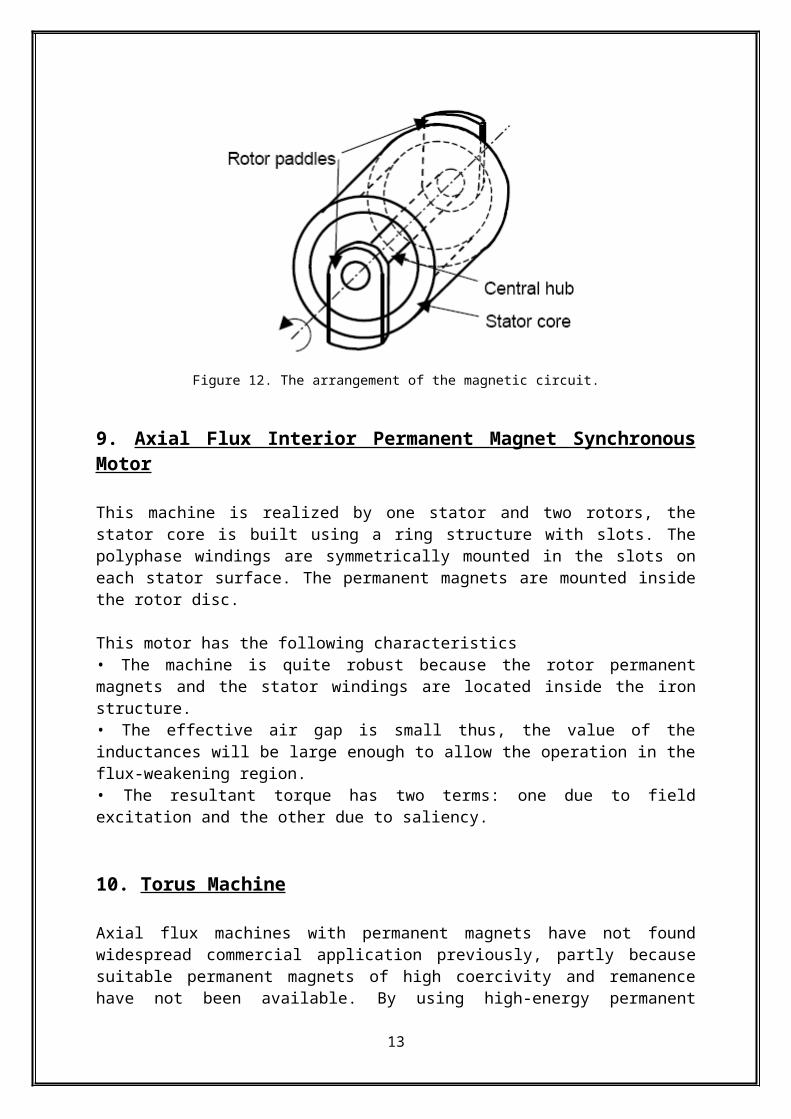
The rotor of this machine consists of a central hub interconnecting two rotor "paddles" which are circumferentially displaced with respect to each other by one pole pitch as shown in Figure 12.The stator core is a strip-wound laminated cylinder concentric with the rotor hub and located between the paddles. The field coil surrounds the hub but is separate from it and stationary. “The path for the main flux is axially along the hub, radially along one paddle and axially across the air gap into the stator core; dividing in the core, it passes circumferentially in both directions through one pole pitch, then axially across the second air gap into the second paddle, radially through the paddle and completes at the hub”. This arrangement produces directly a brushless machine with a rotating robust steel assembly.
Figure 12. The arrangement of the magnetic circuit.
9. Axial Flux Interior Permanent Magnet Synchronous Motor
This machine is realized by one stator and two rotors, the stator core is built using a ring structure with slots. The polyphase windings are symmetrically mounted in the slots on each stator surface. The permanent magnets are mounted inside the rotor disc.
This motor has the following characteristics• The machine is quite robust because the rotor permanent magnets and the stator windings are located inside the iron structure.• The effective air gap is small thus, the value of the inductances will be large enough to allow the operation in the flux-weakening region.• The resultant torque has two terms: one due to field excitation and the other due to saliency.
10. Torus Machine
Axial flux machines with permanent magnets have not found widespread commercial application previously, partly because suitable permanent magnets of high coercivity and remanence have not been available. By using high-energy permanent magnets such as
9

Neodymium-Iron-Boron (Nd-Fe-B), high values of the flux density in the airgap can be obtained even with relatively large airgap length. Sintered Nd-Fe-B magnets have a remanence, Br, in excess of 1T, recoil permeability approximately equal to that of air, and a coercivity of about 800A/mm. This fact has opened up application opportunities for axial-field machines. Such a machine allows the arrangement of a slotless-designed stator winding, which has the advantage of relatively short-end winding, resulting in low copper losses and consequently, increased efficiency.
Figure 13. Torus machine cross-section.
Axial flux machines with permanent magnets have not found widespread commercial application previously, partly because suitable permanent magnets of high coercivity and remanence have not been available. By using high-energy permanent magnets such as Neodymium-Iron-Boron (Nd-Fe-B), high values of the flux density in the airgap can be obtained even with relatively large airgap length. Sintered Nd-Fe-B magnets have a remanence, Br, in excess of 1T, recoil permeability approximately equal to that of air, and a coercivity of about 800A/mm. This fact has opened up application opportunities for axial-field machines. Such a machine allows the arrangement of a slotless-designed stator winding, which has the advantage of relatively short-end winding, resulting in low copper losses and consequently, increased efficiency.
In UMIST (University of Manchester Institute of Science and Technology) several 2.5 kW axial-field, slotless, toroidal-stator, permanent-magnet machines have been built and tested and have demonstrated all aspects of the steady-state capability and performance in the
10

generating and motoring modes. This type of configuration was called Torus. The name Torus was proposed by Spooner and Chalmers, to indicate the toroidal nature of both the stator winding and the stator core. Torus brings further improvements over earlier designs, because it employs comparatively new magnetic material (Nd-Fe-B) that has the necessary remanence, together with a coercivity, that permits a slotless winding to be used. Torus is an axially compact electrical machine suitable for the development of compact integrated designs. The basic layout is shown in Figure 13, the machine has similarities with several other configurations proposed in recent years including the permanent-magnet axial-field machine investigated by and slotless-disc alternator.
For a machine to deliver high power from a small space, it must have:
(a) High magnetic and electric loadings.(b) Intensive cooling to remove the losses.(c) Low impedance to avoid pull-out.
The use of the sintered Neodymium-Iron-Boron magnets enables a high magnetic loading to be achieved. The rotor discs act naturally as fans and so good cooling of the stator winding is ensured even with a high electric loading. The values of the phase self and mutual inductances are low because the magnetic gap is large and the slot leakage is absent. Moreover, with the high magnetic loading, the required emf could be generated using a small number of winding turns and so the inductance and the resistance are low.The core is a toroid wound from thin electrical steel strip; the quantity of steel used is quite small. It works at high flux density in the tangential direction but a rather low flux density axially. These features lead to low iron loss. The Torus machine is a double-sided, axial-field, disc-type, permanent-magnet, brushless machine. It has a simple toroidal, strip-wound stator core that carries a slotless toroidal winding which may have any chosen number of phases, as illustrated in Figure 14.
Figure 14. Toroidal stator with 11-phase winding.
The experimental 6-pole machine is shown in Figure 15. The a.c. output of the machine is fed through rectifiers that are mounted on the stator casing. It can be seen that the casing forms a well-ventilated heat sink for mounting the electronic components. The machine has been designed to provide a flat-topped emf wave to avoid excessive ripple in the output voltage. A large number of phases raises the frequency of the output ripple so that filtering can be performed with a small passive component. For brushless d.c. motor operation, additional electronic components are required which may be fixed to the casing. In the stator the copper losses have two component, loss due to the flow of current in the windings and eddy current loss due to the main airgap field passing through the conductors. The copper losses are
11

removed by conduction into the iron core and by the heat transfer to the air flowing between the stator and the rotor.
Figure 15. Experimental 2.5 kW Torus machine with outer rotor disk removed, mounted on a 4 kW induction motor.
The rotor comprises two discs carrying six axially polarized magnets, as illustrated in Figure 16.
Figure 16. Six-pole inner rotor for 2.5 kW experimental machine.
Typical flux paths are indicated in Figure 17. The rotor discs may be mounted directly on the shaft of the coupled machine, eliminating the need for a coupling and separate bearings. Moreover, the flywheel and ventilation fan may be eliminated. The rotor suffers no significant losses because the Torus machine is excited by permanent magnets.Each phase in the armature consists of a pair of coils wound on the core at positions separated by 180 mechanical degrees as shown in Figure 18. The two coils are connected in opposition so that no flux tends to pass around the core when current flows. Torus has a very small stator leakage and relatively small mutual inductances because of the slotless configuration and the large effective airgap compared to a conventional machine with slotted stator.
12

Figure 17. Principal flux paths (shown as dotted lines).
The active conductor lengths are the radial portions facing the magnets. The axially directed end-winding lengths are relatively short, yielding low resistance compared with the end-winding resistance of a normal machine. The slotless armature windings are also known as airgap windings.
Figure 18. Arrangement of a phase winding.
10.1 Properties of the Torus Machine
The salient feature of the Torus machine can be summarised as follows:1. Torus machines have short axial length and high power to weight ratio. The overall arrangement of Torus is compact and suitable for mechanical system integration.2. The slotless airgap winding gives low values of mutual and leakage inductances because the effective airgap is necessarily large and slot leakage is absent.3. Owing to the large effective airgap length, the magnets are less prone to demagnetisation.
13
4. Vibration, flux ripple and high-frequency rotor losses owing to stator slotting are eliminated.5. The absence of slots leads to a low-noise machine with negligible cogging torque.6. Saturation and iron losses of stator teeth are absent.
10.2 Modes of Operation of the Torus Machine
The machine may be operated as an a.c. generator or its output may be rectified for generating d.c. power. It may also operate as a motor via suitable switching circuits.
10.2.1 D.C. Generator
The Torus arrangement is well suited for use as a low-voltage d.c. generator with low voltage ripple. The a.c. output of the machine is fed through rectifiers, which may be mounted on the stator casing, which act as a well-ventilated heat sink. The magnet shape may be made close to the arc shape; as a result, the phase emf is a flat-topped wave. The magnitude of the ripple voltage appearing across the bridge rectifier depends on the machine number of phases and on the impedance of the load. For 11-phase, 6-pole machine, 3000 r.p.m. generator, the ripple frequency in the rectified d.c. output is 1650 Hz so that filtering can be easily performed. The ripple voltages may be filtered by means of a capacitor connected across the machine terminals.A permanent magnet is a constant excitation field system so that the output of an isolated permanent-magnet generator exhibits its natural voltage regulation characteristics. This may be overcome by several alternative methods :
1. Adjusting the drive speed to the generator.2. Designing the machine to have low series impedance. Since a slotless winding is used thus providing low values of phase self and mutual inductances because the magnetic gap is large and the slot leakage is absent.3. Adding a voltage regulator.4. Utilising magnetic saturation within the design so that on load, the armature reaction mmf simply reduces the degree of saturation.5. Adjusting the total induced emf by mechanically adjusting the angular displacement between the rotor disks.
10.2.2 A.C. Generator
Reduction of the harmonic content of the generated open circuit voltage in Torus generator is achieved by the shaping of the magnet thickness and relative displacement of the rotor disks by a small angle.
10.2.3 Brushless D.C. Motor
Any axial-field d.c. machine may be operated as a brushless d.c. motor in the same way as a cylindrical machine using a variable-frequency inverter to feed currents into the stator windings in synchronism with the rotor speed. The inverter is fired according to information obtained from the rotor position sensor and so, performs the same function as the brushes and the commutator in a d.c. motor. In these types of machines there is little scope for field weakening by the usual technique of phase advancing the stator currents.
14

APPLICATIONS OF THE AXIAL-FIELD MACHINES
Axial-field machines are particularly appropriate for the development of compact integrated designs owing to their disc-shape. Some potential applications of the axial- field machine include the following:
1. Auxiliary power units
Using the Torus configuration a number of auxiliary power units for military applications have been developed in association with Dornier GmbH.
2. Wind-power generator
The Torus generator can be direct coupled to a wind turbine allowing the elimination of the gearbox. This brings about reduced nacelle weight and noise, and improved reliability and efficiency. These considerations led to the proposed use of direct-coupled Torus generators for small-scale stand-alone generating systems in remote areas. 10 kW stand-alone wind/photovoltaic generating system prototypes have been constructed. Figure 18 shows the layout of a system that uses a wind turbine-driven permanent-magnet machine and a photovoltaic array as power generating units.
The principal features of the system are:1. The permanent-magnet wind generator is directly driven and has high torque to weight ratio and high efficiency.2. The double-input, single-output, d.c.-d.c. converter, combines the power generated by the wind and photovoltaic array with high efficiency.3. The d.c.-d.c. converter is used for charging a storage battery and supplying the user a.c. load via a voltage source inverter.
3. Electric scooter drive
An axial-field slotless permanent-magnet motor was used as motor-in-wheel drives for an electric vehicle to replace the 3HP two-stroke engine in a standard production scooter. The motor drive arrangement uses a microprocessor-controlled IGBT power converter, which is fed by a lead-acid battery. The motor was supplied from a 96 d.c. voltage via a microprocessor-controlled IGBT power electronic interface consisting of a bi-directional d.c.-d.c. converter and a current-regulated PWM inverter. The use of a bi-directional converter allows suitable control of both motoring and regenerative braking operations and also for on-board battery charging from the main supply.
4. Water-cooled EV drive
The arrangement with a water-cooled ironless stator is particularly suitable for direct-coupled wheel drives demanding high torque density. The motor construction could be totally enclosed to provide protection against the environment. A single-stage demonstrator machine was first developed and tested to prove the principle, and a two-stage machine was then designed for the application in an innovative city car. The power loss within the winding is
15

removed by assisted circulation of cooling water. This results in a relatively low over-temperature between the inlet and the outlet of the cooling duct.
5. High speed generator driven by a gas turbine
High speed enables a high power output to be obtained from a relatively small and lightweight machine, and allows the generator to be directly coupled to a gas-turbine engine. A prototype machine was driven at 60,000 r.p.m. by a small gas turbine engine. The generator is rated at 50 kVA. The machine could be used in an electric vehicle with suitable batteries as the electrical power source for the traction motors. Moreover, the machine could be used also as a small stand-alone generator set.
6. Adjustable-speed pump drive
The design and construction of a 3 Nm, 2800 r.p.m., slotless, axial-field machine prototype using ferrite permanent-magnets for application in adjustable speed pump drives, was reported by. This prototype drive possesses several advantages over the conventional three-phase induction motor such as, higher efficiency, compactness and lightness. Furthermore, it was shown that the manufacturing cost of the prototype, on a large scale, can be as low as that of an induction machine drive having the same power rating (for low power ratings).
7. Coreless-Winding A.F.P.M. Generator with power output at 400 Hz
In the design of power generation aboard aircraft and on ships, significant efforts have been made to ensure that lightness and compactness are as high as possible. A coreless-winding axial-field permanent-magnet generator with power output at 400 Hz, 3000 r.p.m. prototype has been designed and tested. Because of the use of an ironless winding placed in a high frequency rotating field, the eddy-current loss is a serious problem. This can be quite easily solved by using conductor arrangements based on Litz wires or multitier construction of the conductors.
16

CONCLUSIONS
Axial-field machines have been presented and discussed. They offer an alternative to the conventional radial-field machines. Their main advantages over the conventional machines are:
• They can be designed (using permanent magnets) to possess a higher power-to-weight ratio.• They have a larger diameter-to-length ratio.• They have a planar and adjustable airgap.• Their magnetic circuit topology can be easily varied so that many different types of axial field machines may be designed.
Axial-field electromagnetic differential induction motors are a promising solution for electrical cars because they can behave in the same way as an electro-magnetic differential supplied by a single set of inverters. The machines can have both higher efficiency and power density compared with two individual motors. Disc-type electrical machines with permanent-magnet excitation appear to be the best design in terms of compactness, suitability in shape, robustness, and superior electrical characteristics.
Because the axial-field machines can be designed to possess high power to weight ratio, they are more suitable for use in aircrafts. Their relatively flat shape makes them also suitable for ceiling-fan motors, radiator cooling fans, etc…The possibility of using an ironless rotor in the axial-field machine makes it appropriate for applications with fast response and low inertia. Moreover, the prospect of separating the stator and the rotor makes the axial-field machine design suitable for sealed and screened machines, such as domestic pump motors and wheel-directly-coupled motors for electric vehicles. Finally, reductions in the cost of high-field permanent magnets are expected to open-up several applications for the axial-field machines.
17

REFERENCES
# BOSE, B. 1986. Power Electronics and AC Drives. Englewood Cliffs, Prentice-Hall Inc., New Jersey.
# BAILEY, J., HAWSEY, R., DANIEL, D. and THOMAS, R. 1990. Design of a high power density, permanent magnet, axial gap d.c. motor. Southeastcon' 90, Proc. IEEE, 2 : 480-484.
# Evolution of Axial-Field Electrical Machines(By Abdullah Al-Badi, Adel Gastli, Hadj Bourdoucen and Joseph Jervase).
#Axial Field Electric Machines for Small-Scale Wind Generation (By Dr. Wen Soong, Dr. Nesimi Ertugrul, Kay Chien Tan,Yuanxing Pan)
# www.wikipedia.com
# Google images
18