sensorsim: a simulation framework for...
TRANSCRIPT
SensorSim: A Simulation Framework for Networks
Sensor
Sung Pa rk , A n d r e a s Savv ides , a n d M a n i B. S r i v a s t a v a
E lec t r i ca l E n g i n e e r i n g D e p a r t m e n t , U n i v e r s i t y of C a l i f o r n i a in Los Ange les
7702-B, B o e l t e r Hal l , Box 951594, Los Ange les , C A 90095-1594
E m a i h ~spark , a savv ide , m b s } @ e e . u c l a . e d u
Abstract-- T h e a d v e n t o f w i r e l e s s m i c r o s e n s o r s p r o m i s e s m a n y y e t u n r e a l i z e d b e n e f i t s . A n e t w o r k o f s u c h s e n s o r s or " s e n s o r n e t w o r k " i n t r o d u c e s a n e w s e t o f c h a l l e n g e s . B e s i d e s b e i n g ab l e t o c o m m u n i c a t e e f f ec t ive ly , s e n s o r n e t w o r k s have d e m a n d i n g s e n s i n g t a s k s . F i r s t , t h e y m u s t b e a w a r e o f t h e i r e n v i r o n m e n t a n d o f t e n t i m e s a r e r e q u i r e d t o a d a p t t o t h e i r s u r r o u n d i n g s . S e c o n d , t h e y m u s t c o o r d i n a t e a m o n g t h e m t o p e r f o r m a g r e a t e r g r o u p - s e n s i n g t a s k . I n t h i s c o n t e x t , t h e s t u d y o f s e n s o r n e t w o r k s has n u m e r o u s o t h e r a s p e c t s b e s i d e s c o m m u n i c a t i o n . T o c r e a t e a b e t t e r u n d e r s t a n d i n g of s e n s o r n e t w o r k s a n d t o fac i l i t a t e t h e d e v e l o p m e n t o f n e w p r o t o c o l s a n d a p p l i c a t i o n s , d e t a i l e d s i m u l a t i o n a n d p e r f o r - m a n c e e v a l u a t i o n t e c h n i q u e s n e e d t o b e d e v e l o p e d . I n t h i s p a p e r , w e i n t r o d u c e o u r o n g o i n g e f for t s in t h e d e v e l o p m e n t o f S e n s o r S i m , a s i m u l a t i o n f r a m e w o r k t h a t i n t r o d u c e s n e w m o d e l s a n d t e c h n i q u e s for t h e d e s i g n a n d "analysis o f s e n - sor n e t w o r k s . S e n s o r S i m i n h e r i t s t h e c o r e f e a t u r e s o f t rad i - t i o n a l e v e n t d r i v e n n e t w o r k s imu la to r s~ a n d b u i l d s u p n e w f e a t u r e s t h a t i n c l u d e a b i l i t y t o m o d e l p o w e r u s a g e in s en - sor n o d e s , h y b r i d s i m u l a t i o n t h a t a l l o w s t h e i n t e r a c t i o n o f real a n d s i m u l a t e d n o d e s , n e w c o m m u n i c a t i o n p r o t o c o l s a n d rea l t i m e u s e r i n t e r a c t i o n w i t h g r a p h i c a l d a t a d i sp l ay . A f t e r d i s c u s s i n g t h e d e t a i l s o f S e n s o r S i m , we p r o v i d e o u r c u r r e n t r e su l t s , t h a t d e m o n s t r a t e v a r i o u s c a p a b i l i t i e s o f S e n s o r S i m .
I . INTRODUCTION
The advancement of CMOS IC technology has con- tributed much to the introduction of wireless micro sen- sors. Based on micro-electromechanical systems (MEMS), a current micro sensor technology has abilities to perform various sensing tasks (seismic, infra red, sounds), signal processing, data collection, and wireless communication all in one single chip [1][4][5]. The advent of these tiny mi- cro sensors promises new set of possibilities in remote area monitoring. Sensor networks is becoming one of the most interesting research areas. Such networks can find applica- tions in many different settings. In industry for instance, a group of sensors may be used to closely monitor an auto- mated assembly line. They can sense machine malfunction, monitor process transition from one stage of the assembly line to the next and assist in quality control. In tactical environments, sensor networks can be deployed to monitor the activities of the enemy by detecting motion and track- ing targets. Other possible applications include monitoring of automobile traffic in urban areas, collecting of weather forecast data, and monitoring of endangered species and ecosystems.
The scope of the benefits that sensor networks will bring
This work was supported in part by DARPA under Grant F30W02- 99-1-0529
to our society is immeasurable. Nevertheless, sensor net- works pose a new set of challenges that need to be ad- dressed before such benefits can be realized. Many of the challenges in sensor networks arise from their deployment in hostile environments and the limited resources they must operate with. The following lists some of the main charac- teristics of sensor networks.
• Limited Resources: Sensor nodes can be deployed either by strategically placing them at specific locations or air dropping them in a remote a rea . Often times, these sen- sors are placed in a hostile environments where human oversight is very difficult if not impossible. The sensors are expected to work in such environments for long time with finite energy source in forms of battery. With lim- ited energy resources, the sensors must conserve power to prolong their lifetime. However, in order to conserve en- ergy, the CPU speed and the RF bandwidth of the sensors must be limited. For some applications such as military applications, the sensors should be small in size and have short transmission ranges to reduce the probability of de- tection. This size requirement imposes further constraints on the CPU speed, the size of the memory, the RF band- width and even the bat tery size. The sensor network must balance these different resources to increase the lifetime of the network, improve the quality of collected data, and decrease the communication latency. • Dynamic Network Topology: The sensor network topol- ogy is very dynamic. In other types of wireless networks (ad-hoc and cellular) the changes in topology are attributed to node movement. In ad-hoc networks old links are broken and new links are created as a node moves out of range of some nodes and enter the vicinity of other nodes. In cel- lular type networks, the topology changes as mobile nodes move about and handoff to different base stations. Unlike mobile nodes, sensor nodes are mostly stationary. Once positioned, sensor nodes will most likely remain station- ary for the duration of their lifetime. Although the nodes are static, the topology of a sensor network can constantly change. During periods of low activity, the network may enter a dormant state in which many nodes go to sleep to conserve energy. Also, nodes go out of service when the energy of the battery runs out or when a destructive event takes place. The rate at which the sensors go out of ser- vice can vary greatly from sensor to sensor even though all the sensors in the network started at the same time with the same amount of energy. This variation is caused by
104
random events (change of weather pa t te rn , enemy's move- ments, etc.. ) tha t t ranspi re in the sensor network. When a par t icular region of the sensor network experiences more events than other regions, the sensors located in tha t re- gion will be more active to handle those events. As a result , these active sensors will end up burning more of their en- ergy than idle sensors located in other region. As t ime progresses and the ba t te r ies are consumed, more and more sensors will go out of service. The sensor must be able to adap t to these changes to make the best use out of the remaining sensors. • Scalability: In a sensor network scalability is also a cru- cial factor. First, the coverage of a sensor node has a dual aspect, the sensing range and the communication radio range. The sensing range is usually smaller that the ra- dio range. Also, sensors have to operate in noisy environ- ments. To achieve good sensing resolution higher densities are required. Furthermore, since the nodes are susceptible to failure, a higher degree of redundancy is also a must. Second, to cover large areas networks of hundreds, and possibly thousands of nodes are needed to provide suffi- cient coverage. Thus in contrast to traditional Internet and ad-hoc based protocols, sensor network protocols need to sustain large number of nodes at high densities.
The numerous challenges make the study of real deployed sensor networks very difficult and financially infeasible. At the current stage of technology, a practical way to study sensor networks is through simulations that can provide a meaningful perspective into the behavior and performance of various algorithms. Our goal is to develop a detailed simulation framework, which can accurately model differ- ent micro sensors while providing a versatile testbed for new algorithms and protocols. In this paper, we present SensorSim, a simulation framework for sensor networks. SensorSim builds up on the core of a popular event driven simulator, ns-2 [7][8]. Our work extends ns-2 in a sensor network context by providing new power and communica- tion protocol models, support for hybrid simulations and new graphical user interface (GUI). This paper is organized as follows: In the next section we provide an overview of our system. Section Ill provides a detailed discussion of the power model for sensor nodes. Section IV explores hybrid simulation capabil i t ies and their integrat ion with a graph- ical user interface. In Section V, we present our current results. In section VI, we describe our vision for future work and section VI concludes this paper .
I I . OVV.RVI~.W
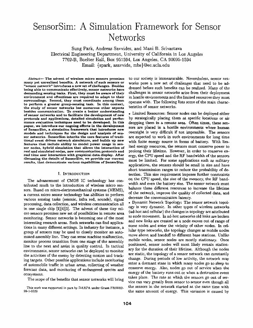
To bet ter unders tand the setup of a sensor network we first present a typical scenario t ha t may occur in the con- text of tact ical environment like the one shown in figure 1. In this scenario, a sensor network is deployed in a field to moni tor movements of enemy tanks which are considered as targets . The tank ' s movement is detected by the seismic sensors ( geophones ) on the sensor nodes and the ta rge t detect ion is p ropaga ted back to the control center where the information can be further analyzed by a central server and by human operators .
Fig. I. A Tactical Environment Scenario
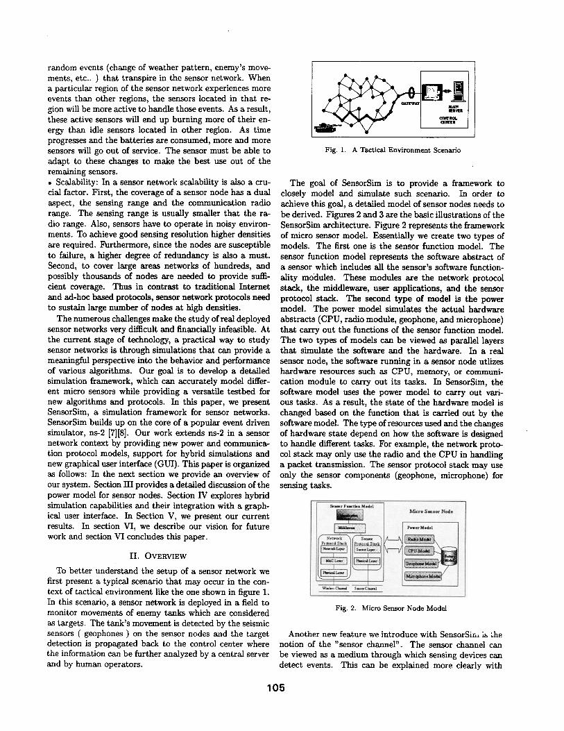
The goal of SensorSim is to provide a framework to closely model and s imulate such scenario. In order to achieve this goal, a detai led model of sensor nodes needs to be derived. Figures 2 and 3 are the basic i l lustrat ions of the SensorSim architecture. Figure 2 represents the framework of micro sensor model. Essential ly we create two types of models. The first one is the sensor function model. The sensor function model represents the software abs t rac t of a sensor which includes all the sensor 's software function- al i ty modules. These modules are the network protocol stack, the middleware, user applications, and the sensor protocol stack. The second type of model is the power model. The power model simulates the actual hardware abstracts (CPU, radio module, geophone, and microphone) that carry out the functions of the sensor function model. The two types of models can be viewed as parallel layers that simulate the software and the hardware. In a real sensor node, the software running in a sensor node utlizes hardware resources such as CPU, memory, or communi- cation module to carry out its tasks. In SensorSim, the software model uses the power model to carry out vari- ous tasks. As a result, the state of the hardware model is changed based on the function that is carried out by the software model. The type of resources used and the changes of hardware state depend on how the software is designed to handle different tasks. For example, the network proto- col stack may only use the radio and the CPU in handling a packet transmission. The sensor protocol stack may use only the sensor components (geophone, microphone) for sensing tasks.
Semsr Fw~lsn Medel
Wmtm Clmmd S~Ckm~l
~ c r o Smsor Node ~~ Pewer Medel
Fig. 2. Micro Sensor Node Model
Another new feature we introduce with SensorSin, is ~he notion of the "sensor channel". The sen~or channel can be viewed as a medium through which sensing devices can detect events. This can be explained more clearly with
105
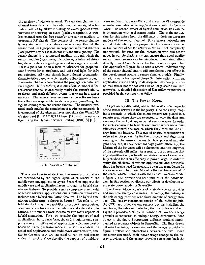
the analogy of wireless channel. The wireless channel is a channel through which the radio module can signal other radio modules by either initiating an event (packet trans- mission) or detecting an event (packet reception). A wire- less channel uses the free space(or air) as the medium to propagate RF signals. The concept of the sensor channel is very similar to the wireless channel except that all the sensor modules ( geophone, microphone, infra red detector ) are passive devices that do not initiate any signaling. The sensor channel is a compound medium through which the sensor modules ( geophone, microphone, or infra red detec- tor) detect external signals generated by targets or events. These signals can be in a form of vibration for geophone, sound waves for microphone, and infra red light for infra red detector. All these signals have different propagation characteristics based on which medium they travel through. The sensor channel characterizes the propagation details of such signals. In SensorSim, it is our effort to model differ- ent sensor channel to accurately model the sensor's ability to detect and track different events that occur in a sensor network. The sensor layer represents the software func- tions that are responsible for detecting and processing the signals coming from the sensor channel. The network pro- tocol stack enables the simulation of a wireless network. I t is composed of the physical layer modeling the WaveLAN wireless card [6], MAC 802.11 layer [12], and the network layer using the Dynamic Source Routing (DSR) [9] [10].
I
$1mldm~
Fig. 3. SensorSim Architecture
The network protocol stack and the sensor protocol stack are coordinated by the higher layers which consist of the middleware and application layers. SensorSim supports the middleware and application layers through its hybrid sim- ulation features. To provide a more comprehensive model of sensor network applications our simulation framework includes some hybrid simulation features. The hybrid sim- ulation architecture is shown in figure 3. We refer to hy- brid simulation as the capability to support input /output communication between our simulation and external appli- cations. Our current work focuses on two main aspects of hybrid simulation. First, we consider the support of real applications. In its basic form, the ns-2 simulator only sup- ports a very primitive set of applications which are mostly based on traffic generator models. SensorSim enables the use of real applications and middleware architectures, sim- ilar to the ones that are expected to run on real sensor nodes. In section V we describe the support of a middle-
ware architecture, SensorWare and in section VI we provide an initial evaluation of two applications targeted for Sensor- Ware. The second aspect of hybrid simulation we examine is interaction with real sensor nodes. The main motiva- tion for this arises from the difficulty in deriving accurate models of the sensor channel. Since sensor networks are still at their infancy, the properties of the sensor channel in the context of sensor networks are still not completely understood. By enabling the interaction with real sensor nodes in our simulations we can ensure that good quality sensor measurements can be introduced in our simulations directly from the real sensors. Furthermore, we expect that this approach will provide us with a better understanding of the sensor channel and it will complement our efforts in the development accurate sensor channel models. Finally, an additional advantage of SensorSim interaction with real applications is the ability to develop and test new protocols on real sensor nodes that can run on large scale simulated networks. A detailed discussion of SensorSim properties is provided in the sections that follow.
III. THE POWER MODEL
As previously discussed, one of the most crucial aspects of the sensor network is the longevity. One can easily imag- ine a scenario in which the micro sensors are placed in a remote area where they are expected to work for days and even months without any external energy source. In order for such scenario to be feasible each micro sensor node must efficiently control the rate at which they consume the en- ergy from the battery. This rate of energy consumption is referred as the power. As for the protocols and algorithms running on the sensors, no matter how powerful and ele- gant they are, if they don't manage power efficiently, the lifetime of the batteries will be shortened and the longevity of the network will suffer. As a result, it is imperative that any algorithms or protocols for sensor networks axe care- fully studied for their efficiency in power usage. In order to verify the efficiency of various applications and protocols, there has been a need for accurate power usage modeling for micro sensors. The Power Model is the hardware model of the sensor which interacts with the Sensor Function Model ( figure 2 ) to provide the true picture of the power us- age. In this section we discuss our efforts in developing an accurate power model in SensorSim.
The Power Model consists of a single energy provider and multiple energy consumers. Currently, the battery is the sole energy provider with finite amount of energy stor- age. The energy consumers consist of the radio module , the CPU, and other various sensory devices including the geophone, the infra red detector, the microphone and etc. Figure 4 provides a simple illustration of how the energy provider is connected to multiple energy consumers. Each object in the figure 4 represents different modules imple- mented as separate objects in SensorSim. The lines drawn between the energy consumers and the energy provider in figure 4 reflect the interactions between the two. Each consumer can notify their power usage change to the en- ergy provider, and the energy provider can report back the
106
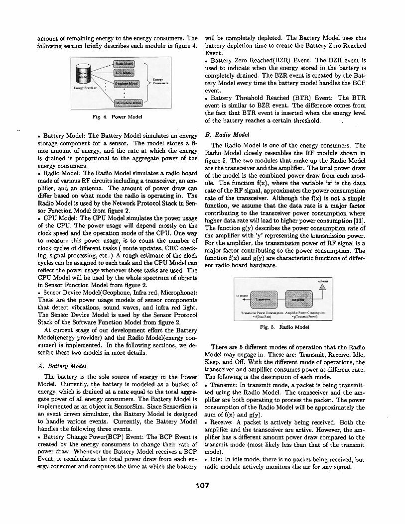
amount of remaining energy to the energy consumers. The following section briefly describes each module in figure 4.
ConJemm~
E . .
Fig. 4. Power Model
• Battery Model: The Battery Model simulates an energy storage component for a sensor. The model stores a fi- nite amount of energy, and the rate at which the energy is drained is proportional to the aggregate power of the energy consumers. • Radio Model: The Radio Model simulates a radio board made of various RF circuits including a transceiver, an am- plifier, and an antenna. The amount of power draw can differ based on what mode the radio is operating in. The Radio Model is used by the Network Protocol Stack in Sen- sor Function Model from figure 2. • CPU Model: The CPU Model simulates the power usage of the CPU. The power usage will depend mostly on the clock speed and the operation mode of the CPU. One way to measure this power usage, is to count the number of clock cycles of different tasks ( route updates, CRC check- ing, signal processing, etc..) A rough estimate of the clock cycles can be assigned to each task and the CPU Model can reflect the power usage whenever these tasks are used. The CPU Model will be used by the whole spectrum of objects in Sensor Function Model from figure 2. • Sensor Device Model(Geophone, Infra red, Microphone): These are the power usage models of sensor components that detect vibrations, sound waves, and infra red light. The Sensor Device Model is used by the Sensor Protocol Stack of the Software Function Model from figure 2.
At current stage of our development effort the Battery Model(energy provider) and the Radio Model(energy con- sumer) is implemented. In the following sections, we de- scribe these two models in more details.
A. Battery Model
The battery is the sole source of energy in the Power Model. Currently, the battery is modeled as a bucket of energy, which is drained at a rate equal to the total aggre- gate power of all energy consumers. The Battery Model is implemented as an object in SensorSim. Since SensorSim is an event driven simulator, the Battery Model is designed to handle various events. Currently, the Battery Model handles the following three events. • Battery Change Power(BCP) Event: The BCP Event is created by the energy consumers to change their rate of power draw. Whenever the Battery Model receives a BCP Event, it recalculates the total power draw from each en- ergy consumer and computes the time at which the battery
will be completely depleted. The Battery Model uses this battery depletion time to create the Battery Zero Reached Event. • Battery Zero Reached(BZR) Event: The BZR event is used to indicate when the energy stored in the battery is completely drained. The BZR event is created by the Bat- tery Model every time the battery model handles the BCP event. • Battery Threshold Reached (BTR) Event: The BTR event is similar to BZR event. The difference comes from the fact that BTR event is inserted when the energy level of the battery reaches a certain threshold.
B. Radio Model
The Radio Model is one of the energy consumers. The Radio Model closely resembles the RF module shown in figure 5. The two modules that make up the Radio Model are the transceiver and the amplifier. The total power draw of the model is the combined power draw from each mod- ule. The function f(x), where the variable 'x ' is the data rate of the KF signal, approximates the power consumption rate of the transceiver. Although the f(x) is not a simple function, we a s s u m e that the d a t a rate is a major factor contributing to the transceiver power consumption where higher data rate will lead to higher power consumption [11]. The function g(y) describes the power consumption rate of the amplifier with 'y ' representing the transmission power. For the amplifier, the transmission power of RF signal is a major factor contributing to the power consumption. The function f(x) and g(y) are characteristic functions of differ- ent radio board hardware.
to
T r m t c w ~ r Poww C oc~mptic~ Am1~f i f p oww C om~mpt i~ * ~ ' D m P .~) - SO" ~ , m t t P o w ~
Fig. 5. Radio Model
There are 5 different modes of operation that the Radio Model may engage in. These are: Transmit, Receive, Idle, Sleep, and Off. With the different mode of operations, the transceiver and amplifier consumes power at different rate. The following is the description of each mode. • Transmit: In transmit mode, a packet is being transmit- ted using the Radio Model. The transceiver and the am- plifier are both operating to process the packet. The power consumption of the Radio Model will be approximately the sum of f(x) and g(y). • Receive: A packet is actively being received. Both the amplifier and the transceiver are active. However, the am- plifier has a different amount power draw compared to the transmit mode (most likely less than that of the transmit mode). • Idle: in idle mode, there is no packet being received, but radio module actively monitors the air for any signal.
107
• Sleep: Both the transceiver and amplifier is turned off. There is no power draw from either module. Any signal from the air will not be picked up. • Off: I t 's similar to Sleep, but once the radio module is in off mode, it cannot go back to any other modes. There is zero power draw.
Given the different modes of operation, various power management schemes can be implemented in the radio module to conserve energy by putting the radio module to sleep whenever possible. In section V we discuss the simu- lation results of a simple power management scheme which demonstrates the SensorSim's ability to perform accurate power modeling.
IV. HYBRID SIMULATION
One of the most important features of SensorSim is hy- brid simulation. Hybrid simulation refers to the interaction of the simulation with external entities such as real network nodes, user applications or some other external source of input/output to a running simulation. Hybrid simulation has some similarities with network emulation. Network emulation refers the use of real network traffic inside the simulator. Previous work in network emulation for the ns simulator are described in [15]. This approach however, is difficult to implement in a sensor network due to the high volume of I /O events. Each time an I /O event arrives to the simulator the real time delay needs to be adjusted and the event needs to be placed in the correct order in the event queue. Another difference with sensor networks arises in the packet capture mechanism. In traditional network em- ulation, sophisticated packet filter mechanisms are required to capture real network traffic and tunnel it though the sim- ulator. This however is not the case for sensor networks and the added complexity of packet filtering mechanisms may hinder scalability.
In sensor networks, the requirements are different since sensor nodes are expected be small, inexpensive devices with constrained processing, memory and power capabili- ties. In this context, lightweight, application specific pro- tocols are more desirable than the ones found in a legacy protocol stack. The use of IP is not required and the packet structure is likely to differ. The addressing requirements in sensor networks are different. As sensor networks evolve, the addressing requirements change. A more suitable ad- dressing scheme involves attribute based addressing where sensors are addressed based on a set of attributes rather than on traditional addresses. Furthermore, we would like to have different radio characterizations for different wire- less devices. Some factors of interest include different radio propagation models (indoor, outdoor, urban etc.). Differ- ent types of sensor nodes may require radios with different characteristics in terms of power, modulation and encod- ing. The MAC and routing layers are also expected to be lightweight, with the possibility of being fused together. Applications are ~,lso different in the sense that, a small set of specialized distributed applications will be running on the nodes. To address some of these issues we consider a hybrid simulation platform with the following require-
ments: • Layer programmability: All layers should be pro- grammable and highly parametrizable. We anticipate that a sensor network will need to be fine-tuned to its specific op- erating environment. This implies that the communication protocols will have to be customized to the type of network under consideration. Some requirements that may vary for each network include (densities, latencies, fault tolerance, lifespan requirements). • Real Application Support: Real application support is desired for two main reasons 1) to study their behavior on large-scale networks and 2) to enable the development and testing of middleware layers for supporting some applica- tions. • Interaction with real nodes: This interaction allows the nodes to get input from the sensors found on real sensor nodes. Such inputs axe otherwise very difficult to model in a simulation. Since in many cases, the stimuli for the sensors are associated with the changes in the surround- ing environment that are difficult to predict or model, real sensor readings can provide accurate and realistic inputs to the simulation.
Based on the above discussion, we categorize our hybrid simulation efforts into two main parts. First, we examine the interaction of real applications with a simulated net- work. Real applications in this context refer to the sensor node applications that run on top of the real time operating system (RTOS) inside a sensor node. For such applications we implement support for a middleware platform, called SensorWare that we have developed. Second, we examine the interaction of real sensor nodes with simulated sensor nodes in a hybrid simulation environment. We outline our approach and discuss the capabilities of our platform and its interaction with the user through a graphical user in- terface.
A. Middleware Platform: SensorWare
As we have seen in the previous sections only a small set of applications can execute on each sensor node due to resource limitations. Furthermore, the applications re- quired in a sensor network may change during the lifespan of the network. Since it is not possible to preinstall all pos- sible applications, a mechanism that enables the dynamic management of sensor nodes is needed. Distributed com- putation is another factor that can help prolong the lifes- pan of the network. In many cases localized algorithms are more suitable and more energy efficient [14], than tradi- tional centralized algorithms. These considerations call for a platform with mobile code support. SensorWare[14] is based on a scripting language Tcl that has been extended to provide support for mobile code though a mobile code API. SensorWare allows the development of applications in the form of lightweight scripts that can move around in the sensor network.
To allow the development, test:.ng and evMuation of sen- sorWare, we use our framework to provide the underlying network on which the SensorWare mobile scripts can exe- cute. The major design goal is to enable the development
108
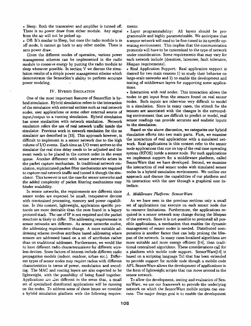
of SensorWare scripts that can run'on both the real sensor nodes as well as the simulated sensor nodes. The execu- tion environment inside a sensor node is closely modeled by the Sensor Execution Model. On our platform the Sensor Model runs as standalone UNIX process and provides the environment for the execution of SensorWare scripts. It includes the SensorWare mobile code API and a resource management scheme that mimics the execution of scripts as they would execute on a real sensor node. The Sen- sor Execution Model is attached to the simulated protocol stack through a sensor agent as shown in figure 6.
~ k
Fig. 6. Sensor Execution Model in SensorWare
To ensure that the external Sensor Execution Model pro- cess and the simulation are time synchronized, we apply a simple protocol. This protocol provides a timer abstrac- tion for the Sensor Model. The Sensor Model can schedule events using the simulator timers by transmitting its timer requests to the sensor agent. By passing an appropriate set of commands to the sensor agent the sensor agent can set a timer and subsequently notify the Sensor Model when the timer expires. When a packet is passed from the sensor agent to the external Sensor Model process, the simulation pauses and the Sensor Agent waits for a response from the Sensor Model. If the Sensor Model has a packet to transmit or it needs to schedule an event, it will pass the appropri- ate command to the Sensor Agent. If no packets need to be transmitted and no event needs to be scheduled, the Sensor Model will send an acknowledgement to the Sensor Agent. Once the acknowledgement has been received, the simulation execution will resume.
Currently, SensorSim is used a testbed to extend the functionality of SensorWare as well as to develop applica- tions in the form of scripts. Using our platform we can evaluate the power efficiency of distributed and centralized SensorWare applications. A short case study of the use of SensorWare on SensorSim is provided in section V.
B. Communication with Real Nodes
The need for communication with real nodes arises mainly from the difficulties in accurately modeling sensor data. Unlike the communication channel, the sensor chan- nel is very difficult to model. In many cases, we cannot have all the necessary parameters to construct a reason- able model for the sensor channel. As an example, we con: sider the case of a moving target. This target needs to be
tracked by a geophone and a microphone. In this scenario, both the ground and the air are parts of the sensor chan- nel. The stimuli for this channel are provided the by target plus additional other moving entities that can be consid- ered as background noise. Since such complex models are not yet well defined and understood, the use of real sensors can provide accurate and valid inputs to our simulations. Furthermore, the use of real sensor inputs can provide use- ful insight in constructing analytical models. In addition to generating sensor input for our simulations, the interac- tion with real nodes can be used for developing and testing new protocols on the real nodes. Although such approach is not possible for the physical and MAC layers, it can be used for developing routing protocols and applications.
To enable the interaction between real and simulated nodes, SensorSim provides a simulated protocol stack for each real node. This protocol stack is connected to the corresponding real nodes through a proxy and the gateway mechanism as shown in figure 3. The simulated protocol stack provides the radio and MAC layers and an optional routing layer for the real nodes. These layers are used to represent the real nodes in the network topology. The gateway workstation runs the gateway server and has a gateway sensor node attached to it. The gateway server can perform the appropriate packet format conversion (ns-to- sensor packet format and vise-versa) and tunnel the packets to the appropriate destination. This gateway configuration provide the required abstraction so that real and simulated nodes can interact. Inside the simulation, real nodes can be placed anywhere in the network topology.
One limitation of this method is synchronization between the simulation scheduler and protocol execution in the real nodes. Since real and simulated nodes are not time syn- chronized, real node timers cannot participate in the sim- ulation. We are currently considering a synchronization method that involves pausing the simulation and reorga- nizing events inside the simulator scheduler to ensure the correct order of execution of timer based events between the real and simulated sensor nodes.
The graphical user interface can be slaved to a running simulation to display the topology setup, the traffic be- tween the nodes and the battery levels of the simulated networks. Future versions of the GUI will also allow some user interactivity that will allow the user to configure the simulation setup.
V. RESULTS
A. Power Models
In this section we discuss the simulation result of a sen- sor network which utilizes a power management scheme to conserve energy. For the routing scheme, Dynamic Source Routing (DSR) is used and the traffic source of each sen- sor node is Constant Bit Rate (CBR) Agent that generates packets at a regular interval. The MAC Layer (figure 2) runs the power management algorithm that controls the operation modes of the Radio Model. The Physical Layer uses the information about the operation modes, the trans- mit power, and the data rate from the Radio Model for its
109
operation. This simulation setup demonstrates the Sen- sorSim's capability to simulate the software utilizing the resources of hardware. This is accomplished by having the MAC Layer (software) and the Physical Layer (software) utilize the resources of the Radio Model (hardware).
The Radio Model provides a flexibility to simulate dif- ferent kinds of hardware by characterizing each hardware with the function f(x) and g(y). For this simulation, the WaveLAN card [6] is characterized by configuring f(x) and g(y) of the Radio Model. The table 1 lists the value of f(x) and g(y) based on the numbers obtained from [6].
E nwgv usage of Ive diffe~nt trM11c kslM
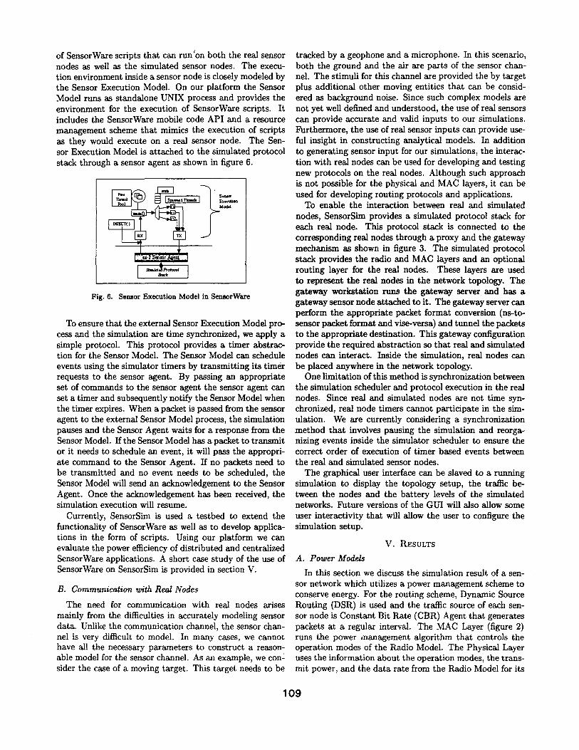
Fig. 8. a) Simulated Network in SensorSim, b) Energy Usage
[[ f (x) ] g(y) ] Total
Transmit .925W .5W 1.425W Receive .925W OW .925W Idle .925W OW .925W
Sleep,Off OW OW OW
TABLE I RADIO MODEL CONFIGURATION
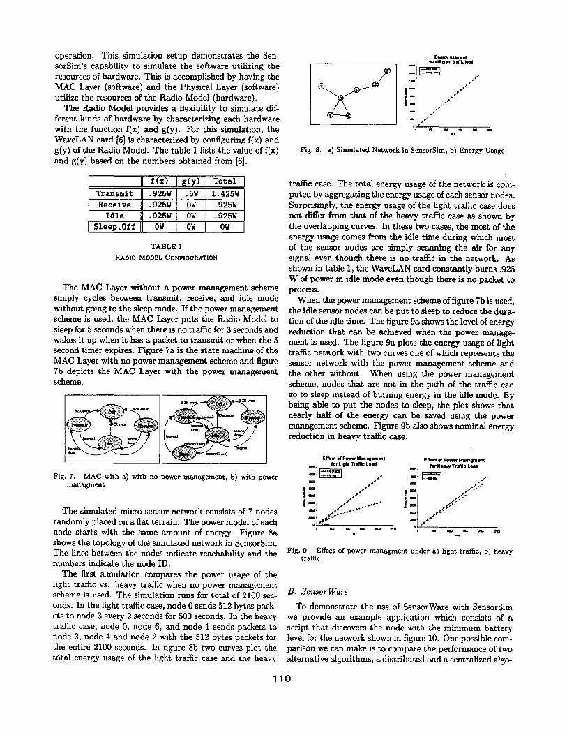
The MAC Layer without a power management scheme simply cycles between transmit, receive, and idle mode without going to the sleep mode. If the power management scheme is used, the MAC Layer puts the Radio Model to sleep for 5 seconds when there is no traffic for 3 seconds and wakes it up when it has a packet to transmit or when the 5 second timer expires. Figure 7a is the state machine of the MAC Layer with no power management scheme and figure 7b depicts the MAC Layer with the power management scheme.
Ljmmm(5
Fig. 7. MAC with a) with no power management, b) with power managment
The simulated micro sensor network consists of 7 nodes randomly placed on a flat terrain. The power model of each node starts with the same amount of energy. Figure 8a shows the topology of the simulated network in SensorSim. The lines between the nodes indicate reachability and the numbers indicate the node ID.
The first simulation compares the power usage of the light traffic vs. heavy traffic when no power management scheme is used. The simulation runs for total of 2100 sec- onds. In the light traffic case, node 0 sends 512 bytes pack- ets to node 3 every 2 seconds for 500 seconds. In the heavy traffic case, node 0, node 6, and node 1 sends packets to node 3, node 4 and node 2 with the 512 bytes packets for the entire 2100 seconds. In figure 8b two curves plot the total energy usage of the light traffic case and the heavy
traffic case. The total energy usage of the network is com- puted by aggregating the energy usage of each sensor nodes. Surprisingly, the energy usage of the light traffic case does not differ from that of the heavy traffic case as shown by the overlapping curves. In these two cases, the most of the energy usage comes from the idle time during which most of the sensor nodes are simply scanning the air for any signal even though there is no traffic in the network. As shown in table 1, the WaveLAN card constantly burns .925 W of power in idle mode even though there is no packet to process.
When the power management scheme of figure 7b is used, the idle sensor nodes can be put to sleep to reduce the dura- tion of the idle time. The figure 9a shows the level of energy reduction that can be achieved when the power manage- ment is used. The figure 9a plots the energy usage of light traffic network with two curves one of which represents the sensor network with the power management scheme and the other without. When using the power management scheme, nodes that are not in the path of the traffic can go to sleep instead of burning energy in the idle mode. By being able to put the nodes to sleep, the plot shows that nearly half of the energy can be saved using the power management scheme. Figure 9b also shows nominal energy reduction in heavy traffic case.
E f f e c t o f Povmr Management Effect Of P o w 4 r I V ~ n a g m w l ¢
~==m for Light Traff~ Load ~ Heavy Traffic L ~ l d
J_J.--
o i m I : 8 === z m :=m n m i ~ i ~ = m
. , *w
Fig. 9. Effect of power managment under a) light traffic, b) heavy traffic
B. SensorWare
To demonstrate the use of SensorWare with SensorSim we provide an example application which consists of a script that discovers the node with the minimum battery level for the network shown in figure 10. One possible com- parison we can make is to compare the performance of two alternative algorithms, a distributed and a centralized algo-
110
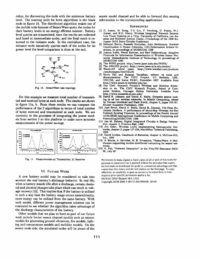
rithm, for discovering the node with the minimum battery level. The starting node for both algorithms is the black node in figure 10. The distributed algorithm makes use of the mobile code features of SensorWare query the nodes for their battery levels in an energy efficient manner. Battery level queries are transmitted, then the results are collected and fused at intermediate nodes, and the final result is re- turned to the initiator node. In the centralized case, the initiator node iteratively queries each of the nodes for its power level the level comparison is done at the end.
• 77Fo
7OY, 43F°
34~*
Fig. 10. SensorWare test topology
For this example we measure total number of transmit- ted and received bytes at each node. The results are shown in figure 11a) b. From these results we can compare the performance of the 2 algorithms in terms of total number of bytes received and transmitted at each node. We are currently in the processes of integrating the power mod- els from section 1 to this platform to make more accurate measurements of the power savings.
,~ ,llltl l~e,
,-t /\ - t / '~, i v \
I * I I i I @ ¢ I I I I i i i I I I
t' ~:1 I \ / \
l l l l l I D l l l l l l q q
sensor model channel and be able to forward this sensing information to the corresponding applications.
REFERENCES
[1] G. Asada, M. Dong, T.S. Lin, F. Newberg, G. Pottle, W.J. Kaiser, and H.O. Marcy. Wireless Integrated Network Sensors: Low Power Systems on a Chip. University of California, Los An- geles and Rockwell Science Center, Proceedings of the 1998 Eu- ropean Solid State Circuits Conference.
[2] Deborah Estrin, Ramesh Govindan, John Heidemann. Scalable Coordination in Sensor Networks. USC/Information Science In- stitute, In proceedings of MOBICOM 1999
[3] Joanna Kulik, Wendi Rabiner, and Hari Balakrishnan: Adaptive Protocols for Information Dissemination in Wireless Sensor Net- works. Massachusetts Institute of Technology, In proceedings of MOBICOM 1999
ii] The WINS project, http://www.janet.ucla.edu/WINS/ The AWAIRS project, http:i/www.janet.ucla.edu/awalrs/ WaveLAN white specs, http://www.wavelan.com/products /productspeca.html?id=25
[7] Kevin Fall and Kannan Varadhan, editors, ns notes and documentation. The VINT Project, UC Berkeley, LBL, USC/ISI, and Xerox PARC, November 1997. Available from http://www.mach.cs.berkeley.edu/ns/
[8] The CMU Monarch Project's Wireless and Mobility Exten- sion to ns, The CMU Monarch Project, School of Com- puter Science, Carnegie Mellon University. Avalalbe from http://www.monarch.cs.cmu.edu/
[9] David B. Johnson and David A. Maltz. Dynamic source rout- ing in ad hoc wireless networks. In Mobile Computing, edited by Tomasz Imielinski and Hank Korth, chapter 5, pages 153-181. Kluwer Academic Publishers, 1996.
[10] Josh Broch, David A. Maltz, David B. Johnson, Yih-Chun Hu, Jorjeta Jetcheva. A performance of Multi-Hop Wireless Ad Hoc Network Routing Protocols. In proceedings of the Fourth Annual ACM/IEEE International Conference on Mobile Computing and Networking(MOBICOM) 1998
[11] Jan M. Rabaey. Digital Integrated Circuits A Design Perspec- tive, chapter 5. Prentice Hall, 1996
[12] Jim Geier, Wireless LANs Implementing Interoperable Net- works, chapter 2, pages 127-159, MacMillan Technical Publishing, 1999
[13] David Linden, Handbook of Batteries, chapter 3, McGraw-Hill, Inc., 1995
[14] A. Boulis, A. Savvides, M. B. Srivastava, "SensorWare: A Mid- dleware supporting mobile distributed computing for sensor net- works.
[15] K. Fall, "Network Emulation" in the Vint/NS Simulator ISCC 99, July 99.
Fig. 11. Measurements a) Transmitter, b) Receiver
V I . FUTURE WORK
A new ba t t e ry mode l m a y be cons idered to t ake into account the real b a t t e r y ' s d ischarge behavior . In real life, when a ba t t e ry s tands idle af ter a discharge, ce r ta in chemi- cal and physical changes take place which can resul t in vol t - age recovery [13]. This implies t h a t if t he b a t t e r y is ut i l ized in such a way t h a t the b a t t e r y usage occurs in te rmi t ten t ly , more energy can be ut i l ized f rom the same ba t te ry . W i t h such model , different power m a n a g e m e n t schemes can be eva lua ted to see whe the r the a lgo r i t hm takes advan tage of the discharge character is t ics of the bat tery•
Othe r models t h a t we p lan to have as pa r t of our fu tu re work include be t t e r sensor channel models such as seismic models for gene ra t ing g round v ibra t ions , fire models , l ight- ing and t e m p e r a t u r e models and mobi l i ty models . On the sensor node side, t he s imula ted nodes will be aware of t he
Permission to make digital or hard copies of all or part of this work for personal or classroom use is granted without fee provided that copies are not made or distributed for profit ol" commercial advantage and that copies bear this notice and the full citation on the first page. To copy otherwise, to republish, to post on servers or to redistribute to lists, requires prior specific permission and/or a fee. MSWIM 2000 Boston MA USA Copyright ACM 2000 1-58113-304-9/00/08...$5.00
111