separating axis test (sat) and support points in 2d
TRANSCRIPT
Separating Axis Test (SAT) and Support Points in 2D
Randy Gaul
Special thanks to Dirk Gregorius for his GDC 2013 lecture and slides

Overview - Separating Axis Test (SAT)
• Why use SAT
• Theory
• Implementation
• Support Points
• Implementation
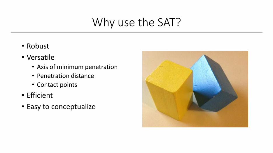
Why use the SAT?
• Robust
• Versatile• Axis of minimum penetration
• Penetration distance
• Contact points
• Efficient
• Easy to conceptualize
SAT Versatility
• Collision detection is easy
• Resolving collision is hard• Realistic bouncing, stacking
• Resolution requires:• Axis of minimum penetration
• Penetration distance
• Contact points
• SAT can give us all info needed for resolution• Gathering this information is called “manifold generation”
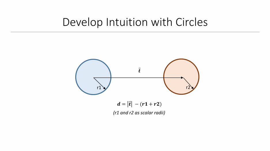
Develop Intuition with Circles
𝒅 = 𝒕 − (𝒓𝟏 + 𝒓𝟐)
𝒕
r1 r2
(r1 and r2 as scalar radii)

Develop Intuition with Circles
𝒕
r1
r2
• Collision when d is positive
• No collision when d is negative
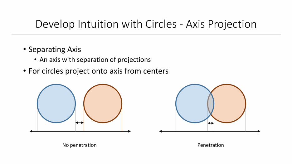
Develop Intuition with Circles - Axis Projection
• Separating Axis• An axis with separation of projections
• For circles project onto axis from centers
No penetration Penetration
SAT - Definition
• Collision• Projections onto all axes are not separating (overlapping)
• No collision• At least one axis contains separating projections
• Note about No Collision case:• Any positive number of axes can be separating
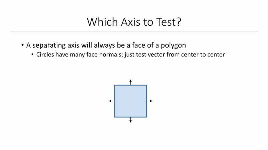
Which Axis to Test?
• A separating axis will always be a face of a polygon• Circles have many face normals; just test vector from center to center
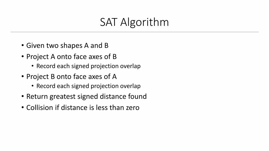
SAT Algorithm
• Given two shapes A and B
• Project A onto face axes of B• Record each signed projection overlap
• Project B onto face axes of A• Record each signed projection overlap
• Return greatest signed distance found
• Collision if distance is less than zero

SAT Implementation (Pseudo Code)
float FindLeastPenetration( Polygon A, Polygon B )
{
float bestDistance = -FLT_MAX;
for(int i = 0; i < A->faceCount; ++i)
Vec2 p = A->faces[i];
float d = Project( A, B, p );
// Store greatest distance
if(d > bestDistance)
bestDistance = d;
return bestDistance;
}
Call twice, flip objects A and B

SAT Implementation : Note
• The largest signed distance will be penetration depth• If less than zero then colliding
• Keep track of face index that supplied penetration depth• This face’s normal will be resolution vector
• This face is the axis of minimum penetration
// Store greatest distance
if(d > bestDistance)
bestDistance = d;
bestIndex = i;
return bestDistance AND bestIndex;

SAT : Optimization
• Projection is expensive• Must transform vertices of both shapes and compute overlap
• Computing support points is faster• Instead of overlap, compute point to line distance
• Support points act as alternative to actual projections
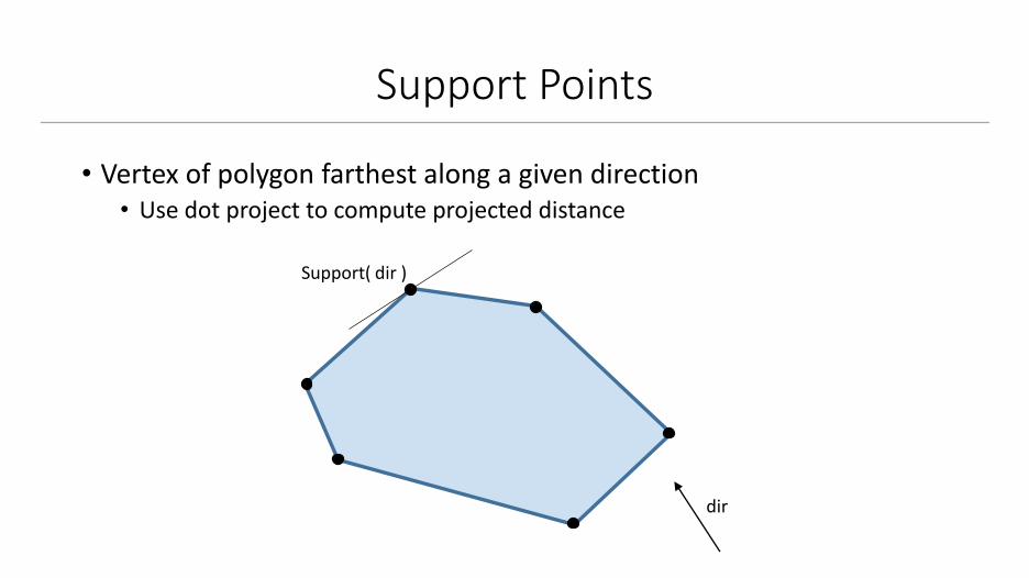
Support Points
• Vertex of polygon farthest along a given direction• Use dot project to compute projected distance
dir
Support( dir )

Support Points Implementation (Pseudo Code)
Vec2 Polygon::GetSupport( const Vec2& dir )
{
float bestProjection = -FLT_MAX;
Vec2 bestVertex;
for(int i = 0; i < vertexCount; ++i)
Vec2 v = vertices[i];
real projection = Dot( v, dir );
if(projection > bestProjection)
bestVertex = v;
bestProjection = projection;
return bestVertex;
}

Optimized Penetration Calculation
Distance point to plane:d = n ∙ (p1 – p2)
p2 : any point along the plane
p1 p2n
Support( -n )
p
n
d = n ∙ (Support( -n ) – p)

SAT Collision Test
bool SAT( Polygon A, Polygon B )
{
if(FindLeastPenetration( A, B ) > 0.0f)
return false;
if(FindLeastPenetration( B, A ) > 0.0f)
return false;
return true;
}

Finding Contact Points
• Point of contact required for resolution• At most, two points can be used
A B
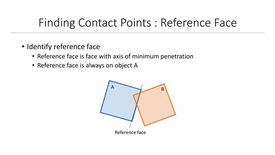
Finding Contact Points : Reference Face
• Identify reference face• Reference face is face with axis of minimum penetration
• Reference face is always on object A
A B
Reference face
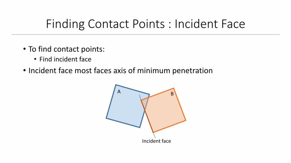
Finding Contact Points : Incident Face
• To find contact points:• Find incident face
• Incident face most faces axis of minimum penetration
Incident face
A B
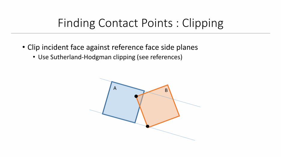
Finding Contact Points : Clipping
• Clip incident face against reference face side planes• Use Sutherland-Hodgman clipping (see references)
A B

Finding Contact Points : Culling
• Only keep points behind reference face• Compute signed distance, test sign (positive or negative)
A B
Checkpoint
• Can detect collisions with SAT
• Understand support points• Can optimize SAT with support points
• Record axis of minimum penetration• Normal to this axis is resolution vector
• Compute contact points with clipping

Optimizations
• If separating axis is found• Store this axis, check axis next frame between same two objects
• Fast early out
• Can detect if face normals are nearly parallel• Testing parallel axes is redundant, don’t do it!
• Can cull redundant axes from both shapes, not just one
• Hill climbing for Support search• Test first vertex and both adjecent
• Loop in direction with greatest delta
• Stop searching once delta is positive

References
• Dirk Gregorius’s 2013 GDC Slides – Box2D.org downloads
• Box2D source code
• Patrick Moghames – Graphics professor (Sutherland-Hodgmanclipping)
• Impulse Engine – randygaul.net
• All of Erin Catto’s GDC Slides – Box2D.org