september 2015 f11 tracon zjx 7110.104a central … tracon sop.pdf · central florida tracon (f11)...
TRANSCRIPT

SEPTEMBER 2015 F11 TRACON ZJX 7110.104A Central Florida TRACON (F11) Standing Operating Procedures
1
1-1. General
Information obtained in this document is for use on the VATSIM network and in no way intended for real world purpose. This document, site and organization are not affiliated with the FAA, actual Central Florida TRACON or any other governing aviation body. The purpose of this document is to establish standard operating procedures within the Central Florida TRACON, its Air Traffic Control Towers (ATCT), and En-Route controllers. You should be familiar with this document prior to controlling within F11. This document describes procedures meant for busier times, and can be taken as guidelines so long as affected controllers approval of the deviation prior to execution. 1-2. Sectors
TRACON
Sector
Name
Call Sign
Relief
Callsign
Frequency
Voice Room
ID
Tag
DRE*
Dep. Radar
East
MCO_E_APP
4E
124.800
MCO_4E
4E
E
DRW
Dep. Radar
West
MCO_W_APP
4W
120.150
MCO_4W
4W
W
ARB
Arr. Radar
Bitho
MCO_B_APP
4B
125.550
MCO_4B
4B
B
ARL
Arr. Radar
Leese
MCO_L_APP
4L
134.050
MCO_4L
4L
L
ARM
Arr. Radar
Monitor
MCO_M_APP
4M
127.750
MCO_4M
4M
M
SRD
Sat. Radar
Disney
MCO_D_APP
4D
119.400
MCO_4D
4D
D
SRK
Sat. Radar
Kape
MCO_K_APP
4K
134.950
MCO_4K
4K
K
SRN
Sat. Radar
North
MCO_N_APP
4N
121.100
MCO_4N
4N
N
SRS
Sat. Radar
South
MCO_S_APP
4S
132.650
MCO_4S
4S
S

JUNE 2015 F11 TRACON ZJX 7110.104A Central Florida TRACON (F11) Standing Operating Procedures
2
1-3. Order for Opening Sectors
The primary position is DRE. DRE shall be the first sector open. After DRE, additional controllers may opt to open an Arrival Radar or DRW. Satellite Radar sectors may only be opened during events as prescribed by the Events Coordinator, Air Traffic Manager, Deputy Air Traffic Manager or Training Administrator to have controllers staff adjacent sectors to provide greater coverage. See Figure 1-3-1 for a graphical breakdown of sector combinations.
F11 TRACON
Figure 1-3-1. Break down of sector combinations.

JUNE 2015 F11 TRACON ZJX 7110.104A Central Florida TRACON (F11) Standing Operating Procedures
3
1-4. Departure Gates
Departure gates, by standard operations, are considered closed unless otherwise instructed by the overlying En-Route controllers. En-Route controllers shall individually specify the gate(s) they want active and the estimated length of time to utilize the gates. F11 Controllers are not obligated to notify ATCT controllers of the gates as standard operating procedures for them is to always issue the gates. When departure gates are not opened, all aircraft shall be sent direct to the first fix of their route or along their Standard Instrument Departure. Aircraft flying on a pilot navigation SID are exempt from departure gate procedures.
Figure 1-4-1. Departure Gates

JUNE 2015 F11 TRACON ZJX 7110.104A Central Florida TRACON (F11) Standing Operating Procedures
4
1-5. VFR Aircraft
VFR Aircraft within the Class Bravo airspace shall, to the extent possible, be kept below 5,000 feet and with the appropriate Satellite Radar sectors. ATCTs will keep aircraft outside the Class Bravo airspace not requesting Flight Following and switch them to CTAF.
1-6. Handoffs
Orlando International Airport ATCT is a radar tower, radar handoffs shall be accomplished prior to aircraft turning to final. Non-acceptance of the radar handoff shall not constitute disapproval for the aircraft’s approach unless a visible conflict exists. No other tower shall receive a radar handoff within the F11 complex. JUNE 2011 F11 TRACON ZJX 7110.104A Handoffs to other F11 sectors or inter-facility handoffs shall be completed as soon as the aircraft has received instructions to depart the F11 airspace and conflicts have been resolved. If this means the aircraft is at 4,000 feet, climbing to 16,000 and turning direct to Cross City when the aircraft is clear of conflicts, then a handoff shall still be initiated.
1-7. Releases and Rolling Calls
F11 Departure sectors give automatic releases to all departures from Orlando International Airport when departures follow the standard departure procedures as specified in paragraph 1-8 in this document and the appropriate section within the MCO ATCT SOP documentation. All other airports within F11 shall request a release for all departures receiving radar services. Upon approval of the release, the release shall be good for five minutes. Upon issuance of the takeoff clearance, a departure message shall be sent to the appropriate departure sector. This can be accomplished non-verbally by the Local Controller ensuring the aircraft is squawking the appropriate code and mode C is enabled when airborne. Failing this, a “non-tag” message should be sent to the appropriate departure controlling consisting of its approximate location, callsign, and departure runway (example, “1 mile north, UAL147, 36R”).

JUNE 2015 F11 TRACON ZJX 7110.104A Central Florida TRACON (F11) Standing Operating Procedures
5
1-8. Scratch Pads The following scratch pad format is the standard format for use within the Jacksonville Air Route Traffic Control Center for coordination between the Approach Controllers and ATCT controllers. It uses a 3 letter format consisting of XYY where X identifies the type of approach and YY consists of the runway truncated to 2 characters. For example, runway 9 would be 09, runway 18R would be 8R and so on.
Type Letter
Localizer L
RNAV (GPS/RNP) G
ILS I
VOR R
TACAN T
NDB N
Visual V
Overhead Break B
F11 Controllers shall ensure that all scratch pads are removed prior to initiating a radar handoff with the En-Route sector. Departure scratch pads will be placed by MCO ATCT for all departing aircraft, see Appendix C. 1-9. Temporary Altitude Use of temporary altitude fields is unauthorized for TRACON and ATCT controllers.

JUNE 2015 F11 TRACON ZJX 7110.104A Central Florida TRACON (F11) Standing Operating Procedures
6
Chapter 2. Departure Radar East (DRE) and Departure Radar West (DRW)
2-1. Position Responsibilities Unless otherwise coordinated, DRE is responsible for all departures from the deck for Orlando International Airport and all other departures and airspace. 2-2. Departures Gates Shall be in accordance with Paragraph 1-4 of this document. Initial Climb Out Altitude If there will be conflicting downwind traffic, all aircraft shall receive an initial climb to 8000. Once aircraft are clear of conflicts the aircraft shall be issued a climb to the altitudes noted below or less if filed in the flight plan. Eastern Side When Departure Gates are in use, aircraft shall exit out of ATLAS/TPSTR at or climbing to 14,000 (unless filed lower) on a heading of 140-160 prior to handoff with the appropriate Miami En-Route Control sector. Aircraft exiting WORMS and not destined for the JAX or DAB ATCT complexes shall be at or climbing to 16,000 for turbojets or 12,000 for turboprops/pistons and sent direct WORMS. Aircraft transitioning to the JAX and DAB ATCT complex shall cross WORMS at or climbing to 10,000 (or lower filed) and be sent through the highlighted area on figure 1-4-1 on a heading to join the outbound ORL 355 radial unless otherwise coordinated. Western Side When Departure Gates are in use, aircraft shall exit out of FMYDT at or climbing to 16,000 (unless filed lower) on a heading of 180 prior to handoff to the appropriate Miami En-Route Control sector. Aircraft exiting CAMDT shall be on a heading between 270 and 290 or as coordinated with Jacksonville En-Route Control at or climbing to 16,000. Aircraft exiting KNEED shall be on a heading of 250 and handed off to Tampa Approach or Miami Center. Aircraft transitioning into the Ocala Sector of the Jacksonville ACTC complex and VIZTA shall be sent toward CERMO level at an even altitude (10,000 feet or below) and handed off to Jacksonville approach.

JUNE 2015 F11 TRACON ZJX 7110.104A Central Florida TRACON (F11) Standing Operating Procedures
7
Aircraft transitioning into the TAMPA TRACON as over flights or F-11 departures shall be handed off to Tampa Approach at an even altitude (12,000 or below) and as best as practical on the DADES or LZARD arrivals. Piston WORMS departures shall be vectored direct to WORMS or instructed to join the outbound ORL 355 radial. In Trail Spacing F-11 must give all En-Route Controllers 7 miles increasing over the same fix or DTA. This can be adjusted based on volume or weather by using the TMU display on the ZJX website. 2-3. Airspace Diagrams Figure 2-3-1. MCO North Flow
Figure 2-3-1. MCO North Flow

JUNE 2015 F11 TRACON ZJX 7110.104A Central Florida TRACON (F11) Standing Operating Procedures
8
Figure 2-3-2. MCO South Flow
2-4. F11 Professional Sector File Maps
North Flow On the F11 “Pro”, map “026 DEP RDR NORTH FLOW” will draw the radar video map for north flow. If working combined, enable map “001 SAT NORTH” to view the necessary information for SFB, ORL, ISM and MLB. Alternatively, you can enable “Runway Centerlines” in VRC. Map “019 ARR NORTH OPS SIMPLE” will draw necessary information for final approach, or use “030 FINAL NORTH OPS” for information specific to ARM North Operations.

JUNE 2015 F11 TRACON ZJX 7110.104A Central Florida TRACON (F11) Standing Operating Procedures
9
South Flow On the F11 “Pro”, map “027 DEP RDR SOUTH FLOW” will draw the radar video map for north flow. If working combined, enable map “002 SAT SOUTH” to view the necessary information for SFB, ORL, ISM and MLB. Alternatively, you can enable “Runway Centerlines” in VRC. Map “020 ARR SOUTH OPS SIMPLE” will draw necessary information for final approach, or use “030 FINAL SOUTH OPS” for information specific to ARM North Operations. 2-5. South Operations DRE and DRW shall jointly share the airspace highlighted in orange in figure 2-3-2 and have control for turns and climbs without point outs to the adjacent sector. This does not alleviate the separation and traffic advisory requirements between aircraft within this airspace. Extreme caution should be exercised within this airspace to ensure separation. 2-6. Sanford Operations If Satellite departure is offline, northbound Sanford departures shall be turned to the north. Issue a climb to 11,000 feet or lower if filed and hand off the aircraft to Daytona Approach. If Daytona Approach is offline, hand the aircraft off to Jacksonville Center. Northbound traffic will then be vectored to join the J53 north of WORMS or sent on course.

JUNE 2015 F11 TRACON ZJX 7110.104A Central Florida TRACON (F11) Standing Operating Procedures
10
Chapter 3. Arrival Radar Leese (ARL) and Arrival Radar Bitho (ARB)
3-1. Position Responsibilities Unless otherwise coordinated, ARL and ARB’s primary responsibilities is regulating all arrival traffic to the Orlando area. ARB is also responsible for arrivals via the BITHO STAR into MLB. ARL’s and ARB’s primary responsibilities are to sequence arrival traffic. 3-2. MCO Arrivals MCO Arrivals shall be vectored and descended within the Arrival Radar airspace. Aircraft approaching opposite the flow of MCO shall be descended to 9000 until clear of outbound conflicts and then descended down to 5000 and placed onto a radar vectored downwind for the active runways. Adjacent the departure numbers, controllers shall have initiated a radar handoff to ARM if staffed or the controller covering ARM if applicable. Aircraft approaching in the direction of the flow shall be descended to 4000 and handed off to ARM as soon as applicable. ARL shall be initially assigned RWY 18R or 36R based on airport operations. ARB shall initially assign RWY 17L or 35R based on airport operations. These runways should be reflected in the scratchpad. ARM may amend the final runway assignment based on company location on the field and terminal or by pilot request. ARM vertical airspace is from SFC to 5000 ft. AGL. ARL and ARB shall not, unless covering ARM’s airspace, vector aircraft onto base, interception angles (doglegs) or final. Aircraft may be vectored by ARL and ARB onto a base when aircraft are approaching from the direction of flow (IE, they are arriving from the north, traveling south during southern operations). 3-3. Satellite Arrivals Aircraft shall be moved out of the way of MCO’s arrival sequence, descended to 6000, and handed off to the appropriate Satellite Radar sector or sector covering that portion of the airspace. Once the handoff is received, Satellite Radar shall descend aircraft to 5000 and proceed with sequence and further decent. ISM – Satellite Radar Disney ORL – Satellite Radar Disney (east operations) or Satellite Radar North (west operations) SFB – Satellite Radar North MLB – Satellite Radar South COP – Satellite Radar Kape or Satellite Radar South if SRK not open

JUNE 2015 F11 TRACON ZJX 7110.104A Central Florida TRACON (F11) Standing Operating Procedures
11
3-4. Missed Approaches Aircraft conducting practice approaches or conduct a missed approach will be vectored toward the appropriate Arrival Radar airspace by either DRE or DRW, climbed to 5000 and then handed off to the appropriate Arrival Radar sector. These aircraft shall be re-sequenced unless pilot requests otherwise. 3-5. Airspace Consolidation Under normal circumstances, ARL and ARB shall not be consolidated into one radar unless the entire TRACON is consolidated into one position. When ARM is not staffed, its airspace shall be assigned to the staffed Arrival Radar sector. In instances where both Arrival Radar sectors are staffed, ARL and ARB both control that airspace and are responsible for vectoring aircraft onto the appropriate final approach course while simultaneously ensuring separation between other arriving aircraft. This does not preclude the requirement for traffic calls when necessary and does not remove the requirement for separation on final. Scratch pad usage is vital during these times to ensure proper non-verbal coordination between both positions as well as the local control position(s). 3-6. Daytona Arrivals As best as practical, Southeast arrivals through F-11 into the Daytona ATCT complex shall arrive via the V3 airway at odd altitudes. Altitudes for the border crossing shall be coordinated between DRE, Satellite Approach, and Daytona Approach. Southwest Arrivals through the F-11 into Daytona Approach shall arrive through a vector to join V152 to KIZER at odd altitudes. Altitudes for boarder crossing shall be coordinated between DRW, Satellite Approach and Daytona Approach.

JUNE 2015 F11 TRACON ZJX 7110.104A Central Florida TRACON (F11) Standing Operating Procedures
12
Figure 3-7-1. Arrival Radar sectors, MCO North Operations

JUNE 2015 F11 TRACON ZJX 7110.104A Central Florida TRACON (F11) Standing Operating Procedures
13
Figure 3-7-2. Arrival Radar sectors, MCO South Operations

JUNE 2015 F11 TRACON ZJX 7110.104A Central Florida TRACON (F11) Standing Operating Procedures
14
Chapter 4. Satellite Radar North (SRN)
4-1. Sector Responsibilities Satellite Radar North is responsible for the traffic into and out of satellite airfields within its area of jurisdiction. 4-2. Orlando Executive Responsibilities SRN is responsible for departures during normal Orlando Executive operations (east flow) and arrivals when Executive is in southern or western operations. 4-3. Orlando Sanford International Responsibilities SRN is responsible for arriving and departing traffic into and out of SFB. 4-4. Departures Departing IFR traffic with a cruise altitude at or above 5000 shall receive a climb instruction to 5000 and handed off to the appropriate Departure Radar sector. Aircraft should also be turned direct to the first fix on their route when applicable, IAW paragraph 4-6, unless otherwise coordinated. Northbound traffic shall be turned to the north and handed off to Daytona Approach for a filed altitude of 5000 feet or less. If Daytona Approach is offline, hand off the aircraft to Jacksonville Center. For altitudes greater than 5000 feet, handoff the aircraft to the appropriate Departure Radar Sector. Northbound traffic will then be vectored to join the J53 at or north of WORMS and be sent on course. SRN has authorization for airspace penetration into DRW or DRE for J53 departures from SFB. Aircraft shall be climbed to 11000 and handed off to Daytona Approach or Jacksonville Center. 4-5. Arrivals SRN should expect arriving traffic to be descending to or level at 5000 and upon initial contact shall descend them beneath the ceiling of SRN unless otherwise coordinated or requested by the pilot. Aircraft should be turned away from the MCO arrival sequence as soon as practical.

JUNE 2015 F11 TRACON ZJX 7110.104A Central Florida TRACON (F11) Standing Operating Procedures
15
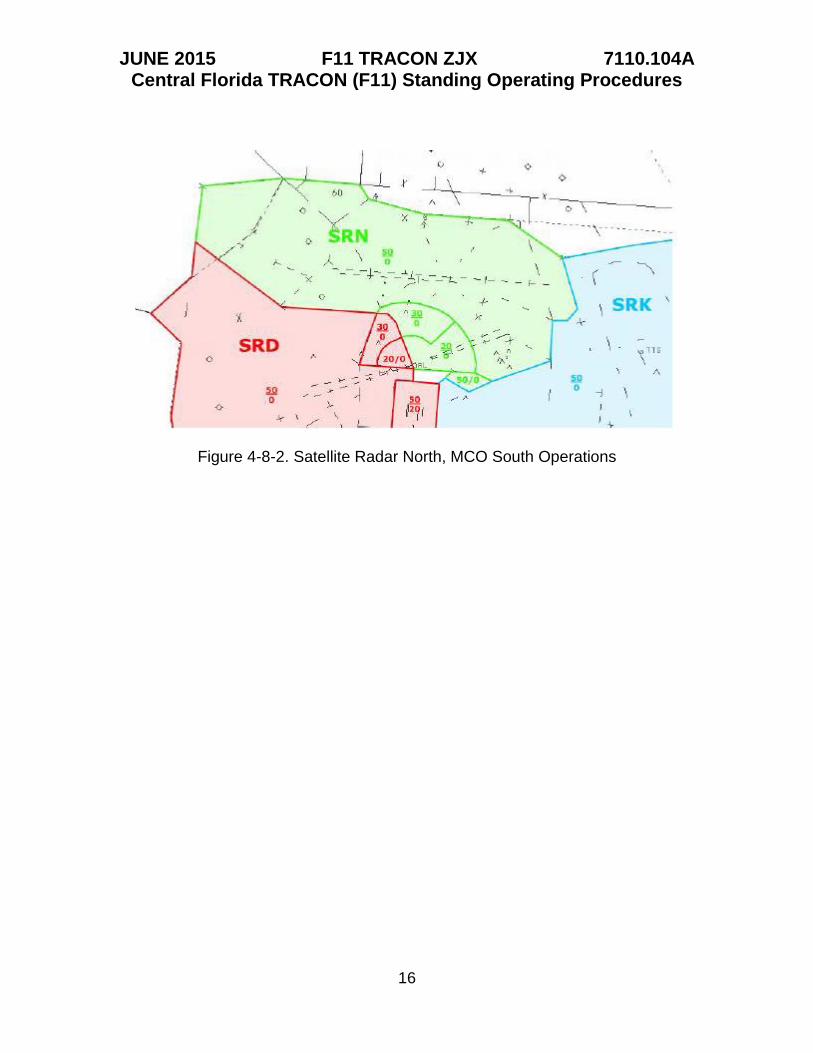
4-6. Departure Gates When notified departure gates are in effect, SRN shall send aircraft with a filed cruise above 5000 in the general cardinal direction of the departure gate prior to handing off to DRE or DRW. In the event of an aircraft with a fast rate of climb, such turn shall be issued in combination of the frequency change. Aircraft departing through CAMDT shall be turned westward, WORMS northward, ATLAS eastward and KLMAN westward. At no time shall an aircraft be turned southward unless otherwise approved by DRE or DRW as appropriate unless such aircraft is a departure from LEE. 4-7. Airspace Consolidation SRN may not be consolidated with any other Satellite Radar sector or Arrival Radar sector. When consolidating with Departure Radar sector, it shall consolidate with DRE. 4-8. Airspace Diagrams SRN’s altitudes are broken up as indicated below.
Figure 4-8-1. Satellite Radar North, MCO North Operations
JUNE 2015 F11 TRACON ZJX 7110.104A Central Florida TRACON (F11) Standing Operating Procedures
16
Figure 4-8-2. Satellite Radar North, MCO South Operations

JUNE 2015 F11 TRACON ZJX 7110.104A Central Florida TRACON (F11) Standing Operating Procedures
17
Chapter 5. Satellite Radar Disney (SRD)
SRD is responsible for the traffic around Walt Disney World, ISM, and transitioning aircraft between MCO and the Tampa ATCT. 5-2. ISM Responsibilities SRD is responsible for arriving and departing traffic into and out of ISM. Care should be taken so that IFR aircraft do not penetrate the Walt Disney World TFR. 5-3. Walt Disney World TFR As a long term TFR, VFR aircraft approaching the TFR airspace shall receive notification of the TFR and advised to turn away from it. IFR aircraft shall be climbed to an altitude above 3000 prior to the TFR if vectors away are not possible. IFR aircraft requesting to cross Walt Disney World shall cross above 3000. 5-4. Departures Departing IFR traffic with a cruise altitude at or above 5000 shall receive a climb instruction to 5000 and handed off to the appropriate Departure Radar sector. Aircraft should also be turned direct to the first fix on their route when applicable, IAW paragraph 5-6, unless otherwise coordinated. 5-5. Arrivals SRD should expect arriving traffic to be descending to or level at 5000 and upon initial contact shall descend them beneath the ceiling of SRD unless otherwise coordinated or requested by the pilot. Aircraft should be turned away from the MCO arrival sequence as soon as practical. 5-6. Departure Gates When notified departure gates are in effect, SRD shall send aircraft with a filed cruise above 5000 in the general cardinal direction of the departure gate prior to handing off to DRW. In the event of an aircraft with a fast rate of climb, such turn shall be issued in combination of the frequency change. Aircraft departing through CAMDT shall be turned toward CAMDT, WORMS northward, ATLAS northward and KLMAN southward. At no time shall an aircraft be turned southward near the MCO Arrival area.

JUNE 2015 F11 TRACON ZJX 7110.104A Central Florida TRACON (F11) Standing Operating Procedures
18
5-7. Airspace Consolidation SRD may not be consolidated with any other Satellite Radar sector or Arrival Radar sector. When consolidating with Departure Radar sector, it shall consolidate with DRW, or DRE when DRW is consolidated with DRE. 5-8. VFR Transitions VFR Transitions traveling eastward that will cross the MCO Departure Corridor or through ARM’s airspace shall, to the extent possible, be vectored northbound to cross over the MCO airfield at or above 2000. Helicopters and Piston aircraft, and any aircraft that requests, may cross over MCO below 2000 but a radar handoff must be effected to tower with a communications transfer completed prior to entering MCO ATCT’s airspace. 5-8. Airspace Diagrams
Figure 5-8-1. Satellite Radar Disney sector, MCO South Flow (left) and MCO North Flow (right)

JUNE 2015 F11 TRACON ZJX 7110.104A Central Florida TRACON (F11) Standing Operating Procedures
19
Chapter 6. Satellite Radar South (SRS) and Satellite Radar Kape (SRK)
6-1. Sector Responsibilities SRS is responsible for arrivals into Melbourne and Melbourne satellite airports and any other airfield within its area of jurisdiction. SRK is responsible for arrivals into Patrick AFB and satellites and all other minor airfields within its area of jurisdiction. 6-2. Airspace Consolidation Under normal circumstances, and unless otherwise coordinated, SRK shall be consolidated with SRS unless released to DRE by SRS. 6-3. Departures Departing IFR traffic with a cruise altitude at or above 5000 shall receive a climb instruction to 5000 and handed off to the appropriate Departure Radar sector. Aircraft should also be turned direct to the first fix on their route when applicable, IAW paragraph 6-5, unless otherwise coordinated. 6-4. Arrivals SRS/SRK should expect arriving traffic to be descending to or level at 5000 and upon initial contact shall descend them beneath the ceiling of SRS/SRK unless otherwise coordinated or requested by the pilot. Aircraft should be turned away from the MCO arrival sequence as soon as practical. 6-5. Departure Gates When notified departure gates are in effect, SRS/SRK shall send aircraft with a filed cruise above 5000 in the general cardinal direction of the departure gate prior to handing off to DRE. In the event of an aircraft with a fast rate of climb, such turn shall be issued in combination of the frequency change. Aircraft departing through CAMDT shall be turned toward westward, WORMS northward, ATLAS toward MLB/southward and KLMAN westward.

JUNE 2015 F11 TRACON ZJX 7110.104A Central Florida TRACON (F11) Standing Operating Procedures
20
6-6. Airspace Diagrams
Airspace Diagrams are listed below.
Figure 6-6-1. Satellite Radar South (SRS) and Satellite Radar Kape (SRK). MCO
South Operations (left) MCO North Operations (right)

JUNE 2015 F11 TRACON ZJX 7110.104A Central Florida TRACON (F11) Standing Operating Procedures
21
Appendix A. Radar Identifiers for Interfacility Handoffs
F11 Complex ATCTs DAB ATCTs
JAX ATCTs
CALLSIGN FREQUENCY ID TAG
MCO_E_TWR 118.450 4T T
MCO_W_TWR 124.300 4S T
CALLSIGN FREQUENCY SECTOR DESC. ID TAG
DAB_H_APP 125.720 Daytona High Approach 5H H
DAB_M_APP 118.850 Daytona Mateo Approach
5M M
DAB_L_APP 127.070 Daytona Lamma Approach
5L L
DAB_F_APP 125.800 Daytona Final Approach
5F F
CALLSIGN FREQUENCY SECTOR DESC. ID TAG
JAX_N_APP 127.000 Jacksonville North Approach
3N N
JAX_S_APP 119.000 Jacksonville South Approach
3S S
JAX_J_APP 119.850 Jacksonville Final Approach
3J J
JAX_L_APP 124.900 Jacksonville Satellite Approach
3L L
JAX_V_APP 118.600 Jacksonville Vitts Approach
3V V

JUNE 2015 F11 TRACON ZJX 7110.104A Central Florida TRACON (F11) Standing Operating Procedures
22
TPA ATCTs
Appendix A. Radar Identifiers for Interfacility Handoffs ZJX EN-ROUTE
ZMA EN-ROUTE
CALLSIGN FREQUENCY SECTOR DESC. ID TAG
TPA_B_DEP 135.500 East Departure 9B B
TPA_D_DEP 118.800 West Departure 9D D
TPA_G_DEP 134.250 South Departure 9G G
TPA_E_APP 118.150 East Arrival 9E E
TPA_F_APP 118.500 TPA Final 9F F
TPA_L_APP 119.900 East Satellite 9L L
TPA_M_APP 126.000 MacDill 9M M
TPA_P_APP 125.300 West Satellite 9P P
TPA_R_APP 120.650 Lakeland Low 9R R
TPA_S_APP 119.650 South Satellite 9S S
TPA_W_APP 132.520 West Arrival 9W W
CALLSIGN FREQUENCY SECTOR DESC. ID TAG
JAX_10_CTR (PRI) 135.050 METTA LOW C10 C
JAX_13_CTR 134.450 ASHBURN LOW C13 C
JAX_15_CTR 133.320 OCALA LOW C15 C
JAX_30_CTR 124.770 NEPTA HIGH C30 C
JAX_33_CTR 134.850 TORRY HIGH C33 C
CALLSIGN FREQUENCY ID TAG
MIA_3_CTR (PRI) 132.250 M03 M
MIA_17_CTR 128.650 M17 M
MIA_22_CTR 133.470 M22 M
MIA_23_CTR 126.950 M23 M
MIA_64_CTR 126.520 M64 M
MIA_65_CTR 125.070 M65 M
MIA_67_CTR 127.20 M67 M

JUNE 2015 F11 TRACON ZJX 7110.104A Central Florida TRACON (F11) Standing Operating Procedures
23
For use with the “F11 Pro” POF. Sector IDs will be different for ATCT positions in the primary.
Appendix B. Video Map Descriptions

JUNE 2015 F11 TRACON ZJX 7110.104A Central Florida TRACON (F11) Standing Operating Procedures
24
Appendix C. MCO ATCT Scratchpads
Approach Scratchpads
NAME DESCRIPTION
000 AIRPORT DIAGRAM Ground Layout for MCO ATCT for use by GC and CD
001 SAT NORTH Satellite Radar Map when MCO is in North Operations
002 SAT SOUTH Satellite Radar Map when MCO is in South Operations
003 ORLANDO AREA FINALS Extended Runway Centerlines for primary airports in F11 complex
005 MCO FINAL NTZ MCO Non-Transgression Zone Markings
006 VFR MAP Lakes and Major Highways
008 MCO TWR MAP Major Markings meant for MCO ATCT use
009 LOW AIRWAY MAP A map of all the low altitude airways
001 SAT NORTH Satellite Radar Map when MCO is in North Operations
002 SAT SOUTH Satellite Radar Map when MCO is in South Operations
003 ORLANDO AREA FINALS Extended Runway Centerlines for primary airports in F11 complex
010 GPS MAP Map of GPS approaches
011 HIGH AIRWAY MAP Map of all high altitude airways
013 AIRPORTS Draws all the airports within the F11 Complex
014 ARL/ARB SOUTH OPS Advanced markings for ARL/ARB when MCO is in South Operations
015 ARL/ARB NORTH OPS Advanced markings for ARL/ARB when MCO is in North Operations
016 MCO MVA The MVA for when the radar antenna is located at KMCO
018 ARR SOUTH OPS SIMPLE Simple Markings for ARL/ARB when MCO is in South Operations
019 ARR NORTH OPS SIMPLE Simple Markings for ARL/ARB when MCO is in North Operations
021 ILS Fixes Shows the ILS Fixes for F11 complex airports
022 MCO FINAL MONITOR Final Control airspace
023 STN BASE SFB RWY 9 Simple markings for STD/STN when SFB Rwy 9 and MCO North Flow
024 STN BASE SFB RWY 27 Simple markings for STD/STN when SFB Rwy 27 and MCO North Flow
026 DEP RDR NORTH FLOW Departure Radar Map for MCO North Operations
027 DEP RDR SOUTH FLOW Departure Radar Map for MCO South Operations
028 STD BASE EAST FLOW Simple markings for STD/STN when SFB Rwy 9 and MCO South Flow
029 STD BASE WEST FLOW Simple markings for STD/STN when SFB Rwy 27 and MCO South Flow
030 FINAL NORTH OPS ARM Markings when MCO is in North Operations
031 FINAL SOUTH OPS ARM Markings when MCO is in South Operations
033 ORL RWY 7 Executive Rwy 7 extended centerlines
034 ORL RWY 27 Executive Rwy 27 extended centerlines
040 HIGHWAY MAP Draws all major roads and highways
042 ORL CLASS AIRSPACE Draws Class B/C and Executive Class D airspaces
060 RNAV ARR POINTS Draws fixes for all RNAV Arrivals
062 RNAV DEP POINTS Draws fixes for all RNAV Departures
999 COASTLINE Draws detailed coastline

JUNE 2015 F11 TRACON ZJX 7110.104A Central Florida TRACON (F11) Standing Operating Procedures
25
Uses a 3 letter format consisting of XYY where X identifies the type of approach and YY consists of the runway truncated to 2 characters. For example, runway 9 would be 09, runway 18R would be 8R and so on.
Appendix C. MCO ATCT Scratchpads Departure Scratchpads
Type Letter
Localizer L
RNAV (GPS/RNP) G
ILS I
VOR R
TACAN T
NDB N
Visual V
Overhead Break B

JUNE 2015 F11 TRACON ZJX 7110.104A Central Florida TRACON (F11) Standing Operating Procedures
26
Departure Gate SID,TRACON, ATCT, Airport
Scratchpad Entry
MCCOY M
JAG J
CAMDT C
KLMAN K
ATLAS A
KNEED N
WORMS W
TPSTR T
VIZTA V
Jacksonville ATCT JA
Daytona ATCT DA
TAMPA TRACON TA
Orlando Executive ORL
Sanford SFB
Melbourn MLB
Kissimmee ISM
Leesburg County LEE
VFR No Flight Following (None)
VFR Flight Following VFF