sequential logic design modulo-10 counter -...
TRANSCRIPT

©Loberg
Modulo-10 Counter Synchronous BCD counter (Binary Coded Decimal)
0 1 2 3 4 5 6 7 8 9 10 11 12 13 14 15
0 0 0 0 0 0 0 0 1 1 1 1 1 1 1 1
0 0 0 0 1 1 1 1 0 0 0 0 1 1 1 1
0 0 1 1 0 0 1 1 0 0 1 1 0 0 1 1
0 1 0 1 0 1 0 1 0 1 0 1 0 1 0 1
0 0 0 0 0 0 0 1 1 0 0 0 0 0 0 0
0 0 0 1 1 1 1 0 0 0 0 0 0 0 0 0
0 1 1 0 0 1 1 0 0 0 0 0 0 0 0 0
1 0 1 0 1 0 1 0 1 0 0 0 0 0 0 0
Q0 Q1 Q2 Q3 Q0 Q1 Q2 Q3 D0 D1 D2 D3 Present state Next state Exitation f
State table
1 0 1 0 1 0 1 0 1 0 0 0 0 0 0 0
0 1 1 0 0 1 1 0 0 0 0 0 0 0 0 0
0 0 0 1 1 1 1 0 0 0 0 0 0 0 0 0
0 0 0 0 0 0 0 1 1 0 0 0 0 0 0 0
Sequential Logic Design
Use D Flip-Flops
Modulo-N counter counts from state 0 through state N-1, continuously
1
2
3
4
0
9
8
7
6
5
10-15
State diagram of the modulo-10 counter
Introduction to Sequential Circuits
1

Introduction to Sequential Circuits Modulo-10 Counter
0 1 2 3 4 5 6 7 8 9 10 11 12 13 14 15
0 0 0 0 0 0 0 0 1 1 1 1 1 1 1 1
0 0 0 0 1 1 1 1 0 0 0 0 1 1 1 1
0 0 1 1 0 0 1 1 0 0 1 1 0 0 1 1
0 1 0 1 0 1 0 1 0 1 0 1 0 1 0 1
0 0 0 0 0 0 0 1 1 0 0 0 0 0 0 0
0 0 0 1 1 1 1 0 0 0 0 0 0 0 0 0
0 1 1 0 0 1 1 0 0 0 0 0 0 0 0 0
1 0 1 0 1 0 1 0 1 0 0 0 0 0 0 0
Q0 Q1 Q2 Q3 Q0 Q1 Q2 Q3 D0 D1 D2 D3 Present state Next state Exitation f
State table
1 0 1 0 1 0 1 0 1 0 0 0 0 0 0 0
0 1 1 0 0 1 1 0 0 0 0 0 0 0 0 0
0 0 0 1 1 1 1 0 0 0 0 0 0 0 0 0
0 0 0 0 0 0 0 1 1 0 0 0 0 0 0 0
012030 QQQQQD +=
00
00 01 11 10
01
11
10
0P
7P5P 6P
1P 2P3P
4P
9P 10P11P
12P 13P 14P15P
8P0 0
0
0
0 1
0 1 1
0 1
01QQ23QQ
1 0 0
0 0
00
00 01 11 10
01
11
10
0P
7P5P 6P
1P 2P3P
4P
9P 10P11P
12P 13P 14P15P
8P0 0
0
0
1 0
1 1 0
0 1
01QQ23QQ
0 0 0
0 0
0130131 QQQQQQD +=
©Loberg
Sequential Logic Design
0D
1D
2

123012301232 QQQQQQQQQQQD ++=
00
00 01 11 10
01
11
10
0P
7P5P 6P
1P 2P3P
4P
9P 10P11P
12P 13P 14P15P
8P0 0
0
0
0 0
1 1 1
1 0
01QQ23QQ
0 0 0
0 0
012301233 QQQQQQQQD +=©Loberg
Introduction to Sequential Circuits Sequential Logic Design Modulo-10 Counter
0 1 2 3 4 5 6 7 8 9 10 11 12 13 14 15
0 0 0 0 0 0 0 0 1 1 1 1 1 1 1 1
0 0 0 0 1 1 1 1 0 0 0 0 1 1 1 1
0 0 1 1 0 0 1 1 0 0 1 1 0 0 1 1
0 1 0 1 0 1 0 1 0 1 0 1 0 1 0 1
0 0 0 0 0 0 0 1 1 0 0 0 0 0 0 0
0 0 0 1 1 1 1 0 0 0 0 0 0 0 0 0
0 1 1 0 0 1 1 0 0 0 0 0 0 0 0 0
1 0 1 0 1 0 1 0 1 0 0 0 0 0 0 0
Q0 Q1 Q2 Q3 Q0 Q1 Q2 Q3 D0 D1 D2 D3 Present state Next state Exitation f
State table
1 0 1 0 1 0 1 0 1 0 0 0 0 0 0 0
0 1 1 0 0 1 1 0 0 0 0 0 0 0 0 0
0 0 0 1 1 1 1 0 0 0 0 0 0 0 0 0
0 0 0 0 0 0 0 1 1 0 0 0 0 0 0 0
00
00 01 11 10
01
11
10
0P
7P5P 6P
1P 2P3P
4P
9P 10P11P
12P 13P 14P15P
8P0 0
1
0
0 0
0 0 0
0 0
01QQ23QQ
1 0 0
0 0
2D
3D
3

Clock
2Q
1Q
3Q
D Q
QC
D Q
QC
D Q
QC
0QD Q
QC
0123
01233
QQQQQQQQD +=
012030 QQQQQD +=
0130131 QQQQQQD +=
123
012301232
QQQQQQQQQQQD
+
+=
(decade counter)
Circuit diagram of the synchronous modulo-10 counter
For example SN74160 is decade counter. Four bit loadable counter Ripple carry-out for expanding Implemented with JK flip-flops
©Loberg
Introduction to Sequential Circuits Sequential Logic Design Modulo-10 Counter
4

Asynchronous BCD Counter
(asynchronous, or ripple, decade counter)
Counts on negative edge of the clock signal
Clear = 0
Note ! The length of the Reset pulse
Clock
Q0
Q2
Q1
Q3
0 2 0 4 6 4 0 8 10 0,1, ... 0 1 2 3 4 5 6 7 8 9
R
J
K
Q
QC
J
K
Q
QC
J
K
Q
QC
J
K
Q
QC
S S S S
R R R RClock
Count
Clear
0Q 3Q2Q1Q
1
1
1
1 1 1 1
Counts up
©Loberg
Introduction to Sequential Circuits Sequential Logic Design
5

Asynchronous Up/Down Counter
Clear
J
K
Q
QC
J
K
Q
QC
J
K
Q
QC
J
K
Q
QC
S S S S
R R R RClock
Count
0Q 3Q2Q1Q
UP UP UP
Down Down Down
2 to 1 multiplexer
Q
QDOWN/UP CLOCK
Up/Down control should be stable during counting
Clear Direction Count
©Loberg
Introduction to Sequential Circuits Sequential Logic Design
6

Shift Registers
Serial-in, Serial-out structure
Works like a digital delay of 4 clock ticks.
Q3
Q2
Q1
Q0
Serin
Serout
When Serin is synchronized input
D Q
QC
D Q
QC
D Q
QC
D Q
QC
Serin Serout
Clock
Q3 Q2 Q1 Q0
Unidirectional shift register
©Loberg
Introduction to Sequential Circuits Sequential Logic Design
7

Serial-in, Parallel-out structure
Can be used to perform serial-to-parallel conversion
D Q
QC
D Q
QC
D Q
QC
D Q
QC
Serin
Clock
0Q1Q2Q3QUnidirectional shift register
©Loberg
Introduction to Sequential Circuits Sequential Logic Design Shift Registers
8

Serial-in, Serial-out structure, with parallel load
N-bit serial-in, serial-out shift register with parallel load.
Clock Load/Shift
Data in Serin
1nQ −
2nQ −
0Q
01n D...D −
1Q 1Q 1Q 1Q
SHIFT/LOAD
CLOCK
Serout
Serin D Q
QC
D Q
QC
D Q
QC0D
2nD −
1nD −
2nQ −
1nQ −
0Q
Unidirectional shift register
©Loberg
Introduction to Sequential Circuits Sequential Logic Design Shift Registers
9

SHIFT/LOAD
CLOCK
Serin D Q
QC
D Q
QC
D Q
QC0D
2nD −
1nD −
0Q
2nQ −
1nQ −
Serial-in, parallel-out structure, with parallel load
Unidirectional shift register
N-bit serial-in, parallel-out shift register with parallel load.
©Loberg
Introduction to Sequential Circuits Sequential Logic Design Shift Registers
10

Bidirectional shift register
0 0 1 1
0 1 0 1
S0 S1 Hold Shift Right Shift Left Parallel Load
Function
Function Table for the 74x194
Universal shift register 74x194
©Loberg
Introduction to Sequential Circuits Sequential Logic Design Shift Registers
11 CLOCK
D Q
QC
B
D
CCQ
DQ
BQ
1 2 3
0
S
D Q
QC
1 2 3
0
S
D Q
QC
1 2 3
0
S
D Q
QC
1 2 3
0
S AQA
LIN
RIN
1S
0S
Left
Right

Synchronous Ring Counter
CLOCK
0Q
D Q
QCCLR
PR
D Q
QCCLR
PR
D Q
QCCLR
PR
2Q 1Q
0CLEAR1CLEAR2CLEAR
0PR1PR0PR
Assumption :
D flip-flops can be set and reset independently
8 different states
000 111
100
010 001
011
101 110
State diagrams for the 3-bit ring counter
012 QQQ
Not a self starting counter
©Loberg
Introduction to Sequential Circuits Sequential Logic Design
12

CLOCK
0Q
D Q
QCCLR
PR
D Q
QCCLR
PR
D Q
QCCLR
PR
2Q 1Q
0CLEAR1CLEAR2CLEAR
0PR1PR0PR
Divide by 6 counter, Johnson counter
000
111
100 001
011 110
010
101
State diagram
Not a self starting counter
0Q2Q 1Q 0Q2Q 1Qn n+1
State table
0 0 0 0 1 1 1 1
0 0 1 1 0 0 1 1
0 1 0 1 0 1 0 1
1 0 1 0 1 0 1 0
0 0 0 0 1 1 1 1
0 0 1 1 0 0 1 1
We can modify it to be a self starting Johnson counter
Unit-distance code
010
101 100
3-bit Johnsoncounter Twisted-ring counter Moebius counter
n-bits
2n states
©Loberg
Introduction to Sequential Circuits Sequential Logic Design Synchronous Ring Counter
13
000
111
100 001
011 110
010
101
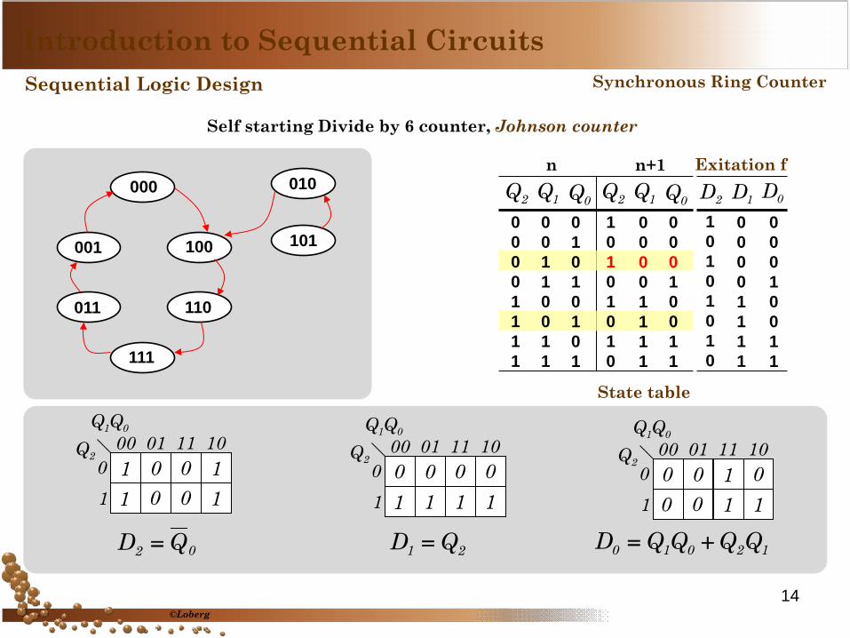
Self starting Divide by 6 counter, Johnson counter
0Q2Q 1Q 0Q2Q 1Qn n+1
State table
0 0 0 0 1 1 1 1
0 0 1 1 0 0 1 1
0 1 0 1 0 1 0 1
1 0 1 0 1 0 1 0
0 0 0 0 1 1 1 1
0 0 0 1 0 0 1 1
1 0 1 0 1 0 1 0
0 0 0 0 1 1 1 1
0 0 0 1 0 0 1 1
2D 1D 0DExitation f
11
0 1100
000 01 11 10
01
01QQ
2Q
02 QD =
01
0 0111
000 01 11 10
01
01QQ
2Q
21 QD =
00
1 0110
000 01 11 10
01
01QQ
2Q
12010 QQQQD +=
©Loberg
Introduction to Sequential Circuits Sequential Logic Design Synchronous Ring Counter
14

Self starting Divide by 6 counter, Johnson counter
CLOCK
0Q
D Q
QCCLR
PR
D Q
QCCLR
PR
D Q
QCCLR
PR
2Q 1Q
0CLEAR1CLEAR2CLEAR
0PR1PR0PR
0PRCLR ==
Q2
Q1
Q0
S0 S1 S2 S3 S4 S5 S0 S1 S2 S3
Timing diagram of 3-bit Johnson counter
©Loberg
Introduction to Sequential Circuits Sequential Logic Design Synchronous Ring Counter
15

Self-starting 4-bit Johnson counter
Timing diagram of 4-bit Johnson counter
Q0
Q1
Q2
S0 S1 S2 S3 S4 S5 S6 S7 S0 S1
Q3 (1) (0) (7) (3) (15) (14) (8) (12) (1)
©Loberg
Introduction to Sequential Circuits Sequential Logic Design Synchronous Ring Counter
16

23120130 QDQDQDQD ====
CLOCK
2Q
D Q
QCCLR
PR
D Q
QCCLR
PR
D Q
QCCLR
PR
0Q 1Q
CLEAR
D Q
QCCLR
PRPRESET
3Q
Exitation functions:
Is this a self-starting counter ?
©Loberg
Introduction to Sequential Circuits Sequential Logic Design Synchronous Ring Counter
17

23120130 QDQDQDQD ====Exitation functions:
0 0 0 0 0 0 0 0 1 1 1 1 1 1 1 1
0 0 0 0 1 1 1 1 0 0 0 0 1 1 1 1
0 0 1 1 0 0 1 1 0 0 1 1 0 0 1 1
0 1 0 1 0 1 0 1 0 1 0 1 0 1 0 1
0 1 2 3 4 5 6 7 8 9 10 11 12 13 14 15
2Q 0Q1Q3Q0 0 0 0 1 1 1 1 0 0 0 0 1 1 1 1
0 0 1 1 0 0 1 1 0 0 1 1 0 0 1 1
0 1 0 1 0 1 0 1 0 1 0 1 0 1 0 1
1 1 1 1 1 1 1 1 0 0 0 0 0 0 0 0
1D3D 0D2D1Q3Q 0Q2Q0 0 0 0 1 1 1 1 0 0 0 0 1 1 1 1
0 0 1 1 0 0 1 1 0 0 1 1 0 0 1 1
0 1 0 1 0 1 0 1 0 1 0 1 0 1 0 1
1 1 1 1 1 1 1 1 0 0 0 0 0 0 0 0
1 3 5 7 9 11 13 15 0 2 4 6 8 10 12 14
Exitation n n+1 0123 QQQQ
0 1 3
7
15 14 12
8
9 2 5
11
6 13 10
4
Not a self starting counter
©Loberg
Introduction to Sequential Circuits Sequential Logic Design Synchronous Ring Counter
18

0 1 3
7
15 14 12
8
9 2 5
11
6 13 10
4 0 0 0 0 0 0 0 0 1 1 1 1 1 1 1 1
0 0 0 0 1 1 1 1 0 0 0 0 1 1 1 1
0 0 1 1 0 0 1 1 0 0 1 1 0 0 1 1
0 1 0 1 0 1 0 1 0 1 0 1 0 1 0 1
0 1 2 3 4 5 6 7 8 9 10 11 12 13 14 15
2Q 0Q1Q3Q0 0 0 0 1 1 1 1 0 0 0 0 1 1 1 1
0 0 1 1 0 0 1 1 0 0 1 1 0 0 1 1
0 1 0 1 0 1 0 1 0 1 0 1 0 1 0 1
1 1 1 1 1 1 0 1 0 0 0 0 0 0 0 0
1D3D 0D2D1Q3Q 0Q2Q0 0 0 0 1 1 1 1 0 0 0 0 1 1 1 1
0 0 1 1 0 0 1 1 0 0 1 1 0 0 1 1
0 1 0 1 0 1 0 1 0 1 0 1 0 1 0 1
1 1 1 1 1 1 0 1 0 0 0 0 0 0 0 0
1 3 5 7 9 11 12 15 0 2 4 6 8 10 12 14
Exitation n n+1 We can modify the State Diagram
23 QD = 12 QD = 01 QD =
00
00 01 11 10
01
11
10
0P
7P5P 6P
1P 2P3P
4P
9P 10P11P
12P 13P 14P15P
8P
1 1 0 1
01QQ23QQ
1 1 1 1
( )01230 QQQQD ++=
Exitation functions :
Self starting counter
©Loberg
Introduction to Sequential Circuits Sequential Logic Design Synchronous Ring Counter
19

( )01230 QQQQD ++=
Self-starting 4-bit Johnson counter
CLOCK
2Q
D Q
QCCLR
PR
D Q
QCCLR
PR
D Q
QCCLR
PR
0Q 1Q
CLEAR
D Q
QCCLR
PRPRESET
3Q
In worst case, it takes maximum 8 clock cycles to jump back to the correct output sequence. We can modify state diagram to reduce it to the 1 clock cycle.
©Loberg
Introduction to Sequential Circuits Sequential Logic Design Synchronous Ring Counter
20

0 1
3
7
15 14
12
8
Others
State diagram
0123 QQQQ0 0 0 1 1 1 1 0 X
0 0 1 1 1 1 0 0 X
0 1 1 1 1 0 0 0 X
2Q 1Q 0Q0 0 1 1 1 1 0 0 0
0 1 1 1 1 0 0 0 0
1 1 1 1 0 0 0 0 0
2Q 1Q 0Q0 0 1 1 1 1 0 0 0
0 1 1 1 1 0 0 0 0
1 1 1 1 0 0 0 0 0
2D 1D 0Dn n+1 exitation f
3Q0 1 3 7 15 14 12 8 X
0 0 0 0 1 1 1 1 X
3Q0 0 0 1 1 1 1 0 0
0 0 0 1 1 1 1 0 0
3D
State Table for 4-bit Johnson counter
Self-starting 4-bit Johnson counter
Others
©Loberg
Introduction to Sequential Circuits Sequential Logic Design Synchronous Ring Counter
21

0 0 0 1 1 1 1 0 X
0 0 1 1 1 1 0 0 X
0 1 1 1 1 0 0 0 X
2Q 1Q 0Q0 0 1 1 1 1 0 0 0
0 1 1 1 1 0 0 0 0
1 1 1 1 0 0 0 0 0
2Q 1Q 0Q0 0 1 1 1 1 0 0 0
0 1 1 1 1 0 0 0 0
1 1 1 1 0 0 0 0 0
2D 1D 0Dn n+1 exitation f
3Q0 1 3 7 15 14 12 8 X
0 0 0 0 1 1 1 1 X
3Q0 0 0 1 1 1 1 0 0
0 0 0 1 1 1 1 0 0
3D
State Table for 4-bit Johnson counter
0120233 QQQQQQD +=
1230132 QQQQQQD +=
0120231 QQQQQQD +=
0131230 QQQQQQD +=
Exitation Functions
00
00 01 11 10
01
11
10
0P
7P5P 6P
1P 2P3P
4P
9P 10P11P
12P 13P 14P15P
8P
1
1
01QQ23QQ
1 1
3D
00
00 01 11 10
01
11
10
0P
7P5P 6P
1P 2P3P
4P
9P 10P11P
12P 13P 14P15P
8P
1 1
01QQ23QQ
1
1 0D
©Loberg
Introduction to Sequential Circuits Sequential Logic Design Synchronous Ring Counter
Self-starting 4-bit Johnson counter
22

Exitation Functions :
23120130 QDQDQDQD ====
( )010323 QQQQQD +=
( )230312 QQQQQD +=
( )122301 QQQQQD +=
( )011230 QQQQQD +=
0 1
3
7
15 14
12
8
Others State diagram
True (1) during correct output sequence
0D0D0D0D 3210 ====False (0) on other states
Self-starting 4-bit Johnson counter
Others
©Loberg
Introduction to Sequential Circuits Sequential Logic Design Synchronous Ring Counter
23

24
The End