serie actuators nes sin previo aviso - aignep reserva-se o ... · aignep si riserva il diritto di...
TRANSCRIPT

Aig
nep
si ri
serv
a il
diri
tto
di v
aria
re m
odel
li e
ingo
mbr
i sen
za p
reav
viso
- Ai
gnep
rese
rves
the
right
to v
ary
mod
els a
nd d
imen
sion
s with
out n
otic
e - A
igne
p be
hält
sich
das
Rec
ht v
or, D
aten
ohn
e An
künd
igun
g zu
änd
ern
Ai
gnep
se ré
serv
e le
dro
it de
mod
ifier
les d
onné
es sa
ns p
réav
is -
Aig
nep
se re
serv
a el
der
echo
de
mod
ifica
r mod
elos
y d
imen
sion
es si
n pr
evio
avi
so -
Aign
ep re
serv
a-se
o d
ireito
de
alte
rar o
s mod
elos
e d
imen
sões
sem
pré
vio
avis
o
Seri
e A
ctua
torsATTUATORI PNEUMATICI
PNEUMATIC ACTUATORS PNEUMATISCHE ANTRIEBE
ACTIONNEURS PNEUMATIQUESACTUADORES NEUMÁTICOS
ATUADORES PNEUMÁTICOS

Serie GR01F/GR02F/GR03F GR04F/GR05F
Serie Actuators
Serie B
Cilindri Corsa Breve Short Stroke Cylinders Kurzhubzylinder Vérins à faible course Cilindros Carrera Corta Cilindros de curso Reduzido
Ø 12-100 mm
Serie X
Cilindro Cylinder Zylinder Vérins Cilindros Cilindros
ISO 15552 - Ø 32-125 mm
Serie Q Serie E
Cilindro Cylinder Zylinder Vérins Cilindros Cilindros
ISO 6431 - Ø 32-320 mm
Cilindri Compatti Compact Cylinder Kompaktzylinder Vérins compacts Cilindros Compactos Cilindros Compactos
Ø 12-100 mm
Serie Mini
MiniCilindri MiniCylinders Minizylinder Mini-vérins Minicilindros Mini-cilindros
ISO 6432 - Ø 8-25 mm
Serie Mini Inox
MiniCilindri Inox MiniCylinders Inox Minizylinder Inox Mini-vérins inox Minicilindros Inox Mini-cilindros Inox
ISO 6432 - Ø 16-25 mm
Serie A95
Cilindro A95 Cylinders A95 Zylinder A95 Vérins A95 Cilindros A95 Cilindros A95
Ø 32-63 mm
Serie CA - CAF
Cilindro a Cartuccia Cartridge Cylinders Einschraubzylinder Vérins cartouche Cilindros de cartucho Cilindro Plug
Ø 6-16 mm
Serie V
Cilindro INOX Cylinder INOX Zylinder INOX Vérins INOX Cilindros INOX Cilindros INOX
ISO 15552 - Ø 32-125 mm
Serie NHA
Cilindro Steli Gemellati Twin piston rod Cylinders Twin Kolbenstange Zylinder Vérins à deux tiges Cilindros de vástagos gemelos Cilindro de haste dupla
ISO 15552 - Ø 32-100 mm
Serie W
Cilindri Compatti Compact Cylinder Kompaktzylinder Vérins compacts Cilindros Compactos Cilindros Compactos
ISO 21287 - Ø 20-100 mm
Serie P
Cilindri Compatti Compact Cylinder Kompaktzylinder Vérins compacts Cilindros Compactos Cilindros Compactos
Ø 125-250 mm
Accessori per Cilindri Accessories for Cylinders Befestigungselemente für Zylinder Accessoires pour Vérins Accesorios para Cilindros Accesorios para Cilindros
ISO 6431 - ISO 15552 - ISO 21287
Serie CG01 - CG02 Serie CG04
Unità di Guida Guide Units Führungseinheiten Unités de guidage Unidades de Guiado Guia para cilindros
ISO 15552 - Ø 12-25 mm ISO 6431 VDMA - Ø 32-100 mm
Cilindri con guida integrata Double-acting magnetic twin-guide cylindersZylinder mit integrierter führungVérins avec guide intégréCilindros con vástagos paralelosCilindros com haste dupla
Cilindro con tavola di scorrimento Slide cylinder Zylinder mit Schiebetisch Vérin avec table linéaire Cilindros guiados con mesa de deslizamiento Cilindros com mesa deslizante
Serie XR - RT01 - RT03S
Sensori Sensors Sensoren Capteurs Sensores Sensores
Cilindri Rotanti Rotary cylinders ISO 15552 Drehzylinder ISO 15552 Vérins rotatifs ISO 15552 Cilindros rotativos ISO 15552 Cilindros rotativos ISO 15552
Pinze pneumatiche Pneumatic gripper Pneumatische greifer Pince pneumatique Pinza neumática Garra pneumática
Serie R
Cilindri Senza Stelo Rodless Cylinder Kolbenstangenlose Zylinder Vérins Sans Tige Cilindro Neumático sin vástago Cilindro Pneumático sem haste
New New
New NewNewNew
New
SHOCKABSORBER
P A

Forze di spinta e tiro - Thrust and traction forces - Schub-und zugkräfte - Force de poussée et de traction - Fuerza de empuje y tracción - Força de avanço e recuo.
Valori compatibili per Serie X - E - V - P - N Compatible for Series X - E - V - P - N Kompatibel für die Serien X - E - V - P - N Compatible avec les Séries X - E - V - P - N Valores compatibles para Serie X - E - V - P - N Valores compatíveis para Séries X - E - V - P - N
Cilindro Cylinder Zyliner Vérins
Cilindro Cilindro
Stelo Rod
Stange Tige
Vástago Haste
Superficie utile Working Surface
Arbeitsfläche Surface de travail
Superfície útil Superfície útil
Pressione di lavoro Operating pressure
Betriebsdruck Pression de service Presión de trabajo
Pressão de operação
Ø Ø mm2 bar
1 2 3 4 5 6 7 8 9 10
Forza sviluppata Output force Zylinderkraft
Force du vérin Fuerza desarrollada Força desenvolvida
N
32 12S = 804 72 144 216 288 360 432 504 576 648 720
T = 691 62 124 186 248 310 372 434 496 558 620
40 16S = 1257 110 220 330 440 550 660 770 880 990 1100
T = 1056 95 190 285 380 475 570 665 760 855 950
50 20S = 1963 175 350 525 700 875 1050 1225 1400 1575 1750
T = 1649 148 296 444 592 740 888 1036 1184 1332 1480
63 20S = 3117 280 560 840 1120 1400 1680 1960 2240 2520 2800
T = 2803 250 500 750 1000 1250 1500 1750 2000 2250 2500
80 25S = 5027 450 900 1350 1800 2250 2700 3150 3600 4050 4500
T = 4536 405 810 1215 1620 2025 2430 2835 3240 3645 4050
100 25S = 7854 700 1400 2100 2800 3500 4200 4900 5650 6360 7000
T = 7363 660 1320 1980 2640 3300 3960 4620 5280 5940 6600
125 32S = 12270 1104 2208 3312 4416 5520 6624 7728 8832 9936 11040
T = 11468 1032 2064 3096 4128 5160 6192 7224 8256 9288 10320
160 40S = 20096 1774 3548 5322 7097 8871 10645 12419 14194 15968 17742
T = 18840 1663 3326 4990 6653 8316 9980 11643 13307 14970 16633
200 40S = 31440 2772 5544 8316 11089 13861 16633 19406 22178 24950 27723
T = 30144 2661 5322 7984 10645 13307 15968 18629 21291 23952 26614
250 50S = 48750 4331 8663 12995 17326 21658 25990 30322 34653 38985 43317
T = 46800 4158 8316 12475 16663 20792 24950 29109 33267 37426 41584
320 63S = 78872 7097 14194 21291 28388 35485 42582 49679 56776 63873 70971
T = 76776 6822 13644 20466 27288 34110 40932 47754 54576 61398 68220
S Spinta Thrust Schub Poussée Empuje Avanço
T Trazione Traction Zugkraft Traction Tracción Recuo
FORZE E CONSUMI FORCES AND CONSUMPTIONS KRÄFTE UND LUFTVERBRAUCH FORCES ET CONSOMMATIONS D’AIR FUERZAS Y CONSUMOS FORÇAS E CONSUMOS
18.3
Serie X - E - V - P - N

S Spinta Thrust Schub Poussée Empuje Avanço
T Trazione Traction Zugkraft Traction Tracción Recuo
Consumi cilindro - Cylinder air consumption - Zylinder Luftverbrauch - Consommation d’air des vérins - Consumo cilindro - Consumo de ar do cilindro.
Cilindro Cylinder Zyliner Vérins
Cilindro Cilindro
Carico molla Load spring
Federbelastung Charge du ressort
Carga Muelle Força da Mola
Corsa Stroke
Hub Course Carrera Curso
Ø 25 50 75 80 100Forza sviluppata
Output force Zylinderkraft
Force du vérin Fuerza desarrollada Força desenvolvida
N
32R 50 41 33 31,5 24,5
C 58 58 58 58 58
40R 52 43 34 32 25
C 61 61 61 61 61
50R 92 77 64 60 49
C 110 110 110 110 110
63R 92 77 64 60 49
C 110 110 110 110 110
80R 117 98 79 75 59
C 138 138 138 138 138
100R 117 98 79 75 59
C 138 138 138 138 138
R Carico Molla a Riposo Load of spring at rest Feder in Ruhestellung Ressort en position neutre Carga Muelle en Reposo Força da Mola em Repouso
C Carico Molla Compressa Load of compressed spring Feder komprimiert Ressort comprimé Carga Muelle Comprimido Força da Mola Comprimida
Cilindro Cylinder Zyliner Vérins
Cilindro Cilindro
Stelo Rod
Stange Tige
Vástago Haste
Superficie utile Working Surface
Arbeitsfläche Surface de travail
Superfície útil Superfície útil
Pressione di lavoro Operating pressure
Betriebsdruck Pression de service Presión de trabajo
Pressão de operação
Ø Ø mm2 bar
1 2 3 4 5 6 7 8 9 10Consumo aria per ogni 10 mm di corsa
Air consuption for each 10 mm of stroke Luftverbrauch pro 10 mm Hub
Consommation d’air par 10 mm de course Consumo aire para cada 10 mm de carrera Consumo de ar para cada 10 mm de curso
Nl
32 12S = 804 0,016 0,024 0,032 0,040 0,048 0,056 0,064 0,072 0,080 0,088
T = 691 0,014 0,021 0,028 0,035 0,041 0,048 0,055 0,062 0,069 0,076
40 16S = 1257 0,025 0,038 0,050 0,063 0,075 0,088 0,101 0,113 0,126 0,138
T = 1056 0,021 0,032 0,042 0,053 0,063 0,074 0,084 0,095 0,106 0,116
50 20S = 1963 0,039 0,059 0,079 0,098 0,118 0,137 0,157 0,177 0,196 0,216
T = 1649 0,033 0,049 0,066 0,082 0,099 0,115 0,132 0,148 0,165 0,181
63 20S = 3117 0,062 0,094 0,125 0,156 0,187 0,218 0,249 0,281 0,312 0,343
T = 2803 0,056 0,084 0,112 0,140 0,168 0,196 0,224 0,252 0,280 0,308
80 25S = 5027 0,101 0,151 0,201 0,251 0,302 0,352 0,402 0,452 0,503 0,553
T = 4536 0,091 0,136 0,181 0,227 0,272 0,318 0,363 0,408 0,454 0,499
100 25S = 7854 0,157 0,236 0,314 0,393 0,471 0,550 0,628 0,707 0,785 0,864
T = 7363 0,147 0,221 0,295 0,368 0,442 0,515 0,589 0,663 0,736 0,810
125 32S = 12270 0,245 0,368 0,491 0,614 0,736 0,859 0,982 1,104 1,227 1,350
T = 11468 0,229 0,344 0,459 0,573 0,688 0,803 0,917 1,032 1,147 1,261
160 40S = 20096 0,402 0,603 0,804 1,005 1,206 1,407 1,608 1,809 2,010 2,211
T = 18840 0,377 0,565 0,754 0,942 1,130 1,319 1,507 1,1696 1,884 2,072
200 40S = 31440 0,628 0,942 1,256 1,570 1,884 2,198 2,512 2,826 3,140 3,454
T = 30144 0,603 0,904 1,206 1,507 1,809 2,110 2,412 2,713 3,014 3,316
250 50S = 48750 0,981 1,472 1,963 2,453 2,948 3,434 3,925 4,415 4,906 5,400
T = 46800 0,942 1,413 1,884 2,355 2,826 3,297 3,768 4,239 4,710 5,181
320 63S = 78872 1,610 2,411 3,215 4,020 4,820 5,626 6,430 7,234 8,038 8,843
T = 76776 1,545 2,320 3,100 3,863 4,630 5,408 6,181 6,954 7,726 8,450
18.4
Serie X - E - V - P - N

SERIE NHA - CILINDRI A STELI GEMELLATI ISO 15552TWIN PISTON ROD CYLINDER ISO 15552
ZYLINDER MIT ZWEI STANGENFÜHRUNG ISO 15552 VÉRINS À DEUX TIGES ISO 15552
CILINDROS DE VÁSTAGOS GEMELOS ISO 15552CILINDROS DE HASTE DUPLA ISO 15552
CARATTERISTICHE TECNICHE TECHNICAL CHARACTERISTICS TECHNISCHE ANGABEN CARACTÉRISTIQUES TECHNIQUES CARACTERÍSTICAS TÉCNICAS CARACTERÍSTICAS TÉCNICAS
PTESFR
DEGBITMateriali e Componenti
1 Vite a brugola in acciao zincato2 Flangia in alluminio anodizzato 3 Steli in Acciaio cromato o Acciaio inox4 Guarnizione steli in Poliuretano 5 Spillo ammortizzatore in Acciaio zincato 6 O-ring in NBR 7 Anello elastico in Acciaio8 Boccole in acciaio teflonato PTFE9 Guarnizione ammortizzatore in Poliuretano10 Cono ammortizzatore in ottone11 O-ring in NBR 12 Vite a brugola in acciao zincato13 Magnete in Plastoferrite 14 Pistone anteriore in Alluminio 15 Guarnizione pistone in Poliuretano16 Pistone posteriore in resina acetalica 17 O-ring in NBR 18 Grano in acciaio 19 Dado in acciaio zincato 20 Guarnizione ammortizzatore in Poliuretano21 Testata Posteriore in Alluminio Pressofuso 22 Vite di fissaggio in acciao zincato23 Camicia in Alluminio anodizzato 24 Testata Anteriore in Alluminio Pressofuso
Matériaux et Composants
1 Vis en acier galvanisé2 Bride en aluminium anodisé3 Tige en acier chromé ou acier inoxydable4 Joint de tige en polyuréthane5 Vis de réglage d’amortisseur en acier galvanisé6 Joint torique en NBR7 Rondelle en acier8 Palier en PTFE 9 Joint d’amortisseur en polyuréthane10 Cône en laiton11 Joint torique en NBR12 Vis en acier galvanisé13 Aimants en plastoferrite 14 Flasque avant du piston en aluminium15 Joint de piston en polyuréthane16 Flasque arrière du piston en résine acetal17 Joint torique en NBR18 Vis en acier19 Ecrou en acier galvanisé20 Joint d’amortisseur en polyuréthane21 Flasque en aluminium22 Vis en acier galvanisé23 Profil en aluminium anodisé24 Tête en aluminium coulé
Component Parts and Materials
1 Fixing screw Galvanized steel2 Anodized Aluminium Flange3 Rods Chromium plated steel or Stainless steel4 Rod seal in Polyurethane5 Cushioning screw Galvanized steel6 O-ring NBR7 Elastic ring made in steel8 Steel with PTFE Bearing9 Cushioning seal in Polyurethane10 Brass cushioning cone11 O-ring NBR12 Fixing screw Galvanized steel13 Magnet Bonded ferrite14 Aluminium Front Piston15 Piston seal in Polyurethane16 Acetal resin rear Piston17 O-ring NBR18 Steel Grub screw19 Galvanized steel nut20 Cushioning seal in Polyurethane21 Rear head Die-casted aluminium22 Fixing screw Galvanized steel23 Tube Anodized aluminium 24 Front head Die-casted aluminium
Materiales y componentes
1 Tornillos allen en acero zincado 2 Brida en aluminio anodizado 3 Vástagos en Acero cromado o Acero inox4 Junta vástagos en Poliuretano 5 Tornillo amortiguador en Acero zincado 6 Junta tórica en NBR 7 Anillo elástico en Acero8 Cojinetes en acero teflonato PTFE9 Junta amortiguador en Poliuretano10 Cono amortiguador en latón11 Junta tórica en NBR 12 Tornillos allen en acciao zincado13 Magnete en Plastoferrita 14 Pistón anterior en Aluminio 15 Junta pistón en Poliuretano16 Pistón posterior en resina acetálica 17 Junta tórica en NBR 18 Tornillo en acero 19 Tuerca en acero zincado 20 Junta amortiguador en Poliuretano21 Tapa Posterior en Aluminio Presofundido 22 Tornillos de fijación en acero zincado23 Camisa en Aluminio anodizado 24 Tapa Anterior en Aluminio Presofundido
Komponenten und Materialien
1 Inbusschrauben Stahl verzinkt2 Flansch Aluminium eloxiert 3 Stange Stahl verchromt oder Edelstahl4 Stangendichtung aus Polyurethan5 Dämpfungsschraube Stahl verzinkt 6 O-Ring Dichtung aus NBR7 Sicherungsring Stahl8 Stahlbuchse Teflon beschichtet PTFE 9 Dämpfungsdichtung aus Polyurethan10 Stosskegel Messing 11 O-Ring Dichtung aus NBR 12 Inbusschrauben Stahl verzinkt13 Magnetring Plastoferrit 14 Vorderer Kolbenflansch Aluminium 15 Kolbenstangendichtung aus Polyurethan16 Hinterer Kolbenflansch aus Acetal 17 O-Ring Dichtung aus NBR 18 Schraube Stahl19 Stahlmutter verzinkt 20 Dämpfungsdichtung aus Polyurethan21 Zylinderdeckel Aluminium Druckguss22 Flanschschrauben Stahl verzinkt23 Zylinderrohr Aluminium eloxiert 24 Kopf aus Alu-Druckguss
Materiais e Componentes
1 Parafuso de fixação em Aço Zincado2 Flange em alumínio anodizado 3 Haste em Aço Cromado ou Aço Inox4 Vedação da haste em Poliuretano 5 Parafuso de Regulagem do Amortecimento em Aço Zincado 6 O-ring em NBR 7 Anel elástico em Aço8 Rolamento de Aço e PTFE9 Vedação do amortecimento em Poliuretano10 Cone de Amortecimento em Latão11 O-ring em NBR 12 Parafuso de fixação em Aço Zincado13 Imã em plastoferrite 14 Êmbolo dianteiro em alumínio 15 Vedação do êmbolo em poliuretano16 Êmbolo traseiro em resina acetálica 17 O-ring em NBR 18 Pino Roscado em Aço 19 Porca em aço zincado 20 Vedação do amortecimento em Poliuretano21 Cabeçote traseiro em Alluminio Fundido 22 Parafusos de fixação em aço zincado23 Camisa em Alumínio anodizado 24 Cabeçote Frontal em Alumínio Fundido
18.5
Serie NHA

Norma di Riferimento
Reference standard
Entspricht der Norm
Norme de référence
Normativa de referencia
Norma de referência
1907/2006 2011/65/CE PED 2014/68/UE
SILICON FREE
ATEX 2014/34/UE
Alesaggi
Bores
Durchmesser
Diamètres
Diámetros
Diâmetros
from 25 to 500 mm
Corse Standard
Standard Strokes
Standardhub
Courses standards
Carreras Standard
Cursos Padrão
FunzionamentoDoppio effetto ammortizzato magnetico. Stelo singolo e passante ammortizzato magnetico.
FunctioningDouble-acting cushioned magnetic.Single or through piston rod magnetic.
FunktionEinfach- und doppeltwirkend Dämpfung-Magnetisch Einseitig- oder durchgehende Kolbenstange.
ExécutionsDouble effet Amortisseurs Magnétique. Tige simple ou traversante Amortisseurs Magnétique.
FuncionamientoDoble efecto amortiguado magnético. Vástago simple o pasante amortiguado magnético.
FuncionamentoDupla Ação Magnético com Amortecimento. Haste simples e passante Magnético com Amortecimento.
1 bar (0.1 MPa)
10 bar (1 MPa)
Pressioni
Pressures
Druckbereich
Pressions
Presiones
Pressões
Bar Fluidi compatibiliAria compressa filtrata lubrificata e non lubrificata.
FluidsFiltered and lubricated compressed air as well as non lubricated air.
Geeignete MedienFiltered and lubricated compressed air as well as non lubricated air.
Fluides compatiblesAir comprimé filtré, lubrifié ou non lubrifié.
Fluidos compatiblesAire comprimido filtrado lubricado y no lubricado.
Fluidos compatíveisAr comprimido filtrado e lubrificado ou não lubrificado.
0 °C (-20 °C con aria secca) (-20 °C with dry air) (-20 °C mit trockener Luft) (-20 °C avec air sec) (-20 °C con aire seco) (-20 °C com ar seco)
+ 80 °C
Temperature
Temperatures
Temperatur
Températures
Temperaturas
Temperaturas
Corse a richiesta.Strokes on Demand.Auf Anfrage. Course sur demande.Carreras bajo Demanda.Cursos sob encomenda.
32 - 40 - 50 - 63 - 80 - 100 mm
18.6
Serie NHA

Forze di spinta e tiro - Thrust and traction forces - Schub-und zugkräfte - Force de poussée et de traction - Fuerza de empuje y tracción - Força de avanço e recuo.
Cilindro Cylinder Zyliner Vérins
Cilindro Cilindro
Stelo Rod
Stange Tige
Vástago Haste
Area steli Rod surface
Kolbenstangenoberfläche Rod surface
Superficie vástago Área vástago
Superficie utile Working Surface
Arbeitsfläche Surface de travail
Superfície útil Superfície útil
Pressione di lavoro Operating pressure
Betriebsdruck Pression de service Presión de trabajo
Pressão de operação
Ø Ø mm2 mm2 bar
1 2 3 4
Forza sviluppata Output force Zylinderkraft
Force du vérin Fuerza desarrollada Força desenvolvida
N
32 8 100,48S = 804 72 144 215 287
T = 703,52 54 108 161 215
40 10 157S = 1257 110 220 330 440
T = 1100 84 168 252 336
50 12 226,08S = 1963 175 350 526 701
T = 1736,92 135 270 404 539
63 16 401,92S = 3117 280 560 840 1120
T = 2715,08 206 413 619 826
80 20 628S = 5027 450 900 1350 1800
T = 4399 336 673 1009 1345
100 20 628S = 7854 700 1400 2100 2800
T = 7226 589 1177 1766 2355
S Spinta Thrust Schub Poussée Empuje Avanço
T Trazione Traction Zugkraft Traction Tracción Recuo
FORZE E CONSUMI FORCES AND CONSUMPTIONS KRÄFTE UND LUFTVERBRAUCH FORCES ET CONSOMMATIONS D’AIR FUERZAS Y CONSUMOS FORÇAS E CONSUMOS
Consumi cilindro - Cylinder air consumption - Zylinder Luftverbrauch - Consommation d’air des vérins - Consumo cilindro - Consumo de ar do cilindro.
Cilindro Cylinder Zyliner Vérins
Cilindro Cilindro
Stelo Rod
Stange Tige
Vástago Haste
Area steli Rod surface
Kolbenstangenoberfläche Rod surface
Superficie vástago Área vástago
Superficie utile Working Surface
Arbeitsfläche Surface de travail
Superfície útil Superfície útil
Pressione di lavoro Operating pressure
Betriebsdruck Pression de service Presión de trabajo
Pressão de operação
Ø Ø mm2 mm2 bar
1 2 3 4Consumo aria per ogni 10 mm di corsa
Air consuption for each 10 mm of stroke Luftverbrauch pro 10 mm Hub
Consommation d’air par 10 mm de course Consumo aire para cada 10 mm de carrera Consumo de ar para cada 10 mm de curso
Nl
32 8 100,48S = 804 0,016 0,032 0,048 0,064
T = 703,52 0,012 0,024 0,036 0,048
40 10 157S = 1257 0,025 0,050 0,075 0,100
T = 1100 0,019 0,038 0,057 0,075
50 12 226,08S = 1963 0,039 0,079 0,118 0,157
T = 1736,92 0,030 0,060 0,091 0,121
63 16 401,92S = 3117 0,062 0,125 0,187 0,249
T = 2715,08 0,046 0,092 0,139 0,185
80 20 628S = 5027 0,100 0,201 0,301 0,402
T = 4399 0,075 0,151 0,226 0,301
100 20 628S = 7854 0,157 0,314 0,471 0,628
T = 7226 0,132 0,264 0,396 0,528
S Spinta Thrust Schub Poussée Empuje Avanço
T Trazione Traction Zugkraft Traction Tracción Recuo
18.7
Serie NHA

Tabella dei codici di ordinazione
Ordering codes
Bestellschlüssel
Code de commande
Tabla de codificación para pedidos
Tabela de codificação para compra
NHA Doppio Effetto Ammortizzato Magnetico Double Acting Cushioned Magnetic Doppeltwirkend Dämpfung Magnetisch Double Effet Amortisseurs Magnétique Doble Efecto Amortiguado Magnético Dupla Ação Magnético Com Amortecimento
NLA Doppio effetto ammortizzato stelo passante magnetico Double acting double rod cushioned magnetic Doppeltwirkend Durchgehender Kolben Dämpfung Magnetischo Double Effet Tige Traversante Amortisseurs Magnétique Doble Efecto Vástago Pasante Amortiguado Magnético Dupla Ação Haste Passante Magnético com Amortecimento
NQA Doppio effetto stelo passante ammortizzato magnetico Double Acting cushioned magnetic with double rod end Doppeltwirkend Durchgehender Kolben Dämpfung Magnetisch Double Effet Tige Traversante Amortisseurs Magnétique Doble efecto vástago pasante amortiguado magnético Dupla ação stelo passante magnético com amortecimento
SERIEØ
mm
032040050063080100
0N 0 2A 2 0H 3 5
Corsa Stroke
Hub Course Carrera Curso
mm
00250050008001000125016002000250032003500400
A richiesta corse intermedie o superiori. Intermediate or higher strokes are available upon request.Auf Anfrage Zwischenhübe.Autres courses sur demande.Bajo demanda carreras intermedias o superiores.Cursos intermediários ou superiores sob encomenda.
G Camicia in alluminio profilo sagomato Anodized aluminium tube Mickey-mouse profile with slots Aluminiumprofil eloxiert mit Nuten Profil en aluminium anodisé avec rainures Camisa en aluminio perfil Mickey-mouse con ranuras Camisa de Alumínio com Perfil tipo Mickey-Mouse
IS Stelo inox Stainless steel rod Stange Edelstahl Tige en acier inoxydable Vástago inox Haste em Inox
G I S
Profilo Profile Rohr Tube Perfil Perfil
Varianti Choices
Varianten Options
Variantes Variações
Ø
mm
Corse - Strokes - Hub - Courses - Carreras - Cursos
mm
25 50 80 100 125 160 200 250 320 350 400 500
32
40
50
63
80
100
18.8
Serie NHA

NHADOPPIO EFFETTO AMMORTIZZATO MAGNETICO DOUBLE ACTING CUSHIONED MAGNETIC DOPPELTWIRKEND DÄMPFUNG MAGNETISCH DOUBLE EFFET AMORTISSEURS MAGNÉTIQUE DOBLE EFECTO AMORTIGUADO MAGNÉTICO DUPLA AÇÃO MAGNÉTICO COM AMORTECIMENTO
NLADOPPIO EFFETTO AMMORTIZZATO STELO PASSANTE MAGNETICO DOUBLE ACTING DOUBLE ROD CUSHIONED MAGNETIC DOPPELTWIRKEND DURCHGEHENDER KOLBEN DÄMPFUNG MAGNETISCH DOUBLE EFFET TIGE TRAVERSANTE AMORTISSEURS MAGNÉTIQUE DOBLE EFECTO VÁSTAGO PASANTE AMORTIGUADO MAGNÉTICO DUPLA AÇÃO HASTE PASSANTE MAGNÉTICO COM AMORTECIMENTO
TG
E
TG E
M M
K
ØB
PL VA EE
ØT
ØV
ØS
C
H F
EE
L3
L8 + stroke
Z
BG R
T �
�
�
Ø Ø Bd11 C E F H K M S T V Z F1 VA L2 WH ØMM SW KK L8 BG RT E TG EE PL L3 ZM
32 30 26 47 4 15 M6 9.5 35 8 32 18 48 4 20 26 12 10 M10X1.25 94 16 M6 47 32.5 G1/8 14 5 146
40 35 30 53 4 15 M8 11.25 45 10 40 22 54 4 22 30 16 13 M12X1.25 105 16 M6 53 38 G1/4 16 5 165
50 40 37 65 5 18 M8 15 55 12 50 26 69 4 28 37 20 17 M16X1.5 106 16 M8 65 46.5 G1/4 21 5 180
63 45 37 75 5 22 M10 19 70 16 63 35 69 4 28 37 20 17 M16X1.5 121 16 M8 75 56.5 G3/8 22 5 195
80 45 46 95 5 22 M12 25 85 20 80 40 86 4 34 46 25 22 M20X1.5 128 18 M10 95 72 G3/8 23 6 220
100 55 51 115 5 22 M12 35 105 20 100 50 91 4 38 51.5 25 22 M20X1.5 138 18 M10 115 89 G1/2 26 6 240
TG
E
TG E
M M
K
ØT
ØV
ØS
C
H F
EE
L3
Z
L8+ stroke
L2
F1 + stroke
A
KK
ØB
ØMM
BG
RT
SW SW1
�
�
�
Ø A Ø Bd11 C E F H K M S T V Z F1 VA L2 WH ØMM SW KK L8 BG RT E TG EE PL L3 ZM
32 22 30 26 47 4 15 M6 9.5 35 8 32 18 48 4 20 26 12 10 M10X1.25 94 16 M6 47 32.5 G1/8 14 5 146
40 24 35 30 53 4 15 M8 11.25 45 10 40 22 54 4 22 30 16 13 M12X1.25 105 16 M6 53 38 G1/4 16 5 165
50 32 40 37 65 5 18 M8 15 55 12 50 26 69 4 28 37 20 17 M16X1.5 106 16 M8 65 46.5 G1/4 21 5 180
63 32 45 37 75 5 22 M10 19 70 16 63 35 69 4 28 37 20 17 M16X1.5 121 16 M8 75 56.5 G3/8 22 5 195
80 40 45 46 95 5 22 M12 25 85 20 80 40 86 4 34 46 25 22 M20X1.5 128 18 M10 95 72 G3/8 23 6 220
100 40 55 51 115 5 22 M12 35 105 20 100 50 91 4 38 51.5 25 22 M20X1.5 138 18 M10 115 89 G1/2 26 6 240
LEGENDA KEY
LEGENDE LEGENDE LEYENDA LEGENDA
= Vite ad esagono incassato con filetto femmina per montaggio degli elementi di fissaggio S e per il montaggio diretto Socket head screw with female thread for mounting attachments Einbaubuchse für Gewindebefestigungen Embase taraudée pour le montage de fixations Tornillos con hexagono interior con rosca hembra para el montaje de los elementos de fijación y para el montaje directo Parafuso com sextavado interno e rosca fêmea para montagem dos elementos de fixação S e para montagem direta
= Viti per la regolazione dei deceleratori Regulating screw for adjustable end-position cushioning Einstellschraube für die Endlagendämpfung Vis de régulation pour fin de course réglable et amortis. Tornillos para la regulación de la amortiguación Parafusos para a regulagem do amortecimento pneumático
= Scanalatura per montaggio sensore Slot for proximity sensor Nuten für die Montage von magnetischen Sensoren Fente pour la fixation de capteur de proximité Ranura para montaje sensores Ranhura para montagem do sensor
18.9
Serie NHA

NQADOPPIO EFFETTO AMMORTIZZATO STELI PASSANTI MAGNETICO DOUBLE ACTING CUSHIONED MAGNETIC WITH DOUBLE RODS END DOPPELTWIRKEND DURCHGEHENDER KOLBEN DÄMPFUNG MAGNETISCH DOUBLE EFFET TIGE TRAVERSANTE AMORTISSEURS MAGNÉTIQUE DOBLE EFECTO VÁSTAGO PASANTE AMORTIGUADO MAGNÉTICO DUPLA AÇÃO STELO PASSANTE MAGNÉTICO COM AMORTECIMENTO
TG
E
TG E
M M
K
ØT
ØV
ØS
C
H F
EE
L3
L8 + stroke
Z
C + stroke
BG
RT
�
�
�
Ø Ø Bd11 C E F H K M S T V Z F1 VA L2 WH ØMM SW KK L8 BG RT E TG EE PL L3 ZM
32 30 26 47 4 15 M6 9.5 35 8 32 18 48 4 20 26 12 10 M10X1.25 94 16 M6 47 32.5 G1/8 14 5 146
40 35 30 53 4 15 M8 11.25 45 10 40 22 54 4 22 30 16 13 M12X1.25 105 16 M6 53 38 G1/4 16 5 165
50 40 37 65 5 18 M8 15 55 12 50 26 69 4 28 37 20 17 M16X1.5 106 16 M8 65 46.5 G1/4 21 5 180
63 45 37 75 5 22 M10 19 70 16 63 35 69 4 28 37 20 17 M16X1.5 121 16 M8 75 56.5 G3/8 22 5 195
80 45 46 95 5 22 M12 25 85 20 80 40 86 4 34 46 25 22 M20X1.5 128 18 M10 95 72 G3/8 23 6 220
100 55 51 115 5 22 M12 35 105 20 100 50 91 4 38 51.5 25 22 M20X1.5 138 18 M10 115 89 G1/2 26 6 240
GRAFICI CILINDRI NHA CHARTS NHA CYLINDERS ZYLINDERDIAGRAMME NHA VÉRINS NHA GRÁFICO CILINDROS NHA GRÁFICOS DOS CILINDROS SÉRIE NHA
Momento Flettente
Flexion Moment
Biegemoment
Moment de flexion
Momento Flexor
Momento Fletor
Momento Torcente
Torsion Moment
Drehmoment
Moment de torsion
Momento de Torsión
Momento Torsor
NCarico massimo Max admitted loadMax. BelastungMax. ChargeMax carga admisibleCarga máxima
mmCorsaStrokeHubCourseCarreraCurso
mm
N N
mm
18.10
Serie NHA
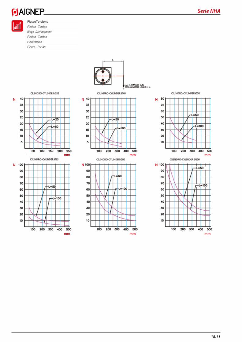
FlessoTorsione
Flexion - Torsion
Biege- Drehmoment
Flexion - Torsion
Flexotorsión
Flexão - Torsão
CORSA mm / STROKE mm CORSA mm / STROKE mm CORSA mm / STROKE mm
CORSA mm / STROKE mm CORSA mm / STROKE mm CORSA mm / STROKE mm
CORSA mm / STROKE mm CORSA mm / STROKE mm
CARI
CO
CARI
CO
CARI
CO
CARI
CO
CARI
CO
CARI
CO
CARICO
MA
X CA
RICO
AM
MIS
SIBI
LE
MA
X CA
RICO
AM
MIS
SIBI
LEmm
mm
mm
mm
mm
mm
N
N
N
N
N
N
18.11
Serie NHA

PTESFR
DEGBITDirettiva 2014/34/UE (ATEX)
I cilindri pneumatici a Cartuccia, Mini Cilindri ISO 6432, Mini Cilindri Inox, A95, COMPATTI (Q - W), Corsa Breve (B), Serie X ISO 15552, Serie E ISO 6431, a Steli Gemellati Serie NHA ISO 15552 e Serie P ISO 15552 presentano le seguenti caratteristiche:
II 2 GD c T6 -20°C<Tamb<80°C
II 2 GD: apparecchiatura per impianti di superficie (II = apparecchiature da non utilizzare in miniere) con presenza di gas, vapori o polveri, di categoria 2 (attrezzatura con un livello di sicurezza elevato in quanto non presenta pericoli di esplosione anche in presenza di un guasto prevedibile; può essere impiegata in aree con probabilità di presenza di atmosfere esplosive).
c: l’attrezzatura è costruttivamente sicura
T6 -20°C<Tamb<80°C: classe di temperatura superficiale e marcatura supplementare per T ambiente di utilizzo.
Directive 2014/34/UE (ATEX)
Les vérins pneumatiques: Cartouche, Mini Vérins ISO 6432, Mini-Vérins Inox, A95, COMPACTS, Q - W,Faible course (B), Série X ISO 15552, Série È ISO 6431, Bi Tiges Séries NHA ISO 15552 et Série P ISO 15552 présentent les caractéristiques suivantes:
II 2 GD c T6 -20°C<Tamb<80°C
II 2 GD: Dispositif pour installations en surface, (II = appareillages à ne pas utiliser dans l’extraction minière) avec présence de gaz, vapeurs ou poussières, de catégorie 2, (Equipement avec niveau de sécurité élevé puisqu’il ne présente pas de danger d’explosion, même en cas de dégât; il peut être utilisé dans des zonesavec des environnements explosifs possibles).
c: L’équipement est sûr de manière constructive
T6-20°C/Temp/80°C : Classe de température en surface et marquage supplémentaire par T pour l’environnement T d’utilisation.
Directive 2014/34/UE (ATEX)
The Pneumatic Cylinders: Cartridge, Mini Cylinders ISO 6432, Stainless steel Mini Cylinders, A95, Compact (Q - W), Short Stroke (B), Serie X ISO 15552, Serie E ISO 6431, Twin-piston rod Serie NHA ISO 15552 and Serie P ISO 15552 show the following features:
II 2 GD c T6 -20°C<Tamb<80°C
II 2 GD: Device for surface installations (II = do not use device in mining) with presence of gas, vapors of powders of category 2 (equipment with high safety factor since it excludes danger of explosion, even in case of damage; it can be used in areas with possible explosive environments).
c: Devices are constructively safe
T6 – 20ºC<Tamb<80ºC: Surface temperature class and additional marking for T usage environment.
Directiva 2014/34/UE (ATEX)
Los cilindros neumáticos de cartucho, Mini Cilindros ISO 6432, Mini Cilindros Inox, A95, COMPACTOS (Q-W), Carrera corta (B), Serie X ISO 15552, Serie E ISO 6431, de vástagos gemelos Serie NHA ISO 15552 y Serie P ISO 15552 presentan las siguientes características:
II 2 GD c T6 -20°C<Tamb<80°C
II 2 GD: Equipos para instalaciones de superficie (II = Equipos de no utilizar en minas) con presencia de gas, vapores o polvo, de categoría 2 (Equipos con un nivel de seguridad elevado en cuando no presentan peligro de explosión y en presencia de un fracaso previsible; pueden ser utilizadas en áreas con probabilidad de presencia de atmosferas explosivas).
c: El equipo es constructivamente seguro
T6 – 20ºC<Tamb<80ºC: clase de temperatura superficial y marcado suplementario para T ambiente de utilización.
Richtlinie 2014/34/UE (ATEX)
Pneumatik-Zylinder mit Kartusche, Mini Zylinder ISO 6432, Edelstahl Mini Zylinder, A95, Kompakte (Q – W), mit Kurzhub (B), Serie X ISO 15552, Serie E ISO 6431, mit Zweistangenführung Serie NHA ISO 15552 und Serie P ISO 15552 weisen folgende Merkmale auf:
II 2 GD c T6 -20°C<Tamb<80°C
II 2 GD: Vorrichtung für Oberflächeninstallation (II = verwenden Sie das Bauteil nicht im Bergbau) mit Vorhandensein von Gas, Dämpfen von Pulvern der Kategorie 2 (Geräte mit hohem Sicherheitsfaktor, da es Explosionsgefahr ausschließt, sogar im Schadenfall kann es in explosionsgefährlichen Umgebungen eingesetzt werden).
c: die Geräte sind konstruktiv sicher
T6 -20°C<Tamb<80°C: Oberflächentemperaturklasse und zusätzliche Kennzeichnung für T Nutzungsumgebung
Direttva 2014/34/UE (ATEX)
Os cilindros pneumáticos tipo Cartucho, Mini Cilindros ISO 6432, Mini Cilindros Inox, A95, COMPACTOS (Q - W), Curso Curto (B), Série X ISO 15552, Série E ISO 6431, com Haste Dupla Série NHA ISO 15552 e Série P ISO 15552 apresentam as seguintes características:
II 2 GD c T6 -20°C<Tamb<80°C
II 2 GD: equipamentos para instalações de superfície (II = equipamento não deve ser usado em minas), com a presença de gases, vapores ou pós, de categoria 2 (equipamento com um elevado nível de segurança porque não apresenta qualquer perigo de explosão, mesmo na presença de uma falha previsível; pode ser usado em áreas com probabilidade de atmosferas explosivas).
c: o equipamento é estruturalmente seguro
T6 -20 ° C <Tamb <C 80 °: classe de temperatura de superfície e marcação suplementar para o ambiente de utilização.
ISTRUZIONI E CERTIFICATO CONSULTARE:SEE INSTRUCTIONS AND CERTIFICATE AT:FÜR ANLEITUNGEN UND ZERTIFIKAT BESUCHEN SIE: POUR INSTRUCTIONS ET CERTIFICAT VISITER:INSTRUCCIONES Y CERTIFICADO CONSULTAR:INSTRUÇÕES E CERTIFICADO, CONSULTAR:
www.aignep.com
18.1
Serie Cylinders
