series 21-/22- 10-/11-cm2-z air cylinder 20, 25, 32, 40content2.smcetech.com/pdf/clean...
TRANSCRIPT

Cylinder stroke (mm)
NilSn
Number of auto switches
2 pcs.1 pc.n pcs.
Solid state
Auto switchM9B, M9BW
Reed switch A93
ø20, ø25, ø32, ø40Air Cylinder
How to Order
21 - C D M 2 L 40 - 150 A Z - M9BW
10 - C D M 2 L 40 - 150 A F Z - M9BW
Bore size (mm)
∗ Rubber bumper only
NilF
Male rod endFemale rod end
Rod end thread
10-/11-21-/22-Series CM2-Z
1011
Relief typeVacuum suction type
Clean series
Nil
Built-in magnetNo
D With auto switch(Built-in magnet)
BLFGBZFZ
MountingBasic (Double-side bossed)
Axial footRod flangeHead flange
Boss-cut, BasicBoss-cut, Rod flange
NilTNTF
Port thread typeRc
NPT∗
G∗2122
Relief typeVacuum suction type
Copper, fluorine andsilicone-free +Low particle generation Nil
A
CushionRubber bumper
Air cushion
Model
10-/21-CM22010-/21-CM22510-/21-CM23210-/21-CM24011-/22-CM22011-/22-CM22511-/22-CM23211-/22-CM240
Rel
ief
type
Vac
uum
suct
ion
type
Bore size(mm)
2025324020253240
Port size
1/8
1/4
1/4
Lubrication
Non-lubeDouble acting,
Single rod
Action Standard stroke(mm)
25, 50, 75, 100, 125,
150, 200, 250, 300
Auto switchmounting
CushionRubber Air
1/8
Model
Proof pressureMaximum operating pressureMinimum operating pressure
Ambient and fluid temperature
Piston speedStroke length tolerance
Cleanliness class (ISO class)
Grease
Mounting
20/25/32/40
1.5 MPa1.0 MPa
0.05 MPaWithout auto switch: –10°C to 70°C
With auto switch: –10°C to 60°C (No freezing)
+1.4
Basic/Axial foot/Rod flange/Head flange0
Bore size (mm)Item
10-/11-: 30 to 400 mm/s, 21-/22-: 50 to 400 mm/s
Specifications
10-/11-: Fluorine grease21-/22-: Lithium soap based grease
10-: Class 4, 21-: Class 511-/22-: Class 3
2Bore size Suction flow rate L/min (ANR)
20/25/32/40
Suction Flow Rate of Vacuum Suction Type (Reference values)
RoHS
700
Air
Pre
par
atio
nE
qu
ipm
ent
Pre
ssur
e C
ontr
olE
quip
men
tF
low
Co
ntr
ol
Eq
uip
men
tPr
essu
re S
witc
hes/
Pres
sure
Sen
sors
Dir
ecti
on
alC
on
tro
l Val
ves
Air
Gri
pp
ers
Mo
du
lar
F. R
.Fi
ttin
gs &
Tub
ing
Air
Cyl
ind
ers
Rot
ary
Act
uato
rs

Note 1) Lead wire length symbols: 0.5 m………Nil M9BW 1 m……… M M9BWM 3 m……… L M9BWL 5 m……… Z M9BWZ
Note 2) Auto switches marked with “” are produced upon receipt of order.Note 3) PLC: Programmable Logic Controller
Applicable loadLead wire length (m)
Relay,PLC
TypeLoad voltageWiring
(Output) 3 (L)1 (M)0.5 (Nil)Auto switch model
Band mountingDC AC
12 V24 V2-wire
Indicatorlight
Yes
Electricalentry
GrommetReed auto switch
5 (Z)
M9B
M9BW—5 V
12 V24 V2-wireYesGrommetSolid stateauto switch
——
A93100 V
Auto Switch Specifications (Refer to the WEB catalog for detailed specifications and auto switches not in the following table.)
Auto Switch Proper Mounting Position (Detection at Stroke End)
Note) The above-mentioned value is a guide for auto switch mounting positions for stroke end detection. When actually mounting the auto switch, adjust the position after confirming the operating state of the auto switch.
D-M9D-M9W
A and B are the dimensions from the end of the head cover/rod cover to the end of the auto switch.
A and B are the dimensions from the end of the head cover/rod cover to the end of the auto switch.
D-A9Reed auto switchSolid state auto switch
A
A≈Hs
22 B
≈Hs
16
24.5 B
16
Auto Switch Mounting HeightAuto switch
model
Bore size
20253240
Hs22.5
25
28.5
32.5
D-M9D-M9WD-A9
(mm)
Auto Switch Proper Mounting PositionAuto switch
model
Bore size A11
10
11.5
17.5
B 9.5
10
10.5
15.5
D-A9D-M9D-M9W
A 7
6
7.5
13.5
B 5.5
6
6.5
11.5
(mm)
20253240
Refer to page 889 for the applicable auto switch list.
Air Cylinder CM2-Z21-22-CM2-Z/10-
11-
701

With rubber bumper
20253240
Bore size
8 81213
A1
20202021
HM4 x 0.7M5 x 0.8M6 x 1
M8 x 1.25
MM 95 95 97125
ZZ(mm)Female Rod End
∗ When female thread is used, use a thin wrench when tightening the piston rod.
∗ When female thread is used, use a wash-er etc. to prevent the contact part at the rod end from being deformed depending on the material of the workpiece.
(mm)ZZSPIEDA
40322520
24222218
2119.519.515.5
1412108 20-0.033
46.537.533.528
75.55.55
M14 x 1.5M10 x 1.25M10 x 1.25M8 x 1.25
42.534.53024
M26 x 1.5M26 x 1.5M20 x 1.5
1/41/81/8
88646262
1541221201161/8
M32 x 2
0
26-0.0330
26-0.0330
32-0.0390
AL K
121086
KA MM NA NNG
161313
1188813
F
13.510.510.510.5FLBore size H2
888
10
H1
665
8
H
50454541
22171713B1
41323226B2
ø20, ø25
ø32, ø40
2 x
øE
h8
2 x NNG
M5 x 0.8(This drawing shows the cases of ø20 and ø25.)Relief port (10-, 21-)Vacuum port (11-, 22-)
2 x P(Rc, NPT, G)
GH2
Width across flats KA
øD
ZZ + Stroke
S + StrokeHF
1.5
FEffective thread length2 x FL
1.5
AAL
K
Standard port
Standard port
NA
NA
øI
45°
Female rod end
ZZ + StrokeH
3.5
Thread depth A1
Female thread MM
Relief port (10-, 21-)Vacuum port (11-, 22-)
H1Width across flats B1
Width across flats B2
MM
Relief port (10-, 21-)Vacuum port (11-, 22-)
Basic (Double-side Bossed) (B): CM2B, CM2B10-11-
21-22-
702
Air Cylinder CM2-Z21-22-CM2-Z/10-
11-
Air
Pre
par
atio
nE
qu
ipm
ent
Pre
ssur
e C
ontr
olE
quip
men
tF
low
Co
ntr
ol
Eq
uip
men
tPr
essu
re S
witc
hes/
Pres
sure
Sen
sors
Dir
ecti
on
alC
on
tro
l Val
ves
Air
Gri
pp
ers
Mo
du
lar
F. R
.Fi
ttin
gs &
Tub
ing
Air
Cyl
ind
ers
Rot
ary
Act
uato
rs

(mm)
20253240
Bore size
8 81213
A1
20202021
HM4 x 0.7M5 x 0.8M6 x 1
M8 x 1.25
MM113113115145
ZZ(mm)Female Rod End
WB13131316
WA31313136
26262631
GA88811
GB681012
KAFL10.510.510.513.5
134138140174
41454550
88810
5668
26323241
13171722
ZZH H2H1B2B1
808082
108
S1/81/81/81/4
PM20 x 1.5M26 x 1.5M26 x 1.5M32 x 2
NN2430
34.542.5
NAM8 x 1.25M10 x 1.25M10 x 1.25M14 x 1.5
MM5
5.55.57
K28
33.537.546.5
I6666
GC13131316
F0 20−0.0330 26−0.0330 26−0.0330 32−0.039
E8
101214
D15.519.519.521
AL18222224
A20253240
Bore size
ZZ + Stroke
S + Stroke F
1.5
Effective thread length2 x FL
1.5
HFA
ALKMM
øD
GCH2 GA
WA
Width across flats B1
H1
Width across flats KAWidth across flats B2
M5 x 0.8Relief port (10-, 21-)Vacuum port (11-, 22-)
2 x
øE
h8
2 x NNGBWB
NA
NA
Cushion needle(Width across flats 1.5)
45°
øI
2 x P(Rc)
Female rod end
H3.5
Thread depth A1
Female thread MM
ZZ + Stroke
With air cushion
Basic (Double-side Bossed) (B): CM2B, CM2B10-11-
21-22-
∗ When female thread is used, use a thin wrench when tightening the piston rod.
∗ When female thread is used, use a wash-er etc. to prevent the contact part at the rod end from being deformed depending on the material of the workpiece.
Air Cylinder CM2-Z21-22-CM2-Z/10-
11-
703

With air cushion
(mm)WB13131316
WA31313136
26262631
GA88811
GB681012
KAFL10.510.510.513.5
121125127158
41454550
88810
5668
26323241
13171722
ZZH H2H1B2B1
808082
108
S1/81/81/81/4
PM20 x 1.5M26 x 1.5M26 x 1.5M32 x 2
NN2430
34.542.5
NAM8 x 1.25M10 x 1.25M10 x 1.25M14 x 1.5
MM5
5.55.57
K28
33.537.546.5
I6666
GC13131316
F0 20−0.0330 26−0.0330 26−0.0330 32−0.039
E8
101214
D15.519.519.521
AL18222224
A20253240
Bore size
ZZ + Stroke
S + Stroke
1.5
HFA
ALKMM
øD
GCH2 GA
WA
H1
GBWB
NA
NA
Cushion needle(Width across flats 1.5)
45°
øI
2 x P(Rc)
øE
h8
NN
M5 x 0.8Relief port (10-, 21-)Vacuum port (11-, 22-)
∗ Refer to page 702 for female thread dimensions.
∗ Refer to page 703 for female thread dimensions.
(mm)ZZH H2H1 SPIGE�DA
40322520
24222218
2119.519.515.5
1412108 20-0.033
161313
1188
46.537.533.528
75.55.55
M14 x 1.5M10 x 1.25M10 x 1.25M8 x 1.25
42.534.53024
M26 x 1.5M26 x 1.5M20 x 1.5
1/41/81/8
88646262
22171713
41323226
665
888
50454541
138109107103
108
1/8
M32 x 2
8130
26-0.0330
26-0.0330
32-0.0390
AL F
13.510.510.510.5FL K
121086
KA MM NA NNB1 B2Bore size
ø20, ø25
ø32, ø40
Width across flats KA G
2 x P(Rc, NPT, G)
M5 x 0.8(This drawing shows the cases of ø20 and ø25.)Relief port (10-, 21-)Vacuum port (11-, 22-)
Effective thread length FL
GH2
NN
Width across flats B2
H1
MM
Width across flats B1
øD
ZZ + Stroke
S + StrokeHF
1.5
AAL
K
øE
h8
Standard port
Standard port
NA
NA
øI
45°
Relief port (10-, 21-)Vacuum port (11-, 22-)
Relief port (10-, 21-)Vacuum port (11-, 22-)
With rubber bumper
Boss-cut, Basic (BZ): CM2BZ, CM2BZ10-11-
21-22-
Width across flats KA
Effective thread length FLWidth across flats B2
Width across flats B1
Air Cylinder CM2-Z21-22-CM2-Z/10-
11-
704
Air
Pre
par
atio
nE
qu
ipm
ent
Pre
ssur
e C
ontr
olE
quip
men
tF
low
Co
ntr
ol
Eq
uip
men
tPr
essu
re S
witc
hes/
Pres
sure
Sen
sors
Dir
ecti
on
alC
on
tro
l Val
ves
Air
Gri
pp
ers
Mo
du
lar
F. R
.Fi
ttin
gs &
Tub
ing
Air
Cyl
ind
ers
Rot
ary
Act
uato
rs

With air cushion
ø20, ø25
ø32, ø40
(mm)
40474754
B120120122154
21252527
Z88810
Y20202023
X55555575
LZ40404055
LX3.23.23.23.2
LTLS25282830
LH6.86.86.87
LD4444
LC WB13131316
WA31313136
26262631
GA888
11
GB681012
KAFL10.510.510.513.5
149153155191
41454550
88810
5668
26323241
13171722
ZZH H2H1B2B1
808082108
S1/81/81/81/4
PM20 x 1.5M26 x 1.5M26 x 1.5M32 x 2
NN2430
34.542.5
NAM8 x 1.25M10 x 1.25M10 x 1.25M14 x 1.5
MM5
5.55.57
K28
33.537.546.5
I6666
GC13131316
F8
101214
D15.519.519.521
AL18222224
A20253240
Bore size
45°
Cushion needle(Width across flats 1.5)
BL
H
LZLX
2 x øLC
LTYX
øI
FGB
WB2 x P(Rc)
M5 x 0.8Relief port (10-, 21-)Vacuum port (11-, 22-)
GCGAWA
FH
H2
KMM
øD
H1
ALA
Width across flats B2 Width across flats NA
Width across flats KA
Width across flats B1
ZY X
ZZ + Stroke
LS + Stroke
S + Stroke
4 x øLD
(mm)H H2H1 SPIGDA
40322520
24222218
2119.519.515.5
1412108
161313
1188
46.537.533.528
75.55.55
M14 x 1.5M10 x 1.25M10 x 1.25M8 x 1.25
42.534.53024
M26 x 1.5M26 x 1.5M20 x 1.5
1/41/81/8
88646262
22171713
41323226
665
888
50454541
108
1/8
M32 x 2
813AL F
13.510.510.510.5FL K
121086
KA MM NA NNB1 B2Bore size
54474740B LH LTLS LXLD
444
76.86.8
55404040
75555555
104102102
3.23.23.2
30282825
3.2134
6.84LC LZ X Y
10888
27252521
202020
23
Z ZZ
171137135131
∗ The bracket is shipped together. ∗ Refer to page 702 for female thread dimensions.
∗ The bracket is shipped together. ∗ Refer to page 703 for female thread dimensions.
ZZ + Stroke
LS + Stroke
S + Stroke X YXYZ
LT
Width across flats B2
øD
MM
Width across flats B1
HGF
H2
KH1
ALA
2 x P(Rc, NPT, G)
M5 x 0.8(This drawing shows the cases of ø20 and ø25.)Relief port (10-, 21-)Vacuum port (11-, 22-)
Width across flats NA
2 x NN(Effective thread length 2 x FL)
G F
øI
4 x øLD
BL
H
Standard port
Standard port
2 x øLCLZLX
45°
Width across flats KA
Relief port (10-, 21-)Vacuum port (11-, 22-)
Relief port (10-, 21-)Vacuum port (11-, 22-)
With rubber bumper
2 x NN(Effective thread length 2 x FL)
Axial Foot (L): 10- 11-CM2L, 21-
22-CM2L
Air Cylinder CM2-Z21-22-CM2-Z/10-
11-
705

ø20 to ø32
ø40
With air cushion
(mm)
37414145
Z75757582
FZ———36
FY60606066
FX4445
FT7777
FD303737
47.3
C2
34404052
B WB13131316
WA31313136
26262631
GA88811
GB68
1012
KAFL10.510.510.513.5
134138140174
41454550
88810
5668
26323241
13171722
ZZH H2H1B2B1
808082
108
S1/81/81/81/4
PM20 x 1.5M26 x 1.5M26 x 1.5M32 x 2
NN2430
34.542.5
NAM8 x 1.25M10 x 1.25M10 x 1.25M14 x 1.5
MM5
5.55.57
K28
33.537.546.5
I6666
GC13131316
F 0 20−0.033 0 26−0.033 0 26−0.033 0 32−0.039
E8
101214
D15.519.519.521
AL18222224
A20253240
Bore size
C2
45°
45°
øI
2 x
øE
h8
WBGB
F1.5
2 x NN
ZZ + Stroke
S + Stroke
2 x P(Rc)
M5 x 0.8Relief port (10-, 21-)Vacuum port (11-, 22-)
WAGAGC
H2
H1
øD
HFTZ
KAAL
B
FZFX
2 x øFDMounting hole Cushion needle
(Width across flats 1.5)
Cushion needle(Width across flats 1.5)
FY
4 x øFDMounting hole
ø40
ø20 to ø32
MM
ZH H2H1 SPIFC2A
40322520
24222218
2119.519.515.5
47.3373730
141210
161313
46.537.533.528
FL
13.510.510.510.5
75.55.55
M14 x 1.5M10 x 1.25M10 x 1.25M8 x 1.25
42.534.53024
M26 x 1.5M26 x 1.5M20 x 1.5
1/41/81/8
88646262
22171713
41323226
665
888
50454541
45414137
108
1/8
M32 x 2
138AL D K
121086
KA MM NA NNB1 B2Bore size
52404034B FX FZFY GFT
777
544
11888
———
757575
66606060
8236
47FDE
20-0.0330
26-0.0330
26-0.0330
32-0.0390
ZZ
154122120116
(mm)
∗ The bracket is shipped together. ∗ Refer to page 702 for female thread dimensions.
∗ The bracket is shipped together. ∗ Refer to page 703 for female thread dimensions.
2 x NN
øI
øE
h8
G
ZZ + Stroke
S + Stroke
1.5
2 x P(Rc, NPT, G)
M5 x 0.8(This drawing shows the cases of ø20 and ø25.)Relief port (10-, 21-)Vacuum port (11-, 22-)
GH2
Width across flats B2
H1Width across flats B1
MM
øD
H
FTKAAL
Z
FZFX
B
Standard port2 x øFDRelief port (10-, 21-)Vacuum port (11-, 22-)(ø20, ø25)
Standard port 45°
FY
4 x øFD
F
C2
Width across flats KA
Width across flats NA
Effective thread length 2 x FL
Relief port (10-, 21-)Vacuum port (11-, 22-)(ø32,ø40)
With rubber bumper
Width across flats B2
Width across flats B1
Width across flats KA
Width across flats NA
Effective thread length 2 x FL
Rod Flange (F): 10- 11-CM2F, 21-
22-CM2F
Air Cylinder CM2-Z21-22-CM2-Z/10-
11-
706
Air
Pre
par
atio
nE
qu
ipm
ent
Pre
ssur
e C
ontr
olE
quip
men
tF
low
Co
ntr
ol
Eq
uip
men
tPr
essu
re S
witc
hes/
Pres
sure
Sen
sors
Dir
ecti
on
alC
on
tro
l Val
ves
Air
Gri
pp
ers
Mo
du
lar
F. R
.Fi
ttin
gs &
Tub
ing
Air
Cyl
ind
ers
Rot
ary
Act
uato
rs

With air cushion
ø20 to ø32
ø40
(mm)
125129131163
Z75757582
FZ———36
FY60606066
FX4445
FT7777
FD303737
47.3
C2
34404052
B WB13131316
WA31313136
26262631
GA88811
GB68
1012
KAFL10.510.510.513.5
134138140174
41454550
88810
5668
26323241
13171722
ZZH H2H1B2B1
808082108
S1/81/81/81/4
PM20 x 1.5M26 x 1.5M26 x 1.5M32 x 2
NN2430
34.542.5
NAM8 x 1.25M10 x 1.25M10 x 1.25M14 x 1.5
MM5
5.55.57
K28
33.537.546.5
I6666
GC13131316
F 0 20−0.033 0 26−0.033 0 26−0.033 0 32−0.039
E8
101214
D15.519.519.521
AL18222224
A20253240
Bore size
ZH H2H1 SPIFC2A
40322520
24222218
2119.519.515.5
47.3373730
141210
161313
46.537.533.528
FL
13.510.510.510.5
75.55.55
M14 x 1.5M10 x 1.25M10 x 1.25M8 x 1.25
42.534.53024
M26 x 1.5M26 x 1.5M20 x 1.5
1/41/81/8
88646262
22171713
41323226
665
888
50454541
143113111107
108
1/8
M32 x 2
138AL D K
121086
KA MM NA NNB1 B2Bore size
52404034B FX FZFY GFT
777
544
11888
———
757575
66606060
8236
47FDE
20-0.0330
26-0.0330
26-0.0330
32-0.0390
ZZ
154122120116
(mm)
øI
WBGB
Z + Stroke
ZZ + Stroke
S + Stroke
M5 x 0.8Relief port (10-, 21-)Vacuum port (11-, 22-)
WAGAGC
H2
H1
øD
HKA
AL
B
FZFX
FY
ø40
ø20 to ø32
FFT
2 x
øE
h8
1.5MM
45°
45°
C2
∗ The bracket is shipped together. ∗ Refer to page 702 for female thread dimensions.
∗ The bracket is shipped together. ∗ Refer to page 703 for female thread dimensions.
B
FZFXRelief port
(ø20, ø25)
øI
ZZ + Stroke
Z + Stroke
S + StrokeH
1.5
AAL
K
F
øD
øE
h8
G
H1
MM
2 x P(Rc, NPT, G)
FT
H2G
Relief port(ø32, ø40)
FY
45°
C2
With rubber bumper
Width across flats NA
Width across flats NA
Effective thread length 2 x FL
Effective thread length 2 x FL
2 x NN
2 x NN
Standard port2 x øFD
Width across flats B1
Width across flats B1
Width across flats KA
Width across flats KA
Width across flats B2
Width across flats B2
Standard port
4 x øFD
Cushion needle(Width across flats 1.5)
Cushion needle(Width across flats 1.5)
M5 x 0.8(This drawing shows the cases of ø20 and ø25.)Relief port (10-, 21-)Vacuum port (11-, 22-)
2 x øFDMounting hole
2 x øFDMounting hole
2 x P(Rc)
Head Flange (G): 10- 11-CM2G, 21-
22-CM2G
Air Cylinder CM2-Z21-22-CM2-Z/10-
11-
707

Specific Product Precautions
Be sure to read this before handling.
Handling
Warning1. Do not rotate the cover.
If a cover is rotated when installing a cylinder or screwing a fitting into the port, it is likely to damage the junction part with cover.
2. When female rod end is used, use a washer etc. to prevent the contact part at the rod end from being deformed depending on the material of the workpiece.
3. Do not apply excessive lateral load to the piston rod.Easy checking methodMinimum operating pressure after the cylinder is mounted to the equipment (MPa) = Minimum operating pressure of cylinder (MPa) + {Load mass (kg) x Friction coefficient of guide/Sectional area of cylinder (mm2)}If smooth operation is confirmed within the above value, the load on the cylinder is the resistance of the thrust only and it can be judged as having no lateral load.
1. Not able to disassemble.Cover and cylinder tube are connected to each other by caulking method, thus making it impossible to disassemble. Therefore, internal parts of a cylinder other than rod seal are not replaceable.
2. Use caution to the popping of a retaining ring.When replacing rod seals and removing and mounting a re-taining ring, use a proper tool (Retaining ring plier: Tool for in-stalling a type C retaining ring). Even if a proper tool is used, it is likely to inflict damage to a human body or peripheral equip-ment, as a retaining ring may be flown out of the tip of a plier. Be much careful with the popping of a retaining ring. Besides, be certain that a retaining ring is placed firmly into the groove of rod cover before supplying air at the time of installation.
3. Do not touch the cylinder during operation.Use caution when handling a cylinder, which is running at a high speed and a high frequency, because the surface of a cylinder tube could get so hot enough as to cause you get burned.
4. Do not use an air cylinder as an air-hydro cylinder.If it uses turbine oil in place of fluids for cylinder, it may result in oil leakage.
5. The oil stuck to the cylinder is grease.
6. The base oil of grease may seep out.The base oil of grease in the cylinder may seep out of the tube, cover, crimped part or rod bushing depending on the operating conditions (ambient temperature 40°C or more, pressurized condition, low frequency operation).
7. When rod end female thread is used, use a thin wrench when tightening the piston rod.
Caution
Air Cylinder CM2-Z21-22-CM2-Z/10-
11-
708
Air
Pre
par
atio
nE
qu
ipm
ent
Pre
ssur
e C
ontr
olE
quip
men
tF
low
Co
ntr
ol
Eq
uip
men
tPr
essu
re S
witc
hes/
Pres
sure
Sen
sors
Dir
ecti
on
alC
on
tro
l Val
ves
Air
Gri
pp
ers
Mo
du
lar
F. R
.Fi
ttin
gs &
Tub
ing
Air
Cyl
ind
ers
Rot
ary
Act
uato
rs

ø20, ø25, ø32, ø40Double Rod Cylinder
How to Order
Cylinder stroke (mm)
Bore size (mm)
NilF
Male rod endFemale rod end
Rod end thread
10 - C D M 2 W L 40 - 150 F Z - M9BW
21 - C D M 2 W L 40 - 150 F Z - M9BW
Series CM2W-Z10-/11-21-/22-
1011
Relief typeVacuum suction type
Clean series
2122
Relief typeVacuum suction type
Nil
Built-in magnetNo
D With auto switch(Built-in magnet)
MountingBLF
BasicAxial footFlange
NilTNTF
Port thread typeRc
NPTG
NilSn
2 pcs.1 pc.n pcs.
Nil
Auto switchWithout auto switch
Model
10-/21-CM2W2010-/21-CM2W2510-/21-CM2W3210-/21-CM2W4011-/22-CM2W2011-/22-CM2W2511-/22-CM2W3211-/22-CM2W40
Bore size(mm)
2025324020253240
Port size
1/8
1/4
1/4
Lubrication
Non-lubeDouble acting,
Double rod
ActionStandard stroke
(mm)
25, 50, 75, 100, 125150, 200, 250, 300
Auto switch mountingCushion
Rubber Air
1/8
Model
Proof pressureMaximum operating pressureMinimum operating pressure
Ambient and fluid temperature
Piston speed
20/25/32/40
1.5 MPa1.0 MPa
0.08 MPa
With auto switch: –10°C to 60°C (No freezing)
+1.40
Bore size (mm)Item
Specifications
Stroke length tolerance10-/11-: 30 to 400 mm/s, 21-/22-: 50 to 400 mm/s
Mounting Basic/Axial foot/Flange
10-/11-: Fluorine grease21-/22-: Lithium soap based grease
10-: Class 4, 21-: Class 511-/22-: Class 3
Grease
Cleanliness class (ISO class)
Without auto switch: –10°C to 70°C
2Bore size Suction flow rate L/min (ANR)
20/25/32/40
Suction Flow Rate of Vacuum Suction Type (Reference values)
—
Rel
ief
type
Vac
uum
suct
ion
type
Number of auto switches
Copper, fluorine andsilicone-free +Low particle generation
Auto SwitchAuto switch specifications and the proper mounting positions for stroke end detection are the same as those for double acting, single rod type.
Refer to page 889 for the applicable auto switch list.
RoHS
∗ For applicable auto switches, refer to the Applicable Auto Switch.
∗ The minimum stroke for auto switch mounting, operating range and auto switch mount-ing brackets/part no. are the same as standard products.
709

G
11888
ZH H2 H1 SPIFA
24222218
2119.519.515.5
141210
161313
46.537.533.528
75.55.55
M14 x 1.5M10 x 1.25M10 x 1.25M8 x 1.25
42.534.53024
M26 x 1.5M26 x 1.5M20 x 1.5
1/41/81/8
88646262
22171713
41323226
665
888
50454541
27252521
108
1/8
M32 x 2
138AL
13.510.510.510.5FLD K
121086
KA MM NA NNB1 B2
40322520
Bore size
54474740B ZZ
188154152144
LX
55404040
LH
30282825
LT
3.23.23.2
3.2
LS
104102102
134
LD
76.86.86.8
4444
LC
75555555LZ X Y
10888
202020
23
(mm)
H
50454541
SPIGEA
40322520
24222218
2119.519.515.5
D
1412108 20-0.033
161313
1188
46.537.533.528
75.55.55
M14 x 1.5M10 x 1.25M10 x 1.25M8 x 1.25
42.534.53024
M26 x 1.5M26 x 1.5M20 x 1.5
1/41/81/8
88646262
1881541521441/8
M32 x 2
8130
26-0.0330
26-0.0330
32-0.0390
AL
13.510.510.510.5FLF K
121086
KA MM NA NN ZZBore size
22171713B1
41323226B2 H2
888
10
(mm)H1
665
8
∗ The bracket is shipped together. ∗ Refer to the basic type for female thread dimensions.
ø20, ø25
ø32, ø40
ø20, ø25
ø32, ø40
Effective thread length 2 x FL
Width across flats KA
Width across flats KA
45°45°
øD
MM
ZZ + 2 x Stroke
S + Stroke
F1.5
H + Stroke
AAL
K
2 x NN
G
2 x P(Rc, NPT, G)
2 x M5 x 0.8(This drawing shows the cases of ø20 and ø25.)Relief port (10-, 21-)Vacuum port (11-, 22-)
2 x M5 x 0.8(This drawing shows the cases of ø20 and ø25.)Relief port (10-, 21-)Vacuum port (11-, 22-)
GH2Width across flats B2
H1
MM
Width across flats B1
Width across flats B2
Width acrossflats B1
øD
NA
NA
45° 45°
HF
1.5
AAL
K
ZZ + 2 x Stroke
LS + Stroke
S + Stroke XZ + Stroke
4 x øLD
Y
MM
øD
ALA
2 x NN(Effective threadlength 2 x FL)
KH + Stroke
FG
øI
ZXY
LT
øD
KH1
ALA
HG
H2
F
BL
H
LZLX
2 x øLC
Width across flats NA
2 x P(Rc, NPT, G)
øI
MM
2 x
øE
h8
20253240
Bore size
8 81213
A1
20202021
HM4 x 0.7M5 x 0.8M6 x 1
M8 x 1.25
MM102102104130
ZZ(mm)Female Rod EndFemale rod end
Standard port
Standard port
Standard port
Standard port
H3.5
Female thread MMThread depth A1
ZZ + 2 x Stroke
2 x M5 x 0.8Relief port (10-)Vacuum port (11-)
Relief port (10-, 21-)Vacuum port (11-, 22-)
Relief port (10-, 21-)Vacuum port (11-, 22-)
Relief port (10-, 21-)Vacuum port (11-, 22-)
Relief port (10-, 21-)Vacuum port (11-, 22-)
∗ When female thread is used, use a thin wrench when tightening the piston rod.
∗ When female thread is used, use a wash-er etc. to prevent the contact part at the rod end from being deformed depending on the material of the workpiece.
Basic (B): CM2WB, CM2WB10-11-
21-22-
Axial Foot (L): 10- 11-CM2WL, 21-
22-CM2WL
Air Cylinder CM2W-Z21-22-CM2W-Z/10-
11-
710
Air
Pre
par
atio
nE
qu
ipm
ent
Pre
ssur
e C
ontr
olE
quip
men
tF
low
Co
ntr
ol
Eq
uip
men
tPr
essu
re S
witc
hes/
Pres
sure
Sen
sors
Dir
ecti
on
alC
on
tro
l Val
ves
Air
Gri
pp
ers
Mo
du
lar
F. R
.Fi
ttin
gs &
Tub
ing
Air
Cyl
ind
ers
Rot
ary
Act
uato
rs

A
24222218
C2
47.3373730
I
46.537.533.528
S
88646262
H
50454541
Z
45414137
H2
888
10
H1
665
8
P
1/41/81/81/8
F
16131313
2119.519.515.5AL
13.510.510.510.5FL
1412108D
75.55.55K
121086
KA
M14 x 1.5M10 x 1.25M10 x 1.25M8 x 1.25
MM
42.534.53024NA
M26 x 1.5M26 x 1.5M20 x 1.5
M32 x 2
NN
22171713B1
41323226B2
40322520
Bore size
52404034B E
20-0.0330
26-0.0330
26-0.0330
32-0.0390
ZZ
188154152144
G
11888
FX
66606060
FZ
757575
82
FY
———
36
FT
5444
7777
FD(mm)
∗ The bracket is shipped together. ∗ Refer to page 710 for female thread dimensions.
ø20 to ø32
ø40
MM
GGH2
H1
MM
ZZ + 2 x Stroke
S + StrokeH H + Stroke
F K AAL1.5
Effective thread length2 x FL
øDøI
øEh8
KAAL
Z
FT
øDFZ
FX
BF
Y
2 x øFD Standard port
45°45°
Standard port
4 x øFD
C2
Relief port (10-, 21-)Vacuum port (11-, 22-)(ø20, ø25)
Relief port (10-, 21-)Vacuum port (11-, 22-)(ø32, ø40)
Flange (F): CM2WF, CM2WF10-11-
21-22-
2 x NN
2 x M5 x 0.8(This drawing shows the cases of ø20 and ø25.)Relief port (10-, 21-)Vacuum port (11-, 22-)
2 x P(Rc, NPT, G)
Width across flats NA
Width across flats KA
Width across flats B2
Width across flats B1
Air Cylinder CM2W-Z21-22-CM2W-Z/10-
11-
711

Specific Product Precautions
Be sure to read this before handling.
Handling
Warning1. Do not rotate the cover.
If a cover is rotated when installing a cylinder or screwing a fitting into the port, it is likely to damage the junction part with cover.
2. When female rod end is used, use a washer etc. to prevent the contact part at the rod end from being deformed depending on the material of the workpiece.
3. Do not apply excessive lateral load to the piston rod.Easy checking methodMinimum operating pressure after the cylinder is mounted to the equipment (MPa) = Minimum operating pressure of cylinder (MPa) + {Load mass (kg) x Friction coefficient of guide/Sectional area of cylinder (mm2)}If smooth operation is confirmed within the above value, the load on the cylinder is the resistance of the thrust only and it can be judged as having no lateral load.
1. Not able to disassemble.Cover and cylinder tube are connected to each other by caulking method, thus making it impossible to disassemble. Therefore, internal parts of a cylinder other than rod seal are not replaceable.
2. Use caution to the popping of a retaining ring.When replacing rod seals and removing and mounting a re-taining ring, use a proper tool (Retaining ring plier: Tool for in-stalling a type C retaining ring). Even if a proper tool is used, it is likely to inflict damage to a human body or peripheral equip-ment, as a retaining ring may be flown out of the tip of a plier. Be much careful with the popping of a retaining ring. Besides, be certain that a retaining ring is placed firmly into the groove of rod cover before supplying air at the time of installation.
3. Do not touch the cylinder during operation.Use caution when handling a cylinder, which is running at a high speed and a high frequency, because the surface of a cylinder tube could get so hot enough as to cause you get burned.
4. Do not use an air cylinder as an air-hydro cylinder.If it uses turbine oil in place of fluids for cylinder, it may result in oil leakage.
5. The oil stuck to the cylinder is grease.
6. The base oil of grease may seep out.The base oil of grease in the cylinder may seep out of the tube, cover, crimped part or rod bushing depending on the operating conditions (ambient temperature 40°C or more, pressurized condition, low frequency operation).
7. When rod end female thread is used, use a thin wrench when tightening the piston rod.
Caution
Air Cylinder CM2W-Z21-22-CM2W-Z/10-
11-
712
Air
Pre
par
atio
nE
qu
ipm
ent
Pre
ssur
e C
ontr
olE
quip
men
tF
low
Co
ntr
ol
Eq
uip
men
tPr
essu
re S
witc
hes/
Pres
sure
Sen
sors
Dir
ecti
on
alC
on
tro
l Val
ves
Air
Gri
pp
ers
Mo
du
lar
F. R
.Fi
ttin
gs &
Tub
ing
Air
Cyl
ind
ers
Rot
ary
Act
uato
rs

Bore size (mm)
How to Order
—
Cylinder stroke (mm)
10 - C D M 2 R A 40 - 150 F Z - M9BW
21 - C D M 2 R A 40 - 150 F Z - M9BW
Series CM2R-Z10-/11-21-/22-
ø20, ø25, ø32, ø40Direct Mount Cylinder
1011
Relief typeVacuum suction type
Clean series
NilSn
Number of auto switches2 pcs.1 pc.n pcs.
Auto switchNil
Built-in magnetNo
D With auto switch(Built-in magnet)
MountingAB
BottomFront
NilTNTF
Port thread typeRc
NPTG
2122
Relief typeVacuum suction type
Model
10-/21-CM2R2010-/21-CM2R2510-/21-CM2R3210-/21-CM2R4011-/22-CM2R2011-/22-CM2R2511-/22-CM2R3211-/22-CM2R40
Bore size (mm)
2025324020253240
Port size
1/8
1/4
1/4
Lubrication
Non-lube Double acting,Single rod
Action Standard stroke (mm)
25, 50, 75, 100, 125, 150
Auto switch mountingCushion
Rubber Air
1/8
Model
25, 50, 75, 100, 125, 150
25, 50, 75, 100, 125, 150, 200
25, 50, 75,100, 125, 150, 200
25, 50, 75, 100, 125, 150, 200, 250, 300
25, 50, 75, 100, 125, 150, 200, 250, 300
2Bore size Suction flow rate L/min (ANR)
20/25/32/40
Suction Flow Rate of VacuumSuction Type (Reference values)
Proof pressureMaximum operating pressureMinimum operating pressure
Ambient and fluid temperature
Stroke length tolerancePiston speed
Mounting
20/25/32/40
1.5 MPa1.0 MPa
0.05 MPaWithout auto switch: –10°C to 70°C
With auto switch: –10°C to 60°C (No freezing)
+1.4
Bottom/Front0
Bore size (mm)Item
Specifications
10-/11-: 30 to 400 mm/s, 21-/22-: 50 to 400 mm/s
10-/11-: Fluorine grease21-/22-: Lithium soap based grease
10-: Class 4, 21-: Class 511-/22-: Class 3
Grease
Cleanliness class (ISO class)
Specific Product Precautions
Refer to page 708.
Copper, fluorine andsilicone-free +
Low particle generation
NilF
Male rod endFemale rod end
Rod end thread
Rel
ief
type
Vac
uum
suct
ion
type
Auto SwitchAuto switch specifications and the proper mounting positions for stroke end detection are the same as those for double acting, single rod type.
Refer to page 889 for the applicable auto switch list.
RoHS
Nil Without auto switch∗ For applicable auto switches, refer to
the Applicable Auto Switch.∗ The minimum stroke for auto switch
mounting, operating range and auto switch mounting brackets/part no. are the same as standard products.
713

ZZSPNLDA
40322520
24222218
2119.519.515.5
1412108
58.54739
33.5
M14 x 1.5M10 x 1.25M10 x 1.25M8 x 1.25
42.534.53024
1/41/81/8
104787676
49434339
15121212
1381091071031/8
AL MM X YB
52.342.336.330.3
ND20-0.033
0
26-0.0330
26-0.0330
32-0.0390
I
46.537.533.528
75.55.55KBore size
2222GA
2722
GB
88
118
GC
66
97
KA
86
1210
LD
ø6.6, ø11 counterbore depth 7.5ø5.5, ø9.5 counterbore depth 6.5
ø11, ø17.5 counterbore depth 12.5ø9, ø14 counterbore depth 10
H1
665
8
H
34313127
(mm)B1
171713
22
LH
1815
2621
LX
2521
3830
20253240
Bore size
8 81213
A1
10101010
HM4 x 0.7M5 x 0.8M6 x 1
M8 x 1.25
MM 86 86 88114
ZZ(mm)Female Rod End
2 x P(Rc, NPT, G)
MM
Width acrossflats B1
2 x øLD
ZZ + Stroke
S + StrokeN
GBX
H1 Y
HKA
AL 3
øN
Dh
8
øD
LLX
BL
H
GC
M5 x 0.8Relief port (10-, 21-)Vacuum port (11-, 22-)
øI
Width across flats KA
ZZ + Stroke
H3.5
Thread depth A1
Female thread MM
GA
N
∗ When female thread is used, use a thin wrench when tightening the piston rod.
∗ When female thread is used, use a wash-er etc. to prevent the contact part at the rod end from being deformed depending on the material of the workpiece.
Bottom Mounting: CM2RA, CM2RA10-11-
21-22-
Air Cylinder CM2R-Z21-22-CM2R-Z/10-
11-
714
Air
Pre
par
atio
nE
qu
ipm
ent
Pre
ssur
e C
ontr
olE
quip
men
tF
low
Co
ntr
ol
Eq
uip
men
tPr
essu
re S
witc
hes/
Pres
sure
Sen
sors
Dir
ecti
on
alC
on
tro
l Val
ves
Air
Gri
pp
ers
Mo
du
lar
F. R
.Fi
ttin
gs &
Tub
ing
Air
Cyl
ind
ers
Rot
ary
Act
uato
rs

ZZSPNFDA
40322520
24222218
2119.519.515.5
1412108 30.4
M14 x 1.5M10 x 1.25M10 x 1.25M8 x 1.25
42.534.53024
1/41/81/8
104787676
1381091071031/8
36.442.452.4
AL MMFX
36302622
ND20-0.033
0
26-0.0330
26-0.0330
32-0.03907
5.55.55KI
46.537.533.528
Bore size
2222GA
2722
GB
88
118
GC
66
97
KA
86
1210
FF
M6 x 1 thread depth 11M5 x 0.8 thread depth 9
M8 x 1.25 thread depth 14M6 x 1 thread depth 11
(mm)B1
171713
22
H
34313127
H1
665
8
H1
ZZ + Stroke
S + StrokeN
GA
HA
AL 3
K
øD
øN
Dh
8GB
FFX
4 x FF
MM
GC
øI
NFFX
∗ Refer to page 714 for female thread dimensions.
2 x P(Rc, NPT, G)
Width acrossflats B1
Width across flats KA
M5 x 0.8Relief port (10-, 21-)Vacuum port (11-, 22-)
Front Mounting: CM2RB, CM2RB10-11-
21-22-
Air Cylinder CM2R-Z21-22-CM2R-Z/10-
11-
715

Nil
Built-in magnetNo
DWith auto switch(Built-in magnet)
NilSn
Number of auto switches2 pcs.1 pc.
"n" pcs.
10 - C D B M 2 B 20 - 100 - H N - M9BW - C
ø20, ø25, ø32, ø40Cylinder with End Lock (Head End Lock)
Proof pressureMaximum operating pressureMinimum operating pressureAmbient and fluid temperature
Mounting
20/25/32/40
1.5 MPa1.0 MPa
0.15 MPa ∗
∗ 0.05 MPa for parts other than the lock unit
Without auto switch: –10°C to 70°C, With auto switch: –10°C to 60°C (No freezing)Piston speed 10-/11-: 30 to 400 mm/s, 21-/22-: 50 to 400 mm/s
+1.4
Basic/Axial foot/Rod flange/Head flange0
Bore size (mm)Item
Specifications
Lock Specifications
How to Order
Stroke length tolerance
Lock position
Holding force (Max.) N
Manual release
Head endø20 ø25 ø32 ø40215 330 550 860
Non-locking type1 mm or lessBacklash
Model
10-/21-CBM22010-/21-CBM22510-/21-CBM23210-/21-CBM24011-/22-CBM22011-/22-CBM22511-/22-CBM23211-/22-CBM240
Rel
ief t
ype
Vac
uum
suct
ion
type
Bore size (mm)
2025324020253240
Port size
1/8
1/4
1/4
Lubrication
Non-lube Double acting, single rod
Action Standard stroke(mm)
25, 50, 75, 100, 125, 150, 200, 250, 300
Auto switch mounting
Available
CushionRubber Air
Available Notavailable
1/8
Model
10-/11-: Fluorine grease21-/22-: Lithium soap based grease
10-: Class 4, 21-: Class 511-/22-: Class 3
2Bore size Suction flow rate L/min (ANR)
20/25/32/40
Suction Flow Rate of VacuumSuction Type (Reference values)
Nil
Auto switch
N: Non-locking type manual release
H: Head end lock
Cylinder stroke(mm)
Bore size (mm)Without auto switch
Auto switch mounting bracket Note)
1011
Relief typeVacuum suction type
Clean series
NilTNTF
Port thread typeRc
NPTGB
LFG
MountingBasic
Axial footRod flangeHead flange
2122
Relief typeVacuum suction type
Copper, fluorine andsilicone-free +Low particle generation
Series CBM210-/11-21-/22-
Grease
Cleanliness class (ISO class)
Note) This symbol is indicated when the D-A9 or M9 type auto switch is specified.This mounting bracket does not apply to other auto switches (D-C7 and H7, etc.) (Nil)
21 - C D B M 2 B 20 - 100 - H N - M9BW - C
∗ For applicable auto switches, refer to the Applicable Auto Switch.
∗ Auto switch mounting method is band mounting only.
∗ The minimum stroke for auto switch mounting, operating range and auto switch mounting brackets/part no. are the same as standard products.
716
Air
Pre
par
atio
nE
qu
ipm
ent
Pre
ssur
e C
ontr
olE
quip
men
tF
low
Co
ntr
ol
Eq
uip
men
tPr
essu
re S
witc
hes/
Pres
sure
Sen
sors
Dir
ecti
on
alC
on
tro
l Val
ves
Air
Gri
pp
ers
Mo
du
lar
F. R
.Fi
ttin
gs &
Tub
ing
Air
Cyl
ind
ers
Rot
ary
Act
uato
rs

Applicable loadLead wire length (m)
Relay,PLC
TypeLoad voltageWiring
(Output) 3 (L)1 (M)0.5 (Nil)Auto switch model
Band mountingDC AC
12 V24 V2-wire
Indicatorlight
Yes
Electricalentry
GrommetReed auto switch
5 (Z)
M9B
M9BW—5 V
12 V24 V2-wireYesGrommetSolid stateauto switch
——
A93100 V
Auto Switch Specifications (Refer to the WEB catalog for detailed specifications and auto switches not in the following table.)
Auto Switch Proper Mounting Position (Detection at Stroke End)
Note) The above-mentioned value is a guide for auto switch mounting positions for stroke end detection. When actually mounting the auto switch, adjust the position after confirming the operating state of the auto switch.
D-M9D-M9W
D-A9
Reed auto switchSolid state auto switch
A
A≈Hs
22 B
≈Hs
16
24.5 B
16
Auto Switch Mounting HeightAuto switch
model
Bore size
20253240
Hs22.5
25
28.5
32.5
D-M9D-M9WD-A9
(mm)
Auto Switch Proper Mounting PositionAuto switch
model
Bore size A 6.5
6.5
7.5
13.5
B 5.5
5.5
6.5
11.5
D-A9
(mm)
20253240
D-M9D-M9W
A10.5
10.5
11.5
17.5
B 9.5
9.5
10.5
15.5
Note 1) Lead wire length symbols: 0.5 m………Nil M9BW 1 m……… M M9BWM 3 m……… L M9BWL 5 m……… Z M9BWZ
Note 2) Auto switches marked with “” are produced upon receipt of order.Note 3) PLC: Programmable Logic Controller
Refer to page 889 for the applicable auto switch list.
A and B are the dimensions from the end of the head cover/rod cover to the end of the auto switch.
A and B are the dimensions from the end of the head cover/rod cover to the end of the auto switch.
Cylinder with End Lock CBM221-22-CBM2/10-
11-
717

(mm)ZZSPNIEDA
40322520
24222218
2119.519.515.5
1412108 20-0.033
46.537.533.528
75.55.55
M14 x 1.5M10 x 1.25M10 x 1.25M8 x 1.25
21.5151515
42.534.53024
M26 x 1.5M26 x 1.5M20 x 1.5
1/41/81/8
88646262
1541221201161/8
M32 x 2
0
26-0.0330
26-0.0330
32-0.0390
AL K MM NA NNG
161313
1188813
FBore size H2
888
10
H1
665
8
H
50454541
DL
10.77.57.57.5
HC
29.32724
33.322171713B1
41323226B2
(mm)
40322520
XSPN
M14 x 1.5M10 x 1.25M10 x 1.25M8 x 1.25
21.5151515
42.534.53024
M26 x 1.5M26 x 1.5M20 x 1.5
1/41/81/8
88646262
23202020
ZY
10888
27252521
ZZ
1711371351311/8
M32 x 2
MM
NA NNBore size
(mm)LZLXLTLDIDLB2A
40322520
24222218
2119.519.515.5
1412108
46.537.533.528
75.55.55
76.86.86.8
4444
3.23.23.2
55404040
755555553.2
134104102102
AL K LC
30282825LH LSG
161313
1188813
FBore size H2
888
10
H1
665
8
H
50454541
D
10.57.57.57.5
HC
29.32724
33.354474740
22171713
B
41323226
B1
Width across flats B2
Width across flats B1
H1
Relief port M5 x 0.8
YX
F
BB
Standard port
Relief port
45°
ø20, ø25
ø32, ø40
øI
Standard port
MM
2 x P (Rc, NPT, G)
A1.5
FH S + Stroke
2 x NNDL
24Relief port M5 x 0.8
ZZ + Stroke
ALN
1.5N
F
NA NA ø20
Non-locking type manual release
2 x
øE
h8
HC
GRelief port M5 x 0.8(This drawing shows the cases of ø20 and ø25.)
G
H2
H1
øDRelief port
K
NA
Basic (B): CBM2B, CBM2B
Axial Foot (L): CBM2L, CBM2L
Standard port
ø20, ø25
ø32, ø40
Relief port
Relief port
H
A K FAL H2
øD
MM Width across flats B2
G
YZ
XNL
T
2 x P (Rc, NPT, G)
Width across flats NA
(This drawing shows the cases of ø20 and ø25.)
S + Stroke
LS + StrokeZZ + Stroke
G
N
DL 2 x NN
ø I
4 x øLD2 x øLC
Relief port M5 x 0.8
24
HC
LH
LXLZ
Non-locking type manual release
10-11-
21-22-
10-11-
21-22-
Standard port
45°
Width across flats B1
Cylinder with End Lock CBM221-22-CBM2/10-
11-
718
Air
Pre
par
atio
nE
qu
ipm
ent
Pre
ssur
e C
ontr
olE
quip
men
tF
low
Co
ntr
ol
Eq
uip
men
tPr
essu
re S
witc
hes/
Pres
sure
Sen
sors
Dir
ecti
on
alC
on
tro
l Val
ves
Air
Gri
pp
ers
Mo
du
lar
F. R
.Fi
ttin
gs &
Tub
ing
Air
Cyl
ind
ers
Rot
ary
Act
uato
rs

Rod Flange (F): CBM2F, CBM2F
(mm)ZP
MM
40322520
21.5151515
1/41/81/81/8
N
154122120116ZZBore size S
88646262
45414137
42.534.53024NA NN
(mm)KIHCHFYDB2A
40322520
24222218
2119.519.515.5
41323226 20-0.033
36———
82757575
11888
M14 x 1.5M10 x 1.25M10 x 1.25M8 x 1.25
50454541
8665
10888
M26 x 1.5M26 x 1.5M20 x 1.5
33.329.327
46.537.533.528
75.55.5524
M32 x 2
0
26-0.0330
26-0.0330
32-0.0390
AL FZ G H1 H2E
10.57.57.57.5DLBore size FT
444
5
FD
777
7
F
16131313
C2
47.3373730
1412108
FX
606060
6652404034B
22171713B1
A K
AL
H2
B
HC
MM G
Z N
2 x P (Rc, NPT, G)
Width across flats NA
ZZ + Stroke
G
NN
NF
1.5
ø I
øE
h8
DLStandard port
Relief port M5 x 0.8
ø20 to ø32
Relief port
ø40
45°
Standard port
24
FX2 x øFD
4 x øFD
FZ
Relief port
C2
F Y
(ø20, ø25)
(ø32, ø40)
Width across flats B1
øD
Width across flats B2
H1
H
FT(This drawing shows the cases of ø20 and ø25.)
S + Stroke
Relief port M5 x 0.8
10-11-
21-22-
Cylinder with End Lock CBM221-22-CBM2/10-
11-
719

Head Flange (G): CBM2G, CBM2G
(mm)
40322520
Bore size
(mm)
40322520
Bore size
ZP
MM
21.5151515
1/41/81/81/8
N
154122120116ZZS
88646262
143113111107
42.534.53024NA NN
KIHCHFYDB2A
24222218
2119.519.515.5
41323226 20-0.033
36———
82757575
11888
M14 x 1.5M10 x 1.25M10 x 1.25M8 x 1.25
50454541
8665
10888
M26 x 1.5M26 x 1.5M20 x 1.5
33.329.327
46.537.533.528
75.55.5524
M32 x 2
0
26-0.0330
26-0.0330
32-0.0390
AL FZ G H1 H2E
10.77.57.57.5DL FT
444
5
FD
777
7
F
16131313
C2
47.3373730
1412108
FX
606060
6652404034B
22171713B1
B
2 x øFD
HC
Standard port
Relief port M5 x 0.8
24
FXFZ
Relief portø20, ø25
C2
FY
A KAL
H2
MM GN
Width across flats NA
ZZ + StrokeZ + Stroke
G
NN
NF1.5
ø I
øE
h8
DLWidth across flats B1
øD
Width across flats B2H1
F T
(This drawing shows the cases of ø20 and ø25.)
S + Stroke
Relief port M5 x 0.8
Relief port
(ø32, ø40)
ø40
45°
Standard port ø20 to ø32H
2 x P (Rc, NPT, G)
10-11-
21-22-
4 x øFD
Cylinder with End Lock CBM221-22-CBM2/10-
11-
720
Air
Pre
par
atio
nE
qu
ipm
ent
Pre
ssur
e C
ontr
olE
quip
men
tF
low
Co
ntr
ol
Eq
uip
men
tPr
essu
re S
witc
hes/
Pres
sure
Sen
sors
Dir
ecti
on
alC
on
tro
l Val
ves
Air
Gri
pp
ers
Mo
du
lar
F. R
.Fi
ttin
gs &
Tub
ing
Air
Cyl
ind
ers
Rot
ary
Act
uato
rs
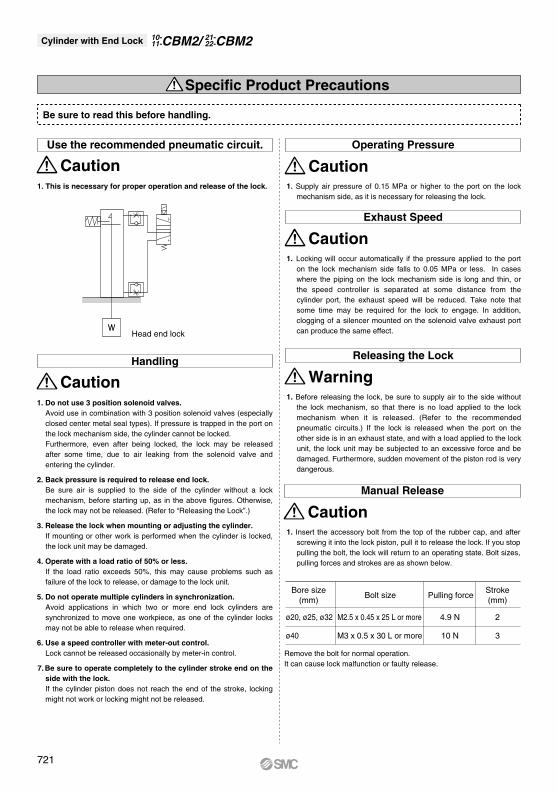
CautionUse the recommended pneumatic circuit. Operating Pressure
1. This is necessary for proper operation and release of the lock. 1. Supply air pressure of 0.15 MPa or higher to the port on the lock mechanism side, as it is necessary for releasing the lock.
CautionHandling
Caution
Exhaust Speed
Caution
Manual Release
1. Insert the accessory bolt from the top of the rubber cap, and after screwing it into the lock piston, pull it to release the lock. If you stop pulling the bolt, the lock will return to an operating state. Bolt sizes, pulling forces and strokes are as shown below.
Caution
Releasing the Lock
1. Before releasing the lock, be sure to supply air to the side without the lock mechanism, so that there is no load applied to the lock mechanism when it is released. (Refer to the recommended pneumatic circuits.) If the lock is released when the port on the other side is in an exhaust state, and with a load applied to the lock unit, the lock unit may be subjected to an excessive force and be damaged. Furthermore, sudden movement of the piston rod is very dangerous.
Warning
Head end lock
Bore size(mm)
Stroke(mm)
Bolt size
Remove the bolt for normal operation. It can cause lock malfunction or faulty release.
Pulling force
ø20, ø25, ø32 M2.5 x 0.45 x 25 L or more
M3 x 0.5 x 30 L or moreø40 10 N
4.9 N
3
2
1. Do not use 3 position solenoid valves. Avoid use in combination with 3 position solenoid valves (especially closed center metal seal types). If pressure is trapped in the port on the lock mechanism side, the cylinder cannot be locked. Furthermore, even after being locked, the lock may be released after some time, due to air leaking from the solenoid valve and entering the cylinder.
2. Back pressure is required to release end lock.Be sure air is supplied to the side of the cylinder without a lock mechanism, before starting up, as in the above figures. Otherwise, the lock may not be released. (Refer to “Releasing the Lock”.)
3. Release the lock when mounting or adjusting the cylinder.If mounting or other work is performed when the cylinder is locked, the lock unit may be damaged.
4. Operate with a load ratio of 50% or less. If the load ratio exceeds 50%, this may cause problems such as failure of the lock to release, or damage to the lock unit.
5. Do not operate multiple cylinders in synchronization.Avoid applications in which two or more end lock cylinders are synchronized to move one workpiece, as one of the cylinder locks may not be able to release when required.
6. Use a speed controller with meter-out control.Lock cannot be released occasionally by meter-in control.
7. Be sure to operate completely to the cylinder stroke end on the side with the lock.If the cylinder piston does not reach the end of the stroke, locking might not work or locking might not be released.
1. Locking will occur automatically if the pressure applied to the port on the lock mechanism side falls to 0.05 MPa or less. In cases where the piping on the lock mechanism side is long and thin, or the speed controller is separated at some distance from the cylinder port, the exhaust speed will be reduced. Take note that some time may be required for the lock to engage. In addition, clogging of a silencer mounted on the solenoid valve exhaust port can produce the same effect.
Specific Product Precautions
Be sure to read this before handling.
Cylinder with End Lock CBM221-22-CBM2/10-
11-
721