series 21/31 installation instructions and field …
TRANSCRIPT

SERIES 21/31 INSTALLATION INSTRUCTIONSand field service check list
BULLETIN MI2045-01/04REPLACED MI1081
SERIES 21 Amplifiers (single furnace):A1010A - use with TD121A1010B - high fire ignition - use with TD121A1010E - integral temp. selectorA1010F - integral temp. selector and high fire ignition
SERIES 31 Amplifiers (multiple furnace):A1011A - use with TD121A1011B - high fire ignition - use with TD121A1011E - integral temp. selectorA1011F - integral temp. selector and high fire ignition
Modulator-Regulator Valves:MR410 - (3/8" and 1/2" pipe size)MR510 - (1/2" and 3/4" pipe size)MR610 - (3/4" and 1" pipe size)
Remote Temperature Selectors:TD121 - (55o to 90o F)TD121A - (80o to 130o F)TD121B - (120o to 170o F)TD121C - (160o to 210o F)TD121D - (200o to 250o F)TD121E - (100o to 250o F)TD121F - (40o to 80o F)NOTE: Remote Selector and Discharge Temperature Sensormust have same temperature range to be compatible.Optional: ETD-1 enclosure, EFP-1 cover plate only - no enclosure
Discharge Temperature Sensors: use with Mixing TubeTS121 - (55o to 90o F)TS121A - (80o to 130o F)TS121B - (120o to 170o F)TS121C - (160o to 210o F)TS121D - (200o to 250o F)TS121E - (100o to 250o F)TS121F - (40o to 80o F)
Mixing Tubes: used with SensorsMT1-9 or 2-9 (9" length)MT1-12 or 2-12 (12" length)MT1-23 or 2-23 (23" length)MT1-28 or 2-28 (28" length)MT1-57 (57" length)
Optional:
Inlet Air Sensors: use with Mixing TubeTS10765A - (8:1 ratio)TS10765B - (5:1 ratio)TS10765C - (3.5:1 ratio)
Override Stat: use with TD121 onlyT115 - (40o to 90o F)
Override Stat
A1010 Amplifier A1011 Amplifier
System Components
Table of ContentsPage 2 Introduction and DimensionsPage 3 Specifications
Installation of ComponentsPage 4 & 5 Field Service ChecklistPage 6 Preliminary Circuit Analysis
Performance CheckExtended High-Fire Ignition
Page 7 Wiring DiagramsPage 8 Temperature Calibration
Valve Adjustments
ValveRemote Temperature Selector
Sensor and MixingTube

3.00�(76.2)
1.50�(38.1)
2.96
1.25
1-9/164-3/16
1.503.00 REF
MOUNTING HOLE�4-PLACES
2.56
6.00�(152.4)
2.00�(50.8)
Length (See page1)
MOUNTING HOLES
1.411.69
4.69
�
3.46�3.25
2.50�REF.�
4-3/16�
1.00 DIA.
#10-16 x 1/2 LG.�BINDING HD. SHEETMETAL SCR.2-REQ'D.
3.38�(85.9)�
1.69�(42.9)�
2.60�(66.0)
9.50�(241.3)
1.25�(31.8)
RUBBER GROMMET(BOTH ENDS)5/8"I.D.(15.9)
2.75�(69.9)
2.75�(69.9)
8.00�(203.2)
.75
(19.1)
1.75�(44.5)
2.56�(65.1)
MOUNTING HOLES�2 REQ'D.5.50�
(139.7)
4.19�(106.4)
4.19�(106.4)
1.88�(47.6)
#10-16 x 1/2 LG.BINDING HD. SHEETMETAL SCR.2-REQ'D.
T115
A1010
A1011
TD121
MIXING TUBES
Selectra SERIES 21/31 electronic gas flame modulation systems are designed primarily for make-up air heating, as components of indirect fired units with atmospheric burners. All fuel gases are compatible.
The SERIES 21 is designed for single function operation, and the SERIES 31 is capable of handling up to four furnances. They may be field installed on existing equipment or specified for new equipment installation.
The systems utilize Modulator-Regulator valves. Amplifiers are available for high-fire ignition with
integral or remote temperature selection. A discharge air temperature sensor is mounted within a mixing tube housing. Optionally, a room override thermostat provides space temperature control by raising the discharge air temperature to a pre-selected point - when used in conjuction with the remote temperature selector. Also optional, an inlet air sensor (and mixing tube) provides inverse change in discharge air for each degree change in inlet air - when installed in a convenient duct location upstream of the burner.
Introduction and Dimensions
2
SpecificationsGases: All fuel gases.
Pressure Limits:Inlet (maximum) MR410 / 510 / 610.....1 psi / 69 mbar
Outlet (maximum fire)standard spring*.....3.0" to 5.0" w.c. / 7 to 12 mbarH - models.....7.5" to 12" w.c. / 19 to 30 mbarMax. set point not to exceed 10" w.c. above min.set point
Outlet (minimum fire)MR*10B10L standard spring*.....0.2" to 1.2" w.c. /.5 to 3 mbarMR*10B10L-1 spring*.....1" to 2.8" w.c. / 2.5 to 7 mbar* other spring ranges available - consult factory
Power Requirements:Single Furnace.....24V AC, 40VA capacityMultiple Furnace.....24V AC, 100VA capacityNOTE: Transformer secondary must not be groundedin any portion of the circuit external to a Maxitrolamplifier. If existing transformer is grounded, aseparate isolated transformer must be used. Electricalinterference may effect performance and/or damageequipment.
Temperature Control Range:Standard.....55o to 90o FOptional ranges to.....250o F
Ambient Limits: -30o to 125o F / -34o to 52o C
Remote Selector: Install in control cabinet or other chosenlocation. Remove cover and wire as shown in diagram,page 7 - reassemble.
Room Override Thermostat: Place in heated area tosense average room temperature, not in direct path ofdischarge air stream. Use only with TD121 RemoteTemperature Selector. Wire as shown in diagram, page 7.
Note: For systems using up to four automatic gas valveswith 0.8 amp maximum current each, a 100VA transformerwill be adequate.
In the event that an automatic valve's current exceeds 0.8amps, it would be advisable to wire according to the'Independent Power Supply' diagram, page 7. Thetransformer for the modulating power - terminals 8 and 9 -should be 40VA, and the automatic valve transformershould be capable of handling required loads up to 3.5 ampsmaximum. If exceeding 3.5 amps, it will be necessary tooperate an auxiliary relay with contact rating sufficient tohandle the automatic valves.
Wiring Run: Control wires connected to the Override Stat,Discharge Air Sensor, or Remote Temperature Selectormust not be run close to or inside conduit with power orignition wires. Doing so may cause the unit to functionerratically or may destroy the amplifier. If shielded wiresare used, shield must be insulated and grounded at theamplifier location only.
Amplifier: Slide or snap out circuit board from amplifierbase. Mount base with two screws in chosen locationprotected from weather or contaminated atmosphere.Amplifier is ready for wiring when circuit board is replacedon base - protective cover need not be removed.
Discharge Temperature Sensor (in Mixing Tube): Cuthole in air duct - install several feet from heat exchanger toavoid thermal radiation effects. Locate in discharge airstream. Remove cover and wire as shown in diagram, page7 - reassemble.
Installation of Components
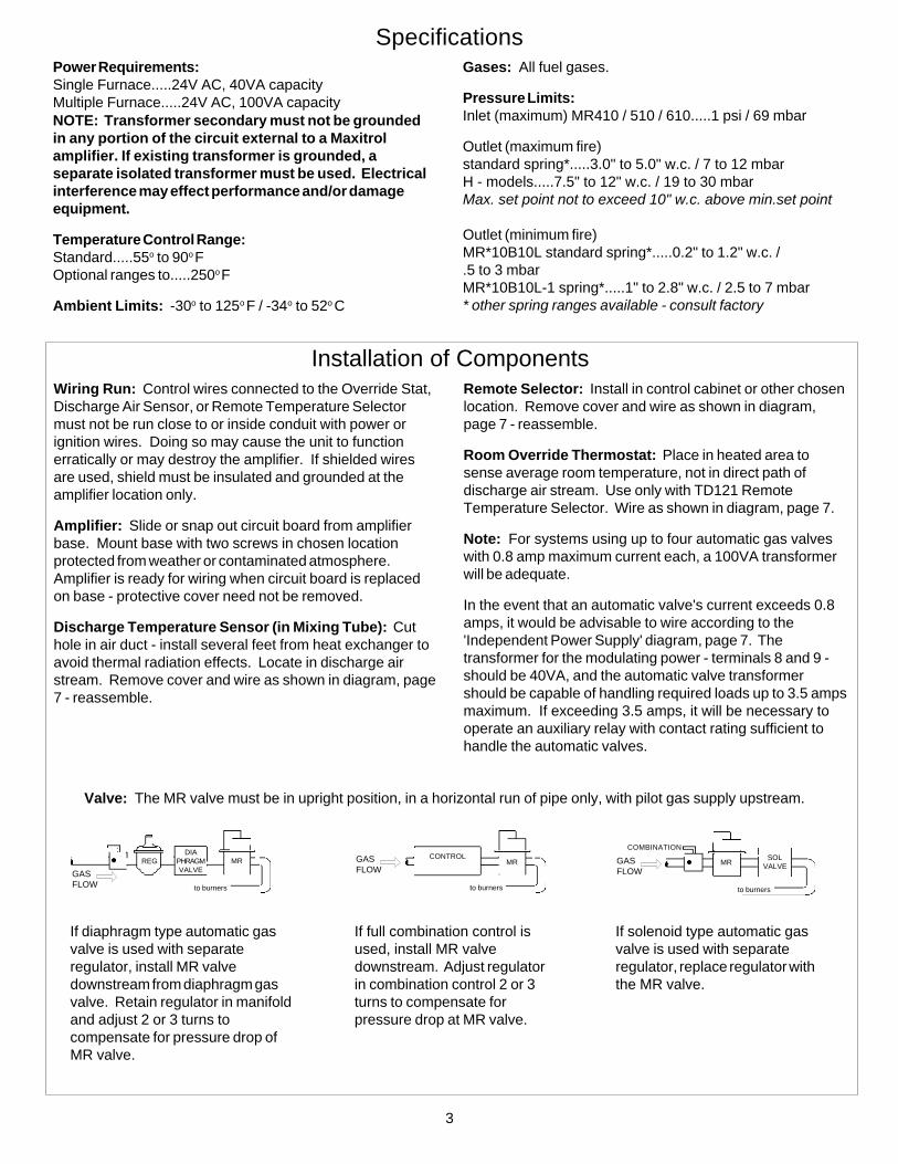
Valve: The MR valve must be in upright position, in a horizontal run of pipe only, with pilot gas supply upstream.
If diaphragm type automatic gasvalve is used with separateregulator, install MR valvedownstream from diaphragm gasvalve. Retain regulator in manifoldand adjust 2 or 3 turns tocompensate for pressure drop ofMR valve.
If full combination control isused, install MR valvedownstream. Adjust regulatorin combination control 2 or 3turns to compensate forpressure drop at MR valve.
If solenoid type automatic gasvalve is used with separateregulator, replace regulator withthe MR valve.
GASFLOW
REG MR
to burners
DIAPHRAGMVALVE
to burners
MRCONTROLGAS
FLOWMR
SOLVALVE
GASFLOW
to burners
COMBINATION
3

1.Fa
ulty
aut
omat
ic c
ontro
l val
ve.
2.In
stal
latio
n w
iring
err
or.
3.A
mpl
ifier
is fa
ulty
.
1.R
emov
e w
ire fr
om v
alve
, if v
alve
doe
s no
t clo
se v
alve
is fa
ulty
.
2.R
emov
e w
ire fr
om a
mpl
ifier
term
inal
10
or 1
1. If
val
ve re
mai
ns o
pen,
che
ck fo
r mis
wiri
ng.
3.If
AC
vol
tage
will
not
dro
p at
term
inal
s 8
and
11 -
whe
n D
C v
olta
ge a
t ter
min
als
1 an
d 2
isab
ove
20V
DC
- am
plifi
er is
faul
ty. I
f spa
ce te
mpe
ratu
re is
less
than
60°
or g
reat
er th
an85
°F (
< 16
° or >
29°
C),
see
Pre
limin
ary
Circ
uit A
naly
sis,
pag
e 6.
1.R
epla
ce a
utom
atic
con
trol v
alve
.
2.C
orre
ct w
iring
.
3.R
epla
ce a
mpl
ifier
.
4.R
ead
volta
ge a
cros
s va
lve
term
inal
s. If
24
V A
C, v
alve
is fa
ulty
.
5.R
ead
volta
ge a
cros
s te
rmin
als
8 an
d 11
on
ampl
ifier
. If 2
4 V
AC
, che
ck fo
r ope
nci
rcui
t to
auto
mat
ic v
alve
. If s
pace
tem
pera
ture
is le
ss th
an 6
0° o
r gre
ater
than
85°
F(<
16° o
r >29
°C),
see
Pre
limin
ary
circ
uit A
naly
sis,
pag
e 6.
6.
If A
C v
olta
ge re
adin
g re
mai
ns z
ero
- whe
n D
C v
olta
ge a
t ter
min
als
1 an
d 2
is b
elow
14 V
DC
-am
plifi
er is
faul
ty. I
f spa
ce te
mpe
ratu
re is
less
than
60°
or g
reat
er th
an85
°F (<
16° o
r >29
°C),
see
Pre
limin
ary
Circ
uit A
naly
sis,
pag
e 6.
4.R
epla
ce a
utom
atic
con
trol v
alve
.
5.C
orre
ct w
iring
.
6.R
epla
ce a
mpl
ifier
.
7.P
ower
sup
ply
mus
t be
24 V
AC
.
8.In
stal
l pro
perly
.
SY
MP
TOM
PO
SS
IBLE
CA
US
EFI
ELD
TE
ST
RE
ME
DY
Fiel
d S
ervi
ce C
heck
list
4.Fa
ulty
aut
omat
ic c
ontro
l val
ve.
5.O
pen
wire
to a
utom
atic
val
ve.
6.A
mpl
ifier
is fa
ulty
.
7.Fa
ulty
pow
er s
uppl
y.
8.M
R v
alve
inst
alle
d ba
ckw
ards
.
7.R
ead
volta
ge a
t am
plifi
er te
rmin
als
8 an
d 14
(24
V A
C).
8.A
rrow
on
MR
val
ve s
houl
d po
int i
n di
rect
ion
of g
as fl
ow.
9.R
oom
Ove
rrid
e Th
erm
osta
t, if
used
, cal
lsfo
r hea
t.
10.O
pen
circ
uit i
n se
nsin
g an
d se
tting
circ
uit.
9.R
emov
e T1
15 w
ires
from
am
plifi
er te
rmin
als
3 an
d 14
.
10.D
isco
nnec
t and
mea
sure
acr
oss
wire
s co
nnec
ted
to a
mpl
ifier
term
inal
s 3
and
4 (A
1010
mod
els)
. Sho
uld
read
bet
wee
n 8,
000
and
12,0
00 o
hms.
9.If
prop
er o
pera
tion
is o
btai
ned,
che
ck th
e th
erm
osta
t wiri
ng fo
r sho
rts.
Rot
ate
ther
mos
tat d
ial a
bove
and
bel
ow ro
om te
mpe
ratu
re to
pro
veth
erm
osta
t fun
ctio
n.
10.I
f abo
ve 1
2,00
0 oh
ms,
che
ck c
ircui
t for
ope
n or
loos
e w
ires.
11.C
heck
wiri
ng fo
r def
ects
.
12.P
lung
er s
houl
d be
sm
ooth
, cle
an, a
nd o
pera
te fr
eely
in s
olen
oid
slee
ve.
13.M
easu
re v
olta
ge a
cros
s M
R v
alve
.
11.
Ope
n ci
rcui
t in
wiri
ng to
MR
val
ve.
12.
Plu
nger
jam
med
or i
nsta
lled
upsi
de d
own.
13.
Faul
ty M
R v
alve
.
11.R
epla
ce w
iring
if n
eces
sary
.
12.C
lean
or r
epla
ce p
lung
er.
13.I
f mod
ulat
ing
volta
ges
are
obta
ined
but
no
gas
mod
ulat
ion,
MR
val
veis
faul
ty. R
epla
ce if
nec
essa
ry.
14.D
isco
nnec
t and
mea
sure
acr
oss
wire
s co
nnec
ted
to a
mpl
ifier
term
inal
s 3
and
4 (A
1010
mod
els)
. Sho
uld
read
bet
wee
n 8,
000
and
12,0
00 o
hms.
14. S
hort
circ
uit i
n se
nsin
g an
d se
ttlin
g ci
rcui
t.14
.If b
elow
8,0
00 o
hms,
che
ck c
ircui
t for
sho
rts o
rm
isw
iring
.
15.H
eat l
oad
requ
ires
low
fire
onl
y.
16.P
lung
er a
nd/o
r max
imum
spr
ing
mis
sing
.
17.J
amm
ed p
lung
er
18.O
ther
val
ve fa
ults
.
19.I
nade
quat
e su
pply
pre
ssur
e.
15.I
ncre
ase
tem
pera
ture
setti
ng 1
0 de
gree
s.
16.C
heck
for p
arts
(see
'Val
ve A
djus
tmen
ts' fi
gure
, pag
e 8)
.
17.E
xam
ine.
Plu
nger
sho
uld
be c
lean
, sm
ooth
, and
ope
rate
free
ly in
sol
enoi
d sl
eeve
.
18.R
emov
e w
ire fr
om M
R v
alve
.
19.R
emov
e sp
ring
5 fro
m M
R v
alve
(see
val
ve fi
gure
, pag
e 8)
, pus
h do
wn
on p
lung
er.
Insu
ffici
ent m
anifo
ld p
ress
ure
with
furn
ace
oper
atin
g in
dica
tes
supp
ly is
too
low
.
15.I
f hea
ter g
oes
to h
igh
fire,
sys
tem
is w
orki
ng c
orre
ctly
.
16.I
nsta
ll cor
rect
par
ts.
17.C
lean
, or r
epla
ce p
lung
er if
nec
essa
ry.
18.I
f MR
val
ve re
mai
ns o
n lo
w fi
re, v
alve
may
be
faul
ty.
Che
ck it
em 1
9 be
low
, the
n re
plac
e va
lve
if ne
cess
ary.
19.C
heck
for o
bstru
ctio
n in
gas
pip
e ah
ead
of c
ontro
ls.
Incr
ease
gas
pre
ssur
e if
poss
ible
.
20.R
ecal
ibra
te p
er 'T
empe
ratu
re C
alib
ratio
n' p
roce
dure
.20
.Cal
ibra
tion.
20.C
heck
sea
l on
calib
ratio
n po
tent
iom
eter
.
21. D
irty
or s
ticki
ng p
lung
er.
22. I
nter
mitt
ent s
horti
ng in
wiri
ng.
23. F
aulty
am
plifi
er.
21.C
lean
, or r
epla
ce p
lung
er if
nec
essa
ry.
22.C
orre
ct w
iring
.
23.I
f err
atic
or p
ulsa
ting
DC
vol
tage
is o
bser
ved
and
wiri
ngsh
ows
no d
efec
ts, r
epla
ce a
mpl
ifier
. If e
rrat
ic o
rpu
lsat
ing
volta
ge co
ntin
ues,
cont
act M
axitr
ol.
21.E
xam
ine.
Plu
nger
sho
uld
be c
lean
, sm
ooth
, and
ope
rate
free
ly in
sol
enoi
d sl
eeve
.
22.I
nspe
ct w
iring
.
23.O
bser
ve D
C v
olta
ge a
cros
s am
plifi
er te
rmin
als
1 an
d 2.
*Con
trol
cir
cuits
ext
erna
l to
the
Ser
ies
21 a
nd 3
1 ca
n ca
use
burn
er m
alfu
nctio
n. A
lway
s ch
eck
man
ual v
alve
to b
e ce
rtai
n ga
s is
on,
and
che
ck li
mit
cont
rols
for n
orm
al o
pera
tion.
A.
B. C.
D.
Aut
omat
ic c
ontr
ol v
alve
will
not
clo
sede
spite
full
rang
e of
mod
ulat
ing
volta
geat
term
inal
s 1
and
2.
Aut
omat
ic c
ontr
ol v
alve
won
’t op
ende
spite
full
rang
e of
mod
ulat
ing
volta
ge a
t ter
min
als
1 an
d 2.
No
gas
flow
.
Con
tinuo
us h
igh
fire.
E. F.
Con
tinuo
us h
igh
fire
but a
utom
atic
valv
e cy
cles
.
Furn
ace
won
’t ac
tivat
e du
e to
con
stan
thi
gh m
odul
atin
vol
tage
(abo
ve 1
7 V
DC
).
G.
H.
Con
tinuo
us lo
w o
r med
ium
fire
, but
auto
mat
ic v
alve
cyc
les
corr
ectly
.
Inco
rrec
t dis
char
ge a
ir te
mpe
ratu
re.
I.Er
ratic
or s
ever
ly p
ulsa
ting
flam
e.

Automatic Valve Function:After the electronic modulation function is tested, a voltagereading must be taken across the automatic gas valve.These voltage readings will be approximately 24 V AC withthe temperature selection knob at maximum setting, zerovolts AC with the selector at minimum setting. The relayswitching action should occur when the modulating voltageis between 15 and 19V DC.
If these voltage readings are observed as noted, it is provedthat the amplifier and temperature selector are operatingproperly.
After testing, remove the resistor and reconnect thedischarge air sensor.
Preliminary Circuit AnalysisIn order to diagnose the cause of problems in this system itis necessary to determine certain values. It is helpful tohave an AC and DC voltmeter and an ohmmeter capable ofreading 0 to 15,000 ohms. For ease in trouble shooting, itis necessary to rewire the system, replacing the dischargeair sensor with a 4500 ohm (4300 ohm + 200 ohm), 1/2 watttest resistor.
Modulating Function Test:Connect a DC voltmeter to amplifier terminals 1 and 2. Ifmore convenient, the meter may be attached to the MRvalve terminals. Rotate temperature selection knob tomaximum setting - the DC volts should read zero. Thevoltage should gradually increase to at least 20 volts whenthe temperature selector is slowly rotated to its minimum(generally over a 3° to 4° range).
With the modulator-regulator valve installed as instructed(voltages are approximate)...
Minimum fire is above 14 volts DC.Manifold pressure can be adjusted as folows:MR*10B10L Standard spring 0.2" to 1.2" w.c.(.5 to 3 mbar)MR*10B10L-1 spring 1" to 2.8" w.c.(2.5 to 7 mbar)Maximum fire is obtained at zero volts DC.Use manufacturer's pressure specifications when available.Maxitrol standard factory settings are 0.5" w.c. (1.25 mbar)minimum and 3.5" w.c. (8.75 mbar) maximum. H-1 models1.75" w.c. (4.35 mbar) minimum and 11" w.c. ( 27 mbar)maximum.
At Temperature Selector:1) Set the selector at least 10o higher than incoming air andallow discharge air temperature to stabilize. Discharge airtemperature should agree with temperature selector setting.2) Increase temperature setting by 5o to 10o. Heatermanifold pressure should immediately go to high fire.
Manifold pressure will decrease as the discharge airtemperature approaches the setting and will stabilize at thetemperature setting.3) Decrease temperature to the original setting. Burnershould immediately turn off. Then, as the discharge airtemperature decreases, the burner should ignite at low fire.The discharge air temperature should again stabilize at thetemperature setting. On amplifiers containing a high fireignition function, refer to Extended High-Fire Ignition sectionbelow.
If the preceding readings are not obtained:4) Recheck wiring to ensure system is consistent withappropriate wiring diagram.5) Check power source for 24 volts.6) Some automatic control valves require as much as 20seconds to open. In this case, check for 24VAC output atautomatic valve terminals.
Note: Depending on the Btu capacity of the heater and thetemperature rise, the discharge air temperature may becontrolled by a continuous modulated flame (hightemperature rises) or by on/off operation (low temperaturerises).
Performance Check
Extended High-Fire Ignition
On A1010B, A1010F, A1011B, and A1011F amplifiers, thehigh fire start duration is approximately five seconds. Toextend it from 5 seconds to approximately 25 seconds,remove 100K (brown-black-yellow-gold) resistor from boardas shown.
On furnaces equipped with slow opening automatic valves,it is recommended to make this modification.
Snip Off Resistor
5

Single Furnace Operation - Series 21
Preliminary Circuit Analysis
Multiple Furnace Operation - Series 31(MR valves and automatic gas valves wired in parallel as shown)
A1010AA1010B
(Series 21)
A1010EA1010F
(Series 21)
6

Temperature Calibration
Note: High Fire Adjustment should be checked whenever Low Fire Adjustment is changed.
Disconnect wire from amplifier terminal 3, remove cover plate (2).
(See bulletin MT2035 for additional M/MR valve information)
Valve Adjustments
1. TOP HOUSING2. COVER PLATE3. SEAL GASKET4. MAXIMUM ADJUSTMENT SCREW5. MAXIMUM ADJUSTMENT SPRING6. SOLENOID7. MINIMUM ADJUSTMENT SPRING8. PLUNGER9. MINIMUM ADJUSTMENT SCREW10. MINIMUM ADJUSTMENT SCREW STOP
21
9
6
5
3
4
8
7
10
If needed - amplifier potentiometer adjustment - for heatsensing with Discharge Temperature Sensor (TS121) :Install a thermometer or other temperature measuringdevice at a point adjacent to the tip of the TS121 DischargeAir Sensor. Set the temperature selector at least 15o abovethe existing outdoor air temperature. (Accurate calibrationcannot be made at temperature differentials of less than15o.)
Adjust calibrating potentiometer (A) until thermometerreading agrees with temperature setting. Note: Adjust (A)in small increments and allow time for the discharge airtemperature to stabilize after each adjustment.
High Fire Adjustments:A) Using maximum adjustment screw (4), set manifoldpressure to furnace manufacturer's specifications.B) Replace cover plate (2) on Modulator-Regulator valveand reconnect wire to amplifier terminal 3.
Low Fire Adjustments:A) Remove maximum adjusting screw (4), spring (5), andplunger (8). A small magnet is useful for this purpose.CAUTION - The plunger is a precision part. Handlecarefully to avoid marring or picking up grease and dirt. Donot lubricate.B) Using minimum adjusting screw (9), set manifoldpressure to furnace manufacturer's specifications.C) Replace plunger and spring retainer, spring, andmaximum adjusting screw in proper order.
8
CAUTION: Operation of combustion equip-ment can be hazardous resulting in bodilyinjury or equipment damage. Each burnershould be supervised by a combustion safe-guard and only qualified personnel shouldinstall, make system adjustments and per-form any required service.
NOTICE: Maxitrol practices a policyof continuous improvement in the de-sign of its products. It reserves theright to change the specifcations atany time without prior notice.
ORDAN THERMAL PRODUCTS LTDCombustion Equipment & Controls for Industry
21 Amber St # 9, Markham Ontario Canada L3R 4Z3 Tel: (905) 475-9292 Fax: (905) 475-3286
www.ordanthermal.com