series 3730 type 3730-5 electropneumatic positioner with ... · type 3730-5 electropneumatic...
TRANSCRIPT

Data Sheet T 8384-5 EN
Associated Information Sheet u T 8350 Edition December 2017
Fig. 1: Type 3730 Direct attachment to Type 3277 Pneumatic Actuator
Fig. 2: Type 3730 Attachment according to NAMUR
Fig. 3: Type 3730 Attachment according to VDI/VDE 3845
Fig. 4: Type 3730 External position sensor with Type 3510 Micro-flow Valve
The microprocessor-controlled positioner compares the refer-ence variable cyclically transmitted over the FOUNDATION™ field-bus network to the travel or opening angle of the control valve and issues a corresponding output signal pressure.The Type 3730-5 Positioner communicates according to FOUNDATION™ fieldbus specification with field devices, program-mable logic controllers and process control systems.An integrated PID function block allows the control of process variables required directly in the field. The shift to distributed control reduces the number of control tasks to be performed by the higher-level automation system. The Link Master Capa-bility allows autonomous closed control loops to be set up in the field.
Special features • Integrated function blocks: 1 PID Control (PID), 1 Analog
Output (AO), 1 Multiple Analog Output (MAO), 1 Multi-ple Analog Input (MAI), 2 Discrete Outputs (DO), 2 Dis-crete Inputs (DI)
• Link Master Capability • DO function blocks to start/execute diverse functions (e.g.
start the data logger) • Two DI function blocks to analyze binary input signals • Simple attachment to all common linear and rotary actua-
tors – SAMSON direct attachment (Fig. 1) – NAMUR rib (Fig. 2) – Attachment to rod-type yokes acc. to IEC 60534-6-1 – Attachment according to VDI/VDE 3847 – Rotary actuator attachment according to VDI/
VDE 3845 (Fig. 3) • Any desired mounting position of the positioner (but not
suspended) • Single-knob, menu-driven operation • Automatic start-up • LCD easy to read in any mounted position due to select-
able reading direction • Integrated EXPERTplus diagnostics for control valves
(u T 8389)
• Classified status alarms acc. to NAMUR Recommendation NE 107
• Online changing of control parameters • Automatic zero monitoring • Calibrated travel sensor without gears susceptible to wear
Series 3730Type 3730-5 Electropneumatic Positioner with FOUNDATION™fieldbuscommunication
ApplicationPositioners for attachment to pneumatic control valvesValvetravelfrom3.6to300 mm·Openingangle24to100°Smart, bus-powered field device complying with FOUNDATION™
fieldbus specifications based on IEC 61158-2 transmission technology.

2 T 8384-5 EN
• Permanent storage of parameters (protected against power failure)
• Adjustable output pressure limitation • Activatable tight-closing function • Binary input for DC voltage signals
Additional options – Inductive limit contact with proximity switches – Integrated solenoid valve – Binary input for floating contact – Leakage sensor – External position sensor (Fig. 4) – Stainless steel housing
Principle of operationThe positioner is mounted on pneumatic control valves and is used to assign the valve position (controlled variable x) to the control signal (set point w). The positioner compares the elec-tric control signal of a control system to the travel or rotational angle of the control valve and issues a signal pressure (output variable y) for the pneumatic actuator.The positioner mainly consists of an electric travel sensor sys-tem, an analog i/p module with a downstream air capacity booster and the electronics with the microcontroller. When a set point deviation occurs, the actuator is either vented or filled with air. If necessary, the signal pressure change can be slowed down with a volume restriction that can be connected as necessary. The signal pressure supplied to the actuator can be limited by software or on site to 1.4, 2.4 or 3.7 bar. The
fixed flow regulator ensures a constant air flow to the atmo-sphere, which is used to flush the inside of the positioner housing and to optimize the air capacity booster. The i/p module is supplied with a constant upstream pressure by the pressure regulator to compensate for any fluctuations in the supply pressure.The positioner communicates and is powered using IEC 61158-2 transmission technology conforming to FOUNDATION™ fieldbus specification.As a standard feature, the positioner comes with a binary in-put used to signalize process information over the FOUNDATION™ fieldbus network.
OperationA single rotary pushbutton facilitates operation. The parame-ters are selected by turning the rotary pushbutton, pushing it activates the required setting. All parameters can be checked and changed on site. All values are displayed on the LCD. The reading direction of the LCD can be rotated by 180°. The closing direction of the control valve is indicated to the posi-tioner by setting the DIP switch "Air to open/Air to close". It assigns the CLOSED position of the control valve to the 0 % reading. The INIT key activates initialization which is started according to the ready adjusted parameters. After initializa-tion is completed, the positioner immediately starts closed-loop operation.
w
x
Q
%S
mm
GG
PD
SerialInterface
16
15 BE2
BE1
112
4
13
20
17 18
19
24V DC
5
3
12
6
7
8
10
1
14
9
xy
FOUNDATION™ fieldbus IEC 61158-2
1 Control valve 2 Travel sensor 3 PD controller 4 A/D converter 5 Microcontroller 6 i/p converter 7 Air capacity booster 8 Pressure regulator9 Flow regulator10 Volume restriction11* Inductive limit contact12* Solenoid valve13 IEC 61158-2 interface module14 Binary input 1 (voltage input)15* Binary input 2
(for floating contact)16 Display17* Actuation of solenoid valve18 Galvanic isolation for
detection of the actuation of the solenoid valve
19 D/A converter20 Serial interface (SSP)* Optional
Fig. 5: Functional diagram of Type 3730-5 Positioner
T 8384-5 EN 3
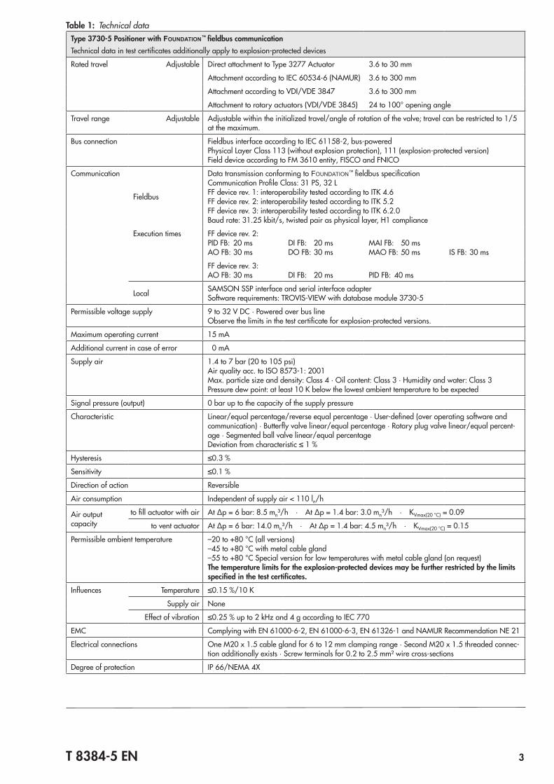
Table1: Technical dataType 3730-5 Positioner with FOUNDATION™ fieldbuscommunicationTechnical data in test certificates additionally apply to explosion-protected devices
Rated travel Adjustable Direct attachment to Type 3277 Actuator 3.6 to 30 mm
Attachment according to IEC 60534-6 (NAMUR) 3.6 to 300 mm
Attachment according to VDI/VDE 3847 3.6 to 300 mm
Attachment to rotary actuators (VDI/VDE 3845) 24 to 100° opening angle
Travel range Adjustable Adjustable within the initialized travel/angle of rotation of the valve; travel can be restricted to 1/5 at the maximum.
Bus connection Fieldbus interface according to IEC 61158-2, bus-poweredPhysical Layer Class 113 (without explosion protection), 111 (explosion-protected version)Field device according to FM 3610 entity, FISCO and FNICO
Communication
Fieldbus
Data transmission conforming to FOUNDATION™ fieldbus specificationCommunication Profile Class: 31 PS, 32 LFF device rev. 1: interoperability tested according to ITK 4.6FF device rev. 2: interoperability tested according to ITK 5.2FF device rev. 3: interoperability tested according to ITK 6.2.0Baud rate: 31.25 kbit/s, twisted pair as physical layer, H1 compliance
Execution times FF device rev. 2:PID FB: 20 msAO FB: 30 ms
DI FB: 20 msDO FB: 30 ms
MAI FB: 50 msMAO FB: 50 ms IS FB: 30 ms
FF device rev. 3:AO FB: 30 ms DI FB: 20 ms PID FB: 40 ms
Local SAMSON SSP interface and serial interface adapterSoftware requirements: TROVIS-VIEW with database module 3730-5
Permissible voltage supply 9 to 32 V DC · Powered over bus lineObserve the limits in the test certificate for explosion-protected versions.
Maximum operating current 15 mA
Additional current in case of error 0 mA
Supply air 1.4 to 7 bar (20 to 105 psi)Air quality acc. to ISO 8573-1: 2001Max. particle size and density: Class 4 · Oil content: Class 3 · Humidity and water: Class 3Pressure dew point: at least 10 K below the lowest ambient temperature to be expected
Signal pressure (output) 0 bar up to the capacity of the supply pressure
Characteristic Linear/equal percentage/reverse equal percentage · User-defined (over operating software and communication) · Butterfly valve linear/equal percentage · Rotary plug valve linear/equal percent-age · Segmented ball valve linear/equal percentageDeviation from characteristic ≤ 1 %
Hysteresis ≤0.3 %
Sensitivity ≤0.1 %
Direction of action Reversible
Air consumption Independent of supply air < 110 ln/h
Air output capacity
to fill actuator with air At Δp = 6 bar: 8.5 mn³/h · At Δp = 1.4 bar: 3.0 mn³/h · KVmax(20 °C) = 0.09
to vent actuator At Δp = 6 bar: 14.0 mn³/h · At Δp = 1.4 bar: 4.5 mn³/h · KVmax(20 °C) = 0.15
Permissible ambient temperature –20 to +80 °C (all versions)–45 to +80 °C with metal cable gland–55 to +80 °C Special version for low temperatures with metal cable gland (on request)The temperature limits for the explosion-protected devices may be further restricted by the limits specifiedinthetestcertificates.
Influences Temperature ≤0.15 %/10 K
Supply air None
Effect of vibration ≤0.25 % up to 2 kHz and 4 g according to IEC 770
EMC Complying with EN 61000-6-2, EN 61000-6-3, EN 61326-1 and NAMUR Recommendation NE 21
Electrical connections One M20 x 1.5 cable gland for 6 to 12 mm clamping range · Second M20 x 1.5 threaded connec-tion additionally exists · Screw terminals for 0.2 to 2.5 mm² wire cross-sections
Degree of protection IP 66/NEMA 4X
4 T 8384-5 EN
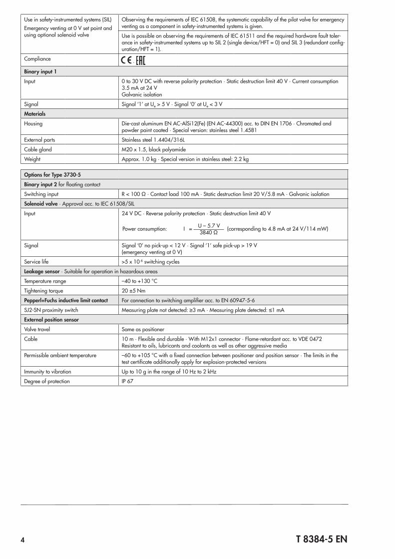
Use in safety-instrumented systems (SIL)Emergency venting at 0 V set point and using optional solenoid valve
Observing the requirements of IEC 61508, the systematic capability of the pilot valve for emergency venting as a component in safety-instrumented systems is given.
Use is possible on observing the requirements of IEC 61511 and the required hardware fault toler-ance in safety-instrumented systems up to SIL 2 (single device/HFT = 0) and SIL 3 (redundant config-uration/HFT = 1).
Compliance ·
Binary input 1
Input 0 to 30 V DC with reverse polarity protection · Static destruction limit 40 V · Current consumption 3.5 mA at 24 VGalvanic isolation
Signal Signal ‘1’ at Ue > 5 V · Signal ‘0’ at Ue < 3 V
Materials
Housing Die-cast aluminum EN AC-AlSi12(Fe) (EN AC-44300) acc. to DIN EN 1706 · Chromated and powder paint coated · Special version: stainless steel 1.4581
External parts Stainless steel 1.4404/316L
Cable gland M20 x 1.5, black polyamide
Weight Approx. 1.0 kg · Special version in stainless steel: 2.2 kg
OptionsforType3730-5
Binary input 2 for floating contact
Switching input R < 100 Ω · Contact load 100 mA · Static destruction limit 20 V/5.8 mA · Galvanic isolation
Solenoid valve · Approval acc. to IEC 61508/SIL
Input 24 V DC · Reverse polarity protection · Static destruction limit 40 V
Power consumption: I = U – 5.7 V (corresponding to 4.8 mA at 24 V/114 mW)3840 Ω
Signal Signal ‘0’ no pick-up < 12 V · Signal ‘1’ safe pick-up > 19 V(emergency venting at 0 V)
Service life >5 x 10 6 switching cycles
Leakage sensor · Suitable for operation in hazardous areas
Temperature range –40 to +130 °C
Tightening torque 20 ±5 Nm
Pepperl+Fuchs inductive limit contact For connection to switching amplifier acc. to EN 60947-5-6
SJ2-SN proximity switch Measuring plate not detected: ≥3 mA · Measuring plate detected: ≤1 mA
External position sensor
Valve travel Same as positioner
Cable 10 m · Flexible and durable · With M12x1 connector · Flame-retardant acc. to VDE 0472Resistant to oils, lubricants and coolants as well as other aggressive media
Permissible ambient temperature –60 to +105 °C with a fixed connection between positioner and position sensor · The limits in the test certificate additionally apply for explosion-protected versions
Immunity to vibration Up to 10 g in the range of 10 Hz to 2 kHz
Degree of protection IP 67

T 8384-5 EN 5
Table2: Explosion protection certificates
Type Certification Type of protection/comments
3730
-5
CCoENumber A P HQ MH 104 1343
Ex ia IIC T6Date 2013-04-19
Valid until 2018-04-18
STCC On request-5
1
1)
Number PTB 04 ATEX 2109 II 2G Ex ia IIC T6 Gb; II 2D Ex ia III T80°C DbDate 2017-05-11
Number RU-C-DE. 08.B.006971Ex ia IIC T6; Ex tb IIIC T80°C Db X, IP66Date 2014-12-15
Valid until 2019-12-14
IECExNumber IECEx PTB 06.0054 Ex ia IIC T6-T4 Gb;
Ex ia IIC T80 °C DbDate 2017-07-17
KCSNumber 11-KB4BO-0225
Ex ia IIC T6/T5/T4Date 2011-11-10
Valid until 2018-11-10
NEPSINumber GYJ111267
Ex ia IIC T6Date 2016-01-24
Valid until 2023-01-23
-53
CSANumber 1675804
Ex ia IIC T6; Class I, II, Div.1, Groups A, B, C, D, E, F, G;Ex nA II T6; Ex nL IIC T6; Class I, II, Div.2, Groups A, B, C, D, E, F, G;Class II, Div.1, Groups E, F, D; Class IIIType 4 Enclosure
Date 2017-05-23
FMNumber 3023605
Class I, Zone 0 AEx ia IIC; Class I, II, III, Div.1, Groups A-G; Class I, Div.2, Groups A-D; Class II, Div.2, Groups F, G
Date 2006-03-15
-55 1)
Number PTB 04 ATEX 2109II 2D Ex tb IIIC T80°C Db
Date 2017-05-11
IECExNumber IECEx PTB 06.0054
Ex tb IIIC T80 °C DbDate 2017-07-17
-58
2)
Number PTB 05 ATEX 2010 X II 3G Ex nA IIC T6 Gc; II 3D Ex tc IIIC T80°C DcDate 2017-06-22
Number RU-C-DE. 08.B.006972Ex nA ic IIC T6/T5/T4 Gc X; Ex tc IIIC T80°C Db X, IP66Date 2014-12-15
Valid until 2019-12-14
IECExNumber IECEx PTB 06.0054 Ex nA IIC T6-T4 Gc
Ex tc IIIC T80°C DcDate 2017-07-17
NEPSINumber GYJ111268
Ex nA II T6; Ex nL IIC T6Date 2016-01-24
Valid until 2021-01-23
1) EC type examination certificate2) Statement of conformity

6 T 8384-5 EN
ConfigurationusingTROVIS-VIEWThe SAMSON configuration software, TROVIS-VIEW, can be used to configure the positioner. For this purpose, the position-er is equipped with an additional digital interface to be con-nected to the RS-232 interface of a PC. TROVIS-VIEW adapts the positioner to any process requirements and allows the process to be checked while the process is running. The con-trol valve is linked to the process over the FOUNDATION™ fieldbus network. The PID function block integrated in the positioner can also be configured using TROVIS-VIEW. The configuration of the network connections for the PID function block is made by the NI-FBUS™ configurator or a corresponding digital pro-cess control system.NetworkandpositionerconfigurationwithNI-FBUS™config-uratorThe positioner can also be configured over the NI-FBUS™ con-figurator from National Instruments.The NI-FBUS™ configurator can be used to perform the plan-ning of the entire FOUNDATION™ fieldbus network. It also allows the use of PID controller in the positioner to implement a standalone loop in the field.
Electrical and bus connectionThe Type 3730-5 Positioner with FOUNDATION™ fieldbus commu-nication must be connected to bus segments conforming to IEC 61158-2. A shielded two-wire line is used for both supply power and data communication.
Mounting the positionerThe Type 3730 Electropneumatic Positioner can be attached directly to the Type 3277 Actuator (175 to 750 cm²) over a connection block. In actuators with “actuator stem extends” fail-safe action, the signal pressure is routed over an internal hole in the actuator yoke to the actuator. In actuators with “ac-tuator stem retracts” fail-safe action, the signal pressure is routed to the actuator over ready-made external piping.Using the appropriate bracket, the positioner can also be at-tached according to IEC 60534-6-1 (NAMUR recommenda-tion). The positioner can be mounted on either side of the con-trol valve.A pair of universal brackets is used for the attachment to Type 3278 Rotary Actuators or other rotary actuators accord-ing to VDI/VDE 3845. The rotary motion of the actuator is transferred to the positioner over a coupling wheel with travel indication.A special version of the positioner allows it to be attached ac-cording to VDI/VDE 3847. This type of attachment allows the positioner to be replaced quickly while the process is running by blocking the air in the actuator. The positioner can be at-tached directly to the Type 3277 Actuator using an adapter bracket or adapter block. Alternatively, it can be attached to the NAMUR rib of a control valve using an additional NAMUR connection block.A reversing amplifier is necessary for double-acting, spring-less actuators for the second opposing signal pressure.
Dimensions in mm
Direct attachment
40
34
210
86
164
2858
M 20x1.5
Output (38) Supply (9)
1480

T 8384-5 EN 7
NAMURattachment
Lever70 1558
46
34
Pressure gauge bracketG ¼ or ¼ NPT
or connecting plate
Attachment according toVDI/VDE 3847 Lever
62
164
38
200
164
164
13
62 24
Attachment to SAMSON Type 3277
Attachment to NAMUR rib
External position sensor 70
7028
Schil
d

8 T 8384-5 EN
Attachment to rotary actuators VDI/VDE 3845 (Sept. 2010) Fixing level 1 Size AA1 to AA4
Light version
Mounting unit CrNiMo steel bracket
8090
164
52 Output Y1
Output Y2
Supply (9)Output Y1
Output Y2
50
495979
80
130
58
150
Connecting plateG ¼ or ¼ NPT
Type 3710 Reversing Amplifier (optional)
Heavy-duty version 5686
13080
166
3086
Ø 101
80
52 Output Y1
Output Y2
Supply (9)Output Y1
Output Y2 Type 3710 Reversing Amplifier (optional)
Connecting plateG ¼ or ¼ NPT
Lever
Lever x y zS 17 mm 25 mm 33 mmM 25 mm 50 mm 66 mmL 70 mm 100 mm 116 mmXL 100 mm 200 mm 216 mm
x
zy 16
10...17

T 8384-5 EN 9
OrderingtextType 3730-5... Positioner with FOUNDATION™ fieldbus communi-cation – Without pneumatic connecting rail
(only when directly attached to Type 3277) – With pneumatic connecting rail ISO 228/1-G ¼ – With pneumatic connecting rail ¼-18 NPT – Without/with pressure gauge up to max. 6 bar – Attachment to Type 3277 Actuator (175 to 750 cm²) – Attachment according to IEC 60534-6-1 (NAMUR)
Valve travel: ... mm, if applicable, rod diameter: … mm – Attachment according to VDI/VDE 3847
Valve travel: ... mm, if applicable, rod diameter: … mm – Attachment to Type 3278 Rotary Actuator (160/320 cm²),
mounting unit with CrNiMo steel bracket or heavy-duty attachment
– Attachment to rotary actuators acc. to VDI/VDE 3845, mounting unit with CrNiMo steel bracket or heavy-duty attachment
– Pneumatic reversing amplifier for double-acting actuators with connection acc. to ISO 228/1-G ¼ or ¼-18 NPT
– Adapter M20x1.5 to ½ NPT – Metal cable gland – Special version: housing made of CrNiMo steel

10 T 8384-5 EN
Article codePositioner Type 3730-5 x x x 0 x x x x 0 x 0 0 x 0 x xWith LCD and autotune, FOUNDATION™ fieldbusExplosion protectionWithout 0ATEX II 2G Ex ia IIC T6 Gb; II 2D Ex ia III T80°C Db 1CSA Ex ia IIC T6; Class I,II, Div.1, Groups A–G; Ex nA II T6; Ex nL IIC T6;
Class I, II, Div.2, Groups A–G; Class II, Div.1, Groups E–G; Class III3
FM Class I, Zone 0 AEx ia IIC; Class I, II, III, Div.1, Groups A, B, C, D, E, F, G; Class I, Div.2, Groups A, B, C, D; Class II, Div.2, Groups F, G
ATEX II 2D Ex tb IIIC T80°C DbATEX II 3G Ex nA IIC T6 Gc, II 3D Ex tc IIIC T80°C Dc 8Additional equipmentInductive limit contact Without 0
SJ2-SN (NC contact) 1Solenoid valve Without 0
With, 24 V DC 4External position sensor Without 0
With 0 1 0 0Leakage sensor Without 0
With 1Binary input Without 0
Floating contact 0 1DiagnosticsEXPERTplus 4Housing materialAluminum (standard) 0Stainless steel 1.4581 0 1Special applicationWithout 0Version compatible with paint 1Exhaust air port with ¼-18 NPT thread, back of positioner sealed 0 0 0 0 2Attachment according to VDI/VDE 3847 including interface 6Attachment according to VDI/VDE 3847 prepared for interface 7Special versionWithout 0 0 0NEPSI Ex ia IIC T6 1 0 0 9NEPSI Ex nA II T6; Ex nL IIC T6 8 0 1 0IECEx Ex ia IIC T6...T4 Gb; Ex ia IIC T80°C Db 1 0 1 2IECEx Ex tb IIIC T80°C Db 5 0 3 4IECEx Ex nA IIC T6...T4 Gc; Ex tc IIIC T80°C Dc 8 0 1 5EAC Ex 1Ex ia IIC T6; Ex tb IIIC T80°C Db X, IP66 1 0 1 4EAC Ex 2Ex nA ic IIC T6/T5/T4 Gc X; Ex tc IIIC T80°C Db X, IP66 8 0 2 0

T 8384-5 EN 11

Specifications subject to change without notice
SAMSON AG · MESS- UND REGELTECHNIK Weismüllerstraße 3 · 60314 Frankfurt am Main, Germany Phone: +49 69 4009-0 · Fax: +49 69 4009-1507 [email protected] · www.samson.de T8384-5EN 20
18-0
3-16
· En
glish