series 3730 type 3730-6 electropneumatic positioner
TRANSCRIPT

Mounting and Operating Instructions
EB 8384-6 EN (1300-1623)Firmware version 1.0wEdition February 2015
Series 3730Type 3730-6 Electropneumatic Positionerwith HART® communication and pressure sensors

Definition of signal words
DANGER!Hazardous situations which, if not avoided, will result in death or seri-ous injury
WARNING!Hazardous situations which, if not avoided, could result in death or seri-ous injury
NOTICEProperty damage message or mal-function
Note:Additional information
Tip:Recommended action
2 EB 8384-6 EN
Contents
EB 8384-6 EN 3
1 Important safety instructions ..........................................................................72 Article code ...................................................................................................83 Design and principle of operation ..................................................................93.1 Safety function (SIL) ......................................................................................113.2 Valve diagnostics .........................................................................................113.3 Communication ...........................................................................................123.4 ConfigurationusingtheTROVIS-VIEWsoftware .............................................123.5 Additional equipment ...................................................................................123.6 Technical data .............................................................................................144 Attachment to the control valve – Mounting parts and accessories .................204.1 Direct attachment .........................................................................................224.1.1 Type 3277-5Actuator ..................................................................................224.1.2 Type 3277Actuator .....................................................................................244.2 AttachmentaccordingtoIEC 60534-6 ...........................................................264.3 Attachment according to VDI/VDE 3847 .......................................................284.4 AttachmenttoType 3510Micro-flowValve ....................................................344.5 Attachment to rotary actuators ......................................................................344.5.1 Heavy-dutyversion ......................................................................................364.6 Reversingamplifierfordouble-actingactuators ..............................................384.6.1 Reversingamplifier(1079-1118or1079-1119) ............................................404.7 Attachmentofexternalpositionsensor ...........................................................424.7.1 Mountingthepositionsensorwithdirectattachment ........................................434.7.2 MountingthepositionsensorwithattachmentaccordingtoIEC 60534-6 .........454.7.3 MountingthepositionsensortoType 3510Micro-flowValve ...........................464.7.4 Mountingonrotaryactuators ........................................................................474.8 Mountingtheleakagesensor ........................................................................484.9 Attachingpositionerswithstainlesssteelhousings ...........................................494.10 Airpurgingfunctionforsingle-actingactuators ..............................................494.11 Required mounting parts and accessories .......................................................505 Connections ................................................................................................555.1 Pneumatic connections..................................................................................555.1.1 Signal pressure gauges ................................................................................55
4 EB 8384-6 EN
Contents
5.1.2 Supply pressure ...........................................................................................555.1.3 Signal pressure (output) ................................................................................565.2 Electrical connections ...................................................................................565.2.1 Switchingamplifier ......................................................................................585.2.2 Establishing communication ..........................................................................596 Operating controls and readings ..................................................................616.1 Serial interface ............................................................................................646.2 HART® communication .................................................................................646.3 Dynamic HART® variables .............................................................................647 Start-up and settings ...................................................................................667.1 Definingthevalveclosedposition ..................................................................667.2 AdjustingthevolumerestrictionQ .................................................................677.3 Adaptingthedisplaydirection ......................................................................677.4 Limitingthesignalpressure ...........................................................................677.5 Checkingtheoperatingrangeofthepositioner ..............................................687.6 Initialization ................................................................................................697.6.1 MAX–Initializationbasedonmaximumrange ..............................................717.6.2 NOM–Initializationbasedonnominalrange ...............................................727.6.3 MAN–InitializationbasedonamanuallyselectedOPENposition ..................737.6.4 MAN2–Initializationbasedonmanuallyselectedendpositions .....................747.6.5 SUB–Substitutecalibration ..........................................................................757.6.6 TuningtheKPinputfilter ...............................................................................787.7 Zerocalibration ...........................................................................................787.8 Resettodefaultsettings .................................................................................798 Operation ...................................................................................................828.1 Enablingandselectingparameters ................................................................828.2 Operatingmodes .........................................................................................828.2.1 Automaticandmanualmodes ......................................................................828.2.2 Fail-safeposition(SAFE) ...............................................................................838.3 Fault/malfunction .........................................................................................848.3.1 Confirmingerrormessages ...........................................................................859 Adjusting the limit contact ............................................................................869.1 Retrofittinganinductivelimitcontact ..............................................................87
EB 8384-6 EN 5
Contents
10 Maintenance ...............................................................................................8911 Servicing explosion-protected devices ..........................................................8912 Firmware update (serial interface) ................................................................8913 Maintenance, calibration and work on equipment ........................................9014 Code list .....................................................................................................9115 Dimensions in mm .....................................................................................11015.1 FixinglevelsaccordingtoVDI/VDE 3845(September2010) ........................11316 Valve characteristic selection ......................................................................114

6 EB 8384-6 EN
Note:The functions of the EXPERTplus Valve Diagnostics are described in the Operating In-structions u EB 8389-1 EN. These Instructions are included on the enclosed CD-ROM and is available on our website.
EB 8384-6 EN 7
Important safety instructions
1 Important safety instructionsForyourownsafety,followtheseinstructionsconcerningthemounting,start-upandopera-tion of the device: − Thedeviceistobemounted,starteduporoperatedonlybytrainedandexperienced
personnel familiar with the product. According to these mounting and operating instruc-tions,trainedpersonnelisreferredtoasindividualswhoareabletojudgetheworktheyareassignedtoandrecognizepossibledangersduetotheirspecializedtraining,theirknowledgeandexperienceaswellastheirknowledgeoftheapplicablestandards.
− Explosion-protectedversionsofthisdevicearetobeoperatedonlybypersonnelwhohasundergonespecialtrainingorinstructionsorwhoisauthorizedtoworkonexplosion-pro-tecteddevicesinhazardousareas.Refertosection 11.
− Anyhazardsthatcouldbecausedinthevalvebytheprocessmedium,thesignalpres-sureorbymovingpartsaretobepreventedbytakingappropriateprecautions.
− If inadmissible motions or forces are produced in the pneumatic actuator as a result of the supply pressure level, it must be restricted using a suitable supply pressure reducing station.
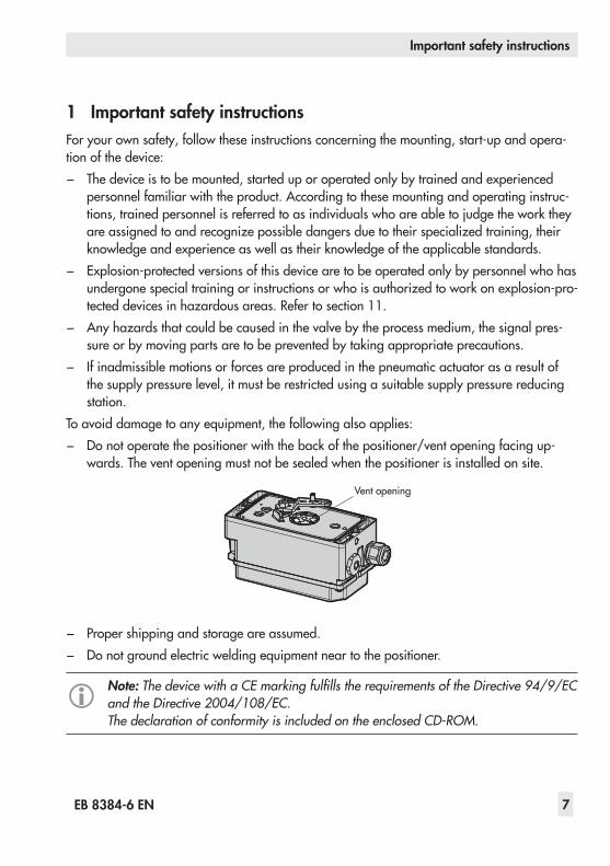
To avoid damage to any equipment, the following also applies: − Donotoperatethepositionerwiththebackofthepositioner/ventopeningfacingup-
wards. The vent opening must not be sealed when the positioner is installed on site.
Vent opening
− Proper shipping and storage are assumed. − Do not ground electric welding equipment near to the positioner.
Note: The device with a CE marking fulfills the requirements of the Directive 94/9/EC and the Directive 2004/108/EC.The declaration of conformity is included on the enclosed CD-ROM.
8 EB 8384-6 EN
Article code
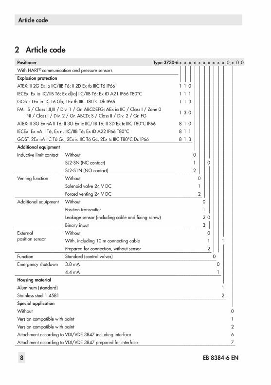
2 Article codePositioner Type 3730-6 x x x x x x x x x x 0 x 0 0WithHART® communication and pressure sensorsExplosion protectionATEX:II2GEx iaIIC/IIBT6;II2DExtbIIICT6IP66 1 1 0IECEx:Ex iaIIC/IIBT6;Exd[ia]IIC/IIBT6;ExtDA21IP66T80°C 1 1 1GOST:1Ex iaIICT6Gb;1ExtbIIICT80°CDbIP66 1 1 3FM: IS/ClassI,II,III/Div.1/Gr.ABCDEFG;AEx iaIIC/ClassI/Zone0
NI/ClassI/Div.2/Gr.ABCD;S/ClassII/Div.2/Gr.FG 1 3 0
ATEX:II3GExnAIIT6;II3GEx icIIC/IIBT6;II3DExtcIIICT80°CIP66 8 1 0IECEx:ExnAIIT6,ExnLIIC/IIBT6;ExtDA22IP66T80°C 8 1 1GOST:2ExnAIICT6Gc;2Ex icIICT6Gc;2ExtcIIICT80°CDcIP66 8 1 3Additional equipmentInductive limit contact Without 0
SJ2-SN(NCcontact) 1 0SJ2-S1N(NOcontact) 2
Venting function Without 0Solenoidvalve24 V DC 1Forcedventing24 V DC 2
Additional equipment Without 0Position transmitter 1Leakagesensor(includingcableandfixingscrew) 2 0Binaryinput 3
External position sensor
Without 0With,including10 mconnectingcable 1 1Prepared for connection, without sensor 2
Function Standard (control valves) 0Emergency shutdown 3.8 mA 0
4.4 mA 1Housing materialAluminum (standard) 1Stainlesssteel1.4581 2Special applicationWithout 0Version compatible with paint 1Version compatible with paint 2AttachmentaccordingtoVDI/VDE 3847includinginterface 6AttachmentaccordingtoVDI/VDE 3847preparedforinterface 7
EB 8384-6 EN 9
Design and principle of operation
3 Design and principle of oper-ation
The electropneumatic positioner is mounted on pneumatic control valves and is used to assign the valve position (controlled vari-able x)tothecontrolsignal(referencevari-able w).Thepositionercomparestheelectriccontrol signal of a control system to the travel or opening angle of the control valve and is-suesasignalpressure(outputvariable y)forthe pneumatic actuator.The positioner consists of a travel sensor sys-tem (2) proportional to resistance, an analog i/p converter (6) with a downstream air ca-pacitybooster(7)andtheelectronicswithmicrocontroller (5).Thepositionerisfittedwiththreebinarycon-tacts as standard: A fault alarm output indi-cates a fault to the control room and two configurablesoftwarelimitcontactsareusedto indicate the end positions of the valve.Thevalveposition(x)istransmittedasaei-theranangleofrotationortraveltothepick-up lever and to the travel sensor (2) and sup-plied to an analog PD controller. An A/D converter (4) transmits the position of the valve to the microcontroller (5). The PD con-troller (3) compares this actual position to the 4to20 mADCcontrolsignal(referencevariable) after it has been converted by the A/D converter (4). In case of a set point de-viation, the activation of the i/p converter (6) is changed so that the actuator of the control valve(1)ispressurizedorventedaccording-lyoverthedownstreambooster(7).This
causes the valve plug to move to the position determined by the reference variable (w).Thesupplyairissuppliedtothebooster(7)andthepressureregulator(8).Anintermedi-ateflowregulator(9)withfixedsettingsisused to purge the positioner and, at the sametime,guaranteestrouble-freeoperationof the booster. The output signal pressure supplied by the booster can be limited by software.Bothpressuresensors(23and24)monitors the supply pressure ps and the sig-nal pressure pout.ThevolumerestrictionQ(10)isusedtoopti-mizethepositioner.
The positioner is suitable for the following types of attachment using the corresponding accessories: − DirectattachmenttoSAMSONType 3277Actuator:section 4.1
− Attachment to actuators according to IEC 60534-6(NAMUR):section 4.2
− AttachmentaccordingtoVDI/VDE 3847:section 4.3
− AttachmenttoType 3510Micro-flowValve:section 4.4
− Attachment to rotary actuators acc. to VDI/VDE3845:section 4.5

10 EB 8384-6 EN
Design and principle of operation
PD
FSK%
Smm
%mm
w
x
Q
GG
SerialInterface 16
13
22
15
A2
A3
BE
A1
112
4
21
20
195
3
12 256
723
810
1
14
14
w
xy
24 V DC
9
17 18
x1)
>12 V&
24
x1) Depending on version >3.8 mA >4.4 mA
1 Control valve2 Travel sensor3 PD controller4 A/D converter5 Microcontroller6 i/p converter7 Air capacity booster8 Pressure regulator9 Flow regulator10 Volume restriction11* Inductive limit contact12* Solenoid valve13* Analog position transmitter or binary
input
14 Software limit contacts A1/A215 Fault alarm output A316 LCD17* Actuation of solenoid valve18 Electrical insulation19 D/A converter20 Communication interface21 HART® connection22* BinaryinputBI23 Pressure sensor for supply air ps
24 Pressure sensor for signal pressure pout
25* Forced venting* Options
Fig. 1: Functional diagram
EB 8384-6 EN 11
Design and principle of operation
3.1 Safety function (SIL)The safety function is based on the shutdown of the i/p converter (6). This causes the pneumatic actuator to be vented and the valvetomovetoitsfail-safeposition.
Monitoring of the input signalThe i/p converter is switched off when the input signal of the positioner at terminals +11/–12fallsbelow3.8 mAor4.4 mAde-pending on the positioner version (a signal rangeof4to20 mAisrequired).SeeFig. 20onpage 51.
Monitoring the voltage supply(version with forced venting and solenoid valveThe i/p converter and the solenoid valve (when installed) are shut down whenever the voltageatterminals+81/–82fallsbelow12 V(aninputvoltageof24 VDCisre-quired).SeeFig. 20onpage 51.
Whenthei/pconverterisswitchedoffaspart of the monitoring of the input signal or thevoltagesupply,thefail-safepositionS is activated and is indicated on the positioner display.If required, the user can check the safety function using the software.Details on EXPERTplus Valve Diagnostics in the Operating Instructions u EB 8389-1 EN.
3.2 Valve diagnosticsThe EXPERTplus valve diagnostics are inte-grated into the positioner. They provide in-formation on the control valve and generate status messages, which allow faults to be pinpointedquickly.Details on EXPERTplus Valve Diagnostics in the Operating Instructions u EB 8389-1 EN.

12 EB 8384-6 EN
Design and principle of operation
3.3 CommunicationThe positioner is equipped with an interface for HART® protocol (Highway Addressable Remote Transducer) for communication pur-poses. Data are transmitted in a superim-posedfrequency(FSK=FrequencyShiftKey-ing)ontheexistingsignalloopforthe4to20 mAreferencevariable.Either a HART® capable handheld communi-catororacomputerwithFSKmodemcanbeused to establish communication and oper-ate the positioner.
3.4 Configuration using the TROVIS-VIEW software
ThepositionercanbeconfiguredwithSAM-SON'sTROVIS-VIEWConfigurationandOperatorInterface(version4).Forthispur-pose, the positioner has a digital interface (SSP)toallowtheRS-232orUSBportofacomputer to be connected to it over an adapter cable.TheTROVIS-VIEWsoftwareenablestheusertoeasilyconfigurethepositioneraswellasview process parameters online.
Note:TROVIS-VIEW can be downloaded free of charge from our website at http:\\www.samson.de > Services > Software > TROVIS-VIEW.
3.5 Additional equipmentInductive limit contactIn this version, the rotary shaft of the posi-tionercarriesanadjustabletagwhichactu-atesthebuilt-inproximityswitch.Theoption-al inductive contact (11) is connected to A1, while the remaining software limit contact is connected to A2.
Solenoid valveIf the operating voltage for the solenoid valve(12)fallsbelow12 V,thesupplypres-sure for the booster is vented to the atmo-sphere. As a result, the actuator is vented andthecontrolvalvemovestothefail-safeposition. In manual mode, the manual set point is reset to 0 %. A different manual set point must entered again.
Forced ventingIfthevoltagesignalatterminals+81/–82fallsbelow12 V,thei/pconverter(6)isde-energized.Thepositionerventstheactua-tor,causingvalvetomovetothefail-safepo-sition determined by the actuator, indepen-dent of the reference variable.
Analog position transmitterThepositiontransmitter(13)isatwo-wiretransmitter and issues the travel sensor signal asa4to20 mAsignalprocessedbythemi-crocontroller. Since this signal is issued inde-pendent of the positioner’s input signal, the momentary travel/angle of rotation is con-trolledinreal-time.Additionally,thepositiontransmitter allows positioner faults to be indi-
EB 8384-6 EN 13
Design and principle of operation
catedoverasignalcurrentof<2.4 mAor>21.6 mA.
Leakage sensorByupgradingthepositionerwithaleakagesensor,itispossibletodetectseatleakagewhen the valve is in the closed position. De-tailsonEXPERTplusValveDiagnosticsintheOperatingInstructionsuEB 8389-1 EN.
Binary inputTheoptionalbinaryinputcanbeconfigured: − Toconnectafloatingcontact − Toconnectanon-floatingcontact(0to24 V DC)
Byselectingacertainfunction,oneofthefollowing actions can be activated: − Transmit switching state
The switching state of the binary input is logged.
− Activate local write protectionAfterthefirstinitialization,alocalwriteprotection can be activated.Whilethebinaryinputisactive,noset-tings can be changed at the positioner. Thepositionercannotbere-initialized.EnablingconfigurationoverCode3isnot active ( ).
− SwitchAUTO/MANThe positioner changes from the auto-matic mode (AUTO)tothemanualmode (MAN)orviceversa.This function is not performed if the posi-tionerisinthefail-safepositionmode(SAFE).
− Various diagnostic functionsDetailsonEXPERTplusValveDiagnosticsintheOperatingInstructions u EB 8389-1 EN.
Additionally,theexternalsolenoidvalvefunctioncanbeselectedifanon-floatingcontactisconfigured: − ExternalsolenoidvalveThevoltageforanexternalsolenoidvalve is connected in parallel to terminals +31/–32.Thisallowstheswitchingstateof the solenoid valve to be monitored.
Note:The optional binary input can only be configured using the operator software e.g. TROVIS-VIEW. The switching state is transmitted when the switch is closed by default.
External position sensorIn this version, only the sensor is mounted to the control valve. The positioner is located separately from the valve. The connection of xandysignalstothevalveisestablishedbycable and piping for air.

14 EB 8384-6 EN
Design and principle of operation
3.6 Technical dataType3730-6Positioner(technicaldataintestcertificatesadditionallyapplytoexplosion-protecteddevices)Travel Adjustable DirectattachmenttoType 3277Actuator: 3.6to30 mm
AttachmentaccordingtoIEC 60534-6-1: 3.6to200 mmAttachmentaccordingtoVDI/VDE3847: 3.6to200 mmRotaryactuators: 24to100°openingangle
Travel range Adjustable Adjustablewithintheinitializedtravel/angleofrotation;travelcanberestrictedto1/5atthemaximum
Reference variable w
Signal range 4to20 mA·Two-wiredevice,reversepolarityprotectionMinimumspan4 mAStatic destruction limit 30 V
Minimumcurrent 3.6 mAfordisplay·Emergencyventingat≤3.8 mAor≤4.4 mAdependingonver-sion
Load impedance ≤9.2 V(correspondingto460 Ωat20mA)Supply air Supply air 1.4to7 bar(20to105 psi)
Air quality acc. toISO8573-1(edition2001-02)
Maximumparticlesizeanddensity:Class4·Oilcontent:Class3Pressuredewpoint:Class3oratleast10 Kbelowthelowestambienttemperaturetobeexpected
Signal pressure (output) 0baruptothecapacityofthesupplypressure·Canbelimitedbetween1.4and7.0 barbysoftware
Characteris-tic
Adjustable Linear/equal percentage/reverse equal percentageUser-defined(overoperatorsoftware)Butterflyvalve,rotaryplugvalveandsegmentedballvalve:Linear/equalpercent-age
Deviation ≤1 %Hysteresis ≤0.3 %Sensitivity ≤0.1 %Transit time Fillingwithairorventingadjustableseparatelyupto240 sbysoftwareDirection of action ReversibleAir consumption, steady state Independentofsupplyairapprox.110 ln/hAir output capacity
Actuatorfilledwith air AtΔp=6bar: 8.5mn³/h·AtΔp=1.4bar:3.0mn³/h·KVmax(20°C)=0.09
Actuator vented AtΔp=6bar:14.0mn³/h·AtΔp=1.4bar:4.5mn³/h·KVmax(20°C)=0.15Permissible ambient temperature –20to+80°Cforallversions
–45to+80 °Cwithmetalcablegland–25to+80°Cwithinductivelimitcontact(SJ2-S1N)andmetalcableglandThelimitsinthetypeexaminationcertificateadditionallyapplyforexplosion-pro-tected versions.
Influences Temperature ≤0.15%/10 KSupply air NoneEffect of vibration ≤0.25%upto2000Hzand4gaccordingtoIEC 770

EB 8384-6 EN 15
Design and principle of operation
Type3730-6Positioner(technicaldataintestcertificatesadditionallyapplytoexplosion-protecteddevices)Electromagnetic com-patibility
ComplyingwithEN61000-6-2,EN61000-6-3,EN61326-1andNAMURRecom-mendationNE21
Electrical connections OneM20x1.5cableglandfor6to12 mmclampingrange·SecondM20 x 1.5threadedconnectionadditionallyexists·Screwterminalsfor0.2to2.5 mm²wirecross-sections
Degree of protection IP 66/NEMA 4XUseinsafety-instrumentedsystems according to IEC 61508/SIL
Suitableforuseinsafety-instrumentedsystemsuptoSIL 2(singledevice/HFT = 0)andSIL 3(redundantconfiguration/HFT = 1)accordingtoIEC 61511.• Triggered by the set point, emergency venting depending on positioner ver-
sionat≤3.8 mAor≤4.4 mA• Bytheoptionalsolenoidvalve,emergencyventingat0 V• Bytheoptionalforcedventing,emergencyventingat<12 V
Communication (local) SAMSONSSPinterfaceandserialinterfaceadapter,softwarerequirement(SSP):TROVIS-VIEWwithdatabasemodule3730-6
Communication (HART®) HART®fieldcommunicationsprotocol·ImpedanceinHART® frequency range: Re-ceiving350to450 Ω·Sendingapprox.115 Ω
Software re-quirements (HART®)
For handheld communicator DevicedescriptionforType 3730-6
For PC DTMfileaccordingtospecification1.2,suitableforintegratingthedeviceintoframeapplicationsthatsupporttheuseofFDT/DTM(e.g.PACTware)
ExplosionprotectionATEX,IECEx,... Seearticlecodeinsection 2BinarycontactsTwosoftwarelimitcontacts,reversepolarityprotection,floating,configurableswitchingcharacteristicsSignal state Noresponse ≤1.0mA
Response ≥2.2mAOnefaultalarmcontact,floatingSignal state Noresponse ≥2.2 mA·Nofaultalarm
Response ≤1.0 mA·Fault alarmFor connection to NAMURswitchingamplifieracc.toEN60947-5-6MaterialsHousing Die-castaluminumENAC-AlSi12(Fe)(ENAC-44300)acc.toDIN EN 1706,chro-
matedandpowderpaintcoated·Specialversion:stainlesssteel1.4581Externalparts Stainlesssteel1.4571and1.4301Cable gland M20 x 1.5,blackpolyamideWeight Approx.1.0kg
Conformity ·

16 EB 8384-6 EN
Design and principle of operation
Options for Type 3730-6 PositionerElectronic forced venting·Approvalacc.toIEC 61508/SILInput 24 V DC·Electricalisolationandreversepolarityprotection·Staticdestructionlimit
40 V
Power consumption: I = U–5.7 V (correspondingto4.8 mAat
24 V/114 mW)3.84 kΩ
Signal'0'(noresponse) ≤12 V(emergencyventingat12V)Signal'1'(response) >19 VSolenoid valve·Approvalacc.toIEC 61508/SILInput 24 V DC·Reversepolarityprotection·Staticdestructionlimit40 V
Power consumption: I = U–5.7 V (correspondingto4.8 mAat
24 V/114 mW)3.84 kΩ
Signal'0'(noresponse) ≤12 V(emergencyventingat12V)Signal'1'(response) >19 VService life >5x10⁶ switching cyclesAnalog position transmitter Two-wiretransmitter·ElectricalisolationPower supply 12to30 V DC·Reversepolarityprotection·Staticdestructionlimit40 VOutputsignal 4 to 20 mAOperatingdirection ReversibleOperatingrange –10to+114 %Characteristic LinearHysteresis Same as positionerHigh-frequencyinfluence Same as positionerOtherinfluences Same as positionerFault alarm Canbeissuedascurrentsignal2.4±0.1 mAor21.6±0.1 mALeakage sensor·SuitableforoperationinhazardousareasTemperature range –40to+130 °CTightening torque 20±5 NmInductive limit contact Forconnectiontoswitchingamplifieracc.toEN 60947-5-6
Can be used in combination with a software limit contactSJ2-SNproximityswitch NAMURNCcontact
NAMURNOcontactExternal position sensorTravel Same as positionerCable 10m·Flexibleanddurable·WithM12x1connector·Flame-retardantacc.to
VDE 0472·Resistanttooils,lubricantsandcoolantsaswellasotheraggressivemediaPermissible ambient temperature
–60to+105 °CAlsoobservethelimitsinthetestcertificateforexplosion-protectedversions.
EB 8384-6 EN 17
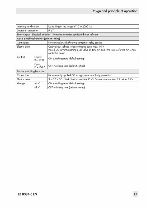
Design and principle of operation
Immunity to vibration Upto10 gintherangeof10to2000 HzDegree of protection IP 67Binaryinput·Electricalisolation·SwitchingbehaviorconfiguredoversoftwareActive switching behavior (default setting)Connection Forexternalswitch(floatingcontact)orrelaycontactElectric data Open-circuitvoltagewhencontactisopen:max.10 V
PulsedDCcurrentreachingpeakvalueof100 mAandRMSvalueof0.01 mAwhencontact is closed
Contact Closed, R<20 Ω ONswitchingstate(defaultsetting)
Open, R>400 Ω OFFswitchingstate(defaultsetting)
Passive switching behaviorConnection ForexternallyappliedDCvoltage,reversepolarityprotectionElectric data 3to30VDC·Staticdestructionlimit40 V·Currentconsumption3.7 mAat24 VVoltage >6 V ONswitchingstate(defaultsetting)
<1 V OFFswitchingstate(defaultsetting)
18 EB 8384-6 EN
Design and principle of operation
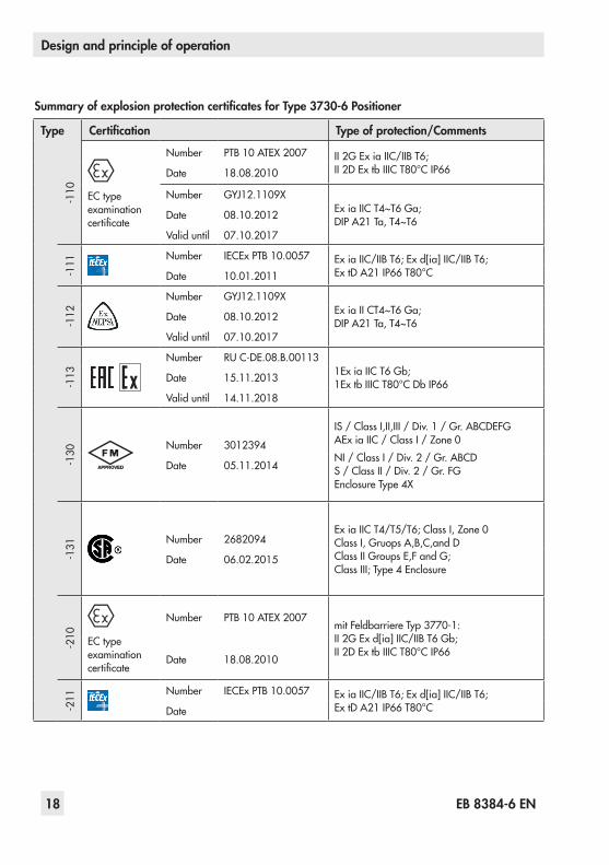
Summary of explosion protection certificates for Type 3730-6 Positioner
Type Certification Type of protection/Comments
-110 EC type
examinationcertificate
Number PTB 10ATEX2007 II2GEx iaIIC/IIBT6; II2DExtbIIICT80°CIP66Date 18.08.2010
Number GYJ12.1109XExiaIICT4~T6Ga; DIPA21Ta,T4~T6Date 08.10.2012
Valid until 07.10.2017
-111 Number IECExPTB 10.0057 Ex iaIIC/IIBT6;Exd[ia]IIC/IIBT6;
ExtDA21IP66T80°CDate 10.01.2011
-112
Number GYJ12.1109XEx iaIICT4~T6Ga; DIPA21Ta,T4~T6Date 08.10.2012
Valid until 07.10.2017
-113
Number RUC-DE.08.B.001131Ex iaIICT6Gb; 1ExtbIIICT80°CDbIP66Date 15.11.2013
Valid until 14.11.2018
-130 Number 3012394
IS/ClassI,II,III/Div.1/Gr.ABCDEFG AEx iaIIC/ClassI/Zone0NI/ClassI/Div.2/Gr.ABCD S/ClassII/Div.2/Gr.FG EnclosureType 4X
Date 05.11.2014
-131 Number 2682094
ExiaIICT4/T5/T6;ClassI,Zone0 ClassI,GruopsA,B,C,andD ClassIIGroupsE,FandG; ClassIII;Type4Enclosure
Date 06.02.2015
-210 EC type
examinationcertificate
Number PTB 10ATEX2007mitFeldbarriereTyp 3770-1: II2GEx d[ia]IIC/IIBT6Gb; II2DExtbIIICT80°CIP66
Date 18.08.2010
-211 Number IECExPTB 10.0057 Ex iaIIC/IIBT6;Exd[ia]IIC/IIBT6;
ExtDA21IP66T80°CDate
EB 8384-6 EN 19
Design and principle of operation
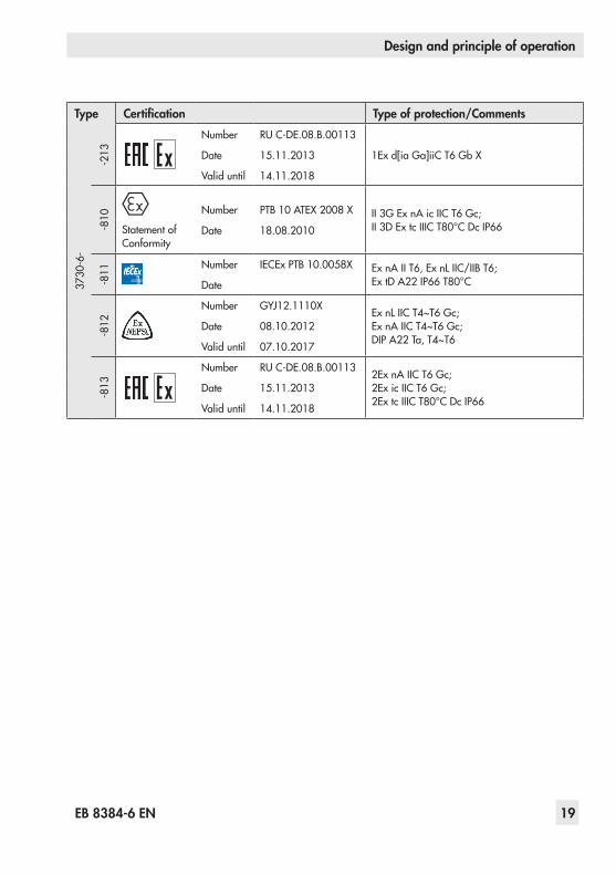
Type Certification Type of protection/Comments
3730-6-
-213
Number RUC-DE.08.B.00113
1Exd[iaGa]iiCT6GbXDate 15.11.2013
Valid until 14.11.2018
-810
Statement of Conformity
Number PTB 10ATEX2008X II3GEx nAicIICT6Gc; II3DExtcIIICT80°CDcIP66Date 18.08.2010
-811 Number IECExPTB 10.0058X ExnAIIT6,ExnLIIC/IIBT6;
ExtDA22IP66T80°CDate
-812
Number GYJ12.1110X ExnLIICT4~T6Gc; ExnAIICT4~T6Gc; DIPA22Ta,T4~T6
Date 08.10.2012
Valid until 07.10.2017
-813
Number RUC-DE.08.B.00113 2ExnAIICT6Gc; 2Ex icIICT6Gc; 2ExtcIIICT80°CDcIP66
Date 15.11.2013
Valid until 14.11.2018

20 EB 8384-6 EN
Attachment to the control valve – Mounting parts and accessories
4 Attachment to the control valve – Mounting parts and accessories
NOTICERisk of malfunction due to incorrect sequence of mounting, installation and start-up!Keep the following sequence.
1.Remove the protective film from the pneumatic connections.
2.Mount the positioner on the control valve.
3. Connect the supply air.4. Connect the electrical power.5. Perform the start-up settings.
The positioner is suitable for the following types of attachment: − DirectattachmenttoSAMSONType 3277Actuator
− Attachment to actuators according to IEC 60534-6(NAMUR)
− AttachmentaccordingtoVDI/VDE 3847 − AttachmenttoType 3510Micro-flow
Valve − Attachment to rotary actuators
NOTICERisk of malfunction due to incorrect mounting parts/accessories or incor-rect assignment of lever and pin posi-tion.Attach the positioner to the control valve only using the mounting parts and accessories as specified in Ta-ble 1 to Table 6. Observe the type of attachment.
Observe the assignment between le-ver and pin position (see travel tables on page 21).
Lever and pin positionThe positioner is adapted to the actuator and totheratedtravelbytheleveronthebackofthe positioner and the pin inserted into the lever.The travel tables on page 21 show the maximumadjustmentrangeattheposition-er. The travel that can be implemented at the valve is additionally restricted by the selected fail-safepositionandtherequiredcompres-sion of the actuator springs.ThepositionerisequippedwiththeMlever(pin position 35) as standard.
Fig. 2: M lever with pin position 35
NOTICERisk of malfunction because the newly mounted lever has not been adapted to the internal measuring le-ver.Move the newly mounted lever (1) once all the way as far as it will go in both directions.
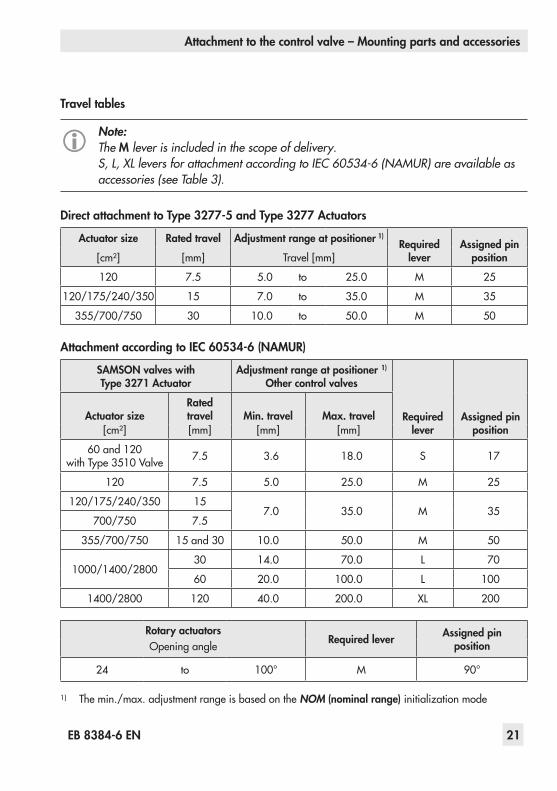
Travel tables
Note:The M lever is included in the scope of delivery.S, L, XL levers for attachment according to IEC 60534-6 (NAMUR) are available as accessories (see Table 3).
Direct attachment to Type 3277-5 and Type 3277 Actuators
Actuator size Rated travel Adjustment range at positioner 1)Required
leverAssigned pin
position[cm²] [mm] Travel[mm]
120 7.5 5.0 to 25.0 M 25
120/175/240/350 15 7.0 to 35.0 M 35
355/700/750 30 10.0 to 50.0 M 50
Attachment according to IEC 60534-6 (NAMUR)
SAMSON valves with Type 3271 Actuator
Adjustment range at positioner 1) Other control valves
Required lever
Assigned pin position
Actuator sizeRated travel Min. travel Max. travel
[cm²] [mm] [mm] [mm]
60 and 120 withType 3510Valve 7.5 3.6 18.0 S 17
120 7.5 5.0 25.0 M 25
120/175/240/350 15 7.0 35.0 M 35
700/750 7.5
355/700/750 15 and 30 10.0 50.0 M 50
1000/1400/280030 14.0 70.0 L 70
60 20.0 100.0 L 100
1400/2800 120 40.0 200.0 XL 200
Rotary actuatorsRequired lever Assigned pin
positionOpeningangle
24 to 100° M 90°
1) Themin./max.adjustmentrangeisbasedontheNOM (nominal range)initializationmode
EB 8384-6 EN 21
Attachment to the control valve – Mounting parts and accessories
4 Attachment to the control valve – Mounting parts and accessories
NOTICERisk of malfunction due to incorrect sequence of mounting, installation and start-up!Keep the following sequence.
1.Remove the protective film from the pneumatic connections.
2.Mount the positioner on the control valve.
3. Connect the supply air.4. Connect the electrical power.5. Perform the start-up settings.
The positioner is suitable for the following types of attachment: − DirectattachmenttoSAMSONType 3277Actuator
− Attachment to actuators according to IEC 60534-6(NAMUR)
− AttachmentaccordingtoVDI/VDE 3847 − AttachmenttoType 3510Micro-flow
Valve − Attachment to rotary actuators
NOTICERisk of malfunction due to incorrect mounting parts/accessories or incor-rect assignment of lever and pin posi-tion.Attach the positioner to the control valve only using the mounting parts and accessories as specified in Ta-ble 1 to Table 6. Observe the type of attachment.
Travel tables
Note:The M lever is included in the scope of delivery.S, L, XL levers for attachment according to IEC 60534-6 (NAMUR) are available as accessories (see Table 3).
Direct attachment to Type 3277-5 and Type 3277 Actuators
Actuator size Rated travel Adjustment range at positioner 1)Required
leverAssigned pin
position[cm²] [mm] Travel[mm]
120 7.5 5.0 to 25.0 M 25
120/175/240/350 15 7.0 to 35.0 M 35
355/700/750 30 10.0 to 50.0 M 50
Attachment according to IEC 60534-6 (NAMUR)
SAMSON valves with Type 3271 Actuator
Adjustment range at positioner 1) Other control valves
Required lever
Assigned pin position
Actuator sizeRated travel Min. travel Max. travel
[cm²] [mm] [mm] [mm]
60 and 120 withType 3510Valve 7.5 3.6 18.0 S 17
120 7.5 5.0 25.0 M 25
120/175/240/350 15 7.0 35.0 M 35
700/750 7.5
355/700/750 15 and 30 10.0 50.0 M 50
1000/1400/280030 14.0 70.0 L 70
60 20.0 100.0 L 100
1400/2800 120 40.0 200.0 XL 200
Rotary actuatorsRequired lever Assigned pin
positionOpeningangle
24 to 100° M 90°
1) Themin./max.adjustmentrangeisbasedontheNOM (nominal range)initializationmode
22 EB 8384-6 EN
Attachment to the control valve – Mounting parts and accessories
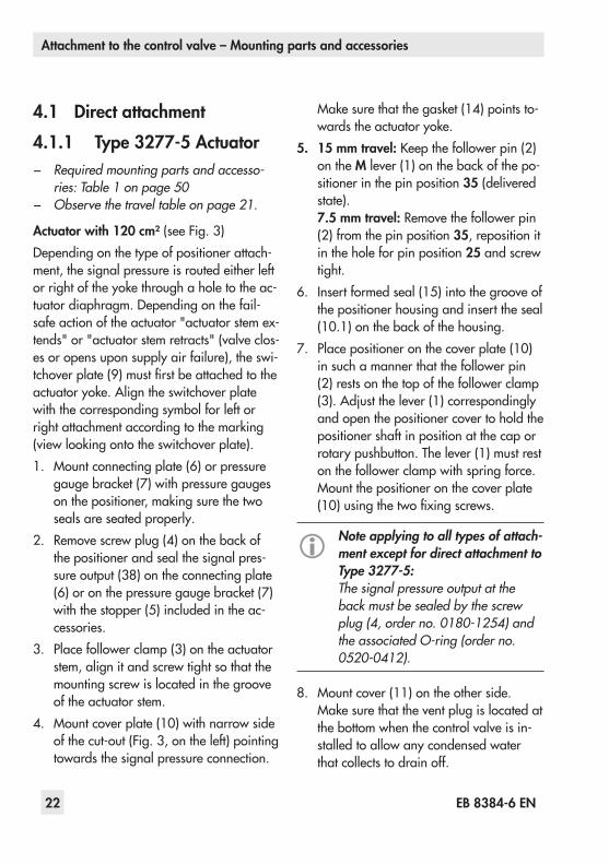
4.1 Direct attachment4.1.1 Type 3277-5 Actuator − Required mounting parts and accesso-
ries: Table 1 on page 50 − Observe the travel table on page 21.
Actuator with 120 cm² (seeFig. 3)Depending on the type of positioner attach-ment, the signal pressure is routed either left orrightoftheyokethroughaholetotheac-tuatordiaphragm.Dependingonthefail-safeactionoftheactuator"actuatorstemex-tends" or "actuator stem retracts" (valve clos-es or opens upon supply air failure), the swi-tchoverplate(9)mustfirstbeattachedtotheactuatoryoke.Aligntheswitchoverplatewith the corresponding symbol for left or rightattachmentaccordingtothemarking(viewlookingontotheswitchoverplate).1. Mountconnectingplate(6)orpressure
gaugebracket(7)withpressuregaugesonthepositioner,makingsurethetwoseals are seated properly.
2. Removescrewplug(4)onthebackofthe positioner and seal the signal pres-sureoutput(38)ontheconnectingplate(6)oronthepressuregaugebracket(7)with the stopper (5) included in the ac-cessories.
3. Place follower clamp (3) on the actuator stem, align it and screw tight so that the mounting screw is located in the groove of the actuator stem.
4. Mountcoverplate(10)withnarrowsideofthecut-out(Fig. 3,ontheleft)pointingtowards the signal pressure connection.
Makesurethatthegasket(14)pointsto-wardstheactuatoryoke.
5. 15 mm travel:Keepthefollowerpin(2)on the Mlever(1)onthebackofthepo-sitioner in the pin position 35 (delivered state).7.5 mm travel: Remove the follower pin (2) from the pin position 35, reposition it in the hole for pin position 25 and screw tight.
6. Insert formed seal (15) into the groove of the positioner housing and insert the seal (10.1)onthebackofthehousing.
7. Place positioner on the cover plate (10) in such a manner that the follower pin (2) rests on the top of the follower clamp (3).Adjustthelever(1)correspondinglyand open the positioner cover to hold the positioner shaft in position at the cap or rotary pushbutton. The lever (1) must rest on the follower clamp with spring force. Mountthepositioneronthecoverplate(10)usingthetwofixingscrews.
Note applying to all types of attach-ment except for direct attachment to Type 3277-5:The signal pressure output at the back must be sealed by the screw plug (4, order no. 0180-1254) and the associated O-ring (order no. 0520-0412).
8. Mountcover(11)ontheotherside.Makesurethattheventplugislocatedatthe bottom when the control valve is in-stalled to allow any condensed water that collects to drain off.
SymbolsActuator stem
extends
Actuator stem retracts
Left attachment Right attachment
Switchoverplate(9)
9 11
Supply 9 Output 38
56
4
7
6
1010.1
3
2
1
15
6.1
1.11.2
14
8
Marking
Signal pressure input for left attachment
Signal pressure input for right attachment
Cut-outof cover plate
NOTICEOnly use the connecting plate (6) in-cluded in the accessories to connect supply and output!Never screw threaded parts directly into housing!
1 Lever 1.1 Nut 1.2 Diskspring 2 Follower pin 3 Follower clamp 4 Screw plug 5 Sealing plug 6 Connecting plate 6.1 Seals 7 Pressuregaugebracket 8 Pressure gauge
mountingkit 9 Switchover plate
(actuator)10 Cover plate10.1 Seal11 Cover14 Gasket15 Formed seal
Fig. 3: Direct attachment – Signal pressure connection for Type 3277-5 Actuator with 120 cm²

EB 8384-6 EN 23
Attachment to the control valve – Mounting parts and accessories
4.1 Direct attachment4.1.1 Type 3277-5 Actuator − Required mounting parts and accesso-
ries: Table 1 on page 50 − Observe the travel table on page 21.
Actuator with 120 cm² (seeFig. 3)Depending on the type of positioner attach-ment, the signal pressure is routed either left orrightoftheyokethroughaholetotheac-tuatordiaphragm.Dependingonthefail-safeactionoftheactuator"actuatorstemex-tends" or "actuator stem retracts" (valve clos-es or opens upon supply air failure), the swi-tchoverplate(9)mustfirstbeattachedtotheactuatoryoke.Aligntheswitchoverplatewith the corresponding symbol for left or rightattachmentaccordingtothemarking(viewlookingontotheswitchoverplate).1. Mountconnectingplate(6)orpressure
gaugebracket(7)withpressuregaugesonthepositioner,makingsurethetwoseals are seated properly.
2. Removescrewplug(4)onthebackofthe positioner and seal the signal pres-sureoutput(38)ontheconnectingplate(6)oronthepressuregaugebracket(7)with the stopper (5) included in the ac-cessories.
3. Place follower clamp (3) on the actuator stem, align it and screw tight so that the mounting screw is located in the groove of the actuator stem.
4. Mountcoverplate(10)withnarrowsideofthecut-out(Fig. 3,ontheleft)pointingtowards the signal pressure connection.
SymbolsActuator stem
extends
Actuator stem retracts
Left attachment Right attachment
Switchoverplate(9)
9 11
Supply 9 Output 38
56
4
7
6
1010.1
3
2
1
15
6.1
1.11.2
14
8
Marking
Signal pressure input for left attachment
Signal pressure input for right attachment
Cut-outof cover plate
NOTICEOnly use the connecting plate (6) in-cluded in the accessories to connect supply and output!Never screw threaded parts directly into housing!
1 Lever 1.1 Nut 1.2 Diskspring 2 Follower pin 3 Follower clamp 4 Screw plug 5 Sealing plug 6 Connecting plate 6.1 Seals 7 Pressuregaugebracket 8 Pressure gauge
mountingkit 9 Switchover plate
(actuator)10 Cover plate10.1 Seal11 Cover14 Gasket15 Formed seal
Fig. 3: Direct attachment – Signal pressure connection for Type 3277-5 Actuator with 120 cm²
Mlever
24 EB 8384-6 EN
Attachment to the control valve – Mounting parts and accessories
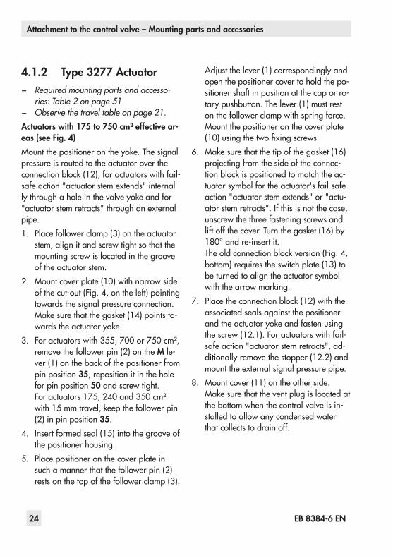
4.1.2 Type 3277 Actuator − Required mounting parts and accesso-
ries: Table 2 on page 51 − Observe the travel table on page 21.
Actuators with 175 to 750 cm² effective ar-eas (see Fig. 4)Mountthepositionerontheyoke.Thesignalpressure is routed to the actuator over the connectionblock(12),foractuatorswithfail-safeaction"actuatorstemextends"internal-lythroughaholeinthevalveyokeandfor"actuatorstemretracts"throughanexternalpipe.1. Place follower clamp (3) on the actuator
stem, align it and screw tight so that the mounting screw is located in the groove of the actuator stem.
2. Mountcoverplate(10)withnarrowsideofthecut-out(Fig. 4,ontheleft)pointingtowards the signal pressure connection. Makesurethatthegasket(14)pointsto-wardstheactuatoryoke.
3. Foractuatorswith355,700or750 cm²,remove the follower pin (2) on the M le-ver(1)onthebackofthepositionerfrompin position 35, reposition it in the hole for pin position 50 and screw tight.Foractuators175,240and350 cm²with15 mmtravel,keepthefollowerpin(2) in pin position 35.
4. Insert formed seal (15) into the groove of the positioner housing.
5. Place positioner on the cover plate in such a manner that the follower pin (2) rests on the top of the follower clamp (3).
Adjustthelever(1)correspondinglyandopen the positioner cover to hold the po-sitioner shaft in position at the cap or ro-tary pushbutton. The lever (1) must rest on the follower clamp with spring force.Mountthepositioneronthecoverplate(10)usingthetwofixingscrews.
6. Makesurethatthetipofthegasket (16)projectingfromthesideoftheconnec-tionblockispositionedtomatchtheac-tuatorsymbolfortheactuator'sfail-safeaction"actuatorstemextends"or"actu-ator stem retracts". If this is not the case, unscrew the three fastening screws and liftoffthecover.Turnthegasket(16)by180°andre-insertit.Theoldconnectionblockversion(Fig. 4,bottom) requires the switch plate (13) to be turned to align the actuator symbol withthearrowmarking.
7. Placetheconnectionblock(12)withtheassociated seals against the positioner andtheactuatoryokeandfastenusingthescrew(12.1).Foractuatorswithfail-safe action "actuator stem retracts", ad-ditionally remove the stopper (12.2) and mounttheexternalsignalpressurepipe.
8. Mountcover(11)ontheotherside.Makesurethattheventplugislocatedatthe bottom when the control valve is in-stalled to allow any condensed water that collects to drain off.
ExtendsRetracts
2
10 1415
1 2 3 11 11.1
SUPPLY
13
B
C
1.11.2
12
12.1
12
12.2
12.11216
16 16
12.2SUPPLY
View A
View B
View C
SUPPLY
G
G 3/8
A
Mlever
Cut-outof cover plate (10)
Actuatorstemextends
Actuator stem retracts
Connection block(old)withswitch plate (13)
Actuator stem
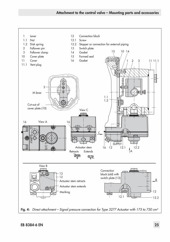
1 Lever 1.1 Nut 1.2 Diskspring 2 Follower pin 3 Follower clamp10 Cover plate11 Cover11.1 Vent plug
12 Connectionblock12.1 Screw12.2 Stopperorconnectionforexternalpiping13 Switch plate14 Gasket15 Formed seal16 Gasket
Fig. 4: Direct attachment – Signal pressure connection for Type 3277 Actuator with 175 to 750 cm²
EB 8384-6 EN 25
Attachment to the control valve – Mounting parts and accessories
4.1.2 Type 3277 Actuator − Required mounting parts and accesso-
ries: Table 2 on page 51 − Observe the travel table on page 21.
Actuators with 175 to 750 cm² effective ar-eas (see Fig. 4)Mountthepositionerontheyoke.Thesignalpressure is routed to the actuator over the connectionblock(12),foractuatorswithfail-safeaction"actuatorstemextends"internal-lythroughaholeinthevalveyokeandfor"actuatorstemretracts"throughanexternalpipe.1. Place follower clamp (3) on the actuator
stem, align it and screw tight so that the mounting screw is located in the groove of the actuator stem.
2. Mountcoverplate(10)withnarrowsideofthecut-out(Fig. 4,ontheleft)pointingtowards the signal pressure connection. Makesurethatthegasket(14)pointsto-wardstheactuatoryoke.
3. Foractuatorswith355,700or750 cm²,remove the follower pin (2) on the M le-ver(1)onthebackofthepositionerfrompin position 35, reposition it in the hole for pin position 50 and screw tight.Foractuators175,240and350 cm²with15 mmtravel,keepthefollowerpin(2) in pin position 35.
4. Insert formed seal (15) into the groove of the positioner housing.
5. Place positioner on the cover plate in such a manner that the follower pin (2) rests on the top of the follower clamp (3).
ExtendsRetracts
2
10 1415
1 2 3 11 11.1
SUPPLY
13
B
C
1.11.2
12
12.1
12
12.2
12.11216
16 16
12.2SUPPLY
View A
View B
View C
SUPPLY
G
G 3/8
A
Mlever
Cut-outof cover plate (10)
Actuatorstemextends
Actuator stem retracts
Connection block(old)withswitch plate (13)
Actuator stem
1 Lever 1.1 Nut 1.2 Diskspring 2 Follower pin 3 Follower clamp10 Cover plate11 Cover11.1 Vent plug
12 Connectionblock12.1 Screw12.2 Stopperorconnectionforexternalpiping13 Switch plate14 Gasket15 Formed seal16 Gasket
Fig. 4: Direct attachment – Signal pressure connection for Type 3277 Actuator with 175 to 750 cm²
Marking

26 EB 8384-6 EN
Attachment to the control valve – Mounting parts and accessories
4.2 Attachment according to IEC 60534-6
− Required mounting parts and accesso-ries: Table 3 on page 52
− Observe the travel table on page 21.
Fig. 5The positioner is attached to the control valve usingaNAMURbracket(10).1. Screwthetwobolts(14)tothebracket
(9.1)ofthestemconnector(9),placethefollower plate (3) on top and use the screws (14.1) for fastening.Actuator sizes 2800 cm² and 1400 cm² with 120 mm travel: − For a travel of 60 mm or smaller,
screw the longer follower plate (3.1) directlytothestemconnector(9).
− Foratravelexceeding60 mm,mountthebracket(16)firstandthenthefol-lowerplate(3)tothebrackettogeth-er with the bolts (14) and screws (14.1).
2. MountNAMURbracket(10)tothecon-trol valve as follows: − For attachment to the NAMUR rib, useanM8screw(11)andtoothedlockwasherdirectlyintheyokehole.
− For attachment to valves with rod-type yokes,usetwoU-bolts(15)aroundtheyoke.AligntheNAMURbracket(10)accordingtotheem-bossed scale so that the follower plate (3) is shifted by half the angle rangetotheNAMURbracket(theslot of the follower plate is centrally
alignedwiththeNAMURbracketatmid valve travel).
3. Mountconnectingplate(6)orpressuregaugebracket(7)withpressuregaugesonthepositioner,makingsurethetwoseals (6.1) are seated properly.
4. Selectrequiredleversize(1)M, L or XL and pin position according to the actua-torsizeandvalvetravellistedinthetrav-eltableonpage 21.
Should a pin position other than position 35 with the standard M lever be required, or an L or XLleversizeberequired,proceedasfollows:5. Screw the follower pin (2) in the as-
signed lever hole (pin position as speci-fiedinthetraveltable).Onlyusethelon-ger follower pin (2) included in the mountingkit.
6. Place the lever (1) on the shaft of the po-sitionerandfastenittightusingthediskspring (1.2) and nut (1.1).Moveleveronceallthewayasfarasitwill go in both directions.
7. PlacepositionerontheNAMURbracketin such a manner that the follower pin (2) rests in the slot of the follower plate (3,3.1).Adjustthelever(1)correspond-ingly.ScrewthepositionertotheNAMURbracketusingbothitsmountingscrews.
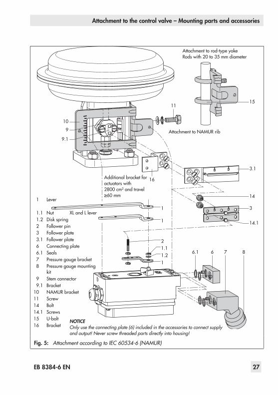
Fig. 5: Attachment according to IEC 60534-6 (NAMUR)
NOTICEOnly use the connecting plate (6) included in the accessories to connect supply and output! Never screw threaded parts directly into housing!
EB 8384-6 EN 27
Attachment to the control valve – Mounting parts and accessories
4.2 Attachment according to IEC 60534-6
− Required mounting parts and accesso-ries: Table 3 on page 52
− Observe the travel table on page 21.
Fig. 5The positioner is attached to the control valve usingaNAMURbracket(10).1. Screwthetwobolts(14)tothebracket
(9.1)ofthestemconnector(9),placethefollower plate (3) on top and use the screws (14.1) for fastening.Actuator sizes 2800 cm² and 1400 cm² with 120 mm travel: − For a travel of 60 mm or smaller,
screw the longer follower plate (3.1) directlytothestemconnector(9).
− Foratravelexceeding60 mm,mountthebracket(16)firstandthenthefol-lowerplate(3)tothebrackettogeth-er with the bolts (14) and screws (14.1).
2. MountNAMURbracket(10)tothecon-trol valve as follows: − For attachment to the NAMUR rib, useanM8screw(11)andtoothedlockwasherdirectlyintheyokehole.
− For attachment to valves with rod-type yokes,usetwoU-bolts(15)aroundtheyoke.AligntheNAMURbracket(10)accordingtotheem-bossed scale so that the follower plate (3) is shifted by half the angle rangetotheNAMURbracket(theslot of the follower plate is centrally Fig. 5: Attachment according to IEC 60534-6 (NAMUR)
NOTICEOnly use the connecting plate (6) included in the accessories to connect supply and output! Never screw threaded parts directly into housing!
10
11
1
1 14.1
3
3.1
16
15
14
11.21.12
9.1
9
6.1 6 7 8
Attachmenttorod-typeyoke Rodswith20to35 mmdiameter
AttachmenttoNAMURrib
Additionalbracketforactuators with 2800 cm²andtravel≥60 mm
XLandLlever
1 Lever
1.1 Nut 1.2 Diskspring 2 Follower pin 3 Follower plate 3.1 Follower plate 6 Connecting plate 6.1 Seals 7 Pressuregaugebracket 8 Pressure gauge mounting
kit 9 Stem connector 9.1 Bracket10 NAMURbracket11 Screw14 Bolt14.1 Screws15 U-bolt16 Bracket
28 EB 8384-6 EN
Attachment to the control valve – Mounting parts and accessories
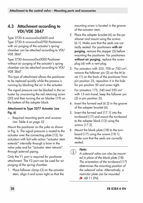
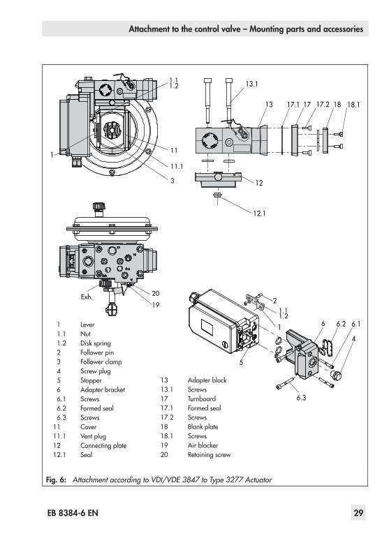
4.3 Attachment according to VDI/VDE 3847
Type3730-6-xxxxxxx0xx0600andType3730-6-xxxxxxx0xx0700Positionerswithairpurgingoftheactuator'sspringchamber can be attached according to VDI/VDE 3847.Type3730-6xxxxxxx0xx0000Positionerwithoutairpurgingoftheactuator'sspringchamber can be attached according to VDI/VDE 3847.This type of attachment allows the positioner tobereplacedquicklywhiletheprocessisrunningbyblockingtheairintheactuator.Thesignalpressurecanbeblockedintheac-tuator by unscrewing the red retaining screw (20)andthenturningtheairblocker(19)onthebottomoftheadapterblock.
Attachment to Type 3277 Actuator (see Fig. 6) − Required mounting parts and accesso-ries:Table 4onpage 52
MountthepositionerontheyokeasshowninFig. 6.Thesignalpressureisroutedtotheactuator over the connecting plate (12), for actuatorswithfail-safeaction"actuatorstemextends"internallythroughaboreinthevalveyokeandfor"actuatorstemretracts"throughexternalpiping.OnlytheY1portisrequiredforpositionerattachment.TheY2portcanbeusedforairpurging of the spring chamber.1. Place follower clamp (3) on the actuator
stem, align it and screw tight so that the
mounting screw is located in the groove of the actuator stem.
2. Placetheadapterbracket(6)onthepo-sitioner and mount using the screws (6.1).Makesurethatthesealsarecor-rectly seated. For positioners with air purging, remove the stopper (5) before mounting the positioner. For positioners without air purging, replace the screw plug (4) with a vent plug.
3. Foractuatorswith355,700or750 cm²,removethefollowerpin(2)ontheMle-ver(1)onthebackofthepositionerfrompin position 35, reposition it in the hole for pin position 50 and screw tight.Foractuators175,240and350 cm²with15 mmtravel,keepthefollowerpin(2) in pin position 35.
4. Insert the formed seal (6.2) in the groove oftheadapterbracket(6).
5. Inserttheformedseal(17.1)intotheturnboard(17)andmounttheturnboardtotheadapterblock(13)usingthescrews(17.2).
6. Mounttheblankplate(18)totheturn-board(17)usingthescrews(18.1).Makesurethatthesealsarecorrectlyseated.
Note:A solenoid valve can also be mount-ed in place of the blank plate (18). The orientation of the turnboard (17) determines the mounting position of the solenoid valve. Alternatively, a restrictor plate can be mounted (u AB 11 EN).
18.1
1
17.2 181717.1
13.1
13
12
12.1
3
11.1
11
19
20Exh.
1.11.2
1.11.2
1
2
6.2 6.16
4
6.3
5
1 Lever 1.1 Nut 1.2 Diskspring 2 Follower pin 3 Follower clamp 4 Screw plug 5 Stopper 6 Adapterbracket 6.1 Screws 6.2 Formed seal 6.3 Screws11 Cover11.1 Vent plug12 Connecting plate12.1 Seal
13 Adapterblock13.1 Screws17 Turnboard17.1 Formed seal17.2 Screws18 Blankplate18.1 Screws19 Airblocker20 Retaining screw
Fig. 6: Attachment according to VDI/VDE 3847 to Type 3277 Actuator
EB 8384-6 EN 29
Attachment to the control valve – Mounting parts and accessories
4.3 Attachment according to VDI/VDE 3847
Type3730-6-xxxxxxx0xx0600andType3730-6-xxxxxxx0xx0700Positionerswithairpurgingoftheactuator'sspringchamber can be attached according to VDI/VDE 3847.Type3730-6xxxxxxx0xx0000Positionerwithoutairpurgingoftheactuator'sspringchamber can be attached according to VDI/VDE 3847.This type of attachment allows the positioner tobereplacedquicklywhiletheprocessisrunningbyblockingtheairintheactuator.Thesignalpressurecanbeblockedintheac-tuator by unscrewing the red retaining screw (20)andthenturningtheairblocker(19)onthebottomoftheadapterblock.
Attachment to Type 3277 Actuator (see Fig. 6) − Required mounting parts and accesso-ries:Table 4onpage 52
MountthepositionerontheyokeasshowninFig. 6.Thesignalpressureisroutedtotheactuator over the connecting plate (12), for actuatorswithfail-safeaction"actuatorstemextends"internallythroughaboreinthevalveyokeandfor"actuatorstemretracts"throughexternalpiping.OnlytheY1portisrequiredforpositionerattachment.TheY2portcanbeusedforairpurging of the spring chamber.1. Place follower clamp (3) on the actuator
stem, align it and screw tight so that the
18.1
1
17.2 181717.1
13.1
13
12
12.1
3
11.1
11
19
20Exh.
1.11.2
1.11.2
1
2
6.2 6.16
4
6.3
5
1 Lever 1.1 Nut 1.2 Diskspring 2 Follower pin 3 Follower clamp 4 Screw plug 5 Stopper 6 Adapterbracket 6.1 Screws 6.2 Formed seal 6.3 Screws11 Cover11.1 Vent plug12 Connecting plate12.1 Seal
13 Adapterblock13.1 Screws17 Turnboard17.1 Formed seal17.2 Screws18 Blankplate18.1 Screws19 Airblocker20 Retaining screw
Fig. 6: Attachment according to VDI/VDE 3847 to Type 3277 Actuator

30 EB 8384-6 EN
Attachment to the control valve – Mounting parts and accessories
7. Insert the screws (13.1) through the mid-dleholesoftheadapterblock(13).
8. Place the connecting plate (12) together with the seal (12.1) onto the screws (13.1)correspondingtothefail-safeac-tion"actuatorstemextends"or"actuatorstemretracts".Thefail-safeactionthatapplies is determined by aligning the grooveoftheadapterblock(13)withthegroove of the connecting plate (12) (Fig. 7).
Z
Z
1213
Actuator stemretractsextends
12 Connecting plate
13 Adapterblock
Fig. 7: Fail-safe position
9. Mounttheadapterblock(13)togetherwith the connecting plate (12) to the ac-tuator using the screws (13.1).
10. Insert the vent plug (11.1) into the Exh. connection.
11. Forfail-safeaction"actuatorstemex-tends",sealtheY1portwithablankingplug.Forfail-safeaction"actuatorstemre-tracts",connecttheY1porttothesignalpressure connection of the actuator.
Placepositionerontheadapterblock(13) in such a manner that the follower pin (2) rests on the top of the follower clamp(3).Adjustthelever(1)corre-spondingly and open the positioner cov-er to hold the positioner shaft in position at the cap or rotary pushbutton.The lever (1) must rest on the follower clamp with spring force.Fastenthepositionertotheadapterblock(13)usingthetwofixingscrews(6.3).Makesuretheformedseal(6.2)isprop-erly seated.
12. Mountcover(11)ontheothersidetotheyoke.Makesurethattheventplugislo-cated at the bottom when the control valve is installed to allow any condensed water that collects to drain off.

EB 8384-6 EN 31
Attachment to the control valve – Mounting parts and accessories
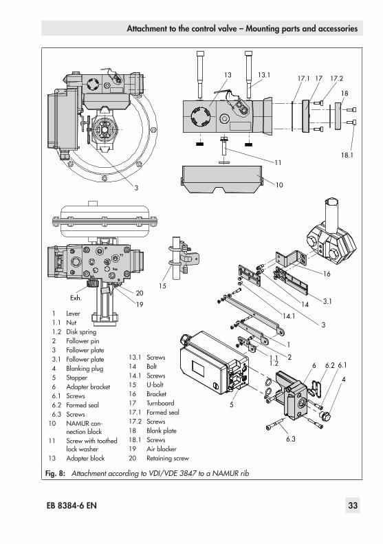
Attachment to NAMUR rib (see Fig. 8) − Required mounting parts and accesso-ries:Table 4onpage 52
− Observethetraveltableonpage 21.1. Series 240 Valves, actuator size up to
1400-60 cm²: Screw the two bolts (14) tothebracketofthestemconnectorordirectly to the stem connector (depending on the version), place the follower plate (3) on top and use the screws (14.1) to fasten it.Type 3251 Valve, 350 to 2800 cm²: Screw the longer follower plate (3.1) to thebracketofthestemconnectorordi-rectly to the stem connector (depending on the version).Type 3254 Valve, 1400-120 to 2800 cm²: Screw the two bolts (14) to thebracket(16).Fastenthebracket(16)onto the stem connector, place the follow-er plate (3) on top and use the screws (14.1) to fasten it.MountthepositionerontheNAMURribasshowninFig. 8.
2. For attachment to the NAMUR rib, fas-tentheNAMURconnectionblock(10)directlyintotheexistingyokeboreusingthescrewandtoothedlockwasher(11).AlignthemarkingontheNAMURvalveconnection(onthesidemarked'1')to50 %travel.For attachment to valves with rod-type yokes,usethetwoU-bolts(15)aroundtheyoke.FastentheNAMURconnectionblock(10)directlyintotheexistingyokeboreusingthescrewandtoothedlock
washer(11).AlignthemarkingontheNAMURvalveconnection(onthesidemarked'1')to50 %travel.
3. Placetheadapterbracket(6)onthepo-sitioner and mount using the screws (6.1).Makesurethatthesealsarecor-rectly seated. For positioners with air purging, remove the stopper (5) before mounting the positioner. For positioners without air purging, replace the screw plug (4) with a vent plug.
4. Selectrequiredleversize(1)M,LorXLand pin position according to the actua-torsizeandvalvetravellistedinthetrav-eltableonpage 21.
Should a pin position other than position 35 withthestandardMleverberequired,oranLorXLleversizeberequired,proceedasfollows: − Screw the follower pin (2) in the as-
signed lever hole (pin position as speci-fiedinthetraveltable).Onlyusethelon-ger follower pin (2) included in the mountingkit.
− Place the lever (1) on the shaft of the po-sitionerandfastenittightusingthediskspring (1.2) and nut (1.1).
− Moveleveronceallthewayasfarasitwill go in both directions.

32 EB 8384-6 EN
Attachment to the control valve – Mounting parts and accessories
5. Insert the formed seal (6.2) in the groove oftheadapterbracket.
6. Inserttheformedseal(17.1)intotheturnboard(17)andmounttheturnboardtotheadapterblock(13)usingthescrews(17.2).
7. Mounttheblankplate(18)totheturn-boardusingthescrews(18.1).Makesure that the seals are correctly seated.
Note:A solenoid valve can also be mount-ed in place of the blank plate (18). The orientation of the turnboard (17) determines the mounting position of the solenoid valve. Alternatively, a restrictor plate can be mounted (u AB 11 EN).
8. Fastentheadapterblock(13)totheNAMURconnectionblockusingthescrews (13.1).
9. InserttheventplugintotheExh.connec-tion.
10. Placethepositionerontheadapterblock(13) in such a manner that the follower pin (2) rests on the top of the follower plate(3,3.1).Adjustthelever(1)corre-spondingly.Fastenthepositionertotheadapterblock(13)usingthetwofixingscrews(6.3).Makesuretheformedseal(6.2)isprop-erly seated.
11. For single-acting actuators without air purging,connecttheY1portoftheadapterblocktothesignalpressurecon-
nectionoftheactuator.SealtheY2portwithablankingplug.For double-acting actuators and actua-tors with air purging,connecttheY2portoftheadapterblocktothesignalpressure connection of the second actua-tor chamber or spring chamber of the actuator.
6.2 6.16
4
6.3
5
1
2
16
3
3.1
11
18
18.1
13.113 17.21717.1
103
Exh.19
20
1414.1
15
1.11.2
1 Lever 1.1 Nut 1.2 Diskspring 2 Follower pin 3 Follower plate 3.1 Follower plate 4 Blankingplug 5 Stopper 6 Adapterbracket 6.1 Screws 6.2 Formed seal 6.3 Screws10 NAMURcon-
nectionblock11 Screw with toothed
lockwasher13 Adapterblock
13.1 Screws14 Bolt14.1 Screws15 U-bolt16 Bracket17 Turnboard17.1 Formed seal17.2 Screws18 Blankplate18.1 Screws19 Airblocker20 Retaining screw
Fig. 8: Attachment according to VDI/VDE 3847 to a NAMUR rib
EB 8384-6 EN 33
Attachment to the control valve – Mounting parts and accessories
5. Insert the formed seal (6.2) in the groove oftheadapterbracket.
6. Inserttheformedseal(17.1)intotheturnboard(17)andmounttheturnboardtotheadapterblock(13)usingthescrews(17.2).
7. Mounttheblankplate(18)totheturn-boardusingthescrews(18.1).Makesure that the seals are correctly seated.
Note:A solenoid valve can also be mount-ed in place of the blank plate (18). The orientation of the turnboard (17) determines the mounting position of the solenoid valve. Alternatively, a restrictor plate can be mounted (u AB 11 EN).
8. Fastentheadapterblock(13)totheNAMURconnectionblockusingthescrews (13.1).
9. InserttheventplugintotheExh.connec-tion.
10. Placethepositionerontheadapterblock(13) in such a manner that the follower pin (2) rests on the top of the follower plate(3,3.1).Adjustthelever(1)corre-spondingly.Fastenthepositionertotheadapterblock(13)usingthetwofixingscrews(6.3).Makesuretheformedseal(6.2)isprop-erly seated.
11. For single-acting actuators without air purging,connecttheY1portoftheadapterblocktothesignalpressurecon-
6.2 6.16
4
6.3
5
1
2
16
3
3.1
11
18
18.1
13.113 17.21717.1
103
Exh.19
20
1414.1
15
1.11.2
1 Lever 1.1 Nut 1.2 Diskspring 2 Follower pin 3 Follower plate 3.1 Follower plate 4 Blankingplug 5 Stopper 6 Adapterbracket 6.1 Screws 6.2 Formed seal 6.3 Screws10 NAMURcon-
nectionblock11 Screw with toothed
lockwasher13 Adapterblock
13.1 Screws14 Bolt14.1 Screws15 U-bolt16 Bracket17 Turnboard17.1 Formed seal17.2 Screws18 Blankplate18.1 Screws19 Airblocker20 Retaining screw
Fig. 8: Attachment according to VDI/VDE 3847 to a NAMUR rib
34 EB 8384-6 EN
Attachment to the control valve – Mounting parts and accessories
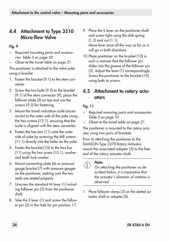
4.4 Attachment to Type 3510 Micro-flow Valve
Fig. 9 − Required mounting parts and accesso-
ries: Table 3 on page 52 − Observe the travel table on page 21.Thepositionerisattachedtothevalveyokeusingabracket.1. Fastenthebracket(9.1)tothestemcon-
nector.2. Screwthetwobolts(9.2)tothebracket
(9.1)ofthestemconnector(9),placethefollower plate (3) on top and use the screws(9.3)forfastening.
3. Mountthetravelindicationscale(acces-sories)totheoutersideoftheyokeusingthehexscrews(12.1),ensuringthatthescale is aligned with the stem connector.
4. Fastenthehexbar(11)ontotheoutersideofyokebyscrewingtheM8screws(11.1)directlyintotheholesontheyoke.
5. Fastenthebracket(10)tothehexbar(11)usingthehexscrew(10.1),washerandtoothlockwasher.
6. Mountconnectingplate(6)orpressuregaugebracket(7)withpressuregaugesonthepositioner,makingsurethetwoseals are seated properly.
7. UnscrewthestandardMlever(1)includ-ing follower pin (2) from the positioner shaft.
8. TaketheSlever(1)andscrewthefollow-erpin(2)intheholeforpinposition17.
9. Place the S lever on the positioner shaft andscrewtightusingthediskspring(1.2) and nut (1.1).Moveleveronceallthewayasfarasitwill go in both directions.
10. Placepositioneronthebracket(10)insuch a manner that the follower pin slides into the groove of the follower pin (3).Adjustthelever(1)correspondingly.Screwthepositionertothebracket(10)using both its screws.
4.5 Attachment to rotary actu-ators
Fig. 11 − Required mounting parts and accessories:
Table 5 on page 53 − Observe the travel table on page 21.
The positioner is mounted to the rotary actu-atorusingtwopairsofbrackets.Prior to attaching the positioner to the SAMSONType 3278RotaryActuator,mount the associated adapter (5) to the free end of the rotary actuator shaft.
Note:On attaching the positioner as de-scribed below, it is imperative that the actuator's direction of rotation is observed.
1. Place follower clamp (3) on the slotted ac-tuator shaft or adapter (5).
S lever
NOTICEOnly use the connecting plate (6) in-cluded in the accessories to connect supply and output!Never screw threaded parts directly into housing!
1 Lever 1.1 Nut 1.2 Diskspring 2 Follower pin 3 Follower plate 6 Connecting plate 6.1 Seals 7 Pressure gauge
bracket 8 Pressure gauge
mountingkit 9 Stem connector 9.1 Bracket
9.2 Bolt 9.3 Screws10 Bracket10.1 Screw11 Hexagonbar11.1 Screws12.1 Screws
10.1
1
2
1.1
1.2
6.1
6
78
10
9
9.1
11 11.1
3
12.1
9.2
9.3
Fig. 9: Attachment to Type 3510 Micro-flow Valve

EB 8384-6 EN 35
Attachment to the control valve – Mounting parts and accessories
4.4 Attachment to Type 3510 Micro-flow Valve
Fig. 9 − Required mounting parts and accesso-
ries: Table 3 on page 52 − Observe the travel table on page 21.Thepositionerisattachedtothevalveyokeusingabracket.1. Fastenthebracket(9.1)tothestemcon-
nector.2. Screwthetwobolts(9.2)tothebracket
(9.1)ofthestemconnector(9),placethefollower plate (3) on top and use the screws(9.3)forfastening.
3. Mountthetravelindicationscale(acces-sories)totheoutersideoftheyokeusingthehexscrews(12.1),ensuringthatthescale is aligned with the stem connector.
4. Fastenthehexbar(11)ontotheoutersideofyokebyscrewingtheM8screws(11.1)directlyintotheholesontheyoke.
5. Fastenthebracket(10)tothehexbar(11)usingthehexscrew(10.1),washerandtoothlockwasher.
6. Mountconnectingplate(6)orpressuregaugebracket(7)withpressuregaugesonthepositioner,makingsurethetwoseals are seated properly.
7. UnscrewthestandardMlever(1)includ-ing follower pin (2) from the positioner shaft.
8. TaketheSlever(1)andscrewthefollow-erpin(2)intheholeforpinposition17.
S lever
NOTICEOnly use the connecting plate (6) in-cluded in the accessories to connect supply and output!Never screw threaded parts directly into housing!
1 Lever 1.1 Nut 1.2 Diskspring 2 Follower pin 3 Follower plate 6 Connecting plate 6.1 Seals 7 Pressure gauge
bracket 8 Pressure gauge
mountingkit 9 Stem connector 9.1 Bracket
9.2 Bolt 9.3 Screws10 Bracket10.1 Screw11 Hexagonbar11.1 Screws12.1 Screws
10.1
1
2
1.1
1.2
6.1
6
78
10
9
9.1
11 11.1
3
12.1
9.2
9.3
Fig. 9: Attachment to Type 3510 Micro-flow Valve

36 EB 8384-6 EN
Attachment to the control valve – Mounting parts and accessories
2. Placecouplingwheel(4)withflatsidefacing the actuator on the follower clamp (3).RefertoFig. 11toalignslotsothatitmatches the direction of rotation when the valve is in its closed position.
3. Fasten the coupling wheel (4) and follow-er clamp (3) tightly onto the actuator shaft usingscrew(4.1)anddiskspring(4.2).
4. Fastenthebottompairofbrackets(10.1)with the bends pointing either facing to the inside or to the outside (depending on theactuatorsize)ontotheactuatorhous-ing.Positionthetoppairofbrackets(10)and fasten.
5. Mountconnectingplate(6)orpressuregaugebracket(7)withpressuregaugesonthepositioner,makingsurethetwoseals are seated properly. Double-acting springless rotary actuators require the use ofareversingamplifierontheconnection
side of the positioner housing (see section 4.6).
6. Unscrewthestandardfollowerpin(2)fromthepositioner'sMlever(1).Usethemetalfollowerpin(Ø5 mm)includedinthemountingkitandscrewtightintothehole for pin position 90°.
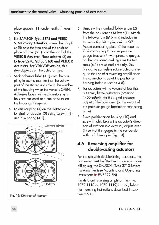
7. Placepositioneronthetopbracket(10)andfastentight.Takingtheactuator'sdi-rectionofrotationintoaccount,adjustle-ver (1) so that it engages in the slot of the coupling wheel (4) with its follower pin (Fig. 11).Itmustbeguaranteedthatthelever (1) is parallel to the long side of the positioner when the actuator is at half its angle of rotation.
8. Stickthescaleplate(4.3)onthecouplingwheel so that the arrow tip indicates the closed position and it can be easily read when the valve is installed.
4.5.1 Heavy-duty versionFig. 12 − Required mounting parts and accesso-
ries: Table 5 on page 53Bothmountingkitscontainallthenecessarymounting parts. The parts for the actuator sizeusedmustbeselectedfromthemount-ingkit.Prepare actuator, and mount required adapt-er supplied by the actuator manufacturer, if necessary.1. Mountthehousing(10)ontotherotary
actuator. In case of VDI/VDE attachment,
1.2
1.11
2
4.1
4.2
53
Fig. 10: Mounting the coupling wheel on Type 3278
10
10.1
6(7, 8)
1.124.3
5
6.1
4
1.21
130 mm
80 mmNOTICEOnly use the connecting plate (6) included in the ac-cessories to connect supply and output!Never screw threaded parts directly into housing!
Legend for Fig. 10 and Fig. 11 1 Lever 1.1 Nut 1.2 Diskspring 2 Follower pin 3 Follower clamp
(Fig. 10) 4 Coupling wheel 4.1 Screw 4.2 Diskspring 4.3 Scale plate 5 Actuator shaft
AdapterforType 3278 6 Connecting plate 6.1 Seals 7 Pressuregaugebracket 8 Pressure gauge
mountingkit10 Toppairofbrackets10.1 Bottompairofbrackets
Controlvalveopenscounterclockwise
Controlvalveopensclockwise
Slot
Slot
Fig. 11: Attachment to rotary actuators

EB 8384-6 EN 37
Attachment to the control valve – Mounting parts and accessories
2. Placecouplingwheel(4)withflatsidefacing the actuator on the follower clamp (3).RefertoFig. 11toalignslotsothatitmatches the direction of rotation when the valve is in its closed position.
3. Fasten the coupling wheel (4) and follow-er clamp (3) tightly onto the actuator shaft usingscrew(4.1)anddiskspring(4.2).
4. Fastenthebottompairofbrackets(10.1)with the bends pointing either facing to the inside or to the outside (depending on theactuatorsize)ontotheactuatorhous-ing.Positionthetoppairofbrackets(10)and fasten.
5. Mountconnectingplate(6)orpressuregaugebracket(7)withpressuregaugesonthepositioner,makingsurethetwoseals are seated properly. Double-acting springless rotary actuators require the use ofareversingamplifierontheconnection
1.2
1.11
2
4.1
4.2
53
Fig. 10: Mounting the coupling wheel on Type 3278
10
10.1
6(7, 8)
1.124.3
5
6.1
4
1.21
130 mm
80 mmNOTICEOnly use the connecting plate (6) included in the ac-cessories to connect supply and output!Never screw threaded parts directly into housing!
Legend for Fig. 10 and Fig. 11 1 Lever 1.1 Nut 1.2 Diskspring 2 Follower pin 3 Follower clamp
(Fig. 10) 4 Coupling wheel 4.1 Screw 4.2 Diskspring 4.3 Scale plate 5 Actuator shaft
AdapterforType 3278 6 Connecting plate 6.1 Seals 7 Pressuregaugebracket 8 Pressure gauge
mountingkit10 Toppairofbrackets10.1 Bottompairofbrackets
Controlvalveopenscounterclockwise
Controlvalveopensclockwise
Slot
Slot
Fig. 11: Attachment to rotary actuators
38 EB 8384-6 EN
Attachment to the control valve – Mounting parts and accessories
place spacers (11) underneath, if neces-sary.
2. For SAMSON Type 3278 and VETEC S160 Rotary Actuators, screw the adapt-er (5) onto the free end of the shaft or place adapter (5.1) onto the shaft of the VETEC R Actuator. Place adapter (3) on-to Type 3278, VETEC S160 and VETEC R Actuators. For VDI/VDE version, this stepdependsontheactuatorsize.
3. Stickadhesivelabel(4.3)ontothecou-pling in such a manner that the yellow partofthestickerisvisibleinthewindowofthehousingwhenthevalveisOPEN.Adhesivelabelswithexplanatorysym-bolsareenclosedandcanbestuckonthe housing, if required.
4. Fasten coupling (4) on the slotted actua-tor shaft or adapter (3) using screw (4.1) anddiskspring(4.2).
5. Unscrewthestandardfollowerpin(2)fromthepositioner'sMlever(1).Attachthefollowerpin(Ø5 mm)includedinthemountingkittopinposition90°.
6. Mountconnectingplate(6)forrequiredG ¼connectingthreadorpressuregaugebracket(7)withpressuregaugesonthepositioner,makingsurethetwoseals (6.1) are seated properly. Dou-ble-actingspringlessrotaryactuatorsre-quiretheuseofareversingamplifieronthe connection side of the positioner housing(refertosection 4.6).
7. For actuators with a volume of less than 300cm³,fittherestriction(orderno.1400-6964)intothesignalpressureoutput of the positioner (or the output of thepressuregaugebracketorconnectingplate).
8. Place positioner on housing (10) and screwittight.Takingtheactuator'sdirec-tionofrotationintoaccount,adjustlever(1) so that it engages in the correct slot withitsfollowerpin(Fig. 13).
4.6 Reversing amplifier for double-acting actuators
Fortheusewithdouble-actingactuators,thepositionermustbefittedwithareversingam-plifier,e.g.theSAMSONType 3710Revers-ingAmplifier(seeMountingandOperatingInstructions u EB 8392 EN).Ifadifferentreversingamplifier(itemno.1079-1118or1079-1119)isused,followthe mounting instructions described in sec-tion 4.6.1.
66.178
11.11.2
2
4.1
3
10.1
10
11
5
4.344.2
4.1
3
5.1
5
10.1
10
4.344.2
1 Lever1.1 Nut1.2 Diskspring2 Follower pin3 Adapter4 Coupling4.1 Screw4.2 Diskspring4.3 Adhesive label5 Actuator shaft or
adapter5.1 Adapter
6 Connecting plate (onlyforG ¼)
6.1 Seals 7 Pressure gauge
bracket 8 Pressure gauge
mountingkit10 Adapter housing10.1 Screws11 Spacer
SAMSON Type 3278VETEC S160, VETEC R
Attachment acc. to VDE/VDI 3845 (Sept. 2010) fixing level 1, AA1 to AA4 size (see section 15.1)
Fit restriction into signal pressure outputforactuatorswith<300 cm³volume
Fig. 12: Attachment to rotary actuators (heavy-duty version)
1
10
4
Counterclockwise
Clockwise
Fig. 13: Direction of rotation

EB 8384-6 EN 39
Attachment to the control valve – Mounting parts and accessories
place spacers (11) underneath, if neces-sary.
2. For SAMSON Type 3278 and VETEC S160 Rotary Actuators, screw the adapt-er (5) onto the free end of the shaft or place adapter (5.1) onto the shaft of the VETEC R Actuator. Place adapter (3) on-to Type 3278, VETEC S160 and VETEC R Actuators. For VDI/VDE version, this stepdependsontheactuatorsize.
3. Stickadhesivelabel(4.3)ontothecou-pling in such a manner that the yellow partofthestickerisvisibleinthewindowofthehousingwhenthevalveisOPEN.Adhesivelabelswithexplanatorysym-bolsareenclosedandcanbestuckonthe housing, if required.
4. Fasten coupling (4) on the slotted actua-tor shaft or adapter (3) using screw (4.1) anddiskspring(4.2).
66.178
11.11.2
2
4.1
3
10.1
10
11
5
4.344.2
4.1
3
5.1
5
10.1
10
4.344.2
1 Lever1.1 Nut1.2 Diskspring2 Follower pin3 Adapter4 Coupling4.1 Screw4.2 Diskspring4.3 Adhesive label5 Actuator shaft or
adapter5.1 Adapter
6 Connecting plate (onlyforG ¼)
6.1 Seals 7 Pressure gauge
bracket 8 Pressure gauge
mountingkit10 Adapter housing10.1 Screws11 Spacer
SAMSON Type 3278VETEC S160, VETEC R
Attachment acc. to VDE/VDI 3845 (Sept. 2010) fixing level 1, AA1 to AA4 size (see section 15.1)
Fit restriction into signal pressure outputforactuatorswith<300 cm³volume
Fig. 12: Attachment to rotary actuators (heavy-duty version)
1
10
4
Counterclockwise
Clockwise
Fig. 13: Direction of rotation
40 EB 8384-6 EN
Attachment to the control valve – Mounting parts and accessories
The following applies to all reversing am-plifiers:The signal pressure of the positioner is sup-pliedattheoutput1ofthereversingamplifi-er. An opposing pressure, which equals the requiredsupplypressure(Z)whenaddedtothe pressure at output 1, is applied at output 2.The following relationship applies: Output 1 + Output 2 = Supply pressure (Z).Connect output 1 to the loading pressure connection on the actuator that causes the valve to open when the pressure rises.Connect output 2 to the loading pressure connection on the actuator that causes the valve to close when the pressure rises.
Î SetslideswitchonpositionertoAIRTOOPEN.
Note:How the outputs are marked depends on the reversing amplifier used: − Type 3710:Output 1/2 = Y1/Y2 − 1079-1118and1079-1119: Output 1/2 = A1/A2
4.6.1 Reversing amplifier (1079-1118 or 1079-1119)
Fig. 141. Mounttheconnectingplate(6)fromthe
accessoriesinTable 5tothepositioner.MakesurethatbothO-rings(6.1)areseated correctly.
2. Thread the special nuts (1.3) from the ac-cessoriesofthereversingamplifierintothe boreholes of the connecting plate.
3. Insertthegasket(1.2)intotherecessofthereversingamplifierandslideboththehollowed special screws (1.1) into the connecting boreholes A1 and Z.
4. Placethereversingamplifierontotheconnecting plate (6) and screw tight us-ing both the special screws (1.1).
5. Useascrewdriver(8 mmwide)toscrewtheenclosedfilters(1.6)intotheconnec-tion boreholes A1 and Z.
NOTICEAir can escape uncontrolled from the signal pressure connection.Do not unscrew the sealing plug (1.5) out of the reversing amplifier.
Note:The rubber seal (1.4) is not required and can be removed when the seal-ing plug is used.
6. Afterinitialization,setCode 16(Pressurelimit)toNo.
Pressure gauge attachmentThemountingsequenceshowninFig. 14re-mains unchanged. Screw a pressure gauge bracketontotheconnectionsA1 and Z.
Pressure gauge bracket
G ¼ 1400-7106¼ NPT 1400-7107
PressuregaugesforsupplyairZandoutputA1aslistedinTable 1toTable 7.
A1
1.5 1.6
1.3
6.266.1
1.2 1.1 1 1.6
Z
A2
1.4
A1 A2
Z
A1
Output 38 Supply 9
Out
put 3
8Su
pply
9
1.3 1.21.1
From the positioner
Control signals to the actuator
1 Reversingamplifier1.1 Special screws1.2 Gasket1.3 Special nuts1.4 Rubber seal1.5 Sealing plug1.6 Filter
6 Connecting plate6.1 O-rings6.2 Screws
Fig. 14: Mounting a reversing amplifier (1079-1118 or 1079-1119)
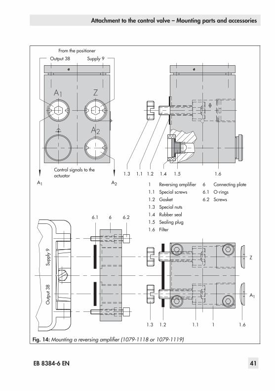
EB 8384-6 EN 41
Attachment to the control valve – Mounting parts and accessories
The following applies to all reversing am-plifiers:The signal pressure of the positioner is sup-pliedattheoutput1ofthereversingamplifi-er. An opposing pressure, which equals the requiredsupplypressure(Z)whenaddedtothe pressure at output 1, is applied at output 2.The following relationship applies: Output 1 + Output 2 = Supply pressure (Z).Connect output 1 to the loading pressure connection on the actuator that causes the valve to open when the pressure rises.Connect output 2 to the loading pressure connection on the actuator that causes the valve to close when the pressure rises.
Î SetslideswitchonpositionertoAIRTOOPEN.
Note:How the outputs are marked depends on the reversing amplifier used: − Type 3710:Output 1/2 = Y1/Y2 − 1079-1118and1079-1119: Output 1/2 = A1/A2
4.6.1 Reversing amplifier (1079-1118 or 1079-1119)
Fig. 141. Mounttheconnectingplate(6)fromthe
accessoriesinTable 5tothepositioner.MakesurethatbothO-rings(6.1)areseated correctly.
A1
1.5 1.6
1.3
6.266.1
1.2 1.1 1 1.6
Z
A2
1.4
A1 A2
Z
A1
Output 38 Supply 9
Out
put 3
8Su
pply
9
1.3 1.21.1
From the positioner
Control signals to the actuator
1 Reversingamplifier1.1 Special screws1.2 Gasket1.3 Special nuts1.4 Rubber seal1.5 Sealing plug1.6 Filter
6 Connecting plate6.1 O-rings6.2 Screws
Fig. 14: Mounting a reversing amplifier (1079-1118 or 1079-1119)

42 EB 8384-6 EN
Attachment to the control valve – Mounting parts and accessories
4.7 Attachment of external po-sition sensor
Positioner unit with sensor mounted on a mi-cro-flow valve
− Required mounting parts and accesso-ries: Table 7 on page 54
Inthepositionerversionwithanexternalpo-sition sensor, the sensor located in a separate housingisattachedoveraplateorbrackettothecontrolvalve.Thetravelpick-offcorre-sponds to that of a standard device.The positioner can be mounted as required to a wall or a pipe.For the pneumatic connection either a con-nectingplate(6)orapressuregaugebracket(7)mustbefixedtothehousing,dependingontheaccessorychosen.Makesuretheseals(6.1)arecorrectlyinserted(seeFig. 5,bot-tom right).For the electrical connectiona10 metercon-nectingleadwithM12x1connectorsisin-cluded in the scope of delivery.
Note: − In addition, the instructions in sec-tions 5.1 and 5.2 apply for the pneumatic and electrical connec-tion.
Operation and setting are described in sections 7 and 8. − Since 2009, the back of the posi-tion sensor (20) is fitted with two pins acting as mechanical stops for the lever (1). If this position sensor is mounted using old mounting parts, two corresponding Ø 8 mm holes must be drilled into the mounting plate/bracket (21). A template is available for this pur-pose. See Table 7.
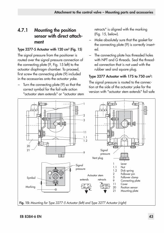
EB 8384-6 EN 43
Attachment to the control valve – Mounting parts and accessories
4.7.1 Mounting the position sensor with direct attach-ment
Type 3277-5 Actuator with 120 cm² (Fig. 15)The signal pressure from the positioner is routed over the signal pressure connection of theconnectingplate(9,Fig. 15left)totheactuator diaphragm chamber. To proceed, firstscrewtheconnectingplate(9)includedintheaccessoriesontotheactuatoryoke. − Turntheconnectingplate(9)sothatthecorrectsymbolforthefail-safeaction"actuatorstemextends"or"actuatorstem
retracts"isalignedwiththemarking(Fig. 15,below).
− Makeabsolutelysurethatthegasketfortheconnectingplate(9)iscorrectlyinsert-ed.
− The connecting plate has threaded holes withNPTandGthreads.Sealthethread-ed connection that is not used with the rubber seal and square plug.
Type 3277 Actuator with 175 to 750 cm²:The signal pressure is routed to the connec-tionatthesideoftheactuatoryokefortheversionwith"actuatorstemextends"fail-safe
2021
9
11
1.11.2
3
2
1
Actuator stemextends retracts
Signal pressure
Signal pressure
Vent plug
Symbol
Marking
1 Lever1.1 Nut1.2 Diskspring2 Follower pin3 Follower clamp9 Connecting plate11 Cover20 Position sensor21 Mountingplate
Fig. 15: Mounting for Type 3277-5 Actuator (left) and Type 3277 Actuator (right)

44 EB 8384-6 EN
Attachment to the control valve – Mounting parts and accessories
action.Forthefail-safeaction"actuatorstemretracts" the connection on the top dia-phragm case is used. The connection at the sideoftheyokemustbefittedwithaventingplug (accessories).
Mounting the position sensor1. Place the lever (1) on the sensor in
mid-positionandholditinplace.Un-thread the nut (1.1) and remove the lever togetherwiththediskspring(1.2)fromthe sensor shaft.
2. Screw the position sensor (20) onto the mounting plate (21).
3. Dependingontheactuatorsizeandrat-ed valve travel, determine which lever and position of the follower pin (2) is to be used from the travel table on page 21.Thepositionerisdeliveredwith the M lever in pin position 35 on the sensor. If necessary, remove the follower pin (2) from its pin position and move it to the hole for the recommended pin po-sition and screw tight.
4. Placethelever(1)anddiskspring(1.2)on the sensor shaft. Place the lever in mid-position and hold it in place. Screw on the nut (1.1).
5. Place follower clamp (3) on the actuator stem, align it and screw tight so that the mounting screw is located in the groove of the actuator stem.
6. Place the mounting plate together with thesensorontotheactuatoryokesothatthe follower pin (2) rests on the top of the follower clamp (3). It must rest on it with spring force. Fasten the mounting plate
(21)ontotheactuatoryokeusingbothfixingscrews.
7. Mountcover(11)ontheotherside.Makesurethattheventplugislocatedatthe bottom when the control valve is in-stalled to allow any condensed water that collects to drain off.
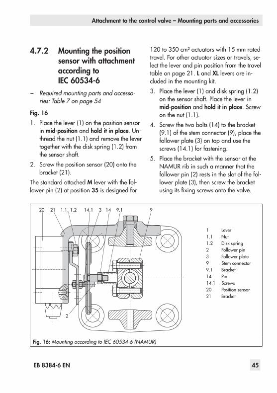
EB 8384-6 EN 45
Attachment to the control valve – Mounting parts and accessories
4.7.2 Mounting the position sensor with attachment according to IEC 60534-6
− Required mounting parts and accesso-ries: Table 7 on page 54
Fig. 161. Place the lever (1) on the position sensor
in mid-position and hold it in place.Un-thread the nut (1.1) and remove the lever togetherwiththediskspring(1.2)fromthe sensor shaft.
2. Screw the position sensor (20) onto the bracket(21).
The standard attached M lever with the fol-lower pin (2) at position 35 is designed for
120to350 cm²actuatorswith15 mmratedtravel.Forotheractuatorsizesortravels,se-lect the lever and pin position from the travel tableonpage 21.L and XL levers are in-cludedinthemountingkit.3. Placethelever(1)anddiskspring(1.2)
on the sensor shaft. Place the lever in mid-position and hold it in place. Screw on the nut (1.1).
4. Screwthetwobolts(14)tothebracket(9.1)ofthestemconnector(9),placethefollower plate (3) on top and use the screws (14.1) for fastening.
5. PlacethebracketwiththesensorattheNAMURribinsuchamannerthatthefollower pin (2) rests in the slot of the fol-lowerplate(3),thenscrewthebracketusingitsfixingscrewsontothevalve.
20 21
2
1.1, 1.2 14.1 3 14 99.1
1 Lever1.1 Nut1.2 Diskspring2 Follower pin3 Follower plate9 Stem connector9.1 Bracket14 Pin14.1 Screws20 Position sensor21 Bracket
Fig. 16: Mounting according to IEC 60534-6 (NAMUR)

46 EB 8384-6 EN
Attachment to the control valve – Mounting parts and accessories
4.7.3 Mounting the position sensor to Type 3510 Mi-cro-flow Valve
− Required mounting parts and accesso-ries: Table 7 on page 54
Fig. 171. Place the lever (1) on the position sen-
sor in mid-position and hold it in place. Unscrewthenut(1.1)andremovethestandard attached M lever (1) together withthediskspring(1.2)fromthesen-sor shaft.
2. Screw the position sensor (20) onto the bracket(21).
3. Select the S lever (1) from the accessories and screw the follower pin (2) into the
hole for pin position 17. Place the lever (1)anddiskspring(1.2)onthesensorshaft.Placetheleverinmid-positionandhold it in place. Screw on the nut (1.1).
4. Place follower clamp (3) on the valve stem connector, align at a right angle and screw tight.
5. Positionthebracket(21)withthepositionsensoronthevalveyokeandscrewtight,makingsurethefollowerpin(2)slidesinto the groove of the follower clamp (3).
20 211.11.2
1
3
2
1 Lever1.1 Nut1.2 Diskspring2 Follower pin3 Follower clamp20 Position sensor21 Bracket
Fig. 17: Mounting on a micro-flow valve
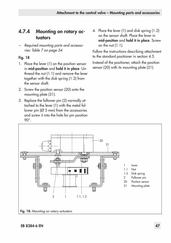
EB 8384-6 EN 47
Attachment to the control valve – Mounting parts and accessories
4.7.4 Mounting on rotary ac-tuators
− Required mounting parts and accesso-ries: Table 7 on page 54
Fig. 181. Place the lever (1) on the position sensor
in mid-position and hold it in place.Un-thread the nut (1.1) and remove the lever togetherwiththediskspring(1.2)fromthe sensor shaft.
2. Screw the position sensor (20) onto the mounting plate (21).
3. Replace the follower pin (2) normally at-tached to the lever (1) with the metal fol-lowerpin(Ø 5 mm)fromtheaccessoriesand screw it into the hole for pin position 90°.
4. Placethelever(1)anddiskspring(1.2)on the sensor shaft. Place the lever in mid-position and hold it in place. Screw on the nut (1.1).
Follow the instructions describing attachment tothestandardpositionerinsection 4.5.Instead of the positioner, attach the position sensor (20) with its mounting plate (21).
2021
2 1 1.1, 1.2
1 Lever1.1 Nut1.2 Diskspring2 Follower pin20 Position sensor21 Mountingplate
Fig. 18: Mounting on rotary actuators

48 EB 8384-6 EN
Attachment to the control valve – Mounting parts and accessories
4.8 Mounting the leakage sensor
Fig. 19Normally,thecontrolvalveisdeliveredwithpositionerandleakagesensoralreadymounted.Iftheleakagesensorismountedafterthevalve has been installed or it is mounted on-to another control valve, proceed as de-scribed in following.
NOTICERisk of malfunction due to incorrect fastening!Fasten the leakage sensor using a torque of 20 ±5 Nm.
TheM8threadedconnectionontheNAMURrib should preferably be used to mount the sensor(Fig. 19).
Tip:If the positioner was mounted directly onto the actuator (integral attach-ment), the NAMUR interfaces on ei-ther side of the valve yoke can be used to mount the leakage sensor.
Thestart-upoftheleakagesensorisde-scribedindetailintheOperatingInstructionsforEXPERTplusValveDiagnosticsu EB 8389-1 EN.
123
1 Leakagesensor2 Screw3 Plug connection
Fig. 19: Mounting the leakage sensor

EB 8384-6 EN 49
Attachment to the control valve – Mounting parts and accessories
4.9 Attaching positioners with stainless steel housings
Positioners with stainless steel housings re-quire mounting parts that are completely made of stainless steel or free of aluminum.
Note:The pneumatic connecting plate and pressure gauge bracket are available in stainless steel (order numbers listed below). The Type 3710 Pneumatic Re-versing Amplifier is also available in stainless steel.
Connecting plate(stainless steel)
G ¼¼ NPT
1400-74761400-7477
Pressure gauge bracket(stainless steel)
G ¼¼ NPT
1402-02651400-7108
Table 1toTable 6applyforattachingposi-tioners with stainless steel housings with the following restrictions:
Direct attachmentAllmountingkitsfromTable 1andTable 2canbeused.Theconnectionblockisnotre-quired. The stainless steel version of the pneu-matic connecting plate routes the air internal-ly to the actuator.
Attachment according to IEC 60534-6 (NAMUR rib or attachment to rod-type yokes)AllmountingkitsfromTable 3canbeused.Connecting plate in stainless steel.
Attachment to rotary actuatorsAllmountingkitsfromTable 5canbeusedexceptfortheheavy-dutyversion.Connect-ing plate in stainless steel.
4.10 Air purging function for sin-gle-acting actuators
The instrument air leaving from the positioner is diverted to the actuator spring chamber to provide corrosion protection inside the actua-tor. The following must be observed:
Direct attachment to Type 3277-5 (stem ex-tends FA/stem retracts FE)The air purging function is automatically provided.
Direct attachment to Type 3277, 175 to 750 cm²FA: Removethestopper(12.2,Fig. 4)atthe
blackconnectionblockandmakeapneumatic connection to the spring chamber on the vented side.
NOTICEMounting possibly incorrect when old powder-paint-coated aluminum connection blocks are used.Mount old powder-paint-coated aluminum connection blocks as described in sections on„Attach-ment according to IEC 60534-6 (NAMUR rib or attachment to rod-type yokes)“ and „Attach-ment to rotary actuators“.
FE: The air purging function is automatically provided.

50 EB 8384-6 EN
Attachment to the control valve – Mounting parts and accessories
Attachment according to IEC 60534-6 (NAMUR rib or attachment to rod-type yokes) and to rotary actuatorsThe positioner requires an additional port for theexhaustairthatcanbeconnectedoverpiping. An adapter available as an accesso-ry is used for this purpose:
Threaded bushing(M20 x 1.5)
G ¼¼ NPT
0310-26190310-2550
Note:The adapter uses one of the M20 x 1.5 connections in the hous-ing which means only one cable gland can be installed.
Should other valve accessories be used which vent the actuator (e.g. solenoid valve, volumebooster,quickexhaustvalve),thisex-haust air must also be included in the purg-ing function. The connection over the adapt-er at the positioner must be protected with a checkvalve(e.g.checkvalveG ¼,orderno.8502-0597)mountedinthepiping.Other-wise the pressure in the positioner housing would rise above the ambient pressure and damagethepositionerwhentheexhaustingcomponents respond suddenly.
4.11 Required mounting parts and accessoriesTable 1: Direct attachment to Type 3277-5 Actuator (Fig. 3) Orderno.
MountingpartsStandardversionforactuators120 cm²orsmaller 1400-7452Versioncompatiblewithpaintforactuators120 cm²orsmaller 1402-0940
Accessories for actuator
OldswitchoverplateforType3277-5xxxxxx.00 Actuator (old) 1400-6819NewswitchoverplateforType3277-5xxxxxx.01 Actuator (new) 1) 1400-6822NewconnectingplateforType3277-5xxxxxx.01 Actuator (new) 1),G 1/8 and 1/8 NPT 1400-6823
OldconnectingplateforType3277-5xxxxxx.00Actuator(old):G 1/8 1400-6820OldconnectingplateforType3277-5xxxxxx.00 (old): 1/8 NPT 1400-6821
Accessories for positioner
Connecting plate (6)G ¼ 1400-7461¼ NPT 1400-7462
Pressuregaugebracket(7)G ¼ 1400-7458¼ NPT 1400-7459
Pressuregaugemountingkit(8)uptomax.6bar (output/supply)
St. steel/brass 1400-6950St. steel/st. steel 1400-6951
1) Onlynewswitchoverandconnectingplatescanbeusedwithnewactuators(Index01).Oldandnewplatesarenot interchangeable.
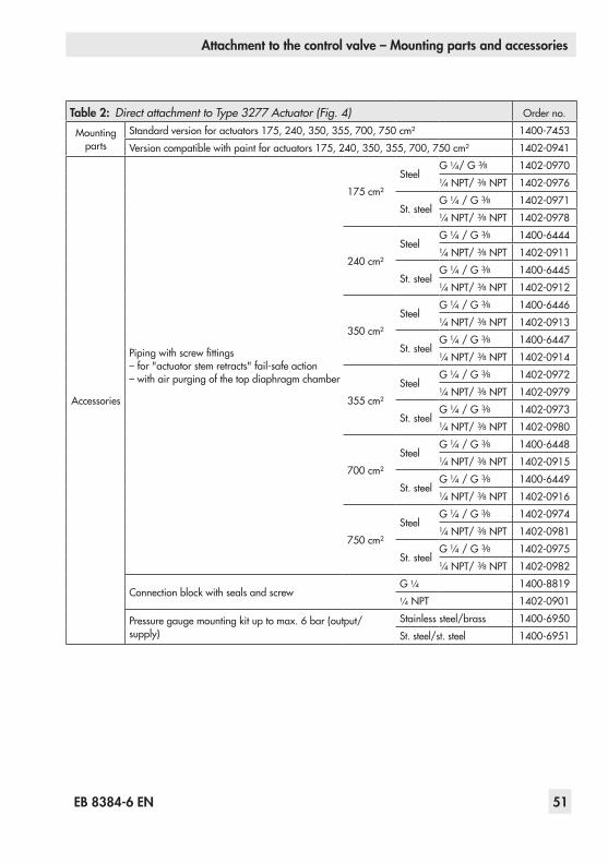
EB 8384-6 EN 51
Attachment to the control valve – Mounting parts and accessories
Table 2: Direct attachment to Type 3277 Actuator (Fig. 4) Orderno.
Mountingparts
Standardversionforactuators175,240,350,355,700,750 cm² 1400-7453Versioncompatiblewithpaintforactuators175,240,350,355,700,750 cm² 1402-0941
Accessories
Pipingwithscrewfittings–for"actuatorstemretracts"fail-safeaction–withairpurgingofthetopdiaphragmchamber
175 cm²Steel
G ¼/G 3/8 1402-0970¼ NPT/3/8 NPT 1402-0976
St. steelG ¼/G 3/8 1402-0971¼ NPT/3/8 NPT 1402-0978
240 cm²Steel
G ¼/G 3/8 1400-6444¼ NPT/3/8 NPT 1402-0911
St. steelG ¼/G 3/8 1400-6445¼ NPT/3/8 NPT 1402-0912
350 cm²Steel
G ¼/G 3/8 1400-6446¼ NPT/3/8 NPT 1402-0913
St. steelG ¼/G 3/8 1400-6447¼ NPT/3/8 NPT 1402-0914
355 cm²Steel
G ¼/G 3/8 1402-0972¼ NPT/3/8 NPT 1402-0979
St. steelG ¼/G 3/8 1402-0973¼ NPT/3/8 NPT 1402-0980
700 cm²Steel
G ¼/G 3/8 1400-6448¼ NPT/3/8 NPT 1402-0915
St. steelG ¼/G 3/8 1400-6449¼ NPT/3/8 NPT 1402-0916
750 cm²Steel
G ¼/G 3/8 1402-0974¼ NPT/3/8 NPT 1402-0981
St. steelG ¼/G 3/8 1402-0975¼ NPT/3/8 NPT 1402-0982
ConnectionblockwithsealsandscrewG ¼ 1400-8819¼ NPT 1402-0901
Pressuregaugemountingkituptomax.6bar(output/supply)
Stainless steel/brass 1400-6950St. steel/st. steel 1400-6951

52 EB 8384-6 EN
Attachment to the control valve – Mounting parts and accessories
Table 3: Attachment to NAMUR ribs or control valves with rod-type yokes (20 to 35 mm rod diameter) according to IEC 60534-6 (Fig. 5 and Fig. 9)Travel in mm Lever For actuator Orderno.7.5 S Type3271-5with60/120cm²onType 3510Micro-flowValve(Fig. 9) 1402-0478
5 to 50 M1) ActuatorsfromothermanufacturersandType 3271with120to750cm²effec-tive areas 1400-7454
14 to 100 L ActuatorsfromothermanufacturersandType3271with1000and1400-60 cm² 1400-7455
40 to 200 XL ActuatorsfromothermanufacturersandType3271with1400-120and2800 cm²andwith120 mmtravel 1400-7456
30 or 60 L
Type3271with1400-120and2800 cm²with30/60 mmtravel 1400-7466MountingbracketsforEmersonandMasoneilanlinearactuators(inaddition,amountingkitaccordingtoIEC 60534-6isrequireddependingonthetravel).See rows above.
1400-6771
ValtekType 25/50 1400-9554
Accessories
Connecting plate (6)G ¼ 1400-7461¼ NPT 1400-7462
Pressuregaugebracket(7)G ¼ 1400-7458¼ NPT 1400-7459
Pressuregaugemountingkituptomax.6bar(output/supply)Stainless steel/brass 1400-6950
St. steel/st. steel 1400-6951
1) Mleverismountedonbasicdevice(includedinthescopeofdelivery)
Table 4: Attachment according to VDI/VDE 3847 (Fig. 6 and Fig. 8)ElectropneumaticpositionerswithVDI/VDE 3847interface(Type3730-6-xxxxxxx0xx0700) Orderno.
Mountingparts
Interface adapter 1402-0257MountingkitforattachmenttoSAMSONType 3277Actuator 1402-0868MountingkitforattachmenttoSAMSONType 3271Actuatorornon-SAMSONactua-tors
1402-0869
Travelpick-offforvalvetravelupto100 mm 1402-0177Travelpick-offfor100to200 mmvalvetravel(SAMSONType 3271Actuatoronly) 1402-0178
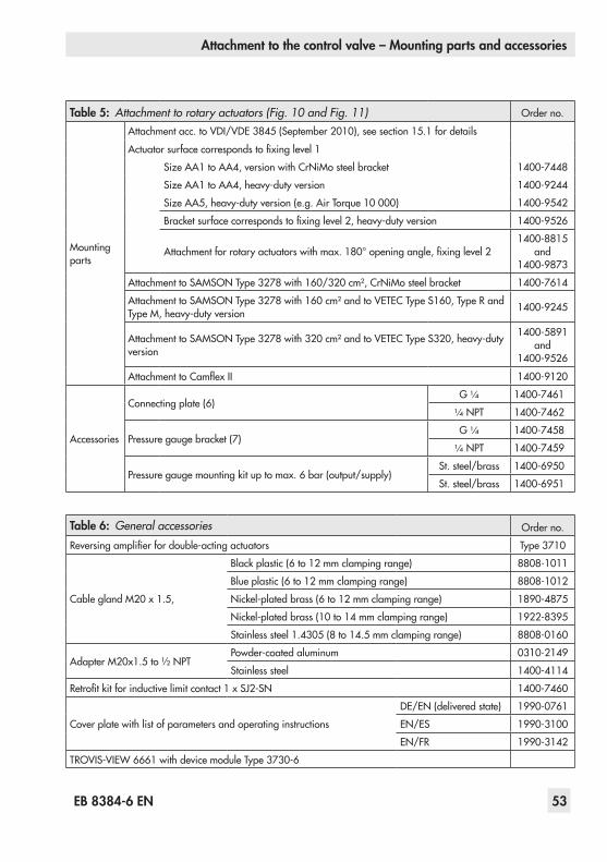
EB 8384-6 EN 53
Attachment to the control valve – Mounting parts and accessories
Table 5: Attachment to rotary actuators (Fig. 10 and Fig. 11) Orderno.
Mountingparts
Attachmentacc.toVDI/VDE3845(September2010),seesection 15.1fordetails
Actuatorsurfacecorrespondstofixinglevel1
SizeAA1toAA4,versionwithCrNiMosteelbracket 1400-7448
SizeAA1toAA4,heavy-dutyversion 1400-9244
SizeAA5,heavy-dutyversion(e.g.AirTorque10000) 1400-9542
Bracketsurfacecorrespondstofixinglevel2,heavy-dutyversion 1400-9526
Attachmentforrotaryactuatorswithmax.180°openingangle,fixinglevel21400-8815
and 1400-9873
AttachmenttoSAMSONType 3278with160/320cm²,CrNiMosteelbracket 1400-7614
AttachmenttoSAMSONType 3278with160cm²andtoVETECType S160,TypeRandTypeM,heavy-dutyversion 1400-9245
AttachmenttoSAMSONType 3278with320cm²andtoVETECType S320,heavy-dutyversion
1400-5891and
1400-9526
AttachmenttoCamflexII 1400-9120
Accessories
Connecting plate (6)G ¼ 1400-7461
¼ NPT 1400-7462
Pressuregaugebracket(7)G ¼ 1400-7458
¼ NPT 1400-7459
Pressuregaugemountingkituptomax.6bar(output/supply)St. steel/brass 1400-6950
St. steel/brass 1400-6951
Table 6: General accessories Orderno.
Reversingamplifierfordouble-actingactuators Type 3710
CableglandM20x1.5,
Blackplastic(6to12 mmclampingrange) 8808-1011
Blueplastic(6to12 mmclampingrange) 8808-1012
Nickel-platedbrass(6to12 mmclampingrange) 1890-4875
Nickel-platedbrass(10to14 mmclampingrange) 1922-8395
Stainlesssteel1.4305(8to14.5 mmclampingrange) 8808-0160
AdapterM20x1.5to½ NPTPowder-coatedaluminum 0310-2149
Stainless steel 1400-4114
Retrofitkitforinductivelimitcontact1xSJ2-SN 1400-7460
Cover plate with list of parameters and operating instructions
DE/EN(deliveredstate) 1990-0761
EN/ES 1990-3100
EN/FR 1990-3142
TROVIS-VIEW 6661withdevicemoduleType3730-6
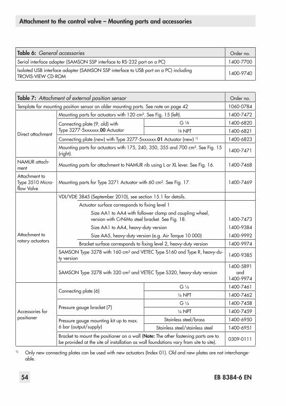
54 EB 8384-6 EN
Attachment to the control valve – Mounting parts and accessories
Table 6: General accessories Orderno.
Serialinterfaceadapter(SAMSONSSPinterfacetoRS-232portonaPC) 1400-7700
IsolatedUSBinterfaceadapter(SAMSONSSPinterfacetoUSBportonaPC)includingTROVIS-VIEWCD-ROM 1400-9740
Table 7: Attachment of external position sensor Orderno.Templateformountingpositionsensoronoldermountingparts.Seenoteonpage 42 1060-0784
Direct attachment
Mountingpartsforactuatorswith120cm².SeeFig. 15(left). 1400-7472
Connectingplate(9,old)withType 3277-5xxxxxx.00 Actuator
G 1/8 1400-68201/8 NPT 1400-6821
Connectingplate(new)withType 3277-5xxxxxx.01 Actuator (new) 1) 1400-6823Mountingpartsforactuatorswith175,240,350,355and700 cm².SeeFig. 15(right). 1400-7471
NAMURattach-ment MountingpartsforattachmenttoNAMURribusingLorXLlever.SeeFig. 16. 1400-7468
Attachment to Type 3510Micro-flowValve
MountingpartsforType 3271Actuatorwith60cm².SeeFig. 17. 1400-7469
Attachment to rotary actuators
VDI/VDE3845(September2010),seesection 15.1fordetails.Actuatorsurfacecorrespondstofixinglevel1
SizeAA1toAA4withfollowerclampandcouplingwheel,versionwithCrNiMosteelbracket.SeeFig. 18. 1400-7473SizeAA1toAA4,heavy-dutyversion 1400-9384SizeAA5,heavy-dutyversion(e.g.AirTorque10000) 1400-9992
Bracketsurfacecorrespondstofixinglevel2,heavy-dutyversion 1400-9974SAMSONType 3278with160cm²andVETECType S160andType R,heavy-du-ty version 1400-9385
SAMSONType 3278with320cm²andVETECType S320,heavy-dutyversion1400-5891
and1400-9974
Accessories for positioner
Connecting plate (6)G ¼ 1400-7461¼ NPT 1400-7462
Pressuregaugebracket(7)G ¼ 1400-7458¼ NPT 1400-7459
Pressuregaugemountingkituptomax.6 bar (output/supply)
Stainless steel/brass 1400-6950Stainless steel/stainless steel 1400-6951
Brackettomountthepositioneronawall(Note: The other fastening parts are to be provided at the site of installation as wall foundations vary from site to site). 0309-0111
1) Onlynewconnectingplatescanbeusedwithnewactuators(Index01).Oldandnewplatesarenotinterchange-able.

EB 8384-6 EN 55
Connections
5 ConnectionsWARNING!Risk of injury due to the actuator stem extending or retracting!Do not touch or block the actuator stem!
NOTICEMalfunction due to incorrect se-quence of mounting, installation and start-up.Keep the following sequence.
1. Remove the protective film from the pneumatic connections.
2. Mount the positioner on the control valve.
3.Connect the supply air.4. Connect the electrical power.5. Perform the start-up settings.
5.1 Pneumatic connections
NOTICEMalfunction due to incorrect connec-tion of the supply air.Do not connect the compressed air directly to the threaded connections in the positioner housing. Screw the screw fittings into the connecting plate, pressure gauge mounting block or connection block from the accessories.
The pneumatic connections in the connecting plate,pressuregaugemountingblockandconnectionblockareoptionallydesignedas
aborewith¼ NPTorG ¼thread.Custom-aryfittingsformetalorcoppertubingorplastic hoses can be used.
NOTICERisk of malfunction due to failure to comply with required air quality.Only use supply air that is dry and free of oil and dust.Read the maintenance instructions for upstream pressure reducing stations.Blow through all air pipes and hoses thoroughly before connecting them.
If the positioner is attached directly to the Type 3277Actuator,theconnectionofthepositioner'soutputpressuretotheactuatorisfixed.ForattachmentaccordingtoIEC 60534-6(NAMUR),thesignalpressurecan be routed to either the top or bottom di-aphragm chamber of the actuator, depend-ingontheactuator'sfail-safeaction"actua-torstemextends"or"actuatorstemretracts".Forrotaryactuators,themanufacturer'sspecificationsforconnectionapply.
5.1.1 Signal pressure gaugesTo monitor the supply air (supply) and signal pressure (output), we recommend mounting pressuregauges(seeaccessoriesinTable 2toTable 7.
5.1.2 Supply pressureThe required supply air pressure depends on thebenchrangeandtheactuator'soperat-ingdirection(fail-safeaction).
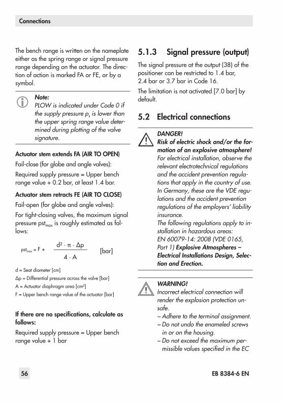
56 EB 8384-6 EN
Connections
The bench range is written on the nameplate either as the spring range or signal pressure range depending on the actuator. The direc-tionofactionismarkedFAorFE,orbyasymbol.
Note:PLOW is indicated under Code 0 if the supply pressure ps is lower than the upper spring range value deter-mined during plotting of the valve signature.
Actuator stem extends FA (AIR TO OPEN)Fail-close(forglobeandanglevalves):Requiredsupplypressure=Upperbenchrangevalue+0.2 bar,atleast1.4 bar.
Actuator stem retracts FE (AIR TO CLOSE)Fail-open(forglobeandanglevalves):Fortight-closingvalves,themaximumsignalpressure pstmax is roughly estimated as fol-lows:
pstmax= F + d²·π·∆p
[bar]4·A
d=Seatdiameter[cm]∆p=Differentialpressureacrossthevalve[bar]A=Actuatordiaphragmarea[cm²]F=Upperbenchrangevalueoftheactuator[bar]
If there are no specifications, calculate as follows:Requiredsupplypressure=Upperbenchrangevalue+1 bar
5.1.3 Signal pressure (output)Thesignalpressureattheoutput(38)ofthepositionercanberestrictedto1.4 bar,2.4 baror3.7 barinCode 16.Thelimitationisnotactivated[7.0 bar]bydefault.
5.2 Electrical connections
DANGER!Risk of electric shock and/or the for-mation of an explosive atmosphere!For electrical installation, observe the relevant electrotechnical regulations and the accident prevention regula-tions that apply in the country of use. In Germany, these are the VDE regu-lations and the accident prevention regulations of the employers’ liability insurance.The following regulations apply to in-stallation in hazardous areas: EN 60079-14: 2008 (VDE 0165, Part 1) ExplosiveAtmospheres –Electrical Installations Design, Selec-tionandErection.
WARNING!Incorrect electrical connection will render the explosion protection un-safe. − Adhere to the terminal assignment. − Do not undo the enameled screws in or on the housing. − Do not exceed the maximum per-missible values specified in the EC
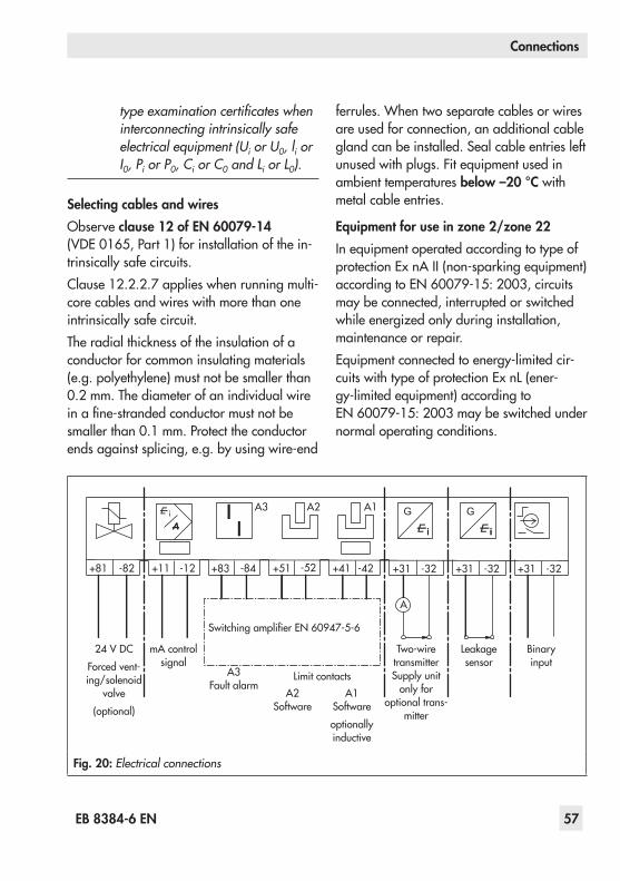
EB 8384-6 EN 57
Connections
type examination certificates when interconnecting intrinsically safe electrical equipment (Ui or U0, li or I0, Pi or P0, Ci or C0 and Li or L0).
Selecting cables and wiresObserveclause 12 of EN 60079-14 (VDE 0165,Part 1)forinstallationofthein-trinsically safe circuits.Clause 12.2.2.7applieswhenrunningmulti-core cables and wires with more than one intrinsically safe circuit.Theradialthicknessoftheinsulationofaconductor for common insulating materials (e.g. polyethylene) must not be smaller than 0.2 mm.Thediameterofanindividualwireinafine-strandedconductormustnotbesmallerthan0.1 mm.Protecttheconductorendsagainstsplicing,e.g.byusingwire-end
ferrules.Whentwoseparatecablesorwiresare used for connection, an additional cable gland can be installed. Seal cable entries left unused with plugs. Fit equipment used in ambient temperatures below –20 °C with metal cable entries.
Equipment for use in zone 2/zone 22In equipment operated according to type of protectionEx nAII(non-sparkingequipment)accordingtoEN 60079-15: 2003,circuitsmay be connected, interrupted or switched whileenergizedonlyduringinstallation,maintenance or repair.Equipmentconnectedtoenergy-limitedcir-cuitswithtypeofprotectionEx nL(ener-gy-limitedequipment)accordingtoEN 60079-15: 2003maybeswitchedundernormal operating conditions.
24 V DCForced vent-ing/solenoid
valve(optional)
mA control signal
Binaryinput
SwitchingamplifierEN60947-5-6
Two-wiretransmitter Supply unit
only for optional trans-
mitter
Leakagesensor
G
+81 -82 +11 -12 +83 -84 +51 -52
A2A3 A1
+41 -42 +31 -32
A
+31 -32
G
+31 -32
A3Fault alarm
Limit contactsA2
SoftwareA1
Softwareoptionally inductive
Fig. 20: Electrical connections

58 EB 8384-6 EN
Connections
The maximum permissible values specified in the statement of conformity and its ad-denda apply when interconnecting the equipment with energy-limited circuits in type of protection Ex nL IIC.
Cable entryCableentrywithM20 x 1.5cablegland.See section on Accessories for clamping range.ThereisasecondM20x1.5threadedholein the housing that can be used for addition-al connection, when required.The screw terminals are designed for wire cross-sectionsof0.2to2.5 mm².Tightenbyatleast0.5 Nm.The wires for the reference variable must be connected to the terminals 11 and 12 locat-ed in the housing.Onlyuseacurrent source.≥3.6 mA:Microprocessoranddisplayactive<3.7 mA:LOWreadingondisplay≤3.8 mA: Emergency shutdown (version with shutdownat3.8 mA)>3.9 mA:Actuatorcanbefilledwithair(versionwithshutdownat3.8 mA)≤4.4 mA: Emergency shutdown (version with shutdownat4.4 mA)>4.6 mA:Actuatorcanbefilledwithair(versionwithshutdownat4.4 mA)>22 mA:OVERLOADreadingondisplayIn general, it is not necessary to connect the positioner to a bonding conductor. Should this be required, however, this conductor can be connected inside the device.
Depending on the version, the positioner is equipped with inductive limit contacts and/or a solenoid valve.The position transmitter is operated on a two-wirecircuit.Theusualsupplyvoltageis24 V DC.Takingtheresistanceofthesupplyleads into account, the voltage at the posi-tion transmitter terminals can be between 12 and30 V DC.RefertoFig. 20ortothelabelonthetermi-nalblock.
AccessoriesCable glands M20 x 1.5 Orderno.Blackplastic(6to12 mmclampingrange) 8808-1011Blueplastic(6to12 mmclampingrange) 8808-1012Nickel-platedbrass(6to12 mmclampingrange) 1890-4875Nickel-platedbrass(10to14 mmclampingrange) 1922-8395Stainless steel 1.4305(8to14.5 mmclampingrange) 8808-0160
Adapter M20 x 1.5 to ½ NPTPowder-coatedaluminum 0310-2149Stainless steel 1400-7114
5.2.1 Switching amplifierFor operation of the limit contacts, switching amplifiersmustbeconnectedintheoutputcircuit. To ensure the operating reliability of thepositioner,theamplifiersshouldcomplywith the limit values of the output circuits conformingtoEN 60947-5-6.
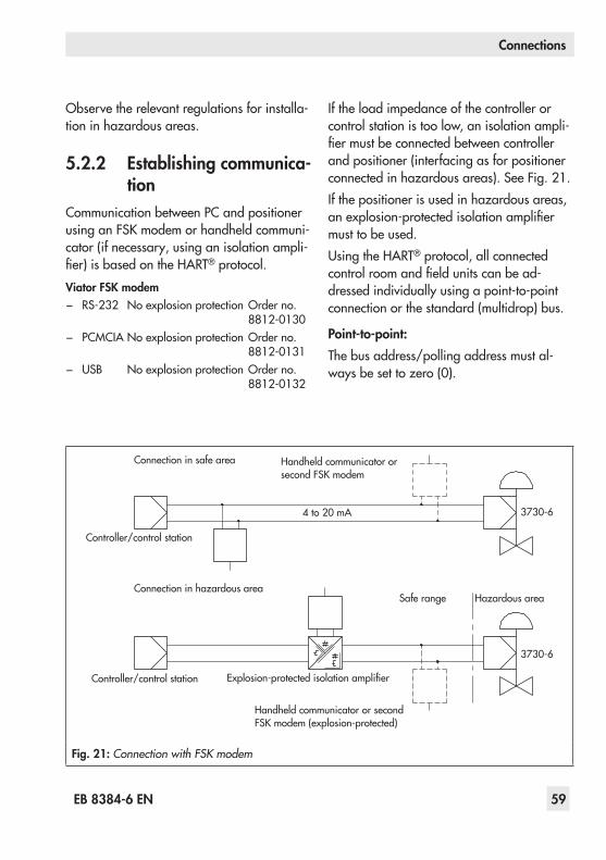
EB 8384-6 EN 59
Connections
Observetherelevantregulationsforinstalla-tioninhazardousareas.
5.2.2 Establishing communica-tion
Communication between PC and positioner usinganFSKmodemorhandheldcommuni-cator (if necessary, using an isolation ampli-fier)isbasedontheHART® protocol.Viator FSK modem
− RS-232 Noexplosionprotection Orderno.8812-0130
− PCMCIA Noexplosionprotection Orderno.8812-0131
− USB Noexplosionprotection Orderno.8812-0132
If the load impedance of the controller or control station is too low, an isolation ampli-fiermustbeconnectedbetweencontrollerand positioner (interfacing as for positioner connectedinhazardousareas).SeeFig. 21.Ifthepositionerisusedinhazardousareas,anexplosion-protectedisolationamplifiermust to be used.UsingtheHART® protocol, all connected controlroomandfieldunitscanbead-dressedindividuallyusingapoint-to-pointconnection or the standard (multidrop) bus.
Point-to-point:The bus address/polling address must al-waysbesettozero(0).
3730-6
3730-6
Connection in safe area
Connectioninhazardousarea
Controller/control station
Controller/control station
Handheld communicator or secondFSKmodem
4 to 20 mA
Explosion-protectedisolationamplifier
Handheld communicator or second FSKmodem(explosion-protected)
Safe range Hazardousarea
Fig. 21: Connection with FSK modem

60 EB 8384-6 EN
Connections
Standard bus (multidrop):In the standard bus (multidrop) mode, the positioner follows the analog current signal (reference variable) in the same manner as forpoint-to-pointcommunication.Thisoper-atingmodeis,forexample,suitableforsplit-range operation of positioners (series con-nection).The bus address/polling address has to be within a range of 1 to 15.
Note:Communication errors may occur when the process controller/control station output is not HART-compati-ble. For adaptation, the Z box (order no. 1170-2374) can be installed be-tween output and communication in-terface. At the Z box a voltage of ap-prox. 330 mV is released (corre-sponds to 16.5 Ω at 20 mA).Alternatively, a 250 Ω resistor can be connected in series and a 22 μF capacitor can be connected in paral-lel to the analog output.The following must be observed: − The load for the controller output will increase as a result. − The insertion of a capacitor is not permissible for intrinsically safe cir-cuits (Ex ia), energy-limited circuits (Ex nL) and for the type of protec-tion Ex nA.
Controller/control station
Fig. 22: Adapting the output signal
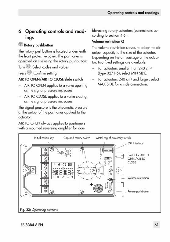
EB 8384-6 EN 61
Operating controls and readings
6 Operating controls and read-ings
Rotary pushbuttonThe rotary pushbutton is located underneath the front protective cover. The positioner is operated on site using the rotary pushbutton:Turn : Select codes and valuesPress :ConfirmsettingAIR TO OPEN/AIR TO CLOSE slide switch − AIRTOOPENappliestoavalveopening
as the signal pressure increases. − AIRTOCLOSEappliestoavalveclosing
as the signal pressure increases.The signal pressure is the pneumatic pressure at the output of the positioner applied to the actuator.AIRTOOPENalwaysappliestopositionerswithamountedreversingamplifierfordou-
ble-actingrotaryactuators(connectionsac-cordingtosection 4.6).Volume restriction QThe volume restriction serves to adapt the air outputcapacitytothesizeoftheactuator.Depending on the air passage at the actua-tor,twofixedsettingsareavailable. − Foractuatorssmallerthan240 cm²(Type 3271-5),selectMINSIDE.
− Foractuators240 cm²andlarger,selectMAXSIDEforasideconnection.
%mm
AIR TOO
PEN
CLO
SE
INIT
CA
UTIO
NVA
LVEA
CTU
ATES
MIN
SIDE
MA
X BAC
K
MIN
BAC
KM
AX SID
E Q
%S
mm
%S
mm
SERIAL
INTERFA
CE
%mm
Initializationkey Cap and rotary switch Metaltagofproximityswitch
SSP interface
SwitchforAIRTOOPEN/AIRTOCLOSE
Volume restriction
Rotary pushbutton
Fig. 23: Operating elements

62 EB 8384-6 EN
Operating controls and readings
ReadingsIcons assigned to certain codes, parameters and functions are indicated on the display.
Operating modes: − Manualmode(seesection 8.2.1)
The positioner follows the manual set point(Code 1)insteadofthemAsignal.blinks:Thepositionerisnotinitialized.
Operationonlypossibleovermanualsetpoint (Code 1).
− Automaticmode(seesection 8.2.1)Thepositionerisinclosed-loopoperationand follows the mA signal.
− S SAFE(seesection 8.2.2)The positioner vents the output. The valve movestothemechanicalfail-safeposi-tion.
Bar graph:In manual and automatic modes, the bars indicate the set point deviation that de-pendsonthesign(+/–)andthevalue.Onebarelementappearsper1 %setpointdevi-ation.Ifthepositionerhasnotbeeninitialized,( blinksonthedisplay),thebargraphindi-cates the lever position in degrees in relation tothemid-axis.Onebarelementcorre-spondstoapproximatelya5°angleofrota-tion.Thefifthbarelementblinks(reading>30°)ifthepermissibleangleofrotationhas
beenexceeded.Leverandpinpositionmustbechecked.
Status messages − Failure − Maintenancedemanded/Mainte-
nance required − blinks:Outofspecification
These icons indicate that an error has oc-curred.Aclassifiedstatuscanbeassignedtoeacherror.Classificationsinclude“Nomessage”,“Maintenancerequired”,“Maintenancede-manded”and“Failure”(seesection 14).
Enable configurationThisindicatesthatthecodesmarkedwithanasterisk(*)inthecodelist(section 14)areenabledforconfiguration(seesection 8.1).

EB 8384-6 EN 63
Operating controls and readings
Malfunction/faultManualmodeClosed-loopoperationCode
Bargraphforsetpointdeviation or lever position
Units
Fail-safepositionactive
Maintenancedemanded/Maintenancerequired
Blinks:Outofspecification Configurationenabled
DesignationPositionParameters
Limit contact alarm 1
AIR TOO
PEN
CLO
SE
INIT
CA
UTIO
NVA
LVEA
CTU
ATES
MIN
SIDE
MA
X BAC
K
MIN
BAC
KM
AX SID
E Q
SERIAL
INTERFA
CE
%
Smm
%mm
%
Smm
%mm
Limit contact alarm 2
AUTO AutomaticCL ClockwiseCCL CounterclockwiseERR ErrorESC CancelHI ixhigherthan21.6 mALO ixlowerthan2.4 mALOW wlowerthan3.7 mAMAN ManualsettingMAX MaximumrangeNo Notavailable/notactiveNOM Rated travelOVERLOAD w>22 mA
PLOW ps lower than upper spring range value
RES ResetSAFE Fail-safepositionSUB Substitute calibrationTUNE InitializationinprogressYES Available/activeZP Zerocalibration0 bar Nosupplyair
Increasing/increasing Increasing/decreasing
blinking Emergency mode (see error code 62)
blinking Positionernotinitialized
S Valveinmechanicalfail-safeposition
Failure
Maintenancedemanded/Maintenancerequired
blinks Outofspecification
blinks Writeprotectionactive(overbinaryinputoptionor HART® communication)
O/C and PST in alternating sequence Writeprotectionactive(time-controlledPST)
Fig. 24: Display

64 EB 8384-6 EN
Operating controls and readings
6.1 Serial interfaceThe positioner must be supplied with at least 3.8 mA.The positioner can be connected directly to the PC over the local serial interface and the serial interface adapter. The operator soft-wareisTROVIS-VIEW(version4)within-stalleddevicemodule3730-6.
6.2 HART® communicationThe positioner must be supplied with at least 3.6 mA.TheFSKmodemmustbeconnectedin parallel to the current loop.ADTMfile(DeviceTypeManager)conform-ingtotheSpecification1.2isavailableforcommunication. This allows the device, for example,toberunwiththePACTwareoper-atorinterface.Allthepositioner'sparame-tersarethenaccessibleovertheDTMandthe operator interface.Forstart-upandsettings,proceedasde-scribedinsection 7.1to7.4.Refertothecodelistinsection 14fortheparametersnecessary for the operator interface.
Note:If complex functions are started in the positioner, which require a long cal-culation time or lead to a large quan-tity of data being saved in the vola-tile memory of the positioner, the alert 'busy' is issued issued by the DTM file. This alert is not an error message and can be simply con-firmed.
Locking HART® communicationThe write access for HART® communication canbedisabledoverCode 47.Thisfunctioncan only be enabled or disabled locally at the positioner.Writeaccessisenabledbydefault.
Locking on-site operationTheon-siteoperationincludingtheINITkeycanbelockedoverHART® communication. Theword'HART'thenblinksonthedisplaywhenCode 3isselected.Thislockingfunc-tion can only be disabled over HART® com-munication.On-siteoperationisenabledbydefault.
6.3 Dynamic HART® variablesThe HART®specificationdefinesfourdynam-ic variables consisting of a value and an en-gineering unit. These variables can be as-signed to device parameters as required. The universal HART® command 3 reads the dy-namic variables out of the device. This al-lowsmanufacturer-specificparameterstoal-so be transferred using a universal com-mand.IntheType 3730-6Positioner,thedynamicvariables can be assigned as follows in the Device settings folder (> Positioner > HART communication):
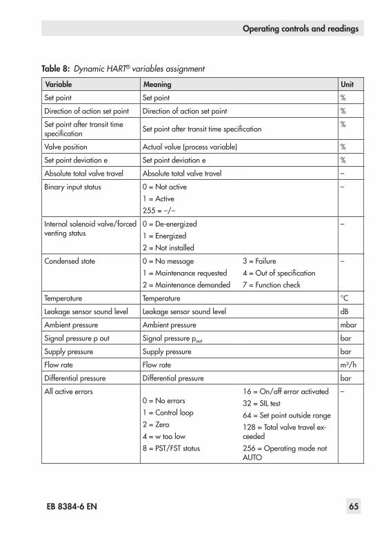
EB 8384-6 EN 65
Operating controls and readings
Table 8: Dynamic HART® variables assignment
Variable Meaning Unit
Set point Set point %
Direction of action set point Direction of action set point %
Set point after transit time specification Setpointaftertransittimespecification %
Valve position Actual value (process variable) %
Set point deviation e Set point deviation e %
Absolute total valve travel Absolute total valve travel –
Binaryinputstatus 0=Notactive1=Active255=–/–
–
Internal solenoid valve/forced venting status
0=De-energized1=Energized2=Notinstalled
–
Condensed state 0=Nomessage1=Maintenancerequested2=Maintenancedemanded
3=Failure4=Outofspecification7=Functioncheck
–
Temperature Temperature °C
Leakagesensorsoundlevel Leakagesensorsoundlevel dB
Ambient pressure Ambient pressure mbar
Signal pressure p out Signal pressure pout bar
Supply pressure Supply pressure bar
Flow rate Flow rate m³/h
Differential pressure Differential pressure bar
All active errors0=Noerrors1=Controlloop2=Zero4=wtoolow8=PST/FSTstatus
16=On/offerroractivated32=SILtest64=Setpointoutsiderange128=Totalvalvetravelex-ceeded256=OperatingmodenotAUTO
–

66 EB 8384-6 EN
Start-up and settings
7 Start-up and settings
NOTICEMalfunction due to incorrect se-quence of mounting, installation and start-up.Keep the following sequence.
1. Remove the protective film from the pneumatic connections.
2. Mount the positioner on the control valve.
3. Connect the supply air.4. Connect the electrical power.5. Perform the start-up settings.
Reading after connecting the electrical pow-er supply:blinksonthedisplaywhenthepositioner
hasnotyetbeeninitialized.Thereadingin-dicates the lever position in degrees in rela-tiontothemid-axis.
Reading when the positioner hasnotyetbeeninitialized
Code 0 appears on the display when a posi-tioner has been initialized. The positioner is in the last active operating mode.
WARNING!Risk of injury due to the actuator stem extending or retracting!Do not touch or block the actuator stem.
Note:The positioner performs a test in the start-up phase while following its au-tomation task at the same time.During the start-up phase, operation on site is unrestricted, yet write ac-cess is limited.
Performthestart-upsettingsinthesamese-quenceasdescribed(section7.1tosec-tion 7.6).
7.1 Defining the valve closed position
Definetheclosedpositionofthevalve(0 %)takingthevalvetypeandtheactuator'sdi-rection of action into account. Position the AIRTOOPEN/AIRTOCLOSEslideswitchaccordingly: − AIR TO OPEN (ATO) setting
Signal pressure opens the valve e.g. for afail-closevalveTheAIRTOOPENsettingalwaysappliestodouble-actingactuators.
− AIR TO CLOSE (ATC) settingSignal pressure closes the valve e.g. for afail-openvalve
For checking purposes: After successfully completinginitialization,thepositionerdis-playmustread0 %whenthevalveisclosedand100 %whenthevalveisopen.Ifthisisnot the case, change the slide switch position andre-initializethepositioner.
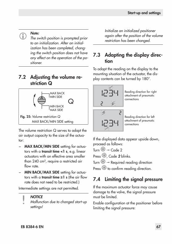
EB 8384-6 EN 67
Start-up and settings
Note:The switch position is prompted prior to an initialization. After an initial-ization has been completed, chang-ing the switch position does not have any effect on the operation of the po-sitioner.
7.2 Adjusting the volume re-striction Q
MAX BACKMIN SIDE
MIN BACKMAX SIDE
Q
Fig. 25: Volume restriction QMAXBACK/MINSIDEsetting
ThevolumerestrictionQservestoadapttheairoutputcapacitytothesizeoftheactua-tor: − MAX BACK/MIN SIDE setting for actua-
tors with a transit time <1 s, e.g. linear actuators with an effective area smaller than240 cm²,requirearestrictedairflowrate.
− MIN BACK/MAX SIDE setting for actua-tors with a transit time ≥1 s(theairflowrate does not need to be restricted.)
Intermediate settings are not permitted.
NOTICEMalfunction due to changed start-up settings!
Initialize an initialized positioner again after the position of the volume restriction has been changed.
7.3 Adapting the display direc-tion
To adapt the reading on the display to the mounting situation of the actuator, the dis-playcontentscanbeturnedby180°.
Reading direction for right attachment of pneumatic connections
Reading direction for left attachment of pneumatic connections
If the displayed data appear upside down, proceed as follows:Turn Code 2Press , Code 2blinks.Turn Required reading directionPress toconfirmreadingdirection.
7.4 Limiting the signal pressureIfthemaximumactuatorforcemaycausedamage to the valve, the signal pressure must be limited.Enableconfigurationatthepositionerbeforelimiting the signal pressure:

68 EB 8384-6 EN
Start-up and settings
Note:If no settings are entered within 120 seconds, the enabled configuration function becomes invalid.
EnableconfigurationDefault: No
Turn g Code 3, display: NoPress , Code 3blinks.Turn YESPress , display:
Limit the signal pressure:
Pressure limitDefault: No
Turn Code 16Press , Code 16blinks.Turn until the required pressure limit ap-pears.Press toconfirmthepressurelimitsetting.
7.5 Checking the operating range of the positioner
Tocheckthemechanicalattachmentandtheproper functioning, the valve should be moved through the operating range of the positioner in the manual mode with the manual set point.
Select manual mode:
OperatingmodeDefault MAN
Turn Code 0Press , Code 0blinks.Turn MANPress . The positioner changes to the man-ual mode ( ).
Check the operating range:
Manualsetpointw(current angle of rotation is indicated)
Turn Code 1Press , Code 1 and blink.Turn until the pressure in the positioner builds up, and the control valve moves to its finalpositionssothatthetravel/anglecanbechecked.Theangleofrotationoftheleveronthebackofthepositionerisindicated.Ahorizontallever(midposition)isequalto0°.To ensure the positioner is working proper-ly,theouterbarelementsmustnotblinkwhile the valve is moving through the operat-ing range.ExitCode 1bypressingtherotarypushbut-ton ( ).

EB 8384-6 EN 69
Start-up and settings
The permissible range has been exceed-ed when the displayed angle is more than30°andtheouterrightorleftbarelementblinks.Thepositionergoestothefail-safeposition(SAFE).Aftercancelingthefail-safeposition(SAFE)(seesection 8.2.2)itisabsolutely essentialthatyouchecktheleverandpinpositionasdescribedinsection 4.
WARNING!Risk of injury due to the actuator stem extending or retracting!Before exchanging the lever or changing the pin position, disconnect the supply air and electrical auxiliary power.
7.6 Initialization
NOTICEThe process is disturbed by the move-ment of the actuator stem.Do not initialize the positioner while the process is running; only perform an initialization during start-up with the shut-off valves closed.A signal pressure above the maximum permissible limit will damage the valve.Check the maximum permissible sig-nal pressure of the control valve be-fore starting initialization. If neces-sary, limit the signal pressure by con-necting an upstream pressure reduc-ing valve.
Malfunction due to changed mount-ing or installation circumstances!Reset the positioner to its default set-tings and re-initialize it after the posi-tioner has been mounted on to anoth-er actuator or its mounting location has been changed.
Note:When the write protection is acti-vated, initialization cannot be started.
Duringinitializationthepositioneradaptsitselfoptimally to the friction conditions and the sig-nal pressure required by the control valve. The typeandextentofautotuningdependsontheinitializationmodeselected: − Maximum range (MAX) (standard range)Initializationmodeforsimplestart-upofvalveswithtwoclearlydefinedmechanicalendpositions,e.g.three-wayvalves(seesection 7.6.1)
− Nominal range (NOM)Initializationmodeforallglobevalves(seesection 7.6.2)
− Manually selected OPEN position (MAN)Initializationmodeforglobevalvesrequir-ingOPENpositiontobeenteredmanually(seesection 7.6.3)
− Manually selected end positions (MAN2)Initializationmodeforglobevalveswithmanual entry of both positions (see sec-tion 7.6.4)

70 EB 8384-6 EN
Start-up and settings
− Substitute calibration (SUb)This mode allows a positioner to be re-placed while the plant is running, with the least amount of disruption to the plant (see section 7.6.5).
Note:For normal operation, simply start ini-tialization by pressing the INIT key af-ter mounting the positioner on the valve and defining the fail-safe posi-tion and setting the volume restriction. The positioner only needs to work with its default settings. If necessary, perform a reset (see section 7.8).
Alternating readingsInitializationinprogressIcon depending on initializationmodeselected
Bargraphindicatingtheprogressoftheinitialization
Afterthebasicinitialization,thereferencecurve for the valve signature is recorded (Code 48-h0=YES).
Reading in alternating sequence: TEST/D1
Bargraphdisplayindicatingtheprogressoftheinitializa-tion
% Initializationsuccessfullycom-pleted. Positioner in automatic mode ( )
Thetimerequiredfortheinitializationproce-dure depends on the actuator transit time and cantakeafewminutes.Afterasuccessfulinitialization,thepositionerrunsinclosed-loopoperationindicatedbythe closed-loopoperationicon.A malfunctioning leads to the process being canceled.Theinitializationerrorappearsonthe display according to how it has been classifiedbythecondensedstate.Seesec-tion 8.3.
Note:An error during the recording of the valve signature is indicated by Code 81.The valve signature does not affect closed-loop operation.
Closed position AIR TO CLOSEIftheslideswitchissettoAIRTOCLOSE,thepositioner automatically switches to the direc-tion of action increasing/decreasing (äæ) afterinitializationhasbeencompleted. This results in the following assignment between reference variable and valve position:
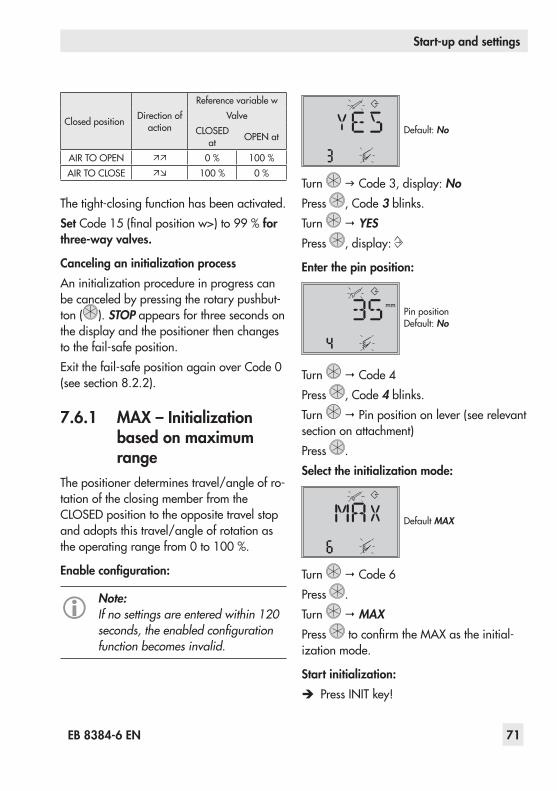
EB 8384-6 EN 71
Start-up and settings
Closed position Direction of action
Reference variable wValve
CLOSEDat OPENat
AIRTOOPEN 0 % 100 %AIRTOCLOSE 100 % 0 %
Thetight-closingfunctionhasbeenactivated.Set Code15(finalpositionw>)to99% for three-way valves.
Canceling an initialization processAninitializationprocedureinprogresscanbe canceled by pressing the rotary pushbut-ton ( ). STOP appears for three seconds on the display and the positioner then changes tothefail-safeposition.Exitthefail-safepositionagainoverCode 0(seesection 8.2.2).
7.6.1 MAX – Initialization based on maximum range
The positioner determines travel/angle of ro-tation of the closing member from the CLOSEDpositiontotheoppositetravelstopand adopts this travel/angle of rotation as theoperatingrangefrom0to100 %.
Enable configuration:
Note:If no settings are entered within 120 seconds, the enabled configuration function becomes invalid.
Default: No
Turn g Code 3, display: NoPress , Code 3blinks.Turn YESPress , display:
Enter the pin position:
mmPin positionDefault: No
Turn Code 4Press , Code 4blinks.Turn Pin position on lever (see relevant section on attachment)Press .Select the initialization mode:
Default MAX
Turn Code 6Press .Turn MAXPress toconfirmtheMAXastheinitial-izationmode.
Start initialization: Î PressINITkey!
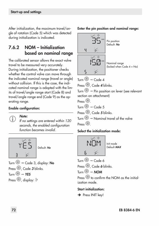
72 EB 8384-6 EN
Start-up and settings
Afterinitialization,themaximumtravel/an-gleofrotation(Code 5)whichwasdetectedduringinitializationisindicated.
7.6.2 NOM – Initialization based on nominal range
Thecalibratedsensorallowstheexactvalvetravel to be measured very accurately. Duringinitialization,thepositionercheckswhether the control valve can move through the indicated nominal range (travel or angle) without collision. If this is the case, the indi-cated nominal range is adopted with the lim-itsoftravel/anglerangestart(Code 8)andtravel/anglerangeend(Code 9)astheop-erating range.
Enable configuration:
Note:If no settings are entered within 120 seconds, the enabled configuration function becomes invalid.
Default: No
Turn g Code 3, display: NoPress , Code 3blinks.Turn YESPress , display:
Enter the pin position and nominal range:
mmPin positionDefault: No
mmNominalrange(lockedwhenCode 4=No)
Turn Code 4Press , Code 4blinks.Turn Pin position on lever (see relevant section on attachment)Press .Turn Code 5Press , Code 5blinks.Turn NominaltravelofthevalvePress .
Select the initialization mode:
Init modeDefault MAX
Turn Code 6Press , Code 6blinks.Turn NOMPress toconfirmtheNOMastheinitial-izationmode.
Start initialization: Î PressINITkey!

EB 8384-6 EN 73
Start-up and settings
Note:If the nominal range determined during initialization is smaller than the range entered in Code 5, initial-ization is canceled and an error mes-sage (Code 52) is generated.
Î Afterinitialization,checkthedirectionofaction(Code 7)and,ifnecessary,change it.
7.6.3 MAN – Initialization based on a manually selected OPEN position
Beforestartinginitialization,movethecon-trolvalvemanuallytotheOPENposition.The positioner calculates the differential trav-el/anglefromtheOPENandCLOSEDposi-tions and adopts it as the operating range with limits of lower travel/angle range value (Code 8)anduppertravel/anglerangeval-ue(Code 9).
Enable configuration:
Note:If no settings are entered within 120 seconds, the enabled configuration function becomes invalid.
EnableconfigurationDefault: No
Turn g Code 3, display: NoPress , Code 3blinks.
Turn YESPress , display:
Enter the pin position:
mmPin positionDefault: No
Turn Code 4Press , Code 4blinks.Turn Pin position on lever (see relevant section on attachment)Press .
Select the initialization mode:
Init modeDefault MAX
Turn Code 6Press , Code 6blinks.Turn MANPress toconfirmtheMAN as the initial-izationmode.
Enter OPEN position:
Manualsetpoint(current angle of rotation is indicated)
Turn Code 0Press , Code 0blinks.Turn MAN

74 EB 8384-6 EN
Start-up and settings
Press .Turn Code 1Press , Code 1blinks.Turn clockwiseinsmallstepsuntilthere-quired valve position is reached. The valve must be moved with a monotonically in-creasing signal pressure.Press toconfirmtheOPENposition.
Start initialization: Î PressINITkey!
Afterinitialization,themaximumtravelisin-dicatedinmmorthemaximumanglein°inCode 5.
7.6.4 MAN2 – Initialization based on manually se-lected end positions
Beforestartinginitialization,movethecon-trol valve manually to the end positions. The positioner calculates the travel/angle differ-ence from the positions that the valve moved to and adopts it as the operating range with limits of lower travel/angle range value (Code 8)anduppertravel/anglerangeval-ue(Code 9).
Note:This initialization mode can only be started when the valve position dif-fers in the end positions and the posi-tioner has not yet been initialized.
Enable configuration:
Note:If no settings are entered within 120 seconds, the enabled configuration function becomes invalid.
EnableconfigurationDefault: No
Turn g Code 3, display: NoPress , Code 3blinks.Turn YESPress , display:
Enter the pin position:
mmPin positionDefault: No
Turn Code 4Press , Code 4blinks.Turn Pin position on lever (see relevant section on attachment)Press .
Select the initialization mode and enter end positions:
Init modeDefault MAX

EB 8384-6 EN 75
Start-up and settings
POS1(endposition1)
POS2(endposition2)
Turn Code 6Press , Code 6blinks.Turn MAN2Press toconfirmtheMAN2 as the initial-izationmode. POS1 and the current an-gle position of the lever are indicated on the display in alternating sequence.Turn clockwiseinsmallstepsuntilthere-quired valve position is reached. The valve must be moved with a monotonically in-creasing signal pressure.Press toconfirmthevalveposition WAIT. The valve position is adopted after the pressure settles. POS2 and the current an-gle position of the lever are indicated on the display in alternating sequence.Turn untilthevalvereachesitsOPENpo-sition.Press toconfirmthevalveposition WAIT.Initializationcanbestartedassoonas MAN2 is indicated again on the display.
Start initialization: Î PressINITkey!
Afterinitialization,thetight-closingfunction(Code 14)isdeactivated.
7.6.5 SUB – Substitute calibra-tion
Acompleteinitializationproceduretakesseveral minutes and requires the valve to move through its entire travel range several times.Thisinitializationmode,however,isan emergency mode, in which the control parameters are estimated and not deter-minedbyaninitializationprocedure.Asaresult,ahighlevelofaccuracycannotbeex-pected.Youshouldalwaysselectadifferentinitializationmodeiftheplantallowsit.The substitute calibration is used to replace a positioner while the process is running. For thispurpose,thecontrolvalveisusuallyfixedmechanically in a certain position, or pneu-matically by means of a pressure signal whichisroutedtotheactuatorexternally.Theblockingpositionensuresthattheplantcontinues to operate with this valve position.Theblockingpositioncanalsobethefail-safepositionwhenthisconditionisbenefi-cial for the temporary phase.
Î Performaresetbeforere-initializingthepositioner if the substitute positioner has alreadybeeninitialized.Refertosec-tion 7.8.
Enable configuration:
Note:If no settings are entered within 120 seconds, the enabled configuration function becomes invalid.

76 EB 8384-6 EN
Start-up and settings
EnableconfigurationDefault: No
Turn g Code 3, display: NoPress , Code 3blinks.Turn YESPress , display:
Enter the pin position and nominal range:
mm Pin positionDefault: No
mmNominalrange(lockedwhenCode 4=No)
Turn Code 4Press , Code 4blinks.Turn Pin position on lever (see relevant section on attachment)Press .Turn Code 5Press , Code 5blinks.Turn NominaltravelofthevalvePress .
Select the initialization mode:
Init modeDefault MAX
Turn Code 6Press .Turn SUBPress toconfirmtheSUBastheinitializa-tion mode.
Enter the direction of action:
Direction of actionDefault
Turn Code7Press , Code 7blinks.Turn Direction of action (ää/äæ)Press .
Deactivate travel limit:
Travel limitDefault: No
Turn Code 11Press , Code 11blinks.Turn g NoPress .

EB 8384-6 EN 77
Start-up and settings
Change pressure limit and control parame-ters:
Note:Do not change the pressure limit (Code 16). Only change the control parameters KP (Code 17) and TV (Code 18) if the settings of the the re-placed positioner are known.
Pressure limitDefault: No
KP levelDefault 7
TV levelDefault 2
Turn Code16/17/18Press , Code 16/17/18blinks.Turn to set the control parameter select-ed.Press toconfirmthesetting.
Enter closing direction and blocking position:
Closing direction (direction of ro-tation causing the valve to move totheCLOSEDposition(viewon-to positioner display)Default:CCL(counterclockwise)
mm
BlockingpositionDefault 0
Turn Code 34Press , Code 34blinks.Turn Closingdirection(CCL=counter-
clockwise/CL=clockwise)Press .Turn Code 35Press , Code 35blinks.Turn Blockingposition,e.g.5 mm(read off at travel indicator scale of the blockedvalveormeasurewitharuler).
Set the fail-safe position: Î SetswitchforclosedpositionAIRTOOPENorAIRTOCLOSEaccordingtosection 7.1.
Î Set volume restriction as described in section 7.2.
Start initialization: Î PressINITkey!The operating mode is changed to auto-matic mode .
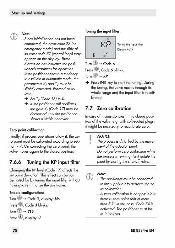
78 EB 8384-6 EN
Start-up and settings
Note: − Since initialization has not been completed, the error code 76 (no emergency mode) and possibly al-so error code 57 (control loop) may appear on the display. These alarms do not influence the posi-tioner’s readiness for operation. − If the positioner shows a tendency to oscillate in automatic mode, the parameters KP and TV must be slightly corrected. Proceed as fol-lows:
Î Set TV (Code 18) to 4. Î If the positioner still oscillates, the gain KP (Code 17) must be decreased until the positioner shows a stable behavior.
Zero point calibrationFinally,ifprocessoperationsallowit,theze-ro point must be calibrated according to sec-tion 7.7.Oncorrectingthezeropoint,thevalve moves again to the closed position.
7.6.6 Tuning the KP input filterChangingtheKPlevel(Code 17)affectstheset point deviation. This effect can be com-pensatedforbytuningtheinputfilterwithouthavingtore-initializethepositioner.
Enable configuration:Turn g Code 3, display: NoPress , Code 3blinks.Turn YESPress , display:
Tuning the input filter
TuningtheinputfilterDefault MAX
Turn Code 6Press , Code 6blinks.Turn g KP
Î PressINITkeytostartthetuning.Duringthe tuning, the valve moves through its wholerangeandtheinputfilterisrecali-brated.
7.7 Zero calibrationIn case of inconsistencies in the closed posi-tionofthevalve,e.g.withsoft-seatedplugs,itmightbenecessarytorecalibratezero.
NOTICEThe process is disturbed by the move-ment of the actuator stem!Do not perform zero calibration while the process is running. First isolate the plant by closing the shut-off valves.
Note: − The positioner must be connected to the supply air to perform the ze-ro calibration. − A zero calibration is not possible if there is zero point shift of more than 5 %. In this case, Code 54 is activated. The positioner must be re-initialized.

EB 8384-6 EN 79
Start-up and settings
Enable configuration:Turn g Code 3, display: NoPress , Code 3blinks.Turn YESPress , display:
Perform zero calibration:
Init modeDefault MAX
Turn Code 6Press , Code 6blinks.Turn ZP
Î PressINITkey!Zerocalibrationstarts.ThepositionermovesthevalvetotheCLOSEDpositionand recalibrates the internal electrical zeropoint.
7.8 Reset to default settingsA reset allows the positioner to be reset to the default settings. To reset the positioner, theoptionsDIAG,STDandDSareavailableinCode36.Table 9liststheresetfunctions.
Note:Code 36 – DS is usually selected when the valve is mounted in another position or when the positioner is to be mounted to another valve.Performing a reset does not necessar-ily mean the positioner must be re-initialized.
Enable configuration:Turn g Code 3, display: NoPress , Code 3blinks.Turn YESPress , display:
Reset start-up parameters:
ResetDefault: No
Turn gCode 36,display:–––Press , Code 36blinks.Turn DIAG/STD/DSPress .The parameters are reset depending on the optionselected.SeefollowingTable 9.
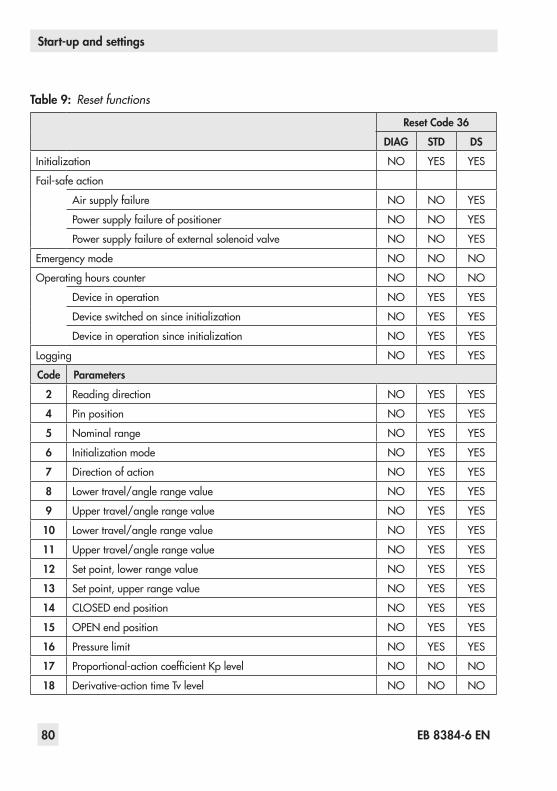
80 EB 8384-6 EN
Start-up and settings
Table 9: Reset functions
Reset Code 36
DIAG STD DS
Initialization NO YES YES
Fail-safeaction
Air supply failure NO NO YES
Power supply failure of positioner NO NO YES
Powersupplyfailureofexternalsolenoidvalve NO NO YES
Emergency mode NO NO NO
Operatinghourscounter NO NO NO
Device in operation NO YES YES
Deviceswitchedonsinceinitialization NO YES YES
Deviceinoperationsinceinitialization NO YES YES
Logging NO YES YES
Code Parameters
2 Reading direction NO YES YES
4 Pin position NO YES YES
5 Nominalrange NO YES YES
6 Initializationmode NO YES YES
7 Direction of action NO YES YES
8 Lower travel/angle range value NO YES YES
9 Uppertravel/anglerangevalue NO YES YES
10 Lower travel/angle range value NO YES YES
11 Uppertravel/anglerangevalue NO YES YES
12 Set point, lower range value NO YES YES
13 Set point, upper range value NO YES YES
14 CLOSEDendposition NO YES YES
15 OPENendposition NO YES YES
16 Pressure limit NO YES YES
17 Proportional-actioncoefficientKplevel NO NO NO
18 Derivative-actiontimeTvlevel NO NO NO
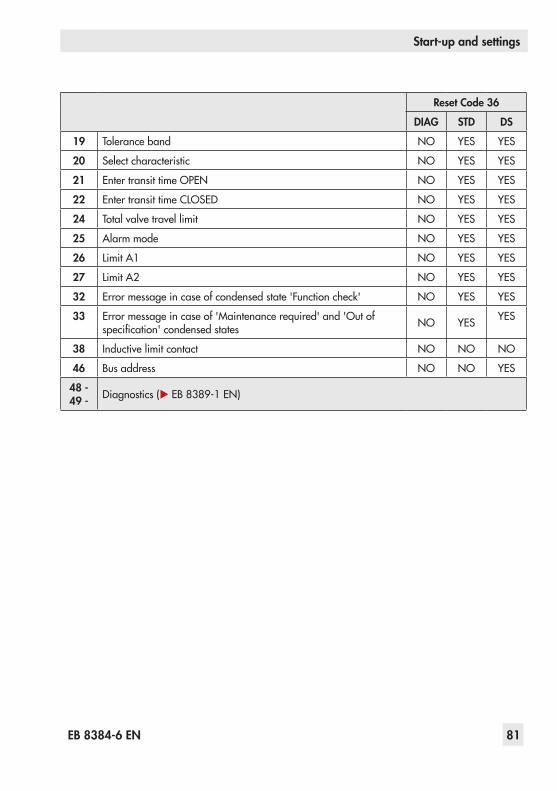
EB 8384-6 EN 81
Start-up and settings
Reset Code 36
DIAG STD DS
19 Tolerance band NO YES YES
20 Select characteristic NO YES YES
21 EntertransittimeOPEN NO YES YES
22 EntertransittimeCLOSED NO YES YES
24 Total valve travel limit NO YES YES
25 Alarm mode NO YES YES
26 Limit A1 NO YES YES
27 Limit A2 NO YES YES
32 Errormessageincaseofcondensedstate'Functioncheck' NO YES YES
33 Errormessageincaseof'Maintenancerequired'and'Outofspecification'condensedstates NO YES YES
38 Inductive limit contact NO NO NO
46 Busaddress NO NO YES
48 - 49 - Diagnostics (u EB 8389-1 EN)

82 EB 8384-6 EN
Operation
8 Operation
WARNING!Risk of injury due to the actuator stem extending or retracting.Do not touch or block the actuator stem.
8.1 Enabling and selecting pa-rameters
All codes and their meaning and default set-tingsarelistedinthecodelistinsection 14.CodeswhicharemarkedwithanasteriskmustbeenabledwithCode 3beforetheas-sociatedparameterscanbeconfiguredasdescribed below.
Code 3Configurationnotenabled
Configurationenabled
Turn g Code 3, display: NoPress , Code 3blinks.ChangethesettinginCode 3.Turn YESPress , display: Configurationisenabled.Youcannowconfigurecodesoneaftertheother:
Turn to select the required code.Press to activate the selected code. The codenumberstartstoblink.Turn to select the setting.Press toconfirmtheselectedsetting.
Note:If no settings are entered within 120 seconds, the enabled configura-tion function becomes invalid and the display returns to Code 0.
Cancel the setting:
Canceling the reading
Tocancelavaluebeforeitisconfirmed(by pressing ) proceed as follows:Turn g ESCPress .The entered value is not adopted.
8.2 Operating modes
8.2.1 Automatic and manual modes
Afterinitializationhasbeencompletedsuc-cessfully, the positioner is in automatic mode(AUTO).

EB 8384-6 EN 83
Operation
% Automatic mode
Switching to manual mode (MAN)
Turn Code 0Press , display: AUtO, Code 0blinks.Turn MANPress . The positioner changes to the man-ual mode ( ).The manual mode starts using the last set point of the automatic mode, ensuring a bumpless changeover. The current position is displayedin%.
Adjust the manual set point
% %
Turn Code 1Press , Code 1blinks.Turn untilsufficientpressurehasbeenbuilt up in the positioner and the control valve moves to the required position.
Note:The positioner automatically returns to Code 0 if no settings are made within 120 seconds, but remains in the manual mode.
Switch to automatic modeTurn Code 0Press , Code 0blinks.Turn AUTOPress . The positioner switches to automat-ic mode.
8.2.2 Fail-safe position (SAFE)Ifyouwanttomovethevalvetothefail-safepositiondeterminedduringstart-up(seesec-tion 7.1),proceedasfollows:
Turn Code 0Press , display: current operating mode (AUTO or MAN),Code 0blinks.Turn SAFEPress , display: SThevalvemovestothefail-safeposition.Ifthepositionerhasbeeninitialized,thecur-rentvalvepositionin%isindicatedonthedisplay.
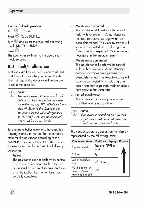
84 EB 8384-6 EN
Operation
Exit the fail-safe positionTurn Code 0Press , Code 0blinks.Turn and select the required operating mode (AUTO or MAN).Press .The positioner switches to the operating mode selected.
8.3 Fault/malfunctionAstatusclassificationisassignedtoallstatusand fault alarms in the positioner. The de-faultsettingsofthestatusclassificationarelisted in the code list.
Note:The assignment of the status classifi-cation can be changed in the opera-tor software, e.g. TROVIS-VIEW (ver-sion 4). Refer to the Operating In-structions for the valve diagnostics u EB 8389-1 EN on the enclosed CD-ROM for more details.
Toprovideabetteroverview,theclassifiedmessagesaresummarizedinacondensedstate for the positioner according to the NAMURRecommendationNE 107.Thesta-tus messages are divided into the following categories:
− FailureThe positioner cannot perform its control taskduetoafunctionalfaultintheposi-tioner itself or in one of its peripherals or aninitializationhasnotyetbeensuc-cessfully completed.
− Maintenance requiredThe positioner still performs its control task(withrestrictions).Amaintenancedemand or above average wear has been determined. The wear tolerance will soonbeexhaustedorisreducingatafasterratethanexpected.Maintenanceisnecessary in the medium term.
− Maintenance demandedThe positioner still performs its control task(withrestrictions).Amaintenancedemand or above average wear has been determined. The wear tolerance will soonbeexhaustedorisreducingatafasterratethanexpected.Maintenanceisnecessary in the short term.
− Out of specificationThe positioner is running outside the specifiedoperatingconditions.
Note:If an event is classified as “No mes-sage”, this event does not have any affect on the condensed state.
The condensed state appears on the display represented by the following icons:
Condensed state Positioner display Priority
Functioncheck Texte.g.TUNE or TEST
Failure
Outofspecifica-tion blinking
Maintenancere-quired/Mainte-nance demanded

EB 8384-6 EN 85
Operation
The message with the highest priority deter-mines the condensed state in the positioner.Iffaultalarmsexist,thepossiblesourceoferrorisdisplayedinCode49onwards.Inthis case, ERR appears on the display.
S
Example:Error caused by pin position
Refertothecodelist(section 14)forpossiblecauses and the recommended action.
Fault alarm output'Failure'asthecondensedstatecausestheoptional fault alarm output to be switched. − The'Functioncheck'condensedstatecan
also activate the fault alarm output (Code 32).
− The'Maintenancerequired/Maintenancedemanded'condensedstateand'Outofspecification'canalsoactivatethefaultalarmoutput(Code 33).
8.3.1 Confirming error mes-sages
Enable configuration:
Note:If no settings are entered within 120 seconds, the enabled configuration function becomes invalid.
Turn g Code 3, display: NoPress , Code 3blinks.
Turn YESPress , display:
Confirming error message:Turn Select the error code that you wanttoconfirm.Press .Theerrormessageisconfirmed.

86 EB 8384-6 EN
Adjusting the limit contact
9 Adjusting the limit contactThe positioner version with an inductive limit contacthasanadjustabletag(1)mountedontheaxisofrotation,whichoperatestheproximityswitch(3).For operation of the inductive limit contact, thecorrespondingswitchingamplifierac-cordingtoEN 609475-6(seesection 5.2.1)must be connected to the output circuit.Whenthetag(1)islocatedintheinductivefieldoftheswitch,theswitchassumesahighresistance.Whenitmovesoutsidethefield,the switch assumes a low resistance.Normally,thelimitcontactisadjustedsuchthatthefail-safepositionofthevalveisindi-catedwhenthecontact'sswitchingstatechanges.
Note:The inductive limit contact replaces the software limit contact A1 with ter-minal assignment +41/–42. Each switching position can optionally be set to indicate when the tag has en-tered the field, or when it has left the field.The second software limit contact re-mains effective, the function of the software limit contact A1 is disabled.
Software adaptationCode38(inductivealarmissettoYES). The inductive limit contact is connected to the ter-minals+41/–42.Thedeviceissetupac-cordingly in the delivered state.
Metaltag(1) Proximityswitch(3)Adjustmentscrew(2)
Fig. 26: Adjusting the limit contact

EB 8384-6 EN 87
Adjusting the limit contact
Adjusting the switching point:
Note:During adjustment or testing, the switching point must always be ap-proached from mid-position (50 %).
To guarantee the switching under all ambient conditions,adjusttheswitchingpointap-prox.5 %beforethemechanicalstop(OPEN–CLOSED).
For CLOSED position:1. Initializethepositioner.2. Movethevalveto5 %intheMANmode
(see display).3. Adjustthetagattheyellowadjustment
screw (2) until the tag enters or leaves thefieldandtheswitchingamplifierre-sponds.Youcanmeasuretheswitchingvoltageas an indicator.
Contact function: − Tagleavingthefield>Proximityswitch
assumes low resistance − Tagenteringthefield>Proximityswitch
assumes high resistance
For OPEN position:1. Initializethepositioner.2. Movethevalveto95 %intheMAN
mode (see display).3. Adjustthetag(1)attheyellowadjust-
ment screw (2) until the tag enters or leavesthefieldoftheproximityswitch(3).
Youcanmeasuretheswitchingvoltageas an indicator.
Contact function: − Tagleavingthefield>Proximityswitch
assumes low resistance − Tagenteringthefield>Proximityswitch
assumes high resistance
9.1 Retrofitting an inductive limit contact
Required retrofit kit:Limit contact Orderno.1400-7460
Note:The same requirements apply to ret-rofitting an inductive limit contact as to servicing the positioner. For explo-sion-protected positioners, the re-quirements in section 11 (Servicing explosion-protected devices) need to be kept. Check the "Limit switch, in-ductive" box on the nameplate after installing the limit comtact.
1. Takeofftherotarypushbutton(3)andcap(1),unthreadthefivefasteningscrews(2)andliftofftheplasticcover(9)togetherwith the display, taking care not to dam-age the ribbon cable (between PCB and display).
2. Useaknifetocutanopeningatthemarkedlocation(4).
3. Push the connector (11) with cable throughtheopeningandsecuretheprox-

88 EB 8384-6 EN
Adjusting the limit contact
imityswitch(7)onthecoverwithadotofglue.
4. Removethejumper(8801-2267)atthesocketX7ofthetopboardandinsertthecable connector (11).
5. Guidethecableinsuchamannerthattheplasticcovercanbeplacedbackontothepositioner.Insertthefixingscrews(2)andscrewtight.Attachtheclampingplate(8)ontotheproximityswitch.
6. Attachtherotaryswitch(5).Makesuretheflattenedsideofthepositionershaftisturned so that the rotary switch (5) can be attachedwiththemetaltagnexttotheproximityswitch.
7. Onstart-upofthepositioner,settheop-tioninductivealarmunderCode 38fromNo to YES.
1
2
3
4
5
8
6
7
9 7
SocketX7(11)
1 Cap 6 Metaltag2 Screw 7 Proximityswitch3 Rotary pushbutton 8 Clamping plate4 Marking 9 Plastic cover5 Rotary switch 11 Connector
Fig. 27: Retrofitting an inductive limit contact
EB 8384-6 EN 89
Maintenance
10 MaintenanceThe positioner does not require any mainte-nance.Therearefilterswitha100 µmmeshsizeinthe pneumatic connections for supply and output which can be removed and cleaned, if required.The maintenance instructions of any up-stream supply air pressure reducing stations must be observed.
11 Servicing explosion-protected devices
Ifapartofthedeviceonwhichtheexplosionprotection is based needs to be serviced, the devicemustnotbeputbackintooperationuntilaqualifiedinspectorhasassesseditac-cordingtoexplosionprotectionrequire-ments,hasissuedaninspectioncertificateorgiventhedeviceamarkofconformity.In-spectionbyaqualifiedinspectorisnotre-quired if the manufacturer performs a rou-tinetestonthedevicebeforeputtingitbackinto operation. Document the passing of the routinetestbyattachingamarkofconformi-tytothedevice.Replaceexplosion-protectedcomponentsonlywithoriginal,routine-testedcomponents from the manufacturer.Devices that have already been operated outside hazardous areas and are intended for future use inside hazardous areas must comply with the safety requirements placed on serviced devices. Before being operated
inside hazardous areas, test the devices ac-cording to the specifications for servicing explosion-protected devices.Readsection 13formaintenance,calibrationandadjustmentworkinsideandoutsidehazardousareas.
12 Firmware update (serial in-terface)
Firmware updates on positioners currently in operation can be performed as follows:WhenupdatesareperformedbyaserviceemployeeappointedbySAMSON,theup-dateisconfirmedonthedevicebythetestmarkassignedbySAMSON’sQualityAssur-ance.In all other cases, only plant operator per-sonnel with written approval may perform updates.Updatesaretobeconfirmedbyap-proved personnel on the device.Laptops and PCs connected to the power supply must not be used without an addition-al protective circuit.This does not apply to laptops in battery op-eration. In this case, it is assumed that a bat-tery-poweredlaptoprunsbrieflyforsoftwareprogramming or testing purposes.
a) Updates outside the hazardous area:Remove the positioners from the plant.Updatethemoutsidethehaz-ardous area.
90 EB 8384-6 EN
Maintenance, calibration and work on equipment
b) Updates on site:
Updatesonsiteareonlypermittedafter the plant operator presented a signedhotworkpermit.
After updating has been completed, add the currentfirmwaretothenameplate;thiscanbe done using labels.
13 Maintenance, calibration and work on equipment
Interconnection with intrinsically safe cir-cuits to check or calibrate the equipment in-side or outside hazardous areas is to be performed only with intrinsically safe cur-rent/voltage calibrators and measuring in-struments to rule out any damage to com-ponents relevant to explosion protection.Observe the maximum permissible values specified in the certificates for intrinsically safe circuits.
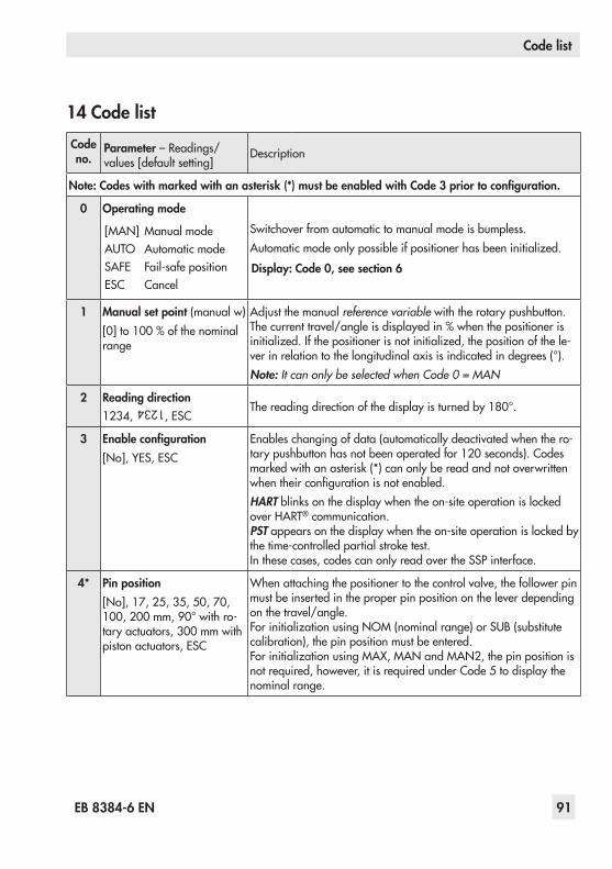
EB 8384-6 EN 91
Code list
14 Code listCode no.
Parameter–Readings/values[defaultsetting]
Description
Note: Codes with marked with an asterisk (*) must be enabled with Code 3 prior to configuration.
0 Operating mode
[MAN] ManualmodeAUTO Automatic modeSAFE Fail-safepositionESC Cancel
Switchover from automatic to manual mode is bumpless.Automaticmodeonlypossibleifpositionerhasbeeninitialized.
Display: Code 0, see section 6
1 Manual set point (manual w)[0]to100 %ofthenominalrange
Adjustthemanualreference variable with the rotary pushbutton. Thecurrenttravel/angleisdisplayedin%whenthepositionerisinitialized.Ifthepositionerisnotinitialized,thepositionofthele-verinrelationtothelongitudinalaxisisindicatedindegrees(°).Note: It can only be selected when Code 0 = MAN
2 Reading direction1234,
1234
, ESCThereadingdirectionofthedisplayisturnedby180°.
3 Enable configuration[No],YES,ESC
Enables changing of data (automatically deactivated when the ro-tarypushbuttonhasnotbeenoperatedfor120 seconds).Codesmarkedwithanasterisk(*)canonlybereadandnotoverwrittenwhentheirconfigurationisnotenabled.HARTblinksonthedisplaywhentheon-siteoperationislockedover HART® communication.PSTappearsonthedisplaywhentheon-siteoperationislockedbythetime-controlledpartialstroketest.In these cases, codes can only read over the SSP interface.
4* Pin position[No],17,25,35,50,70,100,200 mm,90°withro-taryactuators,300 mmwithpiston actuators, ESC
Whenattachingthepositionertothecontrolvalve,thefollowerpinmust be inserted in the proper pin position on the lever depending on the travel/angle.ForinitializationusingNOM(nominalrange)orSUB(substitutecalibration), the pin position must be entered.ForinitializationusingMAX,MANandMAN2,thepinpositionisnotrequired,however,itisrequiredunderCode 5todisplaythenominal range.

92 EB 8384-6 EN
Code list
Code no.
Parameter–Readings/values[defaultsetting]
Description
4* Pin position(continued)If you select a pin position in Code 4 that is too small, the positioner switches to SAFE mode for reasons of safety.
Pin position Standard AdjustmentrangeCode 4 Code 5 Code 517 7.5 3.6 to 17.725 7.5 5.0 to 25.035 15.0 7.0 to 35.450 30.0 10.0 to 50.070 40.0 14.0 to 70.7100 60.0 20.0 to 100.0200 120.0 40.0 to 200.090° 90.0 24.0 to 100.0
5* Nominal range[15.0]mmorangle°,ESC
ForinitializationusingNOM(nominalrange)orSUB(substitutecalibration), the nominal range must be entered. The possible ad-justmentrangedependsonthepinpositionfromthetableforCode 4.Afterinitializationtothemaximumrange(MAX),themaximumnominaltravel/anglereachedoninitializationisdisplayed.
6* Initialization mode (init mode)[MAX],NOM,MAN,MAN2,SUB,KP,ZP,ESC
MAX: Maximumrange·Forsimplestart-upofvalveswithtwoclearlydefinedmechanicalendpositions·Thepositionerdetermines travel/angle of rotation of the closing member fromtheCLOSEDpositiontotheoppositestopintheactu-ator
NOM: Nominalrange·Forallglobevalves·Thepositionerde-termines travel/angle of rotation of the closing member fromtheCLOSEDpositiontothespecifiednominalrange
MAN: Manualsetting1·Forallglobevalveswithunknownnominalrange(OPENposition)·Thepositionerdeter-mines travel/angle of rotation from the manually selected OPENposition(100 %)totheCLOSEDposition
MAN2: Manualsetting2·Forallglobevalveswithunknownnominalrange(OPENandCLOSEDposition)·Theposi-tioner determines travel/angle of rotation between the manuallyselectedOPEN(100 %)andthemanuallyse-lectedCLOSEDposition(0 %)
SUB: Substitutecalibration·Toreplaceapositionerwhiletheplant is running, with the least amount of disruption to the plant

EB 8384-6 EN 93
Code list
Code no.
Parameter–Readings/values[defaultsetting]
Description
6* Initialization mode (init mode)(continued)
KP: Finetuningoftheinputfilter·Thevalvemovesthroughitsentire valve range.
NP: Zerocalibration·Thezeropointisrecalibrated.NOTICE Valve will temporarily be moved from its operat-ing point to CLOSED position.
7* Direction of action (w/x)[ää],äæ, ESC
Direction of action of the set point in relation to the valve positionää: Increasing/increasing: a globe valve opens as the set
point increases.äæ: Increasing/decreasing: a globe valve closes as the set
point increases.
The direction of action is adapted to the change in closed direction as follows:ATO: AIRTOOPEN·Oncompletinginitialization,thedirection
of action remains increasing/ increasing (ää). A globe valve opens as the reference variable increases.
ATC: AIRTOCLOSE·Oncompletinginitialization,thedirec-tion of action changes to increasing/decreasing (äæ). A globe valve closes as the reference signal increases.
8* Lower travel/angle range value (lowerx-rangevalue)[0.0]to80.0 %ofthenomi-nal range, ESCSpecified in mm or angle ° provided Code 4 is activat-ed.
Lower range value for the travel/angle of rotation in the operating range.Nominalrangeandcharacteristicareautomaticallyadapted.The operating range is the actual travel/angle of the valve and is limitedbythelowertravel/anglerangevalue(Code 8)andtheuppertravel/anglerangevalue(Code 9).Usually,theoperatingrangeandthenominalrangeareidentical.The nominal range can be limited to the operating range by the lower and upper travel/angle range values. The value is displayed or must be entered.SeealsotheexampleinCode 9.
9* Upper travel/angle range value (upperx-rangevalue)20.0to[100.0 %]ofthenominal range, ESCSpecified in mm or angle ° provided Code 4 is activat-ed.
Upperrangevalueforthetravel/angleofrotationintheoperatingrange.Nominalrangeandcharacteristicareautomaticallyadapted.Example: Theoperatingrangeismodified,forexample,tolimittherangeofacontrolvalvewhichhasbeensizedtoolarge.Forthis function, the entire resolution range of the set point is convert-ed to the new limits.0%onthedisplaycorrespondstotheadjustedlowerlimitand100%totheadjustedupperlimit.
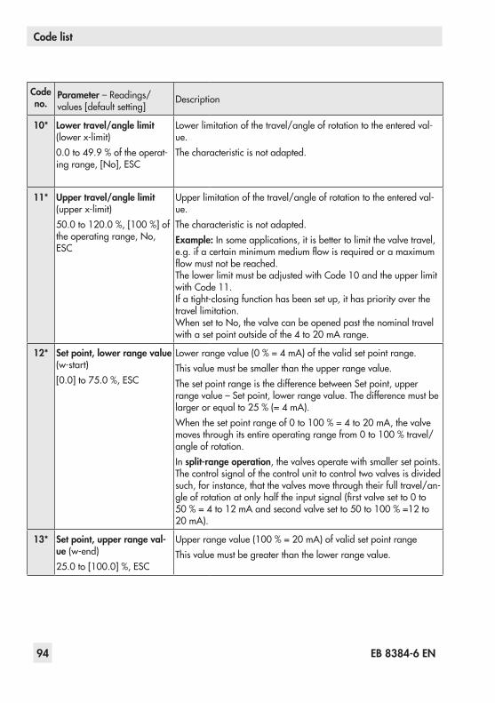
94 EB 8384-6 EN
Code list
Code no.
Parameter–Readings/values[defaultsetting]
Description
10* Lower travel/angle limit (lowerx-limit)0.0to49.9 %oftheoperat-ingrange,[No],ESC
Lower limitation of the travel/angle of rotation to the entered val-ue.The characteristic is not adapted.
11* Upper travel/angle limit (upperx-limit)50.0to120.0 %,[100 %]oftheoperatingrange,No,ESC
Upperlimitationofthetravel/angleofrotationtotheenteredval-ue.The characteristic is not adapted.Example: In some applications, it is better to limit the valve travel, e.g.ifacertainminimummediumflowisrequiredoramaximumflowmustnotbereached.ThelowerlimitmustbeadjustedwithCode 10andtheupperlimitwithCode 11.Ifatight-closingfunctionhasbeensetup,ithaspriorityoverthetravel limitation.WhensettoNo,thevalvecanbeopenedpastthenominaltravelwithasetpointoutsideofthe4to20 mArange.
12* Set point, lower range value (w-start)[0.0]to75.0 %,ESC
Lowerrangevalue(0 %=4 mA)ofthevalidsetpointrange.This value must be smaller than the upper range value.The set point range is the difference between Set point, upper rangevalue–Setpoint,lowerrangevalue.Thedifferencemustbelargerorequalto25 %(=4 mA).Whenthesetpointrangeof0to100 %=4to20 mA,thevalvemovesthroughitsentireoperatingrangefrom0to100 %travel/angle of rotation.In split-range operation, the valves operate with smaller set points. The control signal of the control unit to control two valves is divided such, for instance, that the valves move through their full travel/an-gleofrotationatonlyhalftheinputsignal(firstvalvesetto0to50 %=4to12 mAandsecondvalvesetto50to100 %=12to20 mA).
13* Set point, upper range val-ue (w-end)25.0to[100.0]%,ESC
Upperrangevalue(100 %=20 mA)ofvalidsetpointrangeThis value must be greater than the lower range value.
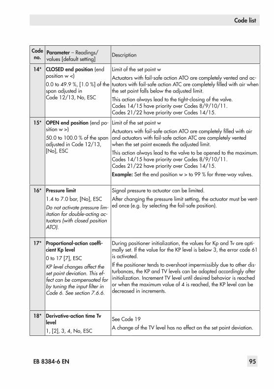
EB 8384-6 EN 95
Code list
Code no.
Parameter–Readings/values[defaultsetting]
Description
14* CLOSED end position (end position w <)0.0to49.9 %,[1.0 %]ofthespanadjustedinCode 12/13,No,ESC
Limit of the set point wActuatorswithfail-safeactionATOarecompletelyventedandac-tuatorswithfail-safeactionATCarecompletelyfilledwithairwhenthesetpointfallsbelowtheadjustedlimit.Thisactionalwaysleadtothetight-closingofthevalve.Codes14/15havepriorityoverCodes8/9/10/11.Codes 21/22 have priority over Codes 14/15.
15* OPEN end position (end po-sition w >)50.0to100.0 %ofthespanadjustedinCode 12/13,[No],ESC
Limit of the set point wActuatorswithfail-safeactionATOarecompletelyfilledwithairandactuatorswithfail-safeactionATCarecompletelyventedwhenthesetpointexceedstheadjustedlimit.Thisactionalwaysleadtothevalvetobeopenedtothemaximum.Codes14/15havepriorityoverCodes8/9/10/11.Codes 21/22 have priority over Codes 14/15.Example:Settheendpositionw>to99 %forthree-wayvalves.
16* Pressure limit1.4to7.0bar,[No],ESCDo not activate pressure lim-itation for double-acting ac-tuators (with closed position ATO).
Signal pressure to actuator can be limited.After changing the pressure limit setting, the actuator must be vent-edonce(e.g.byselectingthefail-safeposition).
17* Proportional-action coeffi-cient Kp level0to17[7],ESCKP level changes affect the set point deviation. This ef-fect can be compensated for by tuning the input filter in Code 6. See section 7.6.6.
Duringpositionerinitialization,thevaluesforKpandTvareopti-mallyset.IfthevaluefortheKPlevelisbelow3,theerrorcode61is activated.If the positioner tends to overshoot impermissibly due to other dis-turbances,theKPandTVlevelscanbeadaptedaccordinglyafterinitialization.IncrementTVleveluntildesiredbehaviorisreachedorwhenthemaximumvalueof4isreached,theKPlevelcanbedecreased in increments.
18* Derivative-action time Tv level1,[2],3,4,No,ESC
SeeCode 19A change of the TV level has no effect on the set point deviation.
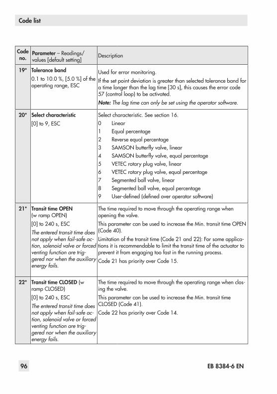
96 EB 8384-6 EN
Code list
Code no.
Parameter–Readings/values[defaultsetting]
Description
19* Tolerance band0.1to10.0 %,[5.0 %]oftheoperating range, ESC
Usedforerrormonitoring.If the set point deviation is greater than selected tolerance band for atimelongerthanthelagtime[30 s],thiscausestheerrorcode57(controlloop)tobeactivated.Note: The lag time can only be set using the operator software.
20* Select characteristic[0]to9,ESC
Selectcharacteristic.Seesection 16.0 Linear1 Equal percentage2 Reverse equal percentage3 SAMSONbutterflyvalve,linear4 SAMSONbutterflyvalve,equalpercentage5 VETEC rotary plug valve, linear6 VETEC rotary plug valve, equal percentage7 Segmented ball valve, linear8 Segmented ball valve, equal percentage9 User-defined(definedoveroperatorsoftware)
21* Transit time OPEN (wrampOPEN)[0]to240 s,ESCThe entered transit time does not apply when fail-safe ac-tion, solenoid valve or forced venting function are trig-gered nor when the auxiliary energy fails.
The time required to move through the operating range when opening the valve.ThisparametercanbeusedtoincreasetheMin.transittimeOPEN(Code 40).Limitationofthetransittime(Code 21and 22):Forsomeapplica-tions it is recommendable to limit the transit time of the actuator to prevent it from engaging too fast in the running process.Code 21haspriorityoverCode 15.
22* Transit time CLOSED (w rampCLOSED)[0]to240s,ESCThe entered transit time does not apply when fail-safe ac-tion, solenoid valve or forced venting function are trig-gered nor when the auxiliary energy fails.
The time required to move through the operating range when clos-ing the valve.ThisparametercanbeusedtoincreasetheMin.transittimeCLOSED(Code 41).Code 22haspriorityoverCode 14.
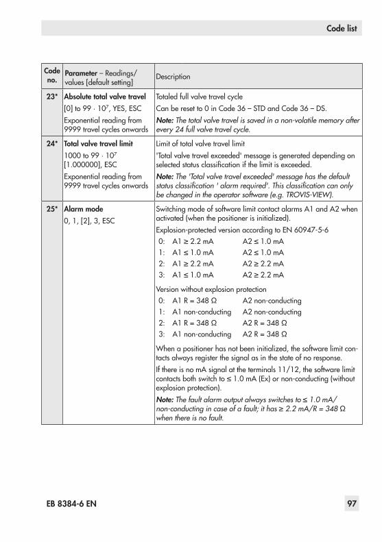
EB 8384-6 EN 97
Code list
Code no.
Parameter–Readings/values[defaultsetting]
Description
23* Absolute total valve travel[0]to99·107,YES,ESCExponentialreadingfrom9999travelcyclesonwards
Totaled full valve travel cycleCanberesetto0inCode 36–STDandCode 36–DS.Note: The total valve travel is saved in a non-volatile memory after every 24 full valve travel cycle.
24* Total valve travel limit1000to99·107 [1.000000],ESCExponentialreadingfrom9999travelcyclesonwards
Limit of total valve travel limit'Totalvalvetravelexceeded'messageisgenerateddependingonselectedstatusclassificationifthelimitisexceeded.Note: The 'Total valve travel exceeded' message has the default status classification ' alarm required'. This classification can only be changed in the operator software (e.g. TROVIS-VIEW).
25* Alarm mode0,1,[2],3,ESC
Switching mode of software limit contact alarms A1 and A2 when activated(whenthepositionerisinitialized).Explosion-protectedversionaccordingtoEN 60947-5-60: A1≥2.2 mA A2≤1.0 mA1: A1≤1.0 mA A2≤1.0 mA2: A1≥2.2 mA A2≥2.2 mA3: A1≤1.0 mA A2≥2.2 mA
Versionwithoutexplosionprotection0: A1R=348 Ω A2non-conducting1: A1non-conducting A2non-conducting2: A1R=348 Ω A2R=348 Ω3: A1non-conducting A2R=348 Ω
Whenapositionerhasnotbeeninitialized,thesoftwarelimitcon-tacts always register the signal as in the state of no response.If there is no mA signal at the terminals 11/12, the software limit contactsbothswitchto≤1.0 mA(Ex)ornon-conducting(withoutexplosionprotection).Note: The fault alarm output always switches to ≤ 1.0 mA/non-conducting in case of a fault; it has ≥ 2.2 mA/R = 348 Ω when there is no fault.

98 EB 8384-6 EN
Code list
Code no.
Parameter–Readings/values[defaultsetting]
Description
26* Limit A1 (alarm limit 1)0.0to100.0[2.0]%oftheoperatingrange,No,ESCThe setting has no effect when an inductive limit con-tact is installed.
The valve position limit relating to the operating range.Alarm A1 responds when the value falls below the limit.
27* Limit A2 (alarm limit 2)0.0to100.0[98.0]%oftheoperatingrange,No,ESC
The valve position limit relating to the operating range.Alarm A2 responds when the value falls below the limit.
28* Alarm test
Reading direction:Standard Turned[No] [No]A1 1AA2 2AA3 3AESC ESC
Testing the software limit contact alarm A1 and A2 as well as the fault alarm contact A3.Ifthetestisactivated,thecontactisswitchedfivetimes.A1/1A:SoftwarelimitcontactA1to≥2.2 mAA2/2A:SoftwarelimitcontactA2to≥2.2 mAA3/3A:FaultalarmcontactA3to≤1.0 mA
29* Position transmitter x/ix 3)
[ää],äæ, ESCOperatingdirectionofthepositiontransmitter.Thisindicateshowthe travel/angle position is assigned to the output signal i, based ontheclosedposition.Theoperatingrange(seeCode 8)ofthevalveisrepresentedbythe4to20 mAsignal.Valuesexceedingorfallingbelowthelimits2.4to21.6mAcanberepresented.Whena positioner has not been connected (set point less than 3.6 mA), thesignalis0.9 mAand3.8 mAor4.4mAwhenthepositionerhasnotbeeninitialized.WhenCode 32=YES,thepositiontransmitterissuesthevalueassetinCode 30duringinitializationorzerocalibration.WhenCode 32=No,4 mAisissuedduringarunningautotune.
30* Fault alarm ix 3)
[No],HI,LO,ESCSelect if and how faults that cause the fault alarm contact to be switched are also indicated at the position transmitter output.HIix=21.6±0.1 mAorLOix=2.4±0.1 mA

EB 8384-6 EN 99
Code list
Code no.
Parameter–Readings/values[defaultsetting]
Description
31* Position transmitter test 3)
–10.0to110.0 %oftheop-eratingrange·ESC,[defaultvalue is last indicated value ofthepositiontransmitter]
Testing the position transmitter. Values can be entered in relation to the operating range.Themomentaryvalvepositionisusedininitializedpositionerslo-callyasthestartvalue(bumplesschangeovertothetestmode).Ontesting over software, the entered simulation value is issued as the positionfeedbacksignalfor30seconds.
3)Analogpositiontransmitter:Code 29/30/31canonlybeselectedifthepositiontransmitter(optional)isinstalled.
32* Error message in case of 'Function check' condensed state[YES],No,ESC
YES: 'Failure'and'Functioncheck'condensedstatecauseanerror message to be generated.
No: 'Failure'condensedstatecausesanerrormessagetobegenerated.
33* Error message in case of 'Maintenance required' and 'Out of specification' con-densed states[YES],No,ESC
YES: 'Failure','Maintenancerequired'and'Outofspecifica-tion'condensedstatecauseanerrormessagetobegen-erated.
No: 'Failure'condensedstatecausesanerrormessagetobegenerated.
34* Closing directionCL,[CCL],ESC
CL: ClockwiseCCL: Counterclockwise
Directionofrotationtoreachthevalve'sCLOSEDposition(viewonto rotary switch with positioner cover open).Note: Needs only be entered in initialization mode SUB (Code 6).
35* Blocking position[0.0]mm/°/%,ESC
DistancetoCLOSEDpositionNote: Needs only be entered in initialization mode SUB (Code 6).
36* ResetSTD,DIAG,DS,ESC
STD: Resetsstart-up − Resets parameters to their default settings. − Resets diagnostics assessment. − Information parameters (read only) remain unchanged. − Re-initializepositioner.
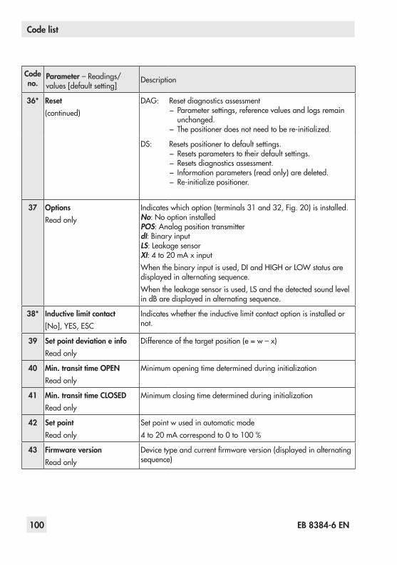
100 EB 8384-6 EN
Code list
Code no.
Parameter–Readings/values[defaultsetting]
Description
36* Reset(continued)
DAG: Reset diagnostics assessment − Parameter settings, reference values and logs remain unchanged.
− Thepositionerdoesnotneedtobere-initialized.
DS: Resets positioner to default settings. − Resets parameters to their default settings. − Resets diagnostics assessment. − Information parameters (read only) are deleted. − Re-initializepositioner.
37 OptionsRead only
Indicateswhichoption(terminals31and32,Fig. 20)isinstalled.No:NooptioninstalledPOS: Analog position transmitterdI:BinaryinputLS:LeakagesensorXI:4to20 mAxinputWhenthebinaryinputisused,DIandHIGHorLOWstatusaredisplayed in alternating sequence.Whentheleakagesensorisused,LSandthedetectedsoundlevelindBaredisplayedinalternatingsequence.
38* Inductive limit contact[No],YES,ESC
Indicates whether the inductive limit contact option is installed or not.
39 Set point deviation e infoRead only
Differenceofthetargetposition(e=w–x)
40 Min. transit time OPENRead only
Minimumopeningtimedeterminedduringinitialization
41 Min. transit time CLOSEDRead only
Minimumclosingtimedeterminedduringinitialization
42 Set pointRead only
Set point w used in automatic mode4to20 mAcorrespondto0to100 %
43 Firmware versionRead only
Devicetypeandcurrentfirmwareversion(displayedinalternatingsequence)

EB 8384-6 EN 101
Code list
Code no.
Parameter–Readings/values[defaultsetting]
Description
44 y infoRead only
Controlsignalyin%inrelationtothetravelrangedeterminedduringinitializationMAX: Thepositionerbuildsupitsmaximumoutputpressure,see
descriptioninCode 14and15.0P: The positioner vents completely, see description in Code
14 and 15.–––: Thepositionerisnotinitialized.
45 Internal solenoid valve/forced ventingRead only
Indicates whether a solenoid valve/forced venting is installed or not.Ifavoltagesupplyisconnectedattheterminals+81/–82,YES and HIGH appear on the display in alternating sequence. If a volt-agesupplyisnotconnected(actuatorvented,fail-safepositionin-dicated on the display by the S icon), YES and LOW appear on the display in alternating sequence.
46* Bus address[0]to15,ESC
UsingtheHART®protocol,allconnectedcontrolroomandfieldunitscanbeaddressedindividuallyusingapoint-to-pointconnec-tion or the standard (multidrop) bus.Point-to-point connection: HART® master device connected to one HART®fieldunit.Withthisconnection,thedeviceaddressmustal-sobesetto'0'.Standard (multidrop) bus:Upto15fieldunitsconnectedinparal-lel to a single pair of wires. The master device distinguishes them by their preset addresses between 1 and 15.
47* HART® write protectionYES,[No],ESC
Whenwriteprotectionisactive,devicedatacanberead,butnotoverwritten over HART® communication.
48*49*
Diagnostic parameters · DetailsonEXPERTplusValveDiagnosticsintheOperatingInstructionsu EB 8389-1 EN.
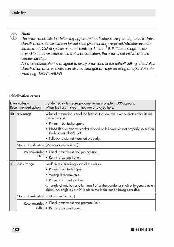
102 EB 8384-6 EN
Code list
Note:The error codes listed in following appear in the display corresponding to their status classification set over the condensed state (Maintenance required/Maintenance de-manded: , Out of specification: blinking, Failure: ). If “No message” is as-signed to the error code as the status classification, the error is not included in the condensed state.A status classification is assigned to every error code in the default setting. The status classification of error codes can also be changed as required using an operator soft-ware (e.g. TROVIS-VIEW).
Initialization errors
Error codes – Recommended action
Condensed state message active, when prompted, ERR appears.Whenfaultalarmsexist,theyaredisplayedhere.
50 x > range Valueofmeasuringsignaltoohighortoolow;theleveroperatesnearitsme-chanical stops.• Pin not mounted properly• NAMURattachment:bracketslippedorfollowerpinnotproperlyseatedonthefollowerplate'sslot.
• Follower plate not mounted properly.
Statusclassification [Maintenancerequired]
Recommended action
• Checkattachmentandpinposition.• Re-initializepositioner.
51 Δx < range Insufficientmeasuringspanofthesensor• Pin not mounted properly.•Wronglevermounted.• Pressure limit set too low.Anangleofrotationsmallerthan16°atthepositionershaftonlygeneratesanalarm.Ananglebelow9°leadstotheinitializationbeingcanceled.
Statusclassification [Outofspecification]
Recommended action
• Checkattachmentandpressurelimit.• Re-initializepositioner.
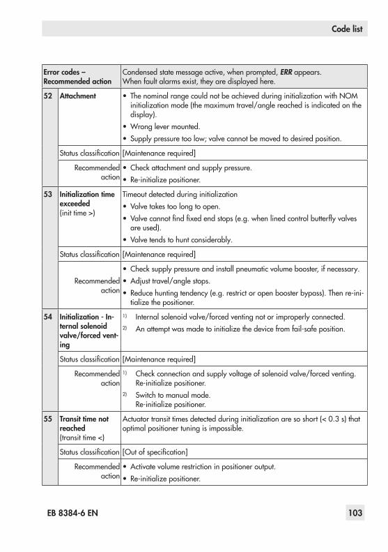
EB 8384-6 EN 103
Code list
Error codes – Recommended action
Condensed state message active, when prompted, ERR appears.Whenfaultalarmsexist,theyaredisplayedhere.
52 Attachment • ThenominalrangecouldnotbeachievedduringinitializationwithNOMinitializationmode(themaximumtravel/anglereachedisindicatedonthedisplay).
•Wronglevermounted.• Supplypressuretoolow;valvecannotbemovedtodesiredposition.
Statusclassification [Maintenancerequired]
Recommended action
• Checkattachmentandsupplypressure.• Re-initializepositioner.
53 Initialization time exceeded (init time >)
Timeoutdetectedduringinitialization• Valvetakestoolongtoopen.• Valvecannotfindfixedendstops(e.g.whenlinedcontrolbutterflyvalves
are used).• Valve tends to hunt considerably.
Statusclassification [Maintenancerequired]
Recommended action
• Checksupplypressureandinstallpneumaticvolumebooster,ifnecessary.• Adjusttravel/anglestops.• Reducehuntingtendency(e.g.restrictoropenboosterbypass).Thenre-ini-tializethepositioner.
54 Initialization - In-ternal solenoid valve/forced vent-ing
1) Internal solenoid valve/forced venting not or improperly connected.2) Anattemptwasmadetoinitializethedevicefromfail-safeposition.
Statusclassification [Maintenancerequired]
Recommended action
1) Checkconnectionandsupplyvoltageofsolenoidvalve/forcedventing. Re-initializepositioner.
2) Switch to manual mode. Re-initializepositioner.
55 Transit time not reached (transit time <)
Actuatortransittimesdetectedduringinitializationaresoshort(< 0.3 s)thatoptimal positioner tuning is impossible.
Statusclassification [Outofspecification]
Recommended action
•Activate volume restriction in positioner output.• Re-initializepositioner.

104 EB 8384-6 EN
Code list
Error codes – Recommended action
Condensed state message active, when prompted, ERR appears.Whenfaultalarmsexist,theyaredisplayedhere.
56 Pin/switch position
1) Pinpositionnotenteredfornominalrange(NOM)orsubstitute(SUB)ini-tialization.
2) ATO/ATCswitchdefective.
Statusclassification [Maintenancerequired]
Recommended action
1) Enter pin position and nominal range. Re-initializepositioner.
2) ReturnpositionertoSAMSONforrepair.
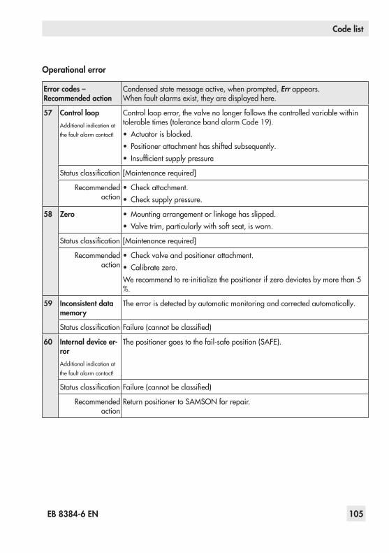
EB 8384-6 EN 105
Code list
Operational error
Error codes – Recommended action
Condensed state message active, when prompted, Err appears.Whenfaultalarmsexist,theyaredisplayedhere.
57 Control loopAdditional indication at thefaultalarmcontact!
Control loop error, the valve no longer follows the controlled variable within tolerabletimes(tolerancebandalarmCode19).• Actuatorisblocked.• Positioner attachment has shifted subsequently.• Insufficientsupplypressure
Statusclassification [Maintenancerequired]
Recommended action
• Checkattachment.• Checksupplypressure.
58 Zero • Mountingarrangementorlinkagehasslipped.• Valve trim, particularly with soft seat, is worn.
Statusclassification [Maintenancerequired]
Recommended action
• Checkvalveandpositionerattachment.• Calibratezero.Werecommendtore-initializethepositionerifzerodeviatesbymorethan5%.
59 Inconsistent data memory
The error is detected by automatic monitoring and corrected automatically.
Statusclassification Failure(cannotbeclassified)
60 Internal device er-rorAdditional indication at thefaultalarmcontact!
Thepositionergoestothefail-safeposition(SAFE).
Statusclassification Failure(cannotbeclassified)
Recommended action
ReturnpositionertoSAMSONforrepair.

106 EB 8384-6 EN
Code list
Error codes – Recommended action
Condensed state message active, when prompted, Err appears.Whenfaultalarmsexist,theyaredisplayedhere.
61 KP too low Proportional-actioncoefficientKplevellowerthan3wasdetectedduringini-tialization.Note: A Kp level < 3 does not cause the initialization process to be canceled.
Statusclassification [Maintenancerequired]
Recommended action
•Activate volume restriction in positioner output.• Increase the bypass restriction setting of booster (if installed).
Hardware error
Error codes – Recommended action
Condensed state message active, when prompted, Err appears.Whenfaultalarmsexist,theyaredisplayedhere.
62 x signalAdditional indication at thefaultalarmcontact!
• Actuator'smeasuredvaluerecordingfailed.•Conductive plastic element defective.Theemergencymodeonthedisplayisindicatedbyablinkingclosed-loopop-eration icon and 4 dashes instead of the position reading.Note on the closed-loop operation: If the measuring system has failed, the positioner is still in a reliable state. The positioner switches to emergency mode where the position cannot be accurately controlled anymore. However, the positioner continues operation according to its set point so that the process remains in a safe state.
Statusclassification [Maintenancedemanded]
Recommended action
ReturnpositionertoSAMSONforrepair.
63 SIL shutdown/w too low
1) Emergencyshutdownofthei/pblockisimplementedby3.8 mAor4.4 mA(dependingonthepositionerversion)´.
2) Thesetpointwislowerthan3.7 mA.Thisstateisindicatedontheposi-tionerdisplaybyLOWblinking.
Statusclassification [Nomessage]
Recommended action
1) Raise the current (depending on version) above the limit.2) Checksetpointw.Ifnecessary,restrictlowerlimitofcurrentsourcetoen-
surethatacurrentbelow3.7 mAcannotbeissued.

EB 8384-6 EN 107
Code list
Error codes – Recommended action
Condensed state message active, when prompted, Err appears.Whenfaultalarmsexist,theyaredisplayedhere.
64 i/p converter (y) Current circuit of i/p converter interrupted.
Statusclassification Failure(cannotbeclassified)
Recommended action
ReturnpositionertoSAMSONforrepair.

108 EB 8384-6 EN
Code list
Error appendix
Error codes – Recommended action
Condensed state message active, when prompted, Err appears.Whenfaultalarmsexist,theyaredisplayedhere.
65 HardwareAdditional indication at the faultalarmcontact!
• Initializationkeyjammed.• Ahardwareerrorhasoccurred.Thepositionerchangestothefail-
safe position (SAFE).Aslongastheerrorexists,noEXPERTplusdiagnosticmessagesarelogged.
Statusclassification [Failure]
Recommended action Confirmerrorandreturntoautomaticmode,orperformaresetandre-initializethepositioner.Ifthisisnotsuccessful,returnpositionertoSAMSONAGforrepair.
66 Unassigned
67 Check calculationAdditional indication at the faultalarmcontact!
Hardware controller monitored by test calculation.
Statusclassification [Failure]
Recommended action Confirmerror.Ifthisisnotpossible,returnpositionertoSAMSONAGfor repair.
Data error
Error codes – Recommended action
Condensed state message active, when prompted, Err appears.Whenfaultalarmsexist,theyaredisplayedhere.
68 to 75
Unassigned
76 No emergency mode Thetravelmeasuringsystemofthepositionerhasaself-monitoringfunc-tion(seeCode 62).Anemergencymode(open-loopcontrol)isnotavailableforcertainac-tuators,suchasdouble-actingactuators.Inthiscase,thepositionerchangestothefail-safeposition(SAFE)whenameasuringerroroccurs.Duringtheinitialization,thepositionerautomaticallycheckswhethertheactuator has such a function or not.
Statusclassification [Nomessage]
Recommended action Merelyinformation,confirm,ifnecessary.Nofurtheractionrequired.

EB 8384-6 EN 109
Code list
Diagnosis errors
Error codes – Recommended action
Condensed state message active, when prompted, Err appears.Whenfaultalarmsexist,theyaredisplayedhere.
77 Unassigned
78 Unassigned
79 Collective error MessagesgeneratedinEXPERTplusTheerrordoesnothaveanydirecteffectonthepositioner'sfunctioning.
Statusclassification Maintenancerequired(cannotbeclassified)
80 Unassigned
81 Valve signature can-celed
Error during automatic plotting of the valve signatureErrormessagesarenotyetsavedinanon-volatilememory.Theycannotbe reset.
Statusclassification [Maintenancerequired]
Recommended action Restartthevalvesignaturerecordingorstartinitializationincludingvalvesignature.
82 Unassigned
83 Unassigned
84 PST/FST Apartialstroketestorfullstroketestcannotbestartedorhasbeencan-celed.
Statusclassification [Nomessage]
Recommended action Read out test status (only in the operator software)
85 On/off valve Thetransittimeandbreakawaytimeorthefinaltravel/anglevalueofthe on/off valve has changed.
Statusclassification [Nomessage]
Recommended action Checkvalveandactuator.
86 SIL test SIL operator test failed
Statusclassification Failure(cannotbeclassified)
Recommended action ReturnpositionertoSAMSONforrepair.

110 EB 8384-6 EN
Dimensions in mm
15 Dimensions in mm
40
34
210
2814
80
164 Output (38) Supply (9)
86
70
15
46
34 70
7028
Schild
58
58
Pressure gauge bracket
or connecting plate AttachmentaccordingtoIEC 60534-6Lever mm
S =17M =50L =100XL =200
External position sensor
Direct attachment
M20 x 1.5
Fig. 28: NAMUR and direct attachment

EB 8384-6 EN 111
Dimensions in mm
Attachment according to VDI/VDE 3847toType 3277
Attachment according to VDI/VDE 3847toaNAMURrib
62
164
38
200
164
164
13
6224
Lever mmM =50L =100XL =200
Fig. 29: Attachment according to VDI/VDE 3847
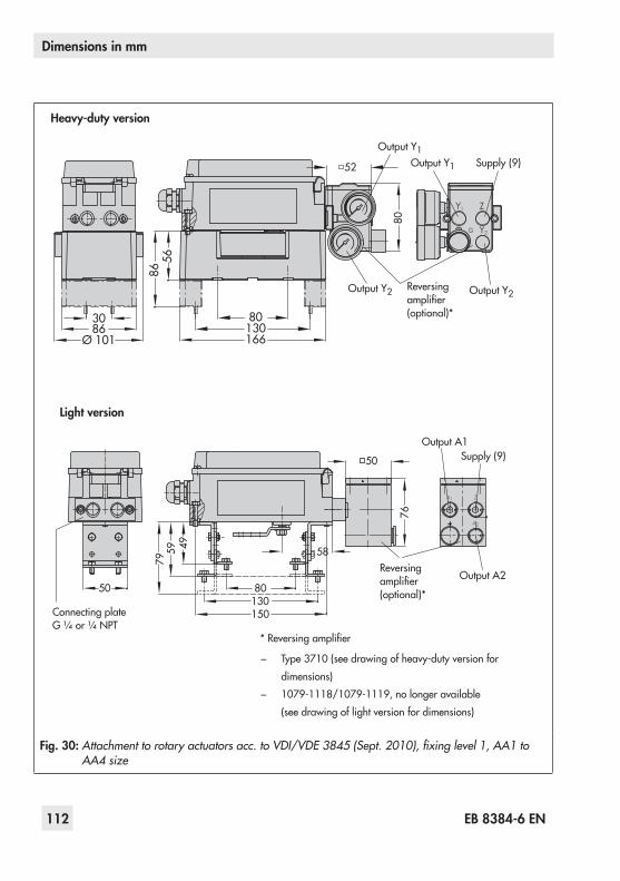
112 EB 8384-6 EN
Dimensions in mm
5686
13080
166
3086
Ø 101
80
52 Output Y1
Output Y2
Supply (9)Output Y1
Output Y2 Reversing amplifier(optional)*
Heavy-duty version
A1 Z
A2
Output A1
Output A2
Supply (9)
50 80
58
130
495979
76
50
150
Reversing amplifier(optional)*
Connecting plate G ¼or¼ NPT
*Reversingamplifier
− Type 3710(seedrawingofheavy-dutyversionfordimensions)
− 1079-1118/1079-1119,nolongeravailable(see drawing of light version for dimensions)
Light version
Fig. 30: Attachment to rotary actuators acc. to VDI/VDE 3845 (Sept. 2010), fixing level 1, AA1 to AA4 size
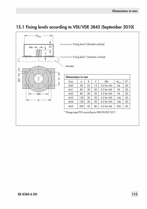
EB 8384-6 EN 113
Dimensions in mm
15.1 Fixing levels according to VDI/VDE 3845 (September 2010)
A
M6
C
B
25
Mmin
Ød
ØD
Fixinglevel2(bracketsurface)
Fixinglevel1(actuatorsurface)
Actuator
Dimensions in mmSize A B C Ød Mmin D*AA0 50 25 15 5.5forM5 66 50AA1 80 30 20 5.5forM5 96 50AA2 80 30 30 5.5forM5 96 50AA3 130 30 30 5.5forM5 146 50AA4 130 30 50 5.5forM5 146 50
AA5 200 50 80 6.5forM6 220 50
*FlangetypeF05accordingtoDIN EN ISO 5211
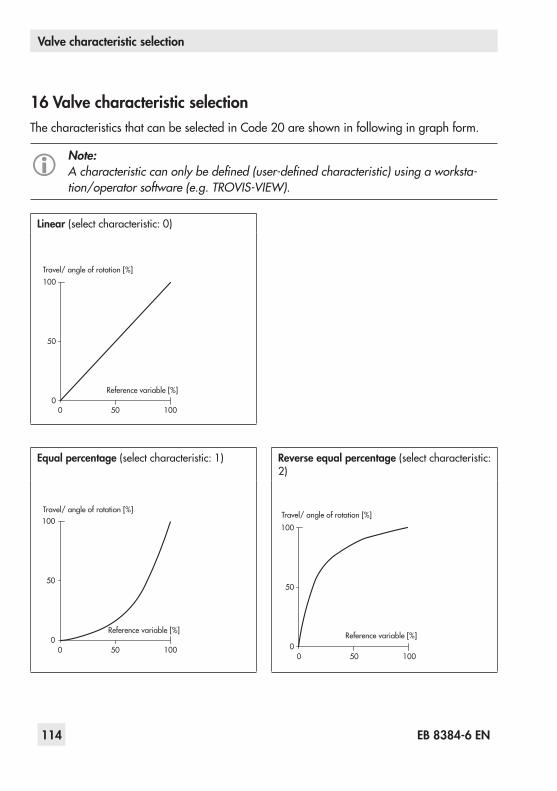
114 EB 8384-6 EN
Valve characteristic selection
Linear (select characteristic: 0)
0
50
100
0 50 100
Travel/ angle of rotation [%]
Reference variable [%]
Equal percentage (select characteristic: 1) Reverse equal percentage (select characteristic: 2)
0
50
100
0 50 100
Travel/ angle of rotation [%]
Reference variable [%]
0
50
100
0 50 100
Travel/ angle of rotation [%]
Reference variable [%]
16 Valve characteristic selectionThe characteristics that can be selected in Code 20 are shown in following in graph form.
Note:A characteristic can only be defined (user-defined characteristic) using a worksta-tion/operator software (e.g. TROVIS-VIEW).

SAMSON butterfly valve linear (select charac-teristic: 3)
SAMSON butterfly valve equal percentage (select characteristic: 4)
0
50
100
0 50 100
Travel/ angle of rotation [%]
Reference variable [%] 0
50
100
0 50 100
Travel/ angle of rotation [%]
Reference variable [%]
VETEC rotary plug valve linear (select char-acteristic: 5)
VETEC rotary plug valve equal percentage (se-lect characteristic: 6)
0
50
100
0 50 100
Travel/ angle of rotation [%]
Reference variable [%]0
50
100
0 50 100
Travel/ angle of rotation [%]
Reference variable [%]
Segmented valve ball linear (select characteristic:7)
Segmented valve ball equal percentage (select characteristic:8)
0
50
100
0 50 100
Travel/ angle of rotation [%]
Reference variable [%]
0
50
100
0 50 100
Travel/ angle of rotation [%]
Reference variable [%]
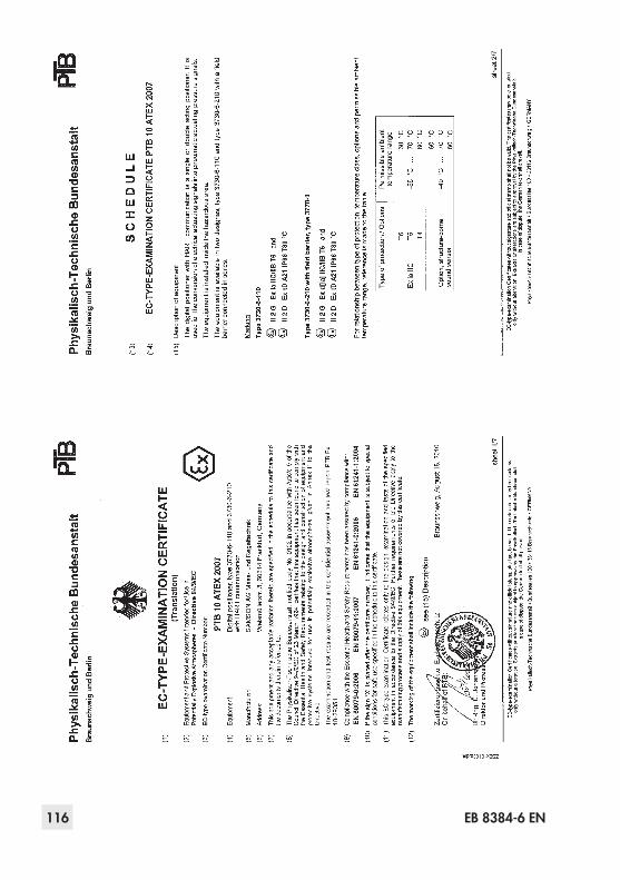
116 EB 8384-6 EN

EB 8384-6 EN 117

118 EB 8384-6 EN
EB 8384-6 EN 119

120 EB 8384-6 EN

EB 8384-6 EN 121

122 EB 8384-6 EN

EB 8384-6 EN 123

SAMSON AG · MESS- UND REGELTECHNIKWeismüllerstraße 3 · 60314 Frankfurt am Main, GermanyPhone: +49 69 4009-0 · Fax: +49 69 [email protected] · www.samson.de EB 8384-6 EN 20
15-02-24·English