series and parallel circuits
TRANSCRIPT

BIOLOGY
Investigation Manual
Series and Parallel Circuits
PHYSICS

KeyPersonal protective equipment (PPE)
goggles gloves apronfollow link to video
photograph results and
submit
stopwatch required
warning corrosion flammable toxic environment health hazard
SERIES AND PARALLEL CIRCUITS
Overview In this investigation, students will build and analyze simple circuits using miniature lamps as resistors. Current flows through a closed circuit. The brightness of the lamps acts as an indicator of the relative current through each loop of the circuit, thus enabling students to understand how voltage and current are used in series and parallel circuits.
Outcomes• Investigate series and parallel circuits• Apply the concepts of Ohm’s law and Kirchhoff’s rules• Develop an understanding of voltage, current, and resistance
Time RequirementsPreparation .................................................................... 10 minutes Activity 1: Resistors in Series ........................................ 15 minutes Activity 2: Resistors in Parallel ...................................... 15 minutes Activity 3: Circuits with Resistors in Series and Parallel #1 .............................................. 15 minutes Activity 4: Circuits with Resistors in Series and Parallel #2 .............................................. 15 minutes Activity 5: Circuits with Resistors in Series and Parallel #3 .............................................. 15 minutes
2 Carolina Distance Learning
Table of Contents
2 Overview 2 Outcomes2 Time Requirements3 Background5 Materials6 Safety6 Preparation8 Activity 110 Activity 211 Activity 311 Activity 412 Activity 513 Disposal and Cleanup13 Observations 15 Data Tables

BackgroundCircuits are an integral part of modern life. Built into the infrastructure of modern towns, circuits carry power to homes and businesses, control the flow of traffic, and extend the number of workable hours by providing light at night. More complicated electrical circuits, such as those found in radios and computers, have intricate circuits that allow them to perform complicated functions, process and transfer complex information, and generally make life more convenient. However, regardless of their complexity, all circuits work according to the same basic principles.
A circuit is a complete path or loop that allows for the transfer of charge. For a charge to flow, the circuit must be complete.
A simple circuit requires three elements:1. A voltage source which provides the force to
move charge through the circuit2. A conductive path which connects the
elements or components in a circuit3. A load or resistance which uses electricity to
do work
The most basic function of a circuit is to transfer charge, which is a physical quantity like mass, time, or distance. There are two types of charge—positive and negative. Objects with like charge repel each other, while objects with dissimilar charge are attracted to each other.
Electrical circuits allow charge to flow through various components connected by wires. This charge is carried by electrons in the metal atoms that compose the wires. The electrons are in constant random motion until an electric field is established, at which point the electrons follow continued on next page
www.carolina.com/distancelearning 3
the electric field. As they move through the circuit, the electrons transfer charge.
The force that drives the charged electrons through a circuit is called an electrical potential or voltage. A battery is a source of electrical potential. When a lamp is connected to a battery, the difference in electrical potential between the positive and negative side of the battery draws the negatively charged electrons through the circuit, providing energy to light the lamp. When a circuit is complete, the electrical potential or voltage causes charge to move through the circuit. This movement of charge is called a current. Electrical current is simply an expression of the number of electrons passing a certain point in the circuit in a certain amount of time. The amount of current is measured in Amperes, which is abbreviated as amp (A). An amp is equal to the number of coulombs (a unit of charge) per second.
[A] = C
One coulomb (C) is a very large amount of charge. For example, an average lightning bolt may transfer approximately 15 coulombs of charge. The elementary charge is the charge of one electron (e), which is equal to 1.602 × 10⁻¹⁹ C. The current moving through a circuit is often measured in milliamps (1 mA = 1 A × 10-3) or microamps (1 μA = 1 A × 10-6). These relatively small units demonstrate that miniscule amounts of charge flow through circuits at any time. However, some circuits, such as those carried by power lines, conduct large currents and can be dangerous.
Voltage and current are related to each other through another quantity called resistance,
s

Background continued
4 Carolina Distance Learning
one direction. Batteries provide a source of a direct current. The current delivered from power stations is an Alternating Current (AC) which is a current that oscillates back and forth between a positive and negative voltage, changing directions very quickly. The advantage to having an alternating current is that it can be transmitted over greater distances without losing much energy. Electrical devices that require a direct current have power supplies that transform the AC output from wall outlets to a lower voltage, as well as convert the current to DC.
which is a measure of how much an object opposes the flow of current. This relationship is described by Ohm’s law, which states
V = IR
V = voltage (electrical potential, measured in Volts [V])
I = current (measured in Amperes or amps [A]) R = resistance (measured in Ohms [Ω])
Figure 1 shows the simplest circuit. The lines in the diagram represent wires, while the arrow indicates the flow of current. The symbol in Figure 2 represents a resistor, and the symbol in Figure 3 represents a voltage source.
In Figure 3, the longer line represents the positive terminal and the shorter line represents the negative terminal.
The circuits shown throughout this lab are Direct Current (DC) circuits, which entail any given loop of the circuit having the current flowing in
SERIES AND PARALLEL CIRCUITS
Note: When analyzing and drawing circuits, the direction of current follows the flow of positive charges. This is known as “conventional current.” In reality, the positive charges in atoms are due to the protons in the nucleus, which do not move when a circuit is connected. When a circuit is connected, it is the electrons in the outer energy levels of atoms that move. The electrons carry a negative charge, so electric current is a flow of negative charge. When this happens, it has the net effect of a positive charge flowing in the opposite direction. Electrical power systems and appliances were already in wide use before this discovery was made, and it had been assumed that current was due to a flow of positive charge; so by convention, people agreed to keep using positive current. The arrows indicating the flow of current on diagrams in this document are all indicating the flow of positive,“conventional” current.
Figure 1.
continued on next page
Figure 3. Figure 2.

www.carolina.com/distancelearning 5
When different components or devices are connected in a circuit, they draw energy. This energy can be used to run a motor or power a computer, but in all cases, some of this energy is converted to heat. A light lamp converts electrical energy to heat and light. The intensity of a light lamp, which is indicated through its brightness, depends on the power dissipated throughout the lamp. The power dissipated through the lamp, or any resistor, depends on the voltage across this resistor and the current through the resistor.
P = VIP = power (measured in Watts [W])V = voltage (electrical potential, measured in
Volts [V])I = current (measured in Amperes or amps [A])
Just like mechanical energy, power translates into Joules per second, demonstrating that it is a measure of energy per unit time.
[P] = [V][S] = J.C = J = W
In addition to Ohm’s law, Kirchhoff’s rules can be used for analyzing voltage and current in a circuit:1. Kirchhoff’s voltage rule:
The sum of the electrical potential differences around any closed loop in a circuit is zero.
2. Kirchhoff’s current rule: The current flowing into a junction must equal the current flowing out of a junction.
The following labs in this manual include a series of increasingly complex circuits that will illustrate the relationship and differences between voltage and current by applying the principles of Ohm’s law and Kirchhoff’s rules.
C s s
MaterialsIncluded in the materials kit:
Reorder Information: Replacement supplies for the Series and Parallel Circuits investigation (item number 580410) can be ordered from Carolina Biological Supply Company.
Call: 800.334.5551 to order.
Needed but not supplied:• Scissors• Ruler• Tape (recommended but not
required
5 Lamp sockets
10 Miniature lamps
Sandpaper
2 Alligator clips/black electrodes
Magnetic wire,#28
D cell batteries
5 Battery holders

SERIES AND PARALLEL CIRCUITS
6 Carolina Distance Learning
Safety goggles should be worn during this investigation. There are no additional safety concerns.
Read all of the instructions for this laboratory activity before starting the activity. Follow the instructions closely and observe established laboratory safety practices, including the use of appropriate personal protective equipment (PPE) described in the Safety and Procedure section.
The components included in this kit use low voltage and current and are safe to handle. Do not substitute other components with this kit.
Connecting circuits for extended periods of time can cause wires or components to overheat or batteries to leak. Keep the circuits connected only as long as is needed to complete the analysis, and then disconnect the alligator clip from the batteries.
Do not eat, drink, or chew gum while performing this activity. Wash your hands with soap and water before and after performing the activity. Clean up the work area with soap and water after completing the investigation. Keep pets and children away from lab materials and equipment.
PreparationThe circuits in these activities use lamps as resistors. All of the lamps and sockets are identical so that each lamp can be considered to have a resistance of “R” Ohms.
Diagrams are included to show the circuits representing the lamps with the resistor symbol and the battery with the voltage symbol. Photographs are also included of the assembled circuits showing exactly how the lamp sockets are connected.
There is one voltage source in each circuit, which can be considered as having volts (V).
By adding resistors and loops to the circuit, the current through the lamps and voltage across the lamps will change.
Since the brightness of the lamp depends on power, and power depends on current and voltage, changing the current and voltage in different parts of the circuit will change the relative brightness of the lamps.
1. Use scissors to cut the copper wire into 10 strips that are each 10 cm long.
2. Use the sandpaper to remove the enamel from the last 3 cm of each end of each piece of wire. Make sure the enamel is cleared
Safety
Note: The brightness of the lamps depends on power, which depends on both current and voltage. Power through a resistor is represented as:
P = VI = V2 = I2RR
www.carolina.com/distancelearning 7
from all sides of the wire. Watch the following video on how to strip magnet wire.
How to Strip Magnet Wire https://players.brightcove.net/17907428001/HJ2y9UNi_default/index.html?videoId=45734121650013
3. Insert a battery into a battery holder.
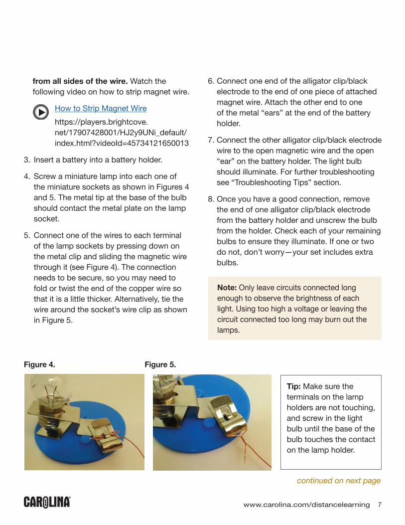
4. Screw a miniature lamp into each one of the miniature sockets as shown in Figures 4 and 5. The metal tip at the base of the bulb should contact the metal plate on the lamp socket.
5. Connect one of the wires to each terminal of the lamp sockets by pressing down on the metal clip and sliding the magnetic wire through it (see Figure 4). The connection needs to be secure, so you may need to fold or twist the end of the copper wire so that it is a little thicker. Alternatively, tie the wire around the socket’s wire clip as shown in Figure 5.
Tip: Make sure the terminals on the lamp holders are not touching, and screw in the light bulb until the base of the bulb touches the contact on the lamp holder.
Figure 4. Figure 5.
6. Connect one end of the alligator clip/black electrode to the end of one piece of attached magnet wire. Attach the other end to one of the metal “ears” at the end of the battery holder.
7. Connect the other alligator clip/black electrode wire to the open magnetic wire and the open “ear” on the battery holder. The light bulb should illuminate. For further troubleshooting see “Troubleshooting Tips” section.
8. Once you have a good connection, remove the end of one alligator clip/black electrode from the battery holder and unscrew the bulb from the holder. Check each of your remaining bulbs to ensure they illuminate. If one or two do not, don’t worry—your set includes extra bulbs.
continued on next page
Note: Only leave circuits connected long enough to observe the brightness of each light. Using too high a voltage or leaving the circuit connected too long may burn out the lamps.
Troubleshooting Tips: If at any time you feel the bulb is too dim to see, troubleshoot using the following steps:a. Make sure the bulb is neither loose nor
off-center. If you suspect a bulb is defective or may have burned out, use the circuit shown in Figures 7 and 8 to test the bulb. If the bulb does not work, replace it.
b. Ensure that the wires and other circuit components all have stable connections. You may need to pull gently on the wires to tighten the connections. Once the connection is stable, you may wish to tape the lamp sockets to the work surface to help hold the circuit together.
c. If Steps a and b do not work, then add one additional battery and battery holder to the system. The battery holders snap together. The alligator clips should attach to the outermost “ears” on the holder, as shown in Figure 6. Add just one battery and holder at a time until the bulb brightens. Connecting an excessive number of batteries without testing may blow out the bulb.
8 Carolina Distance Learning
ACTIVITY 1
continued on next page
Resistors in Series
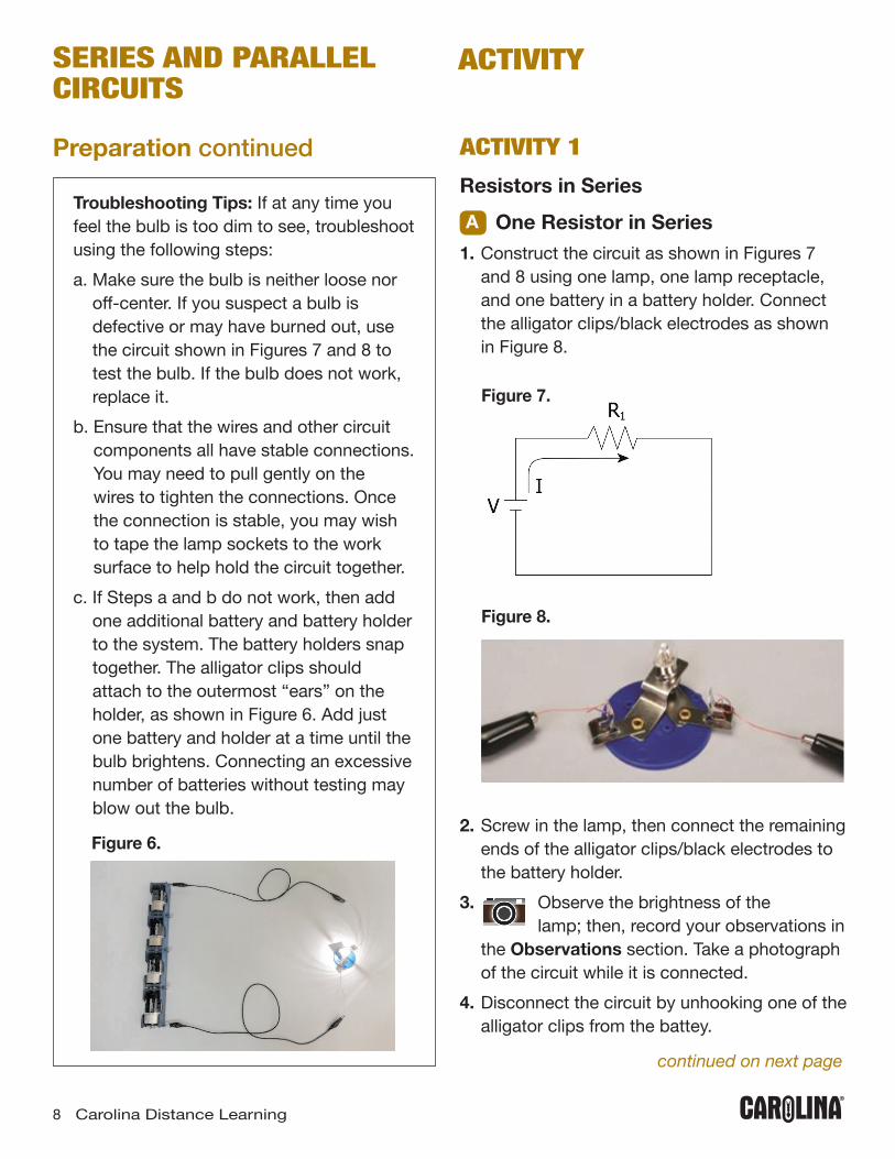
A One Resistor in Series1. Construct the circuit as shown in Figures 7
and 8 using one lamp, one lamp receptacle, and one battery in a battery holder. Connect the alligator clips/black electrodes as shown in Figure 8.
ACTIVITY
Figure 8.
Figure 7.
2. Screw in the lamp, then connect the remaining ends of the alligator clips/black electrodes to the battery holder.
3. Observe the brightness of the lamp; then, record your observations in
the Observations section. Take a photograph of the circuit while it is connected.
4. Disconnect the circuit by unhooking one of the alligator clips from the battey.
Preparation continued
SERIES AND PARALLEL CIRCUITS
Figure 6.

B Two Resistors in Series1. Assemble a circuit with two lamps in series as
shown in Figures 9 and 10. Connect the wires by twisting them together as shown in Figure 10.
2. Photograph the circuit while all the lamps are connected.
3. Unscrew the lamp in the position of R1. Photograph the circuit and record your observations in the Observations section.
4. Disconnect the circuit by unhooking one of the alligator clips from the battery pack.
Figure 9.
www.carolina.com/distancelearning 9
Note: The circuit constructed for Activity 1A may be set aside. It may be necessary to use this circuit in other investigations to check a bulb to see if it is burned out or is still functional.
Figure 10.
Figure 11.
Figure 12.
C Three Resistors in Series1. Connect three lamps in series as shown in
Figures 11 and 12.2. Observe the brightness of the lamps; then,
record your observations in the Observations section.
3. Photograph the circuit while all of the lamps are connected.
4. Unscrew the lamp at position of R1, and observe what happens to the remaining lamps. Photograph the circuit and record your observations in the Observations section.
5. Disconnect the circuit by removing one of the alligator clips from the batteries.

ACTIVITY
10 Carolina Distance Learning
Figure 13.
Figure 14.
ACTIVITY 2
Resistors in Parallel
A Two Resistors in Parallel1. Connect two lamps in parallel as shown in
Figures 13 and 14.2. Connect the two lamps to the battery pack. 3. Observe the brightness of the lamps; then,
record your observations in the Observations section.
4. Photograph the circuit with all of the lamps connected.
5. Unscrew the lamp in the position of R1. Photograph the circuit and record your observations in the Observations section.
6. Disconnect the circuit by removing one of the alligator clips from the batteries.
B Three Resistors in Parallel1. Connect three lamps in parallel as shown in
Figures 15 and 16.2. Observe the brightness of the lamps.
Photograph the circuit and record your observations in the Observations section.
3. Disconnect the lamp in the position of R1. Photograph the circuit and
record your observations in the Observations section.
4. Disconnect the circuit by removing one of the alligator clips from the batteries.
Figure 15.
Figure 16.

www.carolina.com/distancelearning 11
ACTIVITY 3
Circuits with Resistors in Series and Parallel #11. Construct the circuit as shown in Figures 17
and 18. 2. Observe the brightness of the
lamps. Photograph the circuit while all of the lamps are connected and record your observations in the Observations section.
3. Disconnect the lamp in the position of R1.4. Disconnect the lamp in the position of
R1. Photograph the circuit and record your observations in the Observations section.
5. Reconnect the lamp in position R1. 6. Disconnect the lamp in position R2.
Photograph the circuit and record your observations in the Observations section.
7. Disconnect the circuit by removing one of the alligator clips from the batteries.
ACTIVITY 4
Circuits with Resistors in Series and Parallel #21. Construct the circuit as shown in Figures 19
and 20. 2. Photograph the circuit while all of the
lamps are connected.
Figure 18.
continued on next page
Figure 20.
Figure 17. Figure 19.

ACTIVITY
12 Carolina Distance Learning
3. In Data Table 1, write the name of the remaining resistors in order from brightest to dimmest.
4. Disconnect the lamp in position R1. Observe the brightness of the lamps and photograph the circuit.
5. In Data Table 2, write the name of the remaining resistors in order from brightest to dimmest.
6. Reconnect resistor R1.7. Disconnect resistor R2 and take a
photograph of the circuit.8. In Data Table 3, write the name of each
resistor in order from brightest to dimmest.9. Reconnect resistor R2.10. Disconnect resistor R4 and
photograph the circuit.11. In Data Table 4, write the name of each
resistor in order from brightest to dimmest.12. Disconnect the circuit by unhooking one of
the alligator clips from the battery pack.13. Record your observations in the
Observations section.
ACTIVITY 5
Circuits with Resistors in Series and Parallel #31. Construct the circuit as shown in Figures 21
and 22. 2. Observe the brightness of each
lamp. Record your observations in the Observations section. Photograph the circuit with all the lamps connected. In Data Table 5, write the name of each resistor in order from brightest to dimmest.
Figure 21.
Figure 22.
continued on next page
ACTIVITY 4 continued

continued on next page
www.carolina.com/distancelearning 13
3. Disconnect resistor R1. Observe the brightness of the lamps. Photograph the circuit and record your observations in the Observations section.
4. In Data Table 6, write the name ofthe remaining resistors in order from brightest to dimmest.
5. Reconnect resistor R1.6. Disconnect resistor R3. Observe
the brightness of the lamps. Photograph the circuit and record your observations in the Observations section.
7. In Data Table 7, write the name of each resistor in order from brightest to dimmest.
8. Disconnect the circuit by unhooking one of the alligator clips from the battery pack.
Disposal and CleanupMake sure the alligator clips are detached from the terminal. Carefully unscrew the lamps from the socket. Put them back in the lamp container. Dispose of any burned out lamps in the trash receptacle. Take the batteries out of the battery holder. Put everything back into the materials kit. Clean up the work area.
Observations Activity 1A:
Activity 1B:
Activity 1C:

ACTIVITY
14 Carolina Distance Learning
Observations Activity 2A:
Activity 2B:
Activity 3:
Activity 4:
Activity 5:

www.carolina.com/distancelearning 15
Data Table 1. All Lamps are Connected
Data Table 2. Effect of Disconnecting Resistor R1
Data Table 3. Effect of Disconnecting Resistor R2
Data Table 4. Effect of Disconnecting Resistor R4
Brightest Lamp(s)
Next Brightest
Next Brightest
Least Bright
Brightest Lamp(s)
Next Brightest
Next Brightest
Least Bright
Brightest Lamp(s)
Next Brightest
Next Brightest
Least Bright
Brightest Lamp(s)
Next Brightest
Next Brightest
Least Bright
Data Table 5. All Lamps are Connected
Data Table 6. Resistor R1 is Disconnected
Data Table 7. Resistor R3 is Disconnected
Brightest Lamp(s)
Next Brightest
Next Brightest
Least Bright
Brightest Lamp(s)
Next Brightest
Next Brightest
Least Bright
Brightest Lamp(s)
Next Brightest
Next Brightest
Least Bright
Data Tables

PHYSICS Series and Parallel Circuits
Investigation Manual
www.carolina.com/distancelearning 866.332.4478
Carolina Biological Supply Companywww.carolina.com • 800.334.5551©2019 Carolina Biological Supply Company
CB780971906