series dvr/user manual/dvr... · web viewafter booting the system will automatically format the...
TRANSCRIPT
H.264 Digital Video Recorder
Operation Instruction

Directory1 Precautions.....................................................................................................................................12 Statement.......................................................................................................................................23 Introduction....................................................................................................................................3
3.1 Introduction.........................................................................................................................33.2 Product features...........................................................................................................33.3 Installation Guide.........................................................................................................4
3.3.1 Unpacking Inspection.......................................................................................43.3.2 Hard disk installation.......................................................................................43.3.3 Wiring Installation.............................................................................................53.4 Panel Introduction................................................................................................53.4.1 Front Panel Description...................................................................................53.5 Mouse operation.................................................................................................133.6 Input Method........................................................................................................143.7 Boot/Shutdown....................................................................................................153.7.1 Boot......................................................................................................................153.8 Screen icon...........................................................................................................163.8.1 Status Icons.......................................................................................................163.9 Real-time browser..............................................................................................17
4 Operations Guide..................................................................................................................184.1 Right-click menu................................................................................................................18
4.1.1 Screen switching..............................................................................................194.1.2 PTZ control.........................................................................................................194.1.3 Image Color.......................................................................................................194.1.4 Video inquiry.....................................................................................................204.1.5 Manual recording.............................................................................................204.1.6 Alarm output.....................................................................................................204.1.7 Main menu.........................................................................................................20
4.2 Main menu introduction...........................................................................................214.3 Video queries...............................................................................................................224.4 Configuration management..............................................................................23
4.4.1 System configuration.....................................................................................244.4.2 Video configuration.........................................................................................264.4.3 Network Configuration...................................................................................294.4.4 Alarm configuration.................................................................................314.4.5 User Management...........................................................................................344.4.6 Abnormal configuration.................................................................................36
4.5 Storage Management...............................................................................................374.5.1 Hard disk management.........................................................................................37
4.5.2 Video backup.....................................................................................................394.6 Peripheral Management...........................................................................................41
4.6.1 PTZ Configuration..............................................................................................414.6.2 Serial port configuration...............................................................................42

4.6.3 Output mode.....................................................................................................434.7 Maintenance and management............................................................................46
4.7.1 Log information................................................................................................464.7.2 Version information.........................................................................................474.7.3 Restore the default.........................................................................................474.7.4 Stream statistics..............................................................................................484.7.5 Automatic maintenance................................................................................484.7.6 Online Users......................................................................................................48
4.8 Turn off the device.....................................................................................................495 WEB and client.......................................................................................................................50
5.1 WEB operation.............................................................................................................505.1.1 Network connection................................................................................................50
5.1.2 Control installation and user login logout..............................................505.1.3 WEB operator interface................................................................................525.1.4 Real - time video surveillance.....................................................................525.1.5 PTZ control.........................................................................................................545.1.6 System Configuration....................................................................................555.1.7 Video inquiry.....................................................................................................565.1.8 Alarm settings...................................................................................................575.1.9 About....................................................................................................................57
5.2 Client operating..........................................................................................................586 Extended functionality........................................................................................................58
6.1 DDNS function.............................................................................................................586.1.1 Outline.................................................................................................................586.1.2 VSSIP......................................................................................................................586.1.3 3322 DDNS.............................................................................................................586.1.4 NO-IP(www.no-ip.com)....................................................................................596.1.5 Dyndns DDNS(www.dyndns.com).........................................................................596.1.6 Dynamic DNS verification.............................................................................60
6.2 Port mapping................................................................................................................616.2.1 UPnP function....................................................................................................616.2.2 Manual port mapping.....................................................................................62
6.3 NTP function.................................................................................................................636.3.1 Internet network environment settings...................................................636.3.2 Private network environment settings.....................................................63
6.4 PTZ function.................................................................................................................636.5 Voice intercom.............................................................................................................67
6.5.1 Outline.................................................................................................................676.5.2 Configuration method....................................................................................68
6.6 Hard disk redundancy...............................................................................................686.7 Hard S.MA.R.T technology.......................................................................................69
7 Appendix..................................................................................................................................717.1 Term..................................................................................................................................71
7.1.1 I-frames...............................................................................................................71

7.1.2 B-frames.............................................................................................................717.1.3 P-frames..............................................................................................................717.1.4 S.M.A.R.T technology.....................................................................................727.1.5 VCBS.......................................................................................................................727.1.6 BNC........................................................................................................................72
7.2 Hard disk calculated and maintenance..............................................................727.2.1 Hard disk capacity is calculated with reference to.............................727.2.2 Hard Troubleshooting.....................................................................................737.2.3 Common Troubleshooting.............................................................................75

1 Precautions
1. This video recorder is powered by utility power through DC12V adapter,
please check the power supply of power socket to see if it meets the
requirement of the adapter before installation is carried out;
2. Never place the video recorder at humid place or place subject to rain;
3. The video recorder should be installed at a place without strong vibration;
4. The video recorder should be installed at a place without direct sunlight and
far away from heat source and high temperature;
5. When the video recorder is installed, its rear panel should be more than 15cm
away from other object or wall to facilitate heat emission by fan;
6. Allow the video recorder to work within the temperature, humidity, and
voltage ranges permitted by the technical criteria;
7. Never store chemicals from which corrosive and volatile gas may be created
in the place where the video recorder is installed, lest the service life of video
recorder will be affected;
8. The video recorder should not installed where there are many dusts, and the
surrounding environment should be kept clean;
9. When the video recorder is used, correct grounding should be ensured;
10. When the video recorder is installed, correct connection to other devices
should be ensured;
11. Please purchase hard disk from formal channel, so as to suit long term, mass
data read-write requirement of DVR;

2 Statement
Copyright ©2012
Any extraction, reproduction or distribution of this manual in part or
in whole by any company or any individual is prohibited without written
consent of our company.
The content of this manual will be updated at any time without
notice as a result of product version upgrade or other reasons. Except
otherwise specified, this manual is only used for application guidance,
and all descriptions, information and recommendation in this manual will
not constitute any expressed or implied warranty.
3 Introduction
3.1 Introduction
This product is a designed for video surveillance video encode and record, it include H.264 video Compression, large HDD storage , network , embedded Linux
operate system and other advanced electronic technology,realized a high - quality , low bit rate video features and good stability of the system .
The products comply with GB 20,815 at the national award of the video surveillance digital video recording equipment standards. This product has a variety of functions, simultaneous recording, playback, monitor, implement audio and video synchronization, with advanced control technology and a strong network of data transmission capacity.
3.2 Product features
Real-time monitoring:Have a composite video signal interface, supports TV, VGA, or HDMI output simultaneously.
Compression processing functions:Using H.264 video compression standard and G.711 audio compression standard, and supports up to D1 resolution encoding.
Video feature:Support timing, alarm linkage, dynamic detection of a variety of business video mode , support for
SATA hard drive and the local hard S.MA.R.TR technology , providing USB interface backup and
network backup functions for DVR data .
Video playback function:Can be realized by a variety of criteria to retrieve videos for local and network playback; support
multi-channel video while playback fast forward, slow forward, rewind and frame-by-frame
playback mode; The playback of video can show the exact time of the incident .
Camera control with alarm:Support for remote camera control: With multi-channel alarm input port, can connect all kinds of
alerting devices; with dynamic detection, video loss video alarm function; multi-channel alarm
output, alarm linkage and lighting control can be realized.
Communication interface:With USB2.0 high speed interface or the SATA interface, external backup devices; with standard
Ethernet interfaces, Plug-and-play under various network conditions.
Network functions:Supports TCP/IP, UDP, RTP/RTSP, and DHCP, PPPoE, DDNS, NTP, a wealth of network protocols;

support network real-time monitoring, video playback, control and management functions; a built-in
WEB Server, accessible from a browser can be accessed directly.
Mode of operation:Support multiple operation modes, such as front panel , remote control, mouse; with a simple and
intuitive graphical interface.
3.3 Installation Guide
3.3.1 Unpacking Inspection
Please inventory according to the packing list inside the box when you receive the product.
3.3.2 Hard disk installation
Preparing for Installation:
You need a Phillips screwdriver.
Note: The number of drives supported by each model DVR subject to the corresponding product
specification sheet maximum hard disk capacity of 64TB.
Hard disk installation steps:
Open the screw on the side of the chassis , and open the the hard screw holes on the chassis cover
using screws to secure the hard disk in the inquiry or the hard disk bracket; Connected hard drive data
cable and power cord;
Cover chassis cover with the screws.
Precautions:
Select the hard drive manufacturer's recommended requirements for DVR hard drive.
After booting the system will automatically format the hard disk , the original data in the hard disk may
be lost completely .
Hard drive capacity and video parameters configuration will affect the total length of videos saved,
reference 7.2 reference calculation on the total capacity of the installed hard disk
3.3.3 Wiring Installation
Installation preparation:
Be ready to video cameras, monitors, video cable, network cable, mouse, and power lines. Installation
steps:
To rotate the level of DVR, the video input source to video input connector on the back of the DVR;
DVR video output to display devices on the device-side;
If you want to use the network, please plug the network cable to the RJ45 interface;
Mouse with USB type you want, you can insert any of the front and back panel USB interface connected
to the DVR power.
Note:
If you need an external alarm device or platform, please refer to the Setup instructions related content.
Power on the DVR should be in connection with all lines are connected.
When the power is connected, please note the power parameter.
3.5 Mouse operation
Real time screen monitoring, click the left mouse button to access the main menu: If the user has not
logged on to the system, you pop up a password entry box.
Click a the functions menu option icon to enter the menu.
Perform the operation on the specified control.
Change the state of the check box dynamically detect block.
Click combo box pop-up drop-down list.
PTZ 3D under controlled conditions, click to the left to lower-right drag box selected, you achieve PTZ
3D control zoom feature: dragging from right to left, implementing PTZ 3D control narrow features,
detailed zoom effects please view 4.1.2 PTZ control section of introduction.
Double - click the left mouse button.
Select and confirm, open, for example , double - click the playback sometime recording.
Multi- screen double-click the left mouse button to turn into full screen again double-click the single
screen full screen of the screen; revert to a previous multi- screen state.
Click the right mouse buttonReal-time monitoring screen pop-up right menuThe contents of the menu in the menu interface do not save and exit the
current menu.
Turn the wheelTurning the mouse wheel to increase or decrease the digital frame digital box set numerical values .Switch the option of the combo box.Flip up and down list box.Scroll back and forth, PTZ 3D zoom function.
Mouse movementSelected the current coordinate control or control a particular move.
Mouse dragMarquee motion detection area.Marquee locale regional coverage.Marquee zoom 3D PTZ control function.

3.6 Input Method
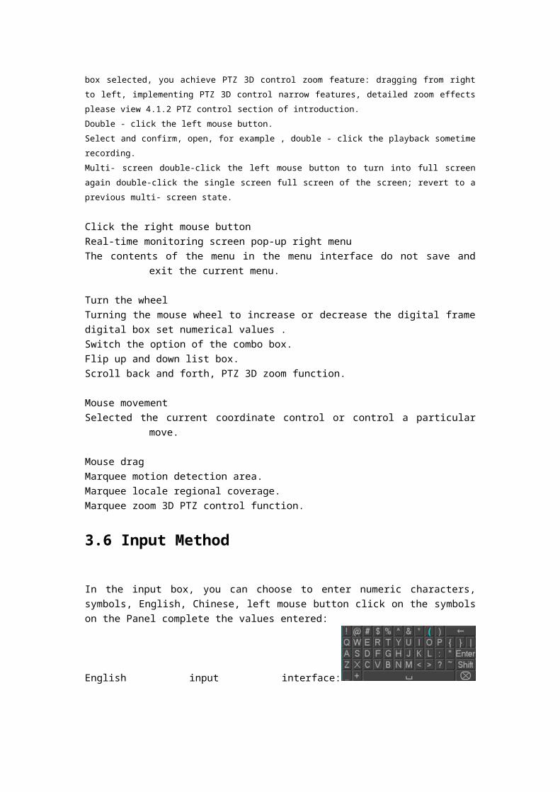
In the input box, you can choose to enter numeric characters, symbols, English, Chinese, left mouse button click on the symbols on the Panel complete the values entered:
English input interface:
Chinese input interface:
Digital input interface:
Special symbols Interface:
3.7 Boot/Shutdown
3.7.1 Boot
DVR is correctly installed and plugged in, the power led is lit, video recorder will automatically turn on. Show slightly different under different types of device power state , please refer to the

front panel section of this article.DVR boot process will automatically detect the device hardware state, boot process takes about 20 seconds. Power-on complete devices after the buzzer was given a "beep" tone, and enter the screen real-time video surveillance state, equipment operation or configuration can be at this time. Please refer to 4.2 main menu introduction and subsequent introduction.If the start-up time within the video to set the time, the system will automatically start a scheduled recording function.Note: Please use the DVR power supplied, you may not use other types of branded power supply instead of the original power supply.
3.7.2 Shutdown
When Shutdown, direct to Unplug the power. orInto the "main menu" - > "Close System" - > select "Shutdown”
Note: replace the hard disk operation should be off the device and disconnect the power before proceeding.
3.7.3 Power recovery
When the video recorder video work under the State, system power supply has been cut off or been forced to shut down, after you reconnect the power, VCRs are automatically saved before
the power of video, and automatic restoration of power of state continue to work.
3.8 Screen icon
3.8.1 Status Icons
:This flag is displayed on the channel screen monitor channel video.
:Channel video loss occurs, the channel screen display this flag.
:Dynamic detection occurs, the channel screen display this flag.
:The channel is monitoring the locked state, this flag is displayed on the channel screen.
: Allows the screen to switch polling.
3.8.2 Operator Logos
:Enable box unchecked.
:Enabled box is checked state.
:Transferred out of the drop-down menu
:Determined to modify the settings / menu to enter
:Set / cancel to cancel the change to enter the menu.
: To set the parameters.
:Save the current set of parameters.
:Default factory settings, modify parameters, click on the button to return to the last set of parameters.
:The current set of parameters is applied to the system.

:The current set of parameters are copied to the other channel.
:Enter the parameter configuration menu.
: Selection and configuration of the alarm, the processing operation of the video detection trigger.
3.9 Real-time browser
Devices start correctly after entering the monitor screen in real time, each screen superimposed on the
date, time, channel name, the bottom of the screen there is a line for each channel of video and alarm
status icon. Also accessible through the front panel, the remote control or the right and left mouse button
double-click the screen switch operation.
If you set the external alarm system, video loss, occlusion detection, dynamic, IP conflict detection,
network cable connection screen, when the alarm occurs, under real-time monitoring screen will pop up
prompting interface, as shown in figure:

4 Operations Guide
4.1 Right-click menu
Boot, after entering the viewing interface in real time, click the right mouse button, a pop-up action menu;
4.1.1 Screen switching
4 channels, you can watch channels as needed, single-screen, Quad-screen, screen and 16 display adjustment
4.1.2 PTZ control
DVR's "peripherals management" "PTZ configure" PTZ Protocol, baud rate, address and other parameters set, click on the "PTZ control", you can control the PTZ, details see 6.4 PTZ functions.
4.1.3 Image Color
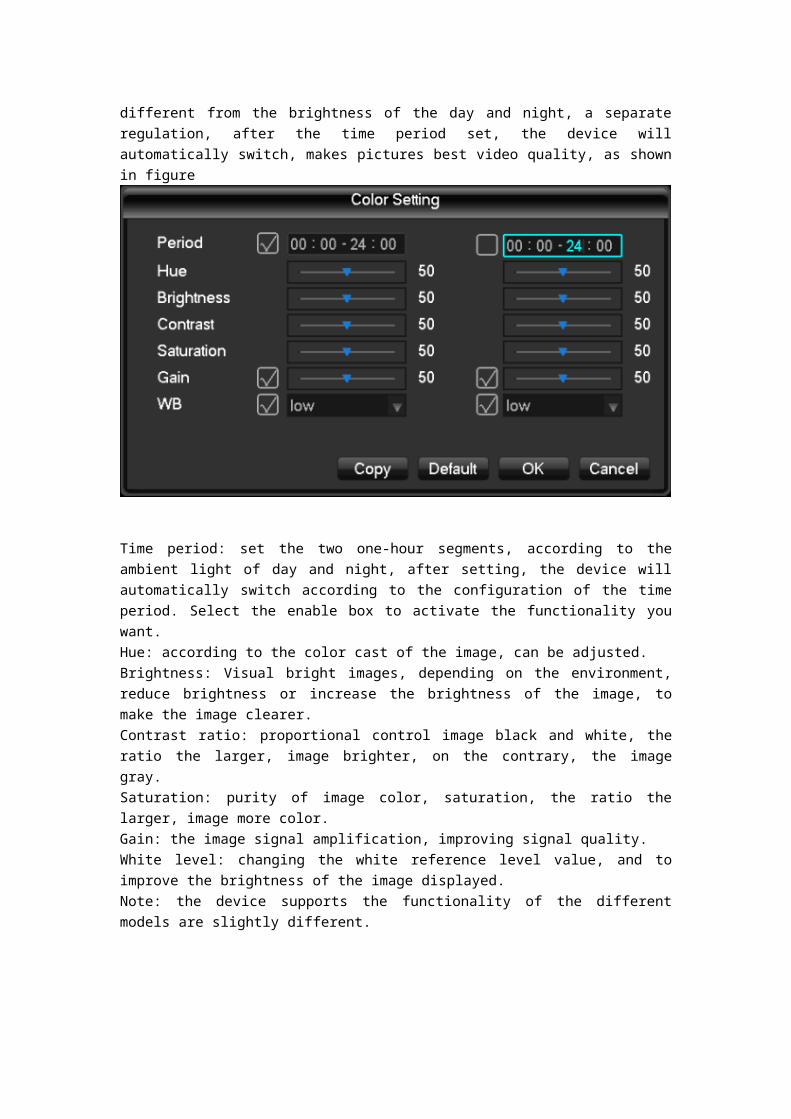
Adjust the specified screen (single screen) image color hue, brightness, contrast, saturation, gain, and white-level parameters, set two time periods, according to local environment different from the brightness of the day and night, a separate regulation, after the time period set, the device will automatically switch, makes pictures best video quality, as shown in figure

Time period: set the two one-hour segments, according to the ambient light of day and night, after setting, the device will automatically switch according to the configuration of the time period. Select the enable box to activate the functionality you want.Hue: according to the color cast of the image, can be adjusted.Brightness: Visual bright images, depending on the environment, reduce brightness or increase the brightness of the image, to make the image clearer.Contrast ratio: proportional control image black and white, the ratio the larger, image brighter, on the contrary, the image gray.Saturation: purity of image color, saturation, the ratio the larger, image more color.Gain: the image signal amplification, improving signal quality.White level: changing the white reference level value, and to improve the brightness of the image displayed.Note: the device supports the functionality of the different models are slightly different.
4.1.4 Video inquiry
4.1.5 Manual recording
Tip: manual recording operation requires the user to have a "video" operating authority. Under real-time monitoring screen, click the right mouse button, click on the "manual recording", or press "video" keys to go directly to the manual recording interface.

[Manually] With highest priority, regardless of what each channel in status, do the "manual" button, the corresponding channel all ordinary video.[Auto] Video by the video settings in the settings (normal, dynamic detection and alarm) the video type video.[Close] All channels stop recording.To change the state of a channel of videos, first check the video channel is selected, or in select State (non-select status indicates that the channel is not in the video status parameters select the status indicates that the channel is in the video). And then use the mouse to click, or use the left or right arrow keys to move the active box to the channel, then use the up or down arrow keys or the numeric keys, switch the channel video.Note: Select Enable can also change the video status of all channels.
4.1.6 Alarm output
4.1.7 Main menu
Click on the "main menu", users enter a user name and password in the box, click "OK" to enter the system menu.
The factory default users are as follows:Administrator user adminPassword 123456

Ordinary users UserHide User DefaultNote: password security measures: wrong password entered incorrectly 3 times device will beep after alarm, 5 times your account will be locked, and account lockout after 30 minutes automatically recover, for security reasons, please timely change the factory default password. Adding user groups, users, and modify the users see 4.4.5 of the user management, mouse operation, click on the "123" button to switch input method.
4.2 Main menu introduction
System main menu, main video control, video configuration, video backup cloud configuration, hard disk, network configuration, configuring the alarm configuration and system settings. [Recording control] recording modes including automatic, manual, 3 modes on and off.[Video configuration] set up video information, including recording basic information and recording plans. [Video backing up] the use of peripheral equipment for video backup. [Network configuration] setting various parameters associated with the network. [PTZ configuration] parameters of the pan. [Disk management] information on managing hard disks. [P2P QRCode] View cloud service connection status, see the serial number, download the mobile client software. [System settings] setting system, user and output configuration.4.3 Video queries
4.3 Video queries
Under real-time monitoring screen, click the right mouse button, click on the [video query], or through
the main menu to enter the video playback interface; Video query interfaces are described below:
Number 1 Calendar Click on the calendar icon will display a user video recording (Green fill indicates
that on that day, video, no fill that day without video), and then click on the date for which you want to
view, the file list will be automatically updated to the file list for the day
Number 2 Time select Select video query start time; click on the play button, select all channel
playback from that point.
Number 3 Playback controls Control video playback, enabling pause / play, rewind, stop, rewind, fast
release, the last frame, next frame pause state.
Number 4 Query video type selection Select the desired query type of video, including: all, all
external alarm, motion detection, alarm recording.
Number 5 Query channel selection Select the desired query type of video, including: full, alert,
dynamic testing, all of external alarm recording.
Number 6 Playback controls Select full screen, start / end clip, clip file backup, playback of video
control, display the playback status.
Number 7 Inquiry Select the end time after query, query channel, click on the query will display the
query results in the video list.
Number 8 Backup In file list box in the select user needs backup of file, in list box in the playing hook
can check (can in two a channel while select needs backup of file), again click Backup button, appears

backup operation menu, click Backup button to, user also can in backup operation menu in the canceled
don't want to backup of file, in to canceled of file list box before canceled hook (single channel displayed
list number for 128)
Number 9 Video list Display the query results in the video to the video list box displays a list of. 128
query time lists displayed on the screen of video files, you can press the up or down keys to view video
files, or drag the mouse wheel up or down to view video files. Select the files you want, press ENTER or
double click the left mouse button to start playing the video file. File type: R-normal videos a-external
alarm recording; M-dynamic detection of video.
Number 10 Channel queries Can select the channel you want to playback for video playback.
Playback control operation buttons are described below:
Fast forward video playback Playback mode, press the key, you can perform a wide range of fast
speed loop switches, fast forward; also serves as a slow reverse switch keys key
Video back to slow down to put Playback mode, press the key, you can perform a wide range of
slow speed cycle, slower also can be used as fast forward reverse switch button
Play / Pause Slow-motion playing, press the key, you can play / pause cycle switch.
Rewind Normal when playing a video file, click with the left mouse button rewind the
playback control panel buttons ' left ' rewind the video file, reply and click the rewind button "left" pause
rewind video file and (rewind, or when a single frame of video playback normal playback press the play
key to enter)
Manual single-frame video playback Normal playback video file is paused, the user presses XXX single
frame of video playback.
Note: 1 、 player playback control panel displays the files to broadcast information such as speed,
channels, timing, playback progress.
2、 rewind function and playback speed associated with the product version, please tip on the
player Panel shall prevail.
4.4 System Settings
Enter the system menu via the main menu interface, the menu system configuration, user management, output mode, restore the default, auto maintenance and upgrade system.

4.4.1 System configuration
Configure under the Manage menu in system configuration page:

[System time] Change the DVR system time Note: after you change the system time need to click Save
after key save individual system time.
[Date format] Select the date display format.
[Daylight saving time] Daylight saving time check box is checked, and then click on the settings button,
set the start and end of daylight time.
[Date] as the date format separator.
[Time format] includes 24-hour and 12-hour.
[Language choice] Switches the system menu language (different models have different language
options).
[When the hard disk is full] you can choose to either stop or cover. Stop recording conditions are:
current working disk is overwritten, or write my current working disk full, and the next non-empty hard
disk, it will stop recording; overriding condition is: write my current working disk full, and the next hard
disk is not empty, it loops over the first video file.
[Length of video] You can set the length of each video files, the default is 60 minutes, a maximum of 120
minutes.
[This number] is used more than a remote control or control panel remote control DVR, only when I
press the add key on the remote control and enter the remote address and have the same address with
a corresponding native DVR number for remote control operation.
[Video mode] select the video standard, PAL/NTSC (must match the camera system).
[Menu] menu ahead of time 0-60, 0 can be set to not set the standby time, if you set the time, after the
idle during this time, the system automatically logs off the current logged on user, users to action menu
you need to log in again.

4.4.2 User Management
User management basic notes:The following user names and user group names, consisting of various characters and
lengths up to 6 bytes, string invalid leading or trailing spaces. Legal characters: letters, numbers, underscore, minus sign, and do not allow the use of other characters.
No limit on the number of users and groups, user groups based on user-defined add or remove groups: factory settings include group use\admin level, users can set their own groups and users in the group can be specified in any of the set of permissions.
User group and user level approach management group names cannot be repeated, the user name cannot be duplicated, each user must belong to a group, a user can belong to only one group.User management interface as shown in the figure.
[Additional user] increase group users and set permissions for the user control in the group. Initialized with admin/user and hidden by default, the first two factory passwords are empty, admin
belonging to factory default power user, and factory default low-privilege user, only monitoring, playback
permissions.
Hidden default: the user for internal use and cannot be deleted. When local is "no user is logged
on" State, the system automatically log on with this account.
Users can modify this account permissions, complete the number of logon operations that you can
perform.
Access to increase the user's menu interface, enter the user name and password, select belongs

to which group, and choose whether to reuse some users. Multiplexing means that the account can be
used simultaneously, multiple clients can simultaneously use the account.
Once you select the group to which it belongs, user permissions can only be a subset of that
group, cannot exceed the permissions property of the group.
[Modify user] modify user and set permissions for the user control in the group. [Increasing the group] increases the Group and set the Group menu interface, determine the group name, select 60 permission control, including control panel, turn off the device, live monitoring, playback, video, video files, backups, cloud settings, user accounts, system information view, alarm input/output settings, system settings, log, delete log, upgrade systems, control devices, etc.[Modify groups] to modify attribute set already exists. [Change password] password to modify the user account.
Select your user name, enter your old password, and then enter the new password and confirm password.
Press the "Save" button for password change confirmation. Passwords can be set to 1-6, password invalid leading or trailing spaces, you can have spaces
in the middle. Users with user account control permission in addition to can change their own passwords
can modifying another user's password.
4.4.3 Output mode
The output mode can be configured on the unit's display output and polling.Menu output

[Transparency] The adjustment menu transparency, total sub-transparent, translucent, slightly transparent and opaque four categories .[Channel name] modify channel names, support Chinese, punctuation, spaces, letters, numbers, underscore, minus sign, point. Description: channel name half-width is the maximum of 48 characters; proposed no more than 16 characters, if exceeded, will have problems in multi-screen display. [Time title] Whether the time the title is superimposed enable switch. [Channel title] Whether superimposed channel title enable switch. [Boot Guide] Whether to enable the boot wizard
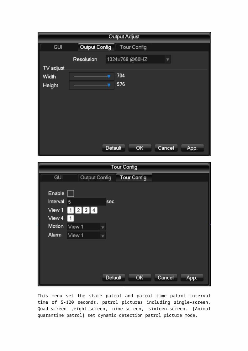
Output configuration[Resolution] Select the output resolution, a total of 1024x768 @ 60Hz, 1280x720 @ 60HZ, 1280x1024 @ 60Hz and 1920x1080 @ 60Hz are four default to 1024x768 @ 60Hz.[TV adjust] adjusting the TV output of the region when the screen cannot be displayed full screen display or displayed on a monitor when the monitor range is exceeded, adjust the images to normal size.
Polling configuration

This menu set the state patrol and patrol time patrol interval time of 5-120 seconds, patrol pictures including single-screen, Quad-screen ,eight-screen, nine-screen, sixteen-screen. [Animal quarantine patrol] set dynamic detection patrol picture mode. [The police patrol] set the alarm patrol picture mode.

Note: the shortcut sets: in the right corner of the monitor screen in real time using the mouse to click the button or press the Shift key, switch may play a role in control of patrol.
4.4.4 Restore the default
[Restore default] It restores system to factory default configuration state (you can choose to restore specific items).
Note: menu colors, language, time, date format, video format, IP address, user accounts will not be restored.
4.4.5 Automatic maintenance
[Maintenance] Set the automatic maintenance projects.
4.4.6 Upgrade the system
Can upgrade the system with USB system upgrade.

4.5 Storage Management
Basic Configuration
Basic configuration interface, as shown in the figure, the display the current embedded DVR hard drive
capacity of the Ministry of remaining capacity, and work status.
[Format] formatting the hard actions, users are required to have the appropriate permissions. Note: the hard drive formatting operation will result in loss of DVR information. [Set] single drive can be set to read-write, read-only, redundant mode. When you need to protect a piece of hard data is overwritten by the cycle, can be set to read-only. Hard disk smart detection of S.M.R.T

Video eventsVideo menu, displaying in native hard disk video start and end times, as shown in the figure:
4.6 Video backup
The video backup operation in video backup menu USB port external storage devices, interface as shown.
[Detection] when you insert a USB external storage device can detect whether the USB device is correctly identified. If identified correctly, the list should be displayed in the corresponding device and the correct capacity. [Backup] tick select the USB external storage device to back up, click the [backup] into the backup interface, interface as shownThe backup operation

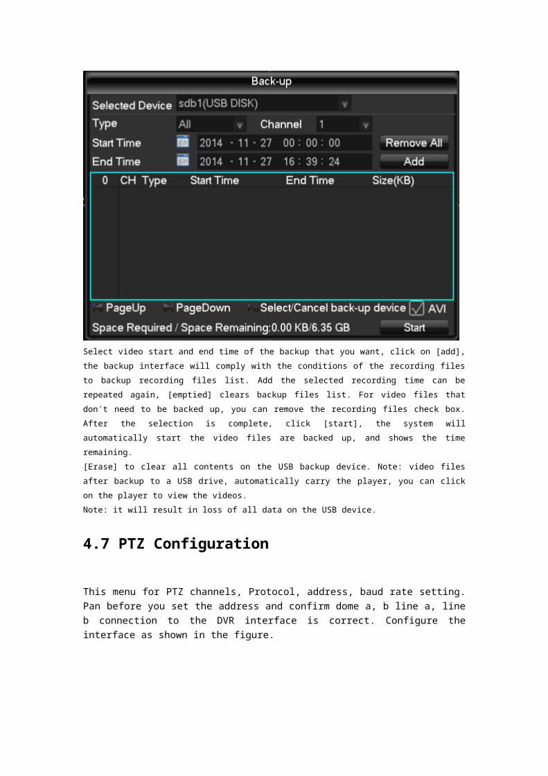
Select video start and end time of the backup that you want, click on [add], the backup interface will
comply with the conditions of the recording files to backup recording files list. Add the selected recording
time can be repeated again, [emptied] clears backup files list. For video files that don't need to be
backed up, you can remove the recording files check box. After the selection is complete, click [start],
the system will automatically start the video files are backed up, and shows the time remaining.
[Erase] to clear all contents on the USB backup device. Note: video files after backup to a USB drive,
automatically carry the player, you can click on the player to view the videos.
Note: it will result in loss of all data on the USB device.
4.7 PTZ Configuration
This menu for PTZ channels, Protocol, address, baud rate setting. Pan before you set the address and confirm dome a, b line a, line b connection to the DVR interface is correct. Configure the interface as shown in the figure.

[Channel] select the channel with PTZ camera access. [Protocol] select brand type of PTZ Protocol (such as PELCOD) [Address] set the appropriate address, default is 1 (Note: here the address be sure to line and dome address, you cannot control the pan/tilt). [Baud rate] select the baud rate used for PTZ, PTZ and camera to the respective channel controls default is 2,400. [Data bits] the default is 8. [Stop bit] the default is 1.[Verify] the default is no.
4.8 Network Configuration
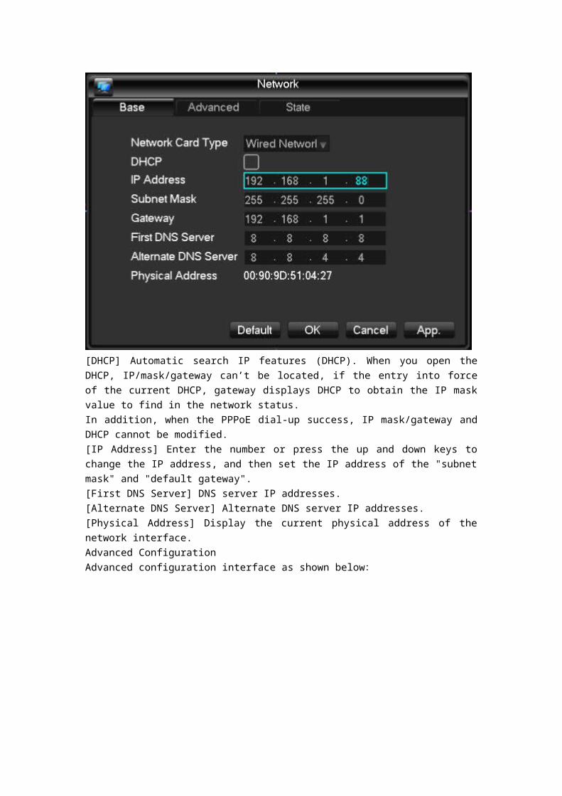
Enter the network configuration interface, DVR network parameters can be set. DVR factory default IP address is 192.168.1.88.Basic ConfigurationThe basic configuration interface as shown below:

[DHCP] Automatic search IP features (DHCP). When you open the DHCP, IP/mask/gateway can’t be located, if the entry into force of the current DHCP, gateway displays DHCP to obtain the IP mask value to find in the network status. In addition, when the PPPoE dial-up success, IP mask/gateway and DHCP cannot be modified.[IP Address] Enter the number or press the up and down keys to change the IP address, and then set the IP address of the "subnet mask" and "default gateway". [First DNS Server] DNS server IP addresses. [Alternate DNS Server] Alternate DNS server IP addresses. [Physical Address] Display the current physical address of the network interface.Advanced ConfigurationAdvanced configuration interface as shown below:

[PPPOE] After selecting so that it can begin to turn the PPPOE dial-up service.
Enter the ISP (Internet service provider) provides a PPPOE user name and password and save.
Operation: after successful PPPOE dial-up, see the [network status] on the IP, get the device's IP
address, enter the IP address and then open IE to access the device.
[DDNS] Adopt the dynamic DNS server. Using this method requires a server with fixed IP addresses
located on the Internet and in the dynamic DNS server running on the server.
Select the DDNS types (currently supports multiple DDNS in the list, including CN99 DDNS,Dyndns DDNS,NO-IP DDNS,Oray DDNS,NETNVR DDNS,DVRIPC CN,DVRIPC NET,and IVS168 DDNS you can simultaneously open multiple DDNS, choosing your own settings) and select Enable,
resolve IP column, enter the DDNS server IP address, and configure the port, domain name, user name,
and password, and then save. When DDNS is configured and running successfully, the domain name
will automatically point to the current public IP address of the device.
Private DDNS function supporting the use of dedicated DDNS server and dedicated client
software.
Detailed configured Please reference 6.1 DDNS function
[NTP] After selecting the Enable switch to turn the NTP protocol support, communication with SNTP
server automatic error correction.
Host IP: enter the NTP server's IP.
Port: the SNTP only supports TCP transport, the port is only limited to 123.
Update cycle: interval time of 1 minutes, maximum update period is set to 65,535 minutes.
Time zone: London GMT+0 Berlin GMT+1 Cairo GMT+3 Delhi GMT+5 Bangkok GMT+7 Hong
Kong/Beijing GMT+8 Tokyo GMT+9 Sydney GMT+10 Hawaii GMT-10 Alaska GMT-9 Pacific time
GMT-8 American mountain time GMT-7 U.S. central Time GMT-6 U.S. Eastern time GMT-5 Atlantic
time GMT-4 Brazil GMT-3 Atlantic-central GMT-2.
[IP Filter] To access the DVR's IP rights management. When selecting white list, the only IP in the list
can be connected to the DVR. It supports 64 IP settings. If the tick is not checked, there are no
restrictions on accessing the device's IP.
[Network transmission capacity , port, UPNP.]
[Network settings]
[Network monitors the number of connections] Connection: 0-10, if you set 0 does not allow
network users to connect, the maximum number of connections to 10.
[Network connections] Connection recommended: 0-8, the required check to start the function.
Same as above
[Network QoS] Fluency takes precedence over the priority or adaptive or quality, depending on the
setting, network auto-tuning stream.
[Network high speed downloading] Network service availability of bandwidth, high speed download
speed is 1.5 times normal download speed ~2 times, the required check to start the function.
[Port settings]
[HTTP port] typically defaults to 80.
[TCP port] typically default to 8,000, ports can be set according to user's actual needs. [Phone
port] typically default to 5,000, ports can be set according to user's actual needs. [UPNP]
Agreement automatically open the port mapping on the router, when you use this feature, ensure
that the UPnP feature is enabled on the router.
Detailed configured Please reference 6.2.1 UPnP function
[Email] sets the sender's mailbox SMTP server's IP address, port, user name, password and sending
mail, mail SSL encryption.
Support English or Arabic input in the message header, maximum 32 characters can be entered.
Maximum 3 receive address and SSL encrypted mailboxes.
[FTP] FTP upload file type video files and pictures both investee sets the FTP server address, port,
remote directory, and so on. Remote directory to empty the capital contribution system automatically by
IP, time, channel, create different folders.
And the user name, password, access FTP user name and password.
Set the upload file length, need to upload the file channel, time, type, and so on.
Set upload length investee and the length of the files uploaded to the FTP server, if is less than the
value, upload the entire video file; if the value is greater than the set, get and set values from the
beginning part of the upload; omitted later in the document, set the value to 0, you upload the entire
video file.
And the different channels can be set 2 different time periods, three types of video recording.
"Alarm Center" reserved interfaces for customer development.
[3G] Support 3G dial-upNetwork StatusDisplay native the DHCP state and PPPOE status and IP.
4.9 Alarm settings
The module includes alarm configuration, abnormal configuration and alarm output.

4.9.1 Alarm configuration
Local alarmLocal the alarm configuration interface as shown:
[Alarm input channel] select the alarm input channel. [Switch] can choose to make opening and closing control alarm input at the beginning. [Device type] Normally open and normally closed type two selection modes. [Copy] T Configuration will be copied to the other channel.[Handling] enters alarm linkage settings click on the interface, the interface as shown in the figure:

[Deployment period] menu displays the deployment time into editing the schedule can be set on the time of day. [Linkage set] by making the switch is turned on [video channel linkage] and [linkage], [patrol] and [shot] linkage, linkage and select channel.
[Approach] By making can switch to select open [alarm output], [ScreenTip], [Send Email] and [beep]. Alarm cancel the delay time can be set to 10-300 seconds.
Video detection
[Dynamic detection] Pairs appear in the image of the movement to be detected, and in accordance with
the configuration of the alarm.
[Locale] shield set a total of 22*18=396 region, set in the region, not for dynamic testing.
[Sensitivity] There are six kinds of the highest, high, medium, low, low and minimum level
[Approach] and local police are the same.
[Start preview] click according to the existing configuration to simulate the alarm hasn't started yet.
[Video loss] for video loss detection, and alarm depending on the configuration.
[Approach] and local police are the same.
[Start preview] click according to the existing configuration to simulate the alarm hasn't started yet.
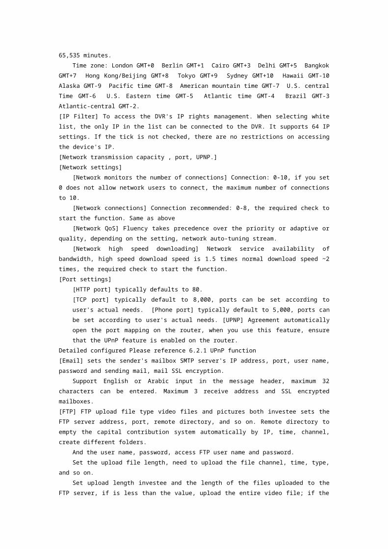
4.9.2 Abnormal configuration
Abnormal configuration interface as shown:
[No hard disk] when there is no hard disk or hard drive will not be recognized by the DVR alarm.
[Approach] Linkage can be set "alarm output", "screen tip" and "send email".
[Insufficient hard disk space] Alarm when the machine's hard disk free space is below the set threshold
(percentage).
[Approach] The same way with no hard drive
[Disconnection event] occurs when the unit is disconnected from the network to police.
[Approach] Linkage can be set "alarm output", "screen tip" and "send email" and "video channel
linkage".

[IP conflict] network IP address conflicts when native police.
[Approach] The same way with no hard drive
[Hard disk error] occurs when the native hard disk read/write errors alert.
[Approach] The same way with no hard drive
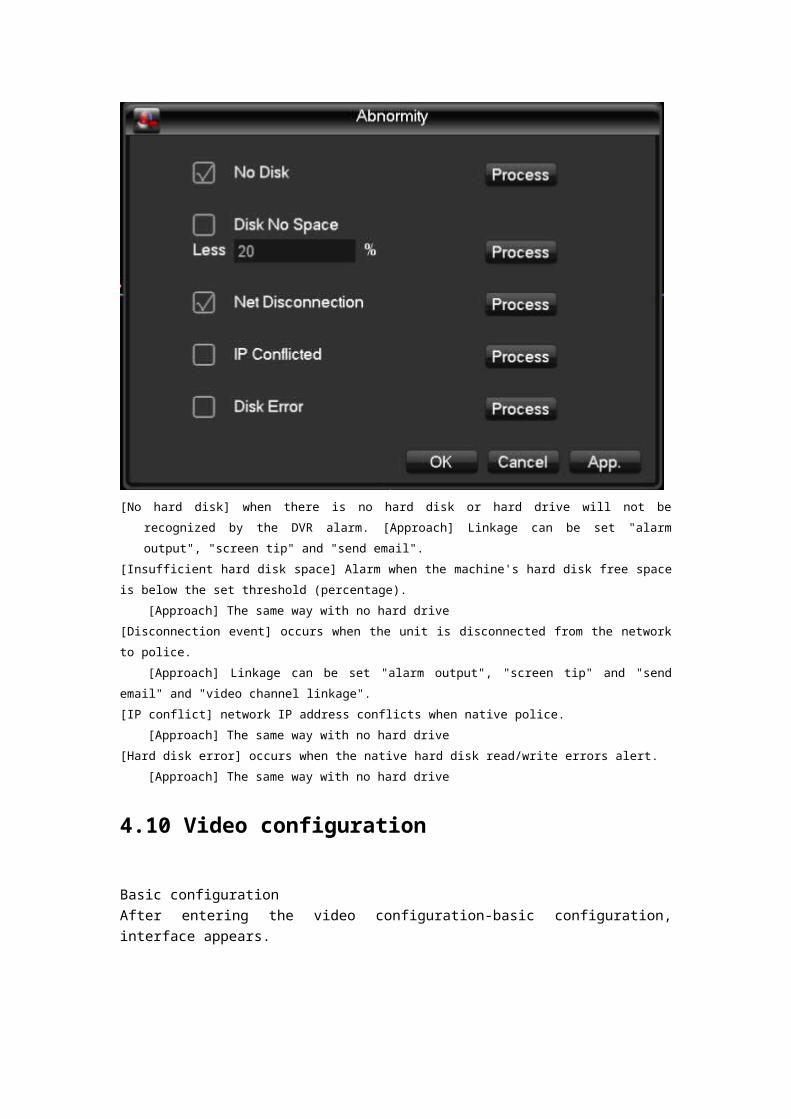
4.10 Video configuration
Basic configurationAfter entering the video configuration-basic configuration, interface appears.
[Channel] select the channel you want to set. [Code mode] select the channel you want to set. [Resolution] The main stream types for resolution 720P optional. Channel, different resolution, frame rate, frame rate that corresponds to the setting that corresponds to the scope is different. Channel expansion resolution can support the CIF/360P. A variety of main stream parameters, users can be combined as needed. [Frame rate]P system: 1 to 25frames/sec; N system: 1-30 frames/second.Note: the main stream resolution and frame rate, subject to different types of equipment and process version limit. [Stream control] includes qualified stream, variable bit-stream. Qualifier code shed encoding bit-rate can be set; variable bit-shed quality to choose quality provided 6, respectively, for the low, low, low, medium, high and maximum. [Audio] select the primary stream/extended opening and closing States of streaming audio encoding.

[Shot] click capture settings, you can set the capture mode, the picture size, picture quality, capture frequencies.
[Capture modes] trigger shot, when used with alarm, alarm picture crawl settings. [Picture size] select the CIF resolution shots. [Picture quality] 6-speed can be set, respectively, for the low, low, low, medium, high and
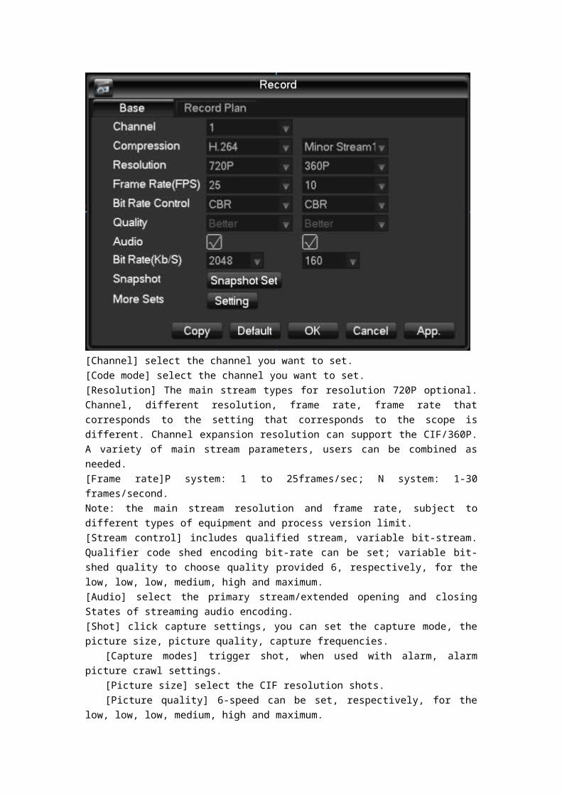
maximum. [Capture rate] setting the single-channel maximum shot frequency, respectively is 1 second /
2, 1 second, 2 second, 3 seconds, 4 seconds per picture, 5/6 seconds//sheets/, 7 seconds, 8 seconds; [Additional configurations] click [settings] to enter the Setup menu.
[Displays the channel name] checkbox on the screen displays the channel name.[Display date] check whether the current time is displayed on the screen. [Channel title] click to access, you can drag any channel position of the title, even if you save, right-after the exit, in which case the channel where the title is changed on the monitor or the monitor will not change in the video and on the WEB interface displays the modified position. [Time title] after click here to enter, free to drag the time position of the title, even if you save, right-after the exit, in which case the time where the title is changed on the monitor or the monitor will not change in the video and on the WEB interface displays the modified position. [Privacy] you can preview and monitor up to 4 privacy protection regional settings, adjustable shield area of arbitrary.
[Preview] setting in the preview screen, real-time monitoring of the State, the shield region on the screen, but in networks and video files, shielded area does not exist.
[Copy] Configuration will be copied to the other channel.Video plans

[Channel] select the channel number. The menu will with green, yellow, red three kinds of color display
the corresponding channel a week ordinary, dynamic detection and alarm three video state of time plan,
can be in click on each date corresponding [configuration]modified.
[Copy] Configuration will be copied to the other channel.
Click on [configuration] to enter the editing interface as shown below:
[Time period] set recording time, choice of 6 periods a day.

[Normal] For ordinary video selection is valid. [Dynamic test] Valid selection for dynamic detection of video. [Alarm] After selecting the alarm linkage recording effective.
5 WEB and client
5.1 WEB operation
5.1.1 Network connection
Confirm that your hard disk video recorder correctly plugged into the network, 7,000 series can via the front panel LCD to check network connection status, if the network status icons are displayed as "XX", means that the network connection error, And 8,000 series via the front panel b light enables you to view the network connection status, if b is lit, it means that the network connection, contrary, network is not connected.
To the mainframe computer and DVR set IP address, subnet mask, and gateway. If no routing device on your network, please allocate the same IP address of a network segment, if the routing device on your network, you need to set up the gateway and subnet mask. DVR’s network setting, see [configuration management]-> [network configuration].
Make sure to set the correct IP address. IP address after Setup is complete you can use the Ping tool to check for system comes with DVR is properly connected to the network.
5.1.2 Control installation and user login logout
When properly connected to the network DVR, DVR can be accessed through IE browser login. Enter the DVR IP address in the IE browser, connection successfully ejected the following interface:
The browser prompts to install the ActiveX control, please left keys to select to Allow the control. If the system is blocked from being downloaded, set the DVR IP address to the trusted sites or lowering the browser security level setting.
Controls after the installation is complete, please enter a username in the login bar, confirm the password, and click Login. After successful login, the browser interface as shown.Finished click on the "exit" sign.
5.1.3 WEB operator interface
Number 1 Channel selection window Select channel video monitoring window displays.Number 2 Function keys Local Playback can choose a local video file playback, All open all channels of real-time monitoring of video monitoring window open at the same time.Number 3 Video surveillance window Display real-time video or playback videoNumber 4 Image color and other settings Image Color can adjust the video brightness, contrast saturation. Other settings can be set to capture saving path, video download path to save and reboot DVR.Number 5 PTZ control PTZ control menuNumber 6 System Menu System configuration, video search, alarm settings , about to exit the function keys .
5.1.4 Real - time video surveillance
After entering the WEB interface, select a video in the monitor window the focus window, the focus window light blue border appears. Available through the channel bar to the left of the interface, select open corresponding live video channel, as shown in the figure.
Hit area 2 you can choose to turn on/off the main stream channel or secondary stream. Video surveillance’s the upper-right corner of the window, as shown in the figure, showing the current DVR's IP information and current rate information.
The lower left corner of the video window to display the current title name of the video information.The upper right corner of the video window to display the current time of the video information.The lower left corner of the video monitor window switch cloud, by clicking
, Can switch the video window screen single screen, multi-screen mode.Video surveillance capabilities pad on the right corner of the window, as shown in the figure, which correspond to regional switching amplification, single image, multiple images, local video,
capture, mute control functions.
Partial enlarged:Partial enlarged on the video monitor screen.
Single-screen, multi- screen switching:Direct single - screen mode and multi- screen mode to switch control of the video window.
Local video :Synchronous saved locally on your computer in real-time monitoring, while a video recording, video path configured in other settings.
Capture : Current channel video capture pictures in other settings default save path configuration.
Mute Control:Can be opened or turn off the audio.
Close video:Close focus window video.
5.1.5 PTZ control
Before using the pan/tilt console, users must first set up PTZ Protocol (see "peripheral configuration"-> "PTZ configuration"), you cannot pan/tilt control operations. PTZ direction, step size, zoom, focus, Iris, preset points, cruising, linear sweep boundary between points, lights, wipers, horizontal rotation control. Step is mainly used for operations, such as step 8 of the rotation speed of the rotation speed is much larger than the step size to 1. PTZ support 8 direction of rotation, respectively, on the top, bottom, left, right, left, right, down, left, down, right.

Linear sweepAction: through the arrow buttons to select the camera left boundary line scan, and click to set the left border button to determine the position of the left border. Through the direction buttons to select the camera to the right edge of line scan, position and click on the settings button on the right the right edge, complete the set of line sweep of the road.
Preset pointAction: through the direction button to turn the camera to the desired position, preset point enter the preset values in the input box, click on the Add button to save.
Cruise groupOperations: cruise line value entered in the input box. Preset point enter preset point value in the input box, click on the Add button, which is cruising at that point were added to the group a preset point. Multiple operations increased more than a preset point. Or click on the delete button, you can delete the presets the cruise route between points. Also multiple operations to remove more than one already exists in the cruise set preset point between points.
ScanAction: record the process of patrol tracks x, click on the Start button, and then return to the PTZ control menus, gathered after a series of operations, such as orientation, Aperture, or go back to the patrol track settings menu, click on the stop button. Complete the Setup on a patrol track route.
Aid

Select a secondary item, click Start or Stop button.
WipersPTZ protocol with lights wipers premise can be turned on lights wipers on and off control.
5.1.6 System Configuration
Click on the [system configuration] can access DVR configure local management of the configuration menu, as shown in the figure. Detailed configuration methods, refer to 4 local operations guide.
5.1.7 Video inquiry
Click on the [video query] to enter video Query menu, as shown in the figure, and recording, alarm, motion detection, local video queries and operations.Video inquiryBy selecting the video type, start and end time and click on the query button, you can get the list of files on the DVR. Select the file to play and download.Broadcast

Double-click documents obtained by a query or click on the play button, you can play a video file in the video window. At this point, below the video window displays the video control buttons, you can control during video playback.
Download: select query access to the file and click on the download button, you can download the files on the DVR to computer local. Download process where the bottom of the query interface displays the current download speed and progress.
5.1.8 Alarm settings
Click on the [set alarm] to enter alarm Setup menu, you can set how the WEB tips-end alarm and operation, as shown in the figure.If you need real-time and displays an alert message pops up in the WEB interface, open the [monitor alarm], and select the appropriate type of alert. And the alarm type by selecting the menu on the left, for video loss, dynamic testing, the hard disk is full, hard drive failure, video block, real-time encoder alarm, external alarm monitoring.

You can choose "open video" enabled, missing the opening video, dynamic testing, the hard disk is full, hard drive failure, encoder alarm joint video, video block pop-up feature. You can choose [prompt] enabled, turn on hint feature: real time alarm settings window menu pops up when an alarm occurs.By [play alarm sound], select an alert play a pre-recorded alert local hard disk when the alarm tone, tone should be in WAV format.
5.1.9 About
Please view the WEB control version information.
5.2 Client operating
Reference 《IMS200 manual》

6 Extended functionality
6.1 DDNS function
6.1.1 Outline
Dynamic DNS is a system with variable IP address Internet domain names point to. Make rules under Internet domain name, the domain name must follow a fixed IP address. Dynamic DNS system provides a fixed dynamic Domain Name Server, and then through the boot Name Server to query for a domain name to dynamic IP addresses of users, allowing outside users to connect the dynamic user's Web site.
6.1.2 VSSIP
VSSIP is our built-in DVR dynamic DNS service, please contact the Distributor or agent for dynamic DNS account. Once you have your account open in the configuration page, and fill in your account information, you can use.
6.1.3 3322 DDNS
RegisterRegister a new user or login in http://www.3322.orgClick on the navigation bars [my console] Click left, dynamic domain name the following [new] Fill in the host name, their name, IP address automatically detect current network public IP, mail servers do not fill, and then click "OK". Embedded DVR side configurationOpen the embedded DVR main menu -> [Configuration Management] -> [Network Configuration] - > [Advanced Configuration] -> [DDNS] enabled:
DDNS Type CN99 DDNSHost IP Members 3322.orgPort 80Domain name xxx.3322.org(xxx: Created domain name)

User name xxx(Account of the application)Password xxxxxx(When applying for password)
After a successful Internet access settings to access DVR through XXX.3322.org. Description: website of the host IP information shall prevail!
6.1.4 NO-IP(www.no-ip.com)RegisterRegister a new user name in the no-IP, click on the [Create Account].Create a domain name, click on the [Add a Host]Embedded DVR side configurationOpen the DVR port configuration [main menu]->[configuration management]->[network configuration]->[Advanced Configuration]->[DDNS];
DDNS Type NO-IP DDNSHost IP dymupdate.no-ip.comPort 80Domain name xxx.xxx.org(xxx: Created domain name)User name xxx(Account of the application)password xxxxxx(When applying for password)
6.1.5 Dyndns DDNS(www.dyndns.com)
RegisterLogin Dyndns official website and registered account.When you click on the mailbox to confirm a link, login accounts, [My Services] click "Add Host Services", set up your own domain name, and then follow the steps to enter.Embedded DVR side configurationOpen the DVR port configuration [main menu]->[configuration management]->[network configuration]->[Advanced Configuration]->[DDNS];
DDNS Type Dyndns DDNSHost IP Members dyndns.orgPort 80Domain name xxx.xxx.org(xxx: Created domain name)User name xxx(Account of the application)password xxxxxx(When applying for password)

6.1.6 Dynamic DNS verification
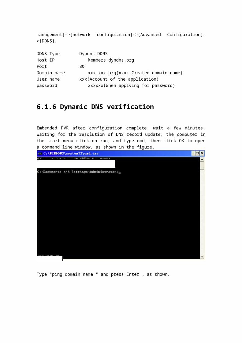
Embedded DVR after configuration complete, wait a few minutes, waiting for the resolution of DNS record update, the computer in the start menu click on run, and type cmd, then click OK to open a command line window, as shown in the figure.
Type "ping domain name " and press Enter , as shown.

Computer from the DVR is configured to resolve domain name, and returns the domain name is currently pointing to IP, as marked by the red line in above image. If the IP matches the public IP of the DVR's network, the DDNS is configured successfully. Do not match, please check your network connections and DDNS configuration DVR information is wrong.
6.2 Port mapping
Port mapping is outside the network IP address of the host map a port to a machine in the network and provide the corresponding service. When a user accesses the IP port, automatically maps the request to the server on the internal LAN machines. Use port mapping feature can be more than one network machine IP address port mapping to network different ports on different machines. Port mapping feature you can also complete some specific agent functionality, such as agent POP, SMTP, TELNET agreement. Can theoretically provide more than 60,000 ports mapped.
For example:To map a WEB server with IP address 192.168.111.10, just 192.168.111.10 and the IP address of the server TCP port 80 to provide Web services to go into the router's port mapping table. Implement port mapping includes two methods: UPnP feature to automatically map and manually modify the router port mappings table.
6.2.1 UPnP function
In order to achieve through the public network access installed on the LAN-internal DVR devices,

we need to configure the router, the NAT implementation DVR through. UPnP function is possible by embedded DVR with built-in automatic NAT Upnp Protocol through, without having to configure the router. Note: the router support needed to implement Upnp functionality and open Upnp functionality.
The first step:The router plugged into the network, enter the menu of the router control, configuration, and then enter the port forwarding, UPnP feature turned on. Router functions from different manufacturers vary, please read before configuring the router's manual.
The second step:Connect the DVR to a router, configuring automatic IP or static IP. Complete the IP configuration, when you enter the "Advanced Configuration" in the "network transmission capacity, ports, multicast, and so" options open "UPnP port mapping". DVR default access ports including HTTP port 80 and TCP port 8,000, if the port is already occupied by other devices in the LAN, then "network transmission capacity, ports, multicast," modify the default port on the DVR to ports that are not occupied.
The third step:Enter the router administration interface, inspection in port forwarding is automatically adding DVR port mapping rules. If so, the Upnp function is configured successfully.The fourth step: enter the public IP address in the IE browser, and after the IP port number Plus DVR you want to access, such as 155.157.12.227:81. Accessed through the client software, if used outside the network TCP ports that are configured Note: If more than one DVR set UPnP function is done by each setting DVR port to a different port number to avoid conflict, or to priority ports DVR set for first choice
6.2.2 Manual port mapping
The first step:Connect the DVR to a router, static IP configuration, complete IP configuration.
The second step:Login the router, enter the router configuration, configuration, and then enter the port forwarding, set the IP address assigned to the DVR, and set a port mapping rule, need to DVR the HTTP, TCP ports are added to the mapping table.DVR default access ports including 8,000 HTTP port 80 and TCP port, if the port is already occupied by other devices in the LAN, then "network transmission capacity, ports, multicast," modify the default port on the DVR to ports that are not occupied.The third step:In the IE browser, enter the public IP address and IP with embedded DVR you want to access the
port, such as:http://155.157.12.227:81。If accessed through the client software, used outside the network TCP ports that are configured.

Note: The detailed configurations please refer to the instructions provided by the manufacturer of the router.
6.3 NTP function
Start the NTP feature implementation DVR automatic clock synchronization with time server in order to ensure the accuracy of the device time.
6.3.1 Internet network environment settings
Enter [configuration management]->[network configuration]-> [Advanced Configuration]-> [NTP settings] settings. When the device can access the Internet network, NTP server directly using standard NTP server on the Internet network as the clock source, such as the China National Time Service Center server (IP address 210.72.145.44) . In NTP settings directly fill in the IP address or domain name of the corresponding server address. Start the NTP, makes you want to check. School time every 1-65,535 minutes you can set.
6.3.2 Private network environment settings
If DVR use environment for private network, you can set up private NTP server in the network as a clock source for DVR.Embedded DVR fill configured NTP server addresses in the private address of the NTP server. Private NTP servers can use standard NTP server products, or PC system time accurate. If you use PC systems as NTP server may refer to the following method:The NTP service erecting of Windows systemIn the start" menu->"running" (or Win+R type "regedit") into the registry editor. HKEY_LOCAL_MACHINE\SYSTEM\CurrentControlSet\Services\W32Time\Parameters creates a new “DWORD Value” key value under the registry subkey:The key to 1 and save:Restart the computer.
The NTP server erection of the Linux systemDue to the special nature of the Linux system, detailed erection NTP service , please refer to the description of each release .

6.3.3 P2P cloud service
Mobile ( Tablet ) Software InstallationUsers with android Mobile or android Tablet can scan QR code “ Android Device Downloading address “ to get accurate link downloading android app called N-eye or search and install it from Android market .Users with I-phone mobile or Tablet an scan QR code “ IOS Device Downloading address “ to get accurate link downloading android app called N-eye or search and install it from Android market .
Android Device Downloading address IOS Device Downloading address
Remote viewing via Mobile or Tablet Firstly, open and run N_eye , click “ +” / Add, then you will have three different type to add device ID.
1、Choose QR Code scanning from machine or packed box to get ID, then add it on Mobile.2、Choose Manual Input , you must input the device ID.3、Keep Device at same LAN IP with mobile phone or Tablet , then choose “ LAN Searching “, you will get its ID,too .
When finish ID adding,please click “ Confirm”, then you can view real-time video of the device .
WAN Remote Viewing with PCOpen www.yunyis.com , then skip to Management Page to choose
“Device Login “
Input device ID, choose channels and checking code, click “Device Login “ will help you remote-viewing the realtime video of the device.
6.4 PTZ function
Under the monitor screen in real time, to control channel of the picture click the right mouse button and select "PTZ" to enter PTZ control interface.
Click brings up the PTZ control menus are available for PTZ camera, direction, step size, zoom, clustered controls, and access advanced features, accessibility, camera settings interface for operation.
General operation: (same step, but the distance is not equal) Step: mainly used to control the direction of operations, such as step 8 of the rotation speed of the rotation speed is much larger than the step size to 1. (Their values can click Digital soft Panel or directly press the 1-8 front panel step, 8 is the maximum step size). Click directly on the camera, zoom, gathering minus, plus key, to adjust the zoom, sharpness, brightness.PTZ support 8 direction of rotation (The front panel can only be used up, down, left and right 4 directions). Fast orientation: in the middle of the direction <SIT>is a quick navigation keys, only supports the
Protocol can only be used for the feature, and can only be controlled with the mouse. Click after to locate pages quickly.
On the page, click “-“ ,PTZ will go to the point and the point to the middle of the screen. Locate pages quickly using the mouse drag. Drag the Zoom box support 4-16 times a function
key, if you want to big screen, press and hold the mouse to drag the upper left corner, if you want smaller screen, press and hold the mouse dragging from right corner to the upper-left corner. Drag
boxes small multiples of bigger and bigger, on the contrary, smaller.
Advanced FeaturesClick on switch into the advanced features menu, as shown in the figure.[Preset] called: preset value in the input box enter the desired preset point of call (previously set preset point) and click on the [preset] button calls.[Cruising] called: cruising between the point value of cruise line value entered in the input box and click the [cruise] button, you can call, click on the [stop] button to stop.[The patrol track] called: patrol tracks cruise line value entered in the input box and click the [cruise] button to make the call. Camera automatically set reciprocating keeps track of movement, you can right-click the menu hidden. To enter the menu press any key to stop the patrol track runs manually.[Linear sweep] called: to enter the menu, click the line scan button, start the line according to the previous set line-scan-scan operation, while [line scan] button changes to [stop] button, you can right-click the menu hidden, to stop the line scan, click the [stop] button.
Auxiliary functionsClick on the [switch the page] to access the settings accessibility (accessibility option corresponds to the protocol used), as shown in the figure. Auxiliary switch on the secondary number corresponds to the decoder.
PTZ settings
Click PTZ control in the menu [settings] button to enter the PTZ settings interface as shown in the figure, set [preset], [cruising],[patrol track], [line-scan boundary]. When you do not support certain features, menu is shaded and cannot be selected.
[Preset] settings: see picture preset point setting, through direction button to turn the camera to the desired position, and then click on the [preset]button in the preset input box, enter the preset point values, click on the [settings] button to save.[Cruising] settings: click on [cruise] button, as shown in the figure, the cruise line cruise line value entered in the input box. Preset point enter preset point value in the input box, click on [increase the preset] button is added to the route of the cruise with a preset point. Multiple operations increased more than a preset point. Or click on the [clear preset] button to delete the preset point in the route of the cruise. Also multiple operations to remove more than one already exists in the cruise line's preset point (delete preset point function of some agreements do not support).

[Patrol traces] of set: click [patrol traces]button, as figure by shows, and will this a process records of for patrol traces x, again click [began] button, then returned to cloud Taiwan control menu for [variable times], and [gathered], and [Aperture] or direction, series of operation, again returned to Xia figure by shows menu, click [end] button.
[Line-scan boundary] settings: click on the [line-scan boundary], as shown in the figure, by choosing a camera left boundary line scan direction, and tap into the menu, as shown in the following figure [left edge] button, and then through the direction buttons to select the camera to the right edge of line scan, and click on the [right] button, complete the set of line sweep of the road.

6.5 Voice intercom
6.5.1 Outline
DVR’s talking, is through local DVR audio input and output, with remote clients or WEB-side talk. Remote client or WEB end voice intercom, embedded DVR local interface audio output through the audio output.Different types of DVR use two types of channel and separate channels, specific information, please refer to the appropriate product specification sheet.
6.5.2 Configuration method
Embedded DVR local configurationMicrophone MIC on the access to an embedded DVR audio input port, audio output to speakers and other output devices: DVR no separate MIC audio input connector, then connect the microphones to the audio input port 1. Note: local output audio output device you want.
Remote PC configurationMicrophone and speakers, access the appropriate computer interface
UseWhen using voice intercom, open the remote client or WEB server, click the voice intercom to voice intercom.

6.6 Hard disk redundancy
Hard drive redundancy feature provides backup for the video data, once after the hard drive is damaged, can through redundant data to retrieve video data, ensure data security, improve the security of the system.
The functionality of the product hard disk redundancy is achieved by specifying channel dual redundant hard disk data backup, which requires a separate hard disk for redundancy.
Hard redundant setLogin DVR main menu, enter [storage management], select as a redundant hard drive that you want, click on [settings], set the hard drive to a redundant disk. Redundancy must be independent of the hard disk, how hard can be high for a group of redundant hard drives. If the hard disk is set to redundant hard drives, video data is saved in normal read and write at the same time, will be recorded in redundant hard drives simultaneously. Redundant video data on your hard disk will automatically
Cycle coverage, cycle depends on the video data and redundant hard drives (disk group) size.
Note: is premised on the DVR set redundant disk has at least 2 drives, one to read and write, the other are used for redundancy.
Channel redundancy settingsThis product can be selected as needed some redundant backup channel or all channel, go to [configuration management] -> [video configuration], select require redundant backup channel, in the [redundancy] box checked. Note: does not turn on redundant data will only be recorded in hard disk to read and write properly, without being a backup redundant disk.
Hard redundant retrieval ofWhen read and write disk is damaged, the video data is lost, you can access to backup video data from a redundant disk. Need to remove the damaged hard disk after the first shutdown, and then power the system back into the "main menu"-"storage management", redundant disk set to read/write disk. Query and playback video playback of the corresponding channel.
6.7 Hard S.MA.R.T technology
SMART's called the "Self-Monitoring Analysis and Reporting Technology", that " self-monitoring , analysis , and reporting technology 。 Support HDD S.M.A.R.T technology available through hard disk monitoring on instruction and monitoring software on the host running heads, platters, motors, circuits, historical records and preset security analysis, comparing the

values. When there is a safety value outside the range, it will automatically warn the user. Seagate hard drive S.M.A.R.T test parameters, for example, specific analysis of main parameters mean. S.M.A.R.T test parameters are divided into 7 columns, namely ID detection code, property descriptions, threshold value, property value, the maximum error value, actual value, and property status.
1. ID detection codeID detection code is not the only, vendors as needed, using different ID code or how much increase or decrease depending on the detecting parameter ID code number. For example, Western Digital's product ID code to "04", test parameter is Start/Stop Count (number of power), while Fujitsu companies the same code parameters for "Number of times the spindle motor is activated" (motor activation time).
2. Attribute nameProperty name that describes the test items, can be customized by the manufacturer increase or decrease, since ATA standards are constantly updated, and sometimes different models of the same brand products will vary. But several major provisions must ensure that the S.M.A.R.T test items (although different manufacturers for test items have specific naming conventions, but the essence of these monitoring projects are the same).
1. Read Error Rate 2. Spin up Time 4. Start/Stop Count 5. Relocated Sector Count 6. Seek Error Rate 7. Power-on Hours Count 10. Spin up Retry Count 194 Power temperature 195 ECC on the Fly count 197 Current Pending Sector Count 198 Off-line Scan Incorrect Sector Count 199 Ultra ATA CRC Error Rate Ultra DMA 200 Write Error Count
Note: different manufacturers, different types of product attributes is not the same. To the user, without an in-depth understanding of their specific meaning, just understand the meaning of monitoring value of the property.
3、ThresholdIt is also known as the threshold value. Reliable property value is specified by the hard drive manufacturer, by a specific formula. If you have a property corresponding to the value of public expenditure threshold, it means that the hard drive will become less reliable, saved in the hard disk of the database can be easily lost. Reliable property values differ from the composition and size of the hard drive, there is a difference. Here it is important to note, some S.M.A.R.T ATA standards only in parameters, it does not provide for specific values, "Threshold" value is set by the manufacturer according to the product characteristics and, therefore, by manufacturers themselves provide detection under Windows with software testing software (such as AIDA32) test results have greater

access.
4、valueProperty value refers to the maximum normal hard drive is factory preset, general scope of 1-253. Typically, the biggest property value is equal to 100 (applies to IBM, quantum, Fujitsu) or 253 (applies to Samsung). Of course, there are exceptions, such as some models of hard disk from Western Digital company production, using two different property values, when production property value is set to 200, but later manufacturing hard property value to 100.
5、WorstWorst is the largest non-hard drive running in the new year there have been normal. It is a calculated value of the Trojan runs on the hard drive, the operating cycle, a number that is constantly refreshed. And very close to the threshold value. S.M.A.R.T analysis and determine whether the status of the hard disk correctly, are the results based on the comparison of this value and the threshold value may be. New maximum property value at the beginning of the hard disk, but with daily use or if an error occurs, the value will decrease and, therefore, larger property values means that hard drives better quality and high reliability, and lower property values the mean likelihood of failure.
6、Raw ValueIt is the actual value, a lot of projects in the various test items to run in hard cumulative value.
7、StatusThis is the S.M.A.R.T property value analysis for front, hard disk provided by the current state of the property, our intuitive judgments hard drive "health" status of important information. Under the terms of S.M.A.R.T, such status is generally OK, warning, and reporting failures or errors, 3 States, S.M.A.R.T found out that 3 status and S.M.A.R.T Pre-failure/advisort BIT parameter assignments are closely related.
7 Appendix
7.1 Term
Dual-streamDual-stream all the way to high-bit-rate stream the local HD storage,
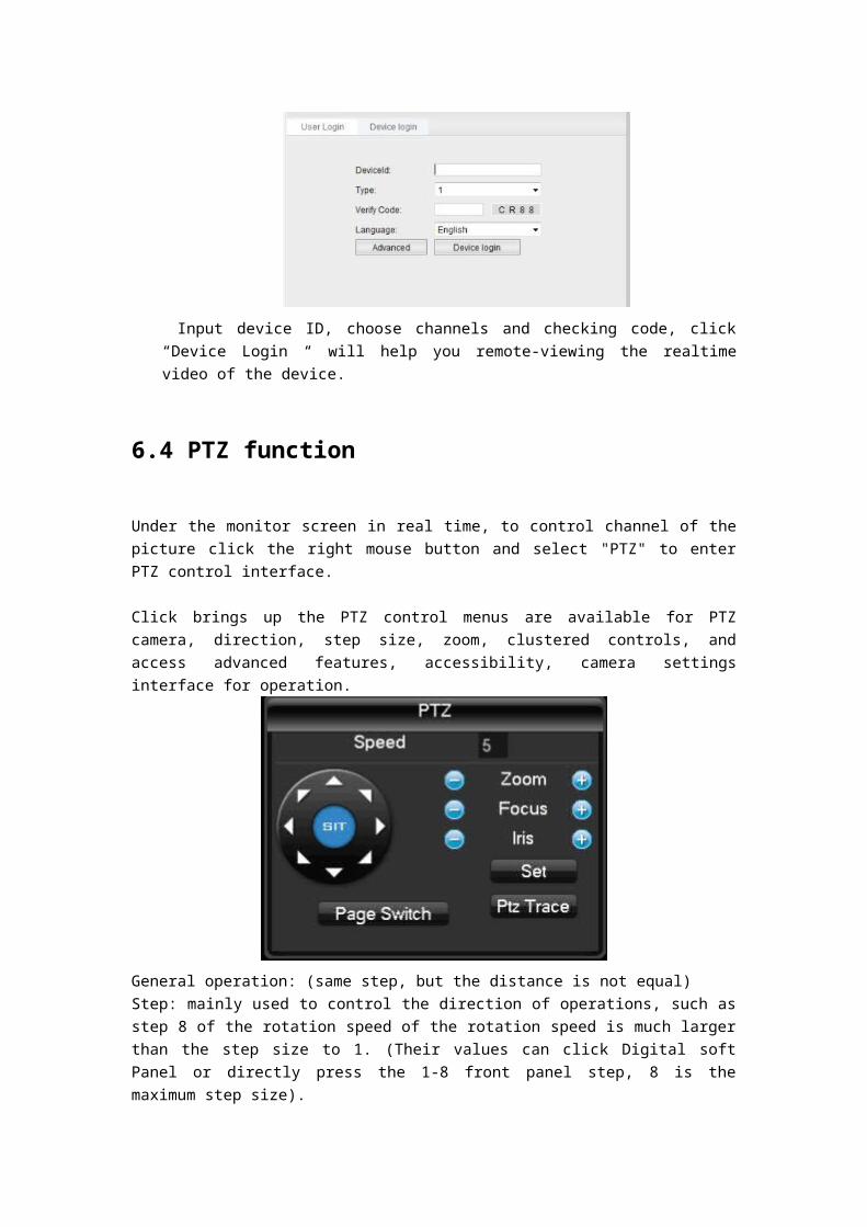
QCIF/CIF/2CIF/DCIF/4CIF, coding, all the way to low bit rate streams for network transmission, such as QCIF / CIF encoding, both local storage and remote network transmission. Dual-stream to achieve local transmission and remote transmission of two different bandwidth streaming needs, local transport with high stream can get more HD video storage, lower long distance transmission stream to accommodate various networks such as CDMA/ADSL for more images and fluid motion.
7.1.1 I-frames
I-frames: Removal of redundant information of image space it is possible to compress the transferred amount of data encoded within the frame of the image, also called a key frame.
7.1.2 B-frames
B-frames: It takes into account earlier in the source image sequence coding frames, taking into account the time sequence between the encoded frame behind the source image redundant information to image compression and transmission of data encoding, also known as bi-directional predicted frames.
7.1.3 P-frames
P-frames: It is through the full will be lower than previously encoded frame image sequences is redundant information to image compression and transmission of data encoding, also known as predictive frames. Wide dynamic range: special lights in the scene special dark parts of the site and at the same time can be seen especially clearly. Wide dynamic range image to distinguish brightness of the brightest signal values and are able to distinguish between the ratio of the value of the darkest light signal.
7.1.4 S.M.A.R.T technology
S.M.A.R.T ( Self - Monitoring, Analysis and Reporting Technology ) :This is now common practice of hard disk data safety technology, working in hard disk monitoring system for motor, circuit analysis, disk, head of State, when an exception is thrown when a warning is issued, it also automatically spin down and back up the data.

7.1.5 VCBS
Kind of analog video signal, it is the composite baseband signal from the luminance and color signals
7.1.6 BNC
A coaxial cable connector, the transmission of the composite video signal or an audio signal lights commonly used for 75 - ohm connector .BNC head welding should pay special attention to the welding strength and remove burrs or signal line contact with the shielding will cause significant attenuation of signal strength.
7.2 Hard disk calculated and maintenance
7.2.1 Hard disk capacity is calculated with reference to
Initial setup of DVR, please make sure the hard drive is mounted in the machine. The size of the hard disk itself.Video recorder there is no limit for a single hard disk capacity, selected based on video saves time.
Choose the size of the total capacity. Hard drive capacity is calculated as:
Total hard disk capacity (MB) = channel number X needs time (hours) X per hour, take up hard disk space (MB / hour)Note: the market to buy the hard drive capacity , 1GB = 1000MB , rather than theoretical 1GB = 1024MB , therefore , [ hard ] - " [ the basic configuration ] , the capacity is less than the actual hard drive nominal value .Fixed bit rate encoding mode when the DVR hour generated the File Size valuation following table.
The size of the stream
( Maximum bit rate )
File Size The size of the
stream
File Size The size of the stream
File Size
96k 42M 320K 140M 896K 393M
128K 56M 384K 168M 1.00M 450M
160K 70M 448K 196M 1.25M 562M
192K 84M 512K 225M 1.50M 675M
224K 98M 640K 281M 1.75M 787M
256 112M 768K 337M 2.00M 900M

When the DVR using variable bit rate encoding mode, hour generated file size larger changes, please refer to the actual size of the generated video files.
7.2.2 Common Troubleshooting
Device failed to start or keep rebooting can cause:
1、 DVR upgrade errors caused by system software are corrupted. 2、 DVR boards fault, contact the vendor maintenance. 3、 A hard disk malfunction, replace the hard disk.
PTZ controlPossible causes:
1、 RS-485 interface cable connections are not correct, reverse A\B port. 2、 PTZ decoder types, Protocol, baud rate, address bit is not set correctly. 3、 RS-485 interface cable is not correct, reverse A\B port. 4、 RS-485 interface board bad.
DVR video corruption may cause the preview image: Video input formats do not match, if the camera is NTSC format, DVR use PAL format, preview images take screen appears.
DVR video playback image corruption or not queryPossible causes:
1、 The program reads an error, try to restart the DVR. 2、 Hard disk error occurred because of bad road, clusters of data, check the hard drive, if your hard
disk is damaged, please replace the hard drive.
3、 DVR hardware malfunction, please contact your supplier.
Unable to connect through a network DVR Possible cause:
1、 Please check your network correctly 2、 Please check the physical connection DVR configuration of network parameters.3、 Please check the IP conflict exists in the network.
Download or backup videos not playing properly Possible causes:
1、 It does not have the correct player installed. 2、 Backup USB flash drive or portable hard drive file system error. 3、 Has no installing DX8.1 above graphics accelerator.
Internet Explore Collapse

Possible causes: IE browser crash problems encountered during such visits, close, and in the tool options for the operation in the following figure.