serious incident 29-12-2014 involving bombardier inc. dhc
TRANSCRIPT

Page 1 of 76
FINAL REPORT
Serious incident
29-12-2014
involving
BOMBARDIER INC. DHC-8-202
OY-GRK
Certain report data are generated via the EC common aviation database

Page 2 of 76
FOREWORD
This report reflects the opinion of the Danish Accident Investigation Board regarding the circumstances of the occurrence and its causes and consequences. In accordance with the provisions of the Danish Air Navigation Act and pursuant to Annex 13 of the International Civil Aviation Convention, the investigation is of an exclusively technical and operational nature, and its objective is not the assignment of blame or liability. The investigation was carried out without having necessarily used legal evidence procedures and with no other basic aim than preventing future accidents and serious incidents. Consequently, any use of this report for purposes other than preventing future accidents and serious incidents may lead to erroneous or misleading interpretations. A reprint with source reference may be published without separate permit.

Page 3 of 76
TABLE OF CONTENTS
SYNOPSIS ........................................................................................................................................................ 7
1 FACTUAL INFORMATION ..................................................................................................................... 9
1.1 History of the flight ............................................................................................................................. 9 1.1.1 Flight animation of the final approach and landing ............................................................. 12
1.2 Injuries to persons ............................................................................................................................. 13 1.3 Damage to aircraft ............................................................................................................................. 13 1.4 Other damage .................................................................................................................................... 13 1.5 Personnel information ....................................................................................................................... 13
1.5.1 The commander .................................................................................................................... 13 License and medical certificate............................................................................. 13 1.5.1.1 Operator training (extract) .................................................................................... 13 1.5.1.2 Flying experience at the operator.......................................................................... 14 1.5.1.3 Duty time .............................................................................................................. 14 1.5.1.4
1.5.2 The first officer .................................................................................................................... 15 License and medical certificate............................................................................. 15 1.5.2.1 Operator training (extract) .................................................................................... 15 1.5.2.2 Flying experience at the operator.......................................................................... 16 1.5.2.3 Duty time .............................................................................................................. 16 1.5.2.4
1.5.3 Aerodrome category and flight crew qualification .............................................................. 17 1.5.4 AFIS operator ....................................................................................................................... 17
License and medical certificate............................................................................. 17 1.5.4.1 Duty time .............................................................................................................. 18 1.5.4.2
1.6 Aircraft information .......................................................................................................................... 18 1.6.1 General ................................................................................................................................. 18 1.6.2 Continued airworthiness....................................................................................................... 19
Aircraft latest A and C check ................................................................................ 19 1.6.2.11.6.3 Propeller control ................................................................................................................... 19
Power and condition lever quadrant ..................................................................... 19 1.6.3.1 Propeller blade angles ........................................................................................... 21 1.6.3.2 Beta backup protection ......................................................................................... 21 1.6.3.3
1.6.3.3.1 Beta backup protection - electrical wiring ........................................ 22 Ground beta range ................................................................................................. 23 1.6.3.4
1.6.3.4.1 Ground beta range - electrical wiring ............................................... 23 Beta backup test .................................................................................................... 24 1.6.3.5 Power lever operated micro switch ....................................................................... 24 1.6.3.6
1.6.4 Operator maintenance system records.................................................................................. 25 1.6.5 Operational flight plan ......................................................................................................... 25 1.6.6 Mass and balance ................................................................................................................. 25

Page 4 of 76
1.6.7 Route performance manual (RPM) ...................................................................................... 25 1.6.8 Landing threshold speed (Vref) ........................................................................................... 26
1.7 Meteorological information .............................................................................................................. 26 1.7.1 General ................................................................................................................................. 26
Significant weather charts ..................................................................................... 26 1.7.1.1 Aftercast ................................................................................................................ 26 1.7.1.2
1.7.2 Weather information - flight crew preflight planning .......................................................... 27 BGGH ................................................................................................................... 27 1.7.2.1 BGPT .................................................................................................................... 27 1.7.2.2
1.7.3 METAR ................................................................................................................................ 28 BGGH ................................................................................................................... 28 1.7.3.1 BGPT .................................................................................................................... 28 1.7.3.2
1.7.4 TAF ...................................................................................................................................... 28 BGGH ................................................................................................................... 28 1.7.4.1 BGPT .................................................................................................................... 28 1.7.4.2
1.7.5 Snow warning to airmen (SNOWTAM) .............................................................................. 29 BGGH at 10:00 hours ........................................................................................... 29 1.7.5.1 BGGH at 11:05 hours ........................................................................................... 29 1.7.5.2 BGGH at 13:45 hours ........................................................................................... 29 1.7.5.3
1.8 Aids to navigation ............................................................................................................................. 30 1.8.1 Circling RNAV GNSS - 1 approach .................................................................................... 30 1.8.2 Notice to airmen (NOTAM) - BGGH .................................................................................. 30 1.8.3 Operator’s airport charts (extracts) ...................................................................................... 30
1.9 Communication ................................................................................................................................. 30 1.9.1 General ................................................................................................................................. 30 1.9.2 Air Traffic Service (ATS) voice recording .......................................................................... 30
1.10 Aerodrome information .................................................................................................................... 31 1.10.1 BGGH airport ....................................................................................................................... 31 1.10.2 Airport chart - ICAO ............................................................................................................ 31 1.10.3 Airport winter operations preparedness ............................................................................... 31
Airport winter preparedness equipment ................................................................ 31 1.10.3.1 Snow clearing sweepers ........................................................................................ 32 1.10.3.2 Melting agent and/or sand spreader ...................................................................... 33 1.10.3.3 Car equipped with Tapley-meter .......................................................................... 33 1.10.3.4
1.11 Flight recorders ................................................................................................................................. 34 1.11.1 Solid State Flight Data Recorder (SSFDR) .......................................................................... 34
SSFDR data plots .................................................................................................. 34 1.11.1.11.11.2 Solid State Cockpit Voice Recorder (SSCVR) .................................................................... 34 1.11.3 Flight Management System (FMS) ...................................................................................... 34
1.12 AIB safety investigation ................................................................................................................... 35 1.12.1 Place of serious incident....................................................................................................... 35 1.12.2 Safety investigation .............................................................................................................. 36
Page 5 of 76
Technical investigation ......................................................................................... 36 1.12.2.11.12.2.1.1 The right hand power lever operated micro switch .......................... 36 1.12.2.1.2 Flight Data Monitoring (FDM) ......................................................... 37
Operational investigation ...................................................................................... 37 1.12.2.21.12.2.2.1 Airport winter preparedness equipment............................................ 37 1.12.2.2.2 Clearing of runway snow and ice deposits ....................................... 37 1.12.2.2.3 Runway inspections .......................................................................... 38 1.12.2.2.4 Airport braking action measurement instruction .............................. 40 1.12.2.2.5 Airport personnel employed at BGGH airport ................................. 41 1.12.2.2.6 Supreme authority to close runway and/or airport............................ 41
1.13 Medical and pathological information .............................................................................................. 42 1.14 Fire .................................................................................................................................................... 42 1.15 Survival aspects ................................................................................................................................ 42
1.15.1 Seats and seatbelts ................................................................................................................ 42 1.15.2 Runway excursion ................................................................................................................ 42
1.16 Tests and research ............................................................................................................................. 42 1.17 Organization and management information ...................................................................................... 43
1.17.1 The operator ......................................................................................................................... 43 General .................................................................................................................. 43 1.17.1.1 The operator’s Safety Management System (SMS).............................................. 43 1.17.1.2 Operations Manual ................................................................................................ 43 1.17.1.3
1.17.1.3.1 Operations Manual Part A ................................................................ 43 1.17.1.3.2 Operations Manual Part B ................................................................ 44
1.17.2 Nuuk airport ......................................................................................................................... 44 General .................................................................................................................. 44 1.17.2.1 Nuuk Airport Operations Manual - extracts ......................................................... 44 1.17.2.2
1.17.2.2.1 Snow clearing ................................................................................... 44 1.18 Additional information ...................................................................................................................... 44 1.19 Useful or investigation techniques .................................................................................................... 44
2 ANALYSIS ................................................................................................................................................. 45
2.1 General .............................................................................................................................................. 45 2.2 Pre-flight planning ............................................................................................................................ 45 2.3 SNOWTAM for BGGH .................................................................................................................... 45 2.4 Approach to BGGH .......................................................................................................................... 45
2.4.1 RNAV GNSS - 1 approach followed by a visual approach to runway 23 ........................... 45 2.4.2 Mutual flight information and traffic coordination .............................................................. 46
2.5 Runway excursion ............................................................................................................................. 47 2.5.1 Reported braking action coefficients.................................................................................... 47 2.5.2 The right hand power lever operated micro switch .............................................................. 48 2.5.3 Runway excursion ................................................................................................................ 48
2.6 Runway snow clearing at BGGH ...................................................................................................... 49

Page 6 of 76
3 CONCLUSIONS........................................................................................................................................ 50
3.1 Findings ............................................................................................................................................ 50 3.2 Factors ............................................................................................................................................... 52 3.3 Summary ........................................................................................................................................... 52
4 SAFETY RECOMMENDATIONS ......................................................................................................... 53
4.1 Area of safety focus .......................................................................................................................... 53 4.2 Preventive actions ............................................................................................................................. 53
4.2.1 The operator ......................................................................................................................... 53 Checklist item ....................................................................................................... 53 4.2.1.1 The FDM system .................................................................................................. 53 4.2.1.2
4.2.2 Greenlandic Airports ............................................................................................................ 53
5 APPENDICES ........................................................................................................................................... 54
5.1 Operational flight plan ...................................................................................................................... 55 5.2 Mass and balance .............................................................................................................................. 56 5.3 Significant weather charts ................................................................................................................. 57 5.4 Operator’s airport charts ................................................................................................................... 59 5.5 Snowplan - Aeronautical Information Publication (AIP) Greenland ................................................ 61 5.6 Airport chart - ICAO ......................................................................................................................... 66 5.7 SSFDR approach ............................................................................................................................... 67 5.8 SSFDR Landing ................................................................................................................................ 68 5.9 SSFDR longitudinal controls ............................................................................................................ 69 5.10 SSFDR lateral controls ..................................................................................................................... 70 5.11 SSFDR engines/propellers ................................................................................................................ 71 5.12 Braking action ................................................................................................................................... 72 5.13 Stabilized approach concept.............................................................................................................. 73 5.14 Landing on contaminated or slippery runways ................................................................................. 75 5.15 Airport operations manual - snow clearing (extracts) ....................................................................... 76

Page 7 of 76
FINAL REPORT General File number:
HCLJ510-2014-282
UTC date: 29-12-2014 UTC time: 15:34 Occurrence class: Serious incident Location: Nuuk Airport (BGGH) Injury level: None Aircraft Aircraft registration: OY-GRK Aircraft make/model: BOMBARDIER INC. DHC-8-202 Current flight rules: Instrument Flight Rules (IFR) Operation type: Commercial Air Transport Revenue operations Passenger Flight phase: Landing Aircraft category: Fixed wing Airplane Last departure point: Greenland (Denmark) BGGH (GOH): Nuuk Planned destination: Greenland (Denmark) (BGPT (JFR): Paamiut Aircraft damage: None Engine make/model: PRATT & WHITNEY (CANADA) PW100 FAMILY (123D)
SYNOPSIS
Notification All times in this report are UTC. The Aviation Unit of the Danish Accident Investigation Board (AIB) was notified of the serious incident by the operator on 29-12-2014 at 15:45 hours. The Danish Transport Authority (DTA), the Canadian Transportation Safety Board (TSB), the European Aviation Safety Agency (EASA), the Directorate-General for Mobility and Transport (DG MOVE) and the International Civil Aviation Organization (ICAO) were notified on 29-12-2014. The Canadian TSB appointed an accredited non-traveling representative to the investigation.

Page 8 of 76
Summary Upon landing on runway 23 at Nuuk (BGGH) and shortly after having selected reverse on both engines, the flight crew experienced that the aircraft unexpectedly started to veer to the left. The pilot flying attempted to correct this by deactivating reverse on both engines and by use of the wheel brakes and the nose wheel steering, but the aircraft continued veering towards the left side of the runway. The aircraft ran off the left side of the runway and came to a complete stop in the safety zone. A momentary failure of the right hand power lever micro switch causing a momentary activation of the right hand propeller beta backup protection in combination with a divergence between reported and effective braking action coefficients on runway 23 had a negative effect on the flight crew’s ability to maintain directional control, which resulted in the aircraft running off the side of the runway. Neither passengers nor crew members suffered any injuries. There were no damages to the aircraft. The serious incident occurred in daylight and under visual meteorological conditions (VMC). The safety investigation did not result in recommendations being made.
Page 9 of 76
1 FACTUAL INFORMATION
1.1 History of the flight The serious incident flight was a commercial IFR domestic passenger flight from BGGH to Paamiut (BGPT). Three crew members and five passengers were onboard. There were no remarks to the aircraft pre-flight checks. The aircraft departed BGGH at 14:07 hours. The commander was the pilot flying and the first officer was the pilot monitoring. En route to BGPT, the flight crew got information of low braking action coefficients at BGPT, which precluded a landing. For that reason, the flight crew decided to divert to BGGH. En route to BGGH and before leaving FL 190, Sondrestrom Information (121.300 MHz) informed the flight crew of OY-GRK of one arriving aircraft from Kangerlussuaq (BGSF) to BGGH and one departing aircraft from BGGH to Reykjavik (BIRK). Furthermore, the flight crew got the information that runway 23 was in use at BGGH. When leaving FL 190, the pilot monitoring reported the aircraft to be on course to the waypoint UVIRI (Initial Approach Fix (IAF) for a circling area navigation (RNAV) global navigation satellite system (GNSS) approach) and reported a frequency change to Nuuk Aerodrome Flight Information Service (AFIS) (119.100 MHz). The flight crew planned to do a circling RNAV GNSS - 1 approach followed by a visual approach to runway 23. At BGGH, the flight crew of the departing aircraft from BGGH to BIRK informed their intention to Nuuk AFIS of departing between the arriving aircraft from BGSF and the arriving aircraft from BGPT (OY-GRK). The reason for their intention was a short hold over time following de-icing of the aircraft. On initial radio contact with Nuuk AFIS, the flight crew of OY-GRK got the following information on runway in use, weather and runway conditions:
- Runway in use was 23 - The wind conditions were calm - The visibility was 3000 meters in light snow

Page 10 of 76
- Vertical visibility was 2000 feet - The temperature was -2° Celsius - The dewpoint was -3° Celsius - The QNH was 982 hPa - Transition Level was FL 90 - The runway conditions were reported to be the same (braking action coefficients for
runway 05 (40, 48 and 50 were measured at 13:40 hours)) like when the serious incident flight departed BGGH.
Furthermore, Nuuk AFIS informed the flight crew of OY-GRK of the arriving aircraft from BGSF inbound for landing on runway 23 and forwarded the intention of the departing aircraft from BGGH to BIRK to depart between the arriving aircraft from BGSF and the arriving OY-GRK. When the flight crew of the arriving aircraft from BGSF reported a distance of 24 nautical miles (nm) from BGGH, the flight crew of OY-GRK decided to reduce the airspeed and reported to be 21 nm from BGGH and that they expected to land as number two. Nuuk AFIS informed the flight crew of OY-GRK that the departing aircraft now intended to depart immediately after the aircraft from BGSF had landed. The visibility was reported to be 2500 meters, and the vertical visibility was reported to be 2000 feet. Established on the circling RNAV GNSS - 1 approach and passing the IAF UVIRI, the aircraft descended through 4900 feet, and the computed airspeed (CAS) was presented to be 179 knots. The aircraft passed the Intermediate Approach Fix (IF) GONEN at 3900 feet with a CAS of 177 knots. The departing aircraft from BGGH started to taxi into take off position and intended to depart before the arriving aircraft from BGSF (on an approximately 12 nm final to runway 23). The flight crew of OY-GRK selected the landing gear down and set the flap setting to 15°. Shortly after, the pilot monitoring (OY-GRK) reported the aircraft to be 10 nm from BGGH doing the RNAV GNSS - 1 approach. Nuuk AFIS informed the flight crew of OY-GRK that runway 23 was in use. The aircraft passed the Final Approach Fix (FAF) ELTUX descending through 2400 feet with a CAS of 129 knots. The departing aircraft for BIRK departed on runway 23 at BGGH.

Page 11 of 76
Passing 1000 feet above aerodrome level (AAL), no flight crew call out on stabilized approach was made. When the flight crew of OY-GRK reported passing 5 nm and 1200 feet descending, Nuuk AFIS requested the flight crew of OY-GRK to confirm that their intention still was to circle to runway 23. The flight crew of OY-GRK confirmed. Shortly before arriving at the Missed Approach Point (MAP) ADMIP, the flight crew got visual contact with the terrain. Passing the MAP ADMIP, the pilot flying initiated a left turn towards the NDB GH (314 KHz) continuing on a visual approach. The aircraft circled west of the airport for landing on runway 23. On course towards GH, the flight crew got visual contact with Nuuk city, and the pilot flying initiated a descent to 650 feet. Before landing, the wind conditions were reported to be variable and 2 knots. On downwind to runway 23, the flight crew tried to establish visual contact with the airport environment. On right base to runway 23, the flight crew got visual contact with the airport beacon, then the runway lights and the runway. The autopilot was disengaged, and the flaps were selected to 35°, while the pilot flying initiated a steep right turn in order to establish the aircraft on final to runway 23. Passing 300 feet AAL, the aircraft was in a slight right turn towards the final to runway 23. The CAS was 96 knots. The pilot flying requested information on the present airspeed from the pilot monitoring. The pilot monitoring replied that the aircraft was stabilized. Upon landing on runway 23 and shortly after having selected reverse on both engines, the flight crew experienced that the aircraft started to veer unexpectedly to the left. The pilot flying attempted to correct this by deactivating reverse on both engines and by use of the wheel brakes and the nose wheel steering, but the aircraft continued veering towards the left side of the runway.

Page 12 of 76
The aircraft ran off the left side of the runway and into the safety zone. In the safety zone, the pilot flying deliberately selected reverse on the left engine resulting in a ground loop. The aircraft came to a complete stop in the safety zone. The flight crew observed that there were no visible or noticeable damage to the aircraft and that none of the persons on board had sustained any injuries. On the basis of the sequence of events, the flight crew decided that evacuation of the aircraft was not necessary. The flight crew reported to Nuuk AFIS that during the landing roll, it had been impossible to maintain aircraft directional control, and the flight crew requested an immediate runway inspection. 1.1.1 Flight animation of the final approach and landing Based on recorded and processed flight data and other information, the following flight animation is a computerized approximation, which represents the AIB’s best estimate of the sequence of events. The data source is the Solid State Flight Data Recorder (SSFDR). Due to data interpolation, certain actual SSFDR parameter values may not be presented in this animation. In order to view the flight animation, please make sure that an appropriate internet connection is available. Flight animation of the final approach and landing
Page 13 of 76
1.2 Injuries to persons
Injuries Crew Passengers Others Fatal Serious None 3 5
1.3 Damage to aircraft There was no damage to the aircraft. 1.4 Other damage There were no other damages. 1.5 Personnel information 1.5.1 The commander
License and medical certificate 1.5.1.1 The commander (42 years) was the holder of a valid Danish Airline Transport Pilot License (ATPL (A)). The ATPL contained the following type rating: DHC8/IR. DHC8 is equal to Dash 8. The type rating DHC8/IR was valid until 31-5-2015. The PART-FCL medical certificate class 1 was valid until 26-3-2015.
Operator training (extract) 1.5.1.2
- Crew Resource Management (CRM) in accordance with the DTA was valid until 30-11-2015
- Emergency training was until 30-4-2015 - Contaminated runways training was valid until 30-11-2015 - Cold weather operations training was valid until 30-11-2015 - Dash 8 line check was valid until 30-6-2015 - License Proficiency Check (LPC) was valid until 31-5-2015 - Dash 8 Operator Proficiency Check (OPC) was valid until 31-5-2015

Page 14 of 76
Flying experience at the operator 1.5.1.3 Last 24 hours Last 90 days Total All types (Dash 7/Dash 8) - 145 5663 This type (Dash 8) - 145 1654 Landings this type - 93 -
Duty time 1.5.1.4 Previous seven days
Duty begin Duty end Rest Block time Duty time Flight Duty Period (FDP)
22-12-2014 09:15
22-12-2014 12:26
28:14 1:36 3:11 2:56
23-12-2014 16:40
23-12-2014 23:55 82:50 4:18 7:15 7:00
24-12-2014 12:00 (Standby)
24-1-2014 18:00 1:00
25-12-2014 DAY OFF
26-1-2014 09:00 26-12-2014 18:00 2:30
27-12-2014 10:45 (Airport standby)
27-12-2014 14:30 43:30 3:45
28-12-2014 DAY OFF 29-12-2014 10:00 28-12-2014 15:51 17:39 1:32 5:51 5:36
Cumulative block duty time totals Months (2014)
Hours
January
28:14
February
29:39
March
41:24

Page 15 of 76
April
46:02
May
30:47
June
18:55
July
83:05
August
67:16
September
53:29
October
32:19
November
41:51
TOTAL 505:34 1.5.2 The first officer
License and medical certificate 1.5.2.1 The first officer (35 years) was the holder of a valid Danish Commercial Pilot License (CPL (A)). The CPL contained the following type ratings: MEP (land), SEP (land), and DHC8/IR CO-PILOT ONLY. The type rating DHC8/IR CO-PILOT ONLY was valid until 31-5-2015. The PART-FCL medical certificate class 1 was valid until 19-5-2015.
Operator training (extract) 1.5.2.2
- Crew Resource Management (CRM) in accordance with the DTA was valid until 30-9-2015
- Emergency training was until 31-3-2015 - Contaminated runways training was valid 30-11-2015 - Cold weather operations training was valid until 30-11-2015 - Dash 8 line check was valid until 30-8-2015 - License Proficiency Check (LPC) was valid until 31-5-2015 - Dash 8 Operator Proficiency Check (OPC) was valid until 31-5-2015

Page 16 of 76
Flying experience at the operator 1.5.2.3 Last 24 hours Last 90 days Total All types (Dash 8) - - 881 This type (Dash 8) - - 881 Landings this type - - -
Duty time 1.5.2.4
Duty begin Duty end Rest Block time Duty time Flight Duty Period (FDP)
22-12-2014 09:15
22-12-2014 12:26
28:14 1:36 3:11 2:56
23-12-2014 16:40
23-12-2014 23:55 82:50 4:18 7:15 7:00
24-12-2014 12:00 (Standby)
24-1-2014 18:00 1:00
25-12-2014 DAY OFF
26-1-2014 09:00 26-12-2014 18:00 2:30
27-12-2014 10:45 (Airport standby)
27-12-2014 14:30 43:30 3:45
28-12-2014 DAY OFF 29-12-2014 10:00 28-12-2014 15:51 17:39 1:32 5:51 5:36
Cumulative block duty time totals Months (2014)
Hours
January
26:34
February
38:54
March
22:03
April
33:29

Page 17 of 76
May
45:37
June
31:47
July
33:00
August
69:18
September
32:48
October
47:52
November
33:32
TOTAL 458:59 1.5.3 Aerodrome category and flight crew qualification In accordance with the operator’s Operations Manual (OM) part A (category list) and OM part B (route and aerodrome training and qualifications), BGGH was a category A aerodrome. All the operator’s flight crews were qualified for category A areas through initial training and normal flight operations. 1.5.4 AFIS operator
License and medical certificate 1.5.4.1 The AFIS operator (57 years) was the holder of a valid Danish Flight Information Service Operator License (FIS). The FIS contained the following Air Traffic Management Unit (BGGH) rating: AFI. The AFI was valid until 31-10-2015. The PART-FCL medical certificate class 2 was valid until 7-3-2015.

Page 18 of 76
Duty time 1.5.4.2
Previous seven days:
Duty begin
Duty end
22-12-2014 07:00 22-12-2014 15:00
23-12-2014 11:00
23-12-2014 19:00
24-12-2014 DAY OFF 25-12-2014 11:00 25-12-2014 23:00
26-12-2014 08:00
26-12-2014 16:00
27-12-2014 DAY OFF 28-12-2014 15:00
28-12-2014 23:00
29-12-2014 13:00 29-12-2014 21:00 1.6 Aircraft information 1.6.1 General Registration: OY-GRK Type: Dash 8 Model: 202 Manufacturer: Bombardier Aerospace, Canada Serial number: 498 Year of manufacture: 1997 Engine manufacturer: Pratt & Whitney Canada Inc. Engine type: PW123D Propellers: Hamilton Standard Division, 14F-23 Aircraft total flight hours: 30 823 Aircraft total flight cycles: 44 831

Page 19 of 76
1.6.2 Continued airworthiness The continued airworthiness of the aircraft was verified to be in compliance with the approved maintenance program. The certificate of airworthiness and the airworthiness review certificate were valid.
Aircraft latest A and C check 1.6.2.1 A check The interval was 500 hours. The latest check was performed on 29-10-2014 (30 631 flight hours). C check The interval was 5 000 hours. The latest check was performed on 11-11-2011 (26 692 flight hours). 1.6.3 Propeller control
Power and condition lever quadrant 1.6.3.1

Page 20 of 76
The two power levers control engine speed in the forward power range (prop constant speed governed range) and the propeller blade angle in the beta range. For normal flight operation in the forward power range, propeller blade angle is controlled by a governor in the Propeller Control Unit (PCU), which regulates propeller speed (Np) in response to condition lever settings. As the power levers are retarded towards flight idle (FLT IDLE), with the condition levers set at MAX, the PCU governor reduces blade angle as it attempts to maintain the selected propeller revolutions per minute (rpm). As blade angle reduces to +26 degrees (at a point slightly above FLT IDLE), the power lever acquires direct blade angle control (beta range). At FLT IDLE, the propeller blade angle decreases to +19.0 degrees. From FLT IDLE, the power lever can be moved further aft until a spring detent labeled DISC is reached. Through this range, propeller blade angle decreases from +19.0 degrees to -3.2 degrees (discing). Further aft power lever movement moves the propeller blades into reverse until the power levers reach MAX reverse, where the propeller blade angles are set to -11.5 degrees. While in the reverse power range, the Manual Fuel Control (MFC) and the Electronic Control Unit (ECU) regulates power and propeller speed proportional to the amount of reverse blade angle selected with the power lever. The condition levers located adjacent to the power levers set propeller rpm in the forward thrust range. Each condition lever provides input to the MFC and the Propeller Control Unit (PCU) of the related engine. The condition levers do not regulate the propeller blade angles in the beta range.

Page 21 of 76
Propeller blade angles 1.6.3.2
Beta backup protection 1.6.3.3
Two blue advisory lights are provided in the left glareshield panel to indicate that the propellers are in the ground range of beta operation. The lights are marked PROPELLER GROUND RANGE 1 and 2. Each blue light is illuminated by a low blade angle switch (P1 / P2 shown in the electrical wiring drawing) that is actuated by the blade angle mechanical feedback mechanism. Illumination occurs when the blade angle is decreasing through +16.5 degrees. In the electrical wire drawings, the propeller ground range lights are illuminated by 28V DC (blue lines) via the P1 and/or P2 switches. A beta backup system provides protection against the propeller entering beta ground range unintentionally due to a PCU malfunction (while the power lever is above ground range). The system uses a beta backup signal, supplied by the low blade angle switch (P1 / P2 shown in the electrical wire drawing), which is relayed to the feather solenoid valve via a power lever operated micro switch (S3 / S4 shown in the electrical wire drawing). The micro switch only relays the beta backup signal when the power lever is above the ground range position. In the event, the propeller enters ground range with the power lever above the ground range setting, the beta backup signal supplied by the low blade angle switch (P1 / P2 shown in the electrical

Page 22 of 76
drawing) is relayed to energize open the feather solenoid valve, causing the propeller to begin feathering until the blade angle increases past the ground range point. Then, the low blade angle switch closes the feather solenoid valve restoring the original condition. The result is a continuous cycling in and out of propeller ground range, accompanied by an on/off flashing of the related PROPELLER GROUND RANGE indicator light. This occurs until the cause of the fault is rectified. The scenario is illustrated in the electrical wire drawing as propeller low pitch signal 28V DC from P2 is relayed via S4 (red line shown in the electrical wire drawing) (power lever advanced above flight idle) to the PCU feather solenoid valve. 1.6.3.3.1 Beta backup protection - electrical wiring

Page 23 of 76
Ground beta range 1.6.3.4 On ground, when the propeller blades move into beta range as a result of retarded power levers, the low blade angle switches P1 and P2 close and illuminate the blue propeller ground range lights as illustrated in the electrical wire drawing. If the power lever operated micro switch S3 or S4 do not deactivate despite the power lever are retarded, 28V DC (red line) is relayed to the propeller control system as shown - regarding S4 - in the electrical wire drawing. In the scenario shown below, the propeller control system reacts as if the number 2 power lever is advanced, and therefore as if the aircraft is in flight. 1.6.3.4.1 Ground beta range - electrical wiring
Page 24 of 76
Beta backup test 1.6.3.5
A provision was made to test the beta backup function and to check the serviceability of the power lever operated micro switch by means of the beta backup test switches on the pilot’s side console panel. An operational check of the beta backup system was performed every 500 flight hours at the A check.
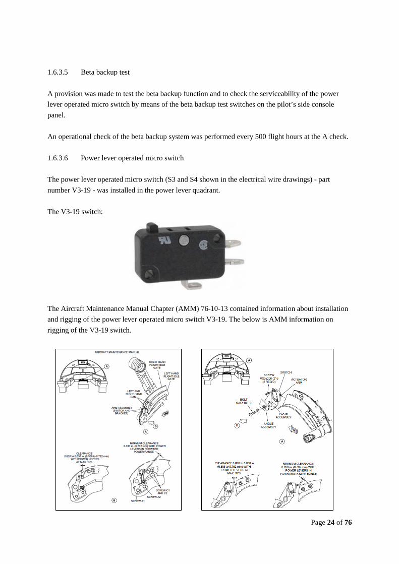
Power lever operated micro switch 1.6.3.6 The power lever operated micro switch (S3 and S4 shown in the electrical wire drawings) - part number V3-19 - was installed in the power lever quadrant. The V3-19 switch:
The Aircraft Maintenance Manual Chapter (AMM) 76-10-13 contained information about installation and rigging of the power lever operated micro switch V3-19. The below is AMM information on rigging of the V3-19 switch.

Page 25 of 76
1.6.4 Operator maintenance system records The operator maintenance system did not contain records of previously failed power lever operated micro switches. 1.6.5 Operational flight plan The AIB has erased the names of the crew members and the name of the operator. See appendix 5.1 1.6.6 Mass and balance The AIB has erased the names of the crew members and the name of the operator. See appendix 5.2 The total amount of fuel before flight was 1860 kilos. The total amount of fuel upon landing was 1171 kilos (with reference to the aircraft Flight Management System (FMS)). 1.6.7 Route performance manual (RPM) Below is an extract of the operator’s landing performance data for BGGH.
Page 26 of 76
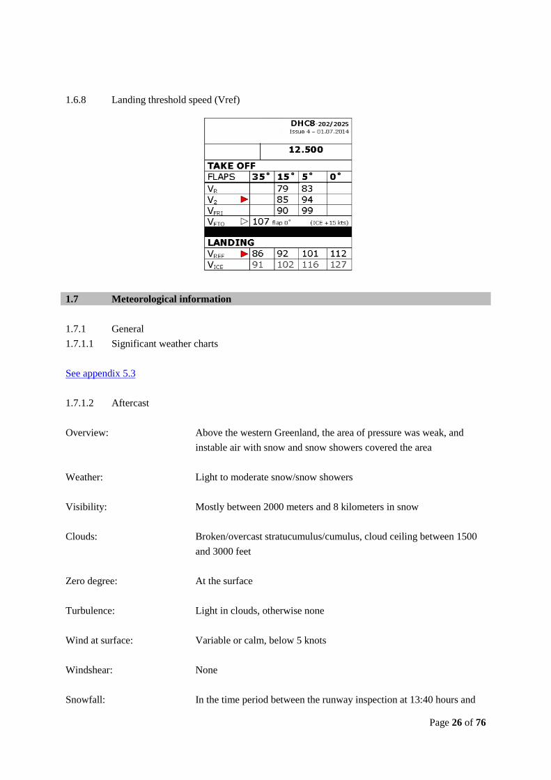
1.6.8 Landing threshold speed (Vref)
1.7 Meteorological information 1.7.1 General
Significant weather charts 1.7.1.1 See appendix 5.3
Aftercast 1.7.1.2 Overview: Above the western Greenland, the area of pressure was weak, and
instable air with snow and snow showers covered the area
Weather: Light to moderate snow/snow showers
Visibility: Mostly between 2000 meters and 8 kilometers in snow
Clouds: Broken/overcast stratucumulus/cumulus, cloud ceiling between 1500 and 3000 feet
Zero degree: At the surface
Turbulence: Light in clouds, otherwise none
Wind at surface: Variable or calm, below 5 knots
Windshear: None
Snowfall: In the time period between the runway inspection at 13:40 hours and
Page 27 of 76
the time of the serious incident, the snowfall intensified (light to moderate). Precipitation measurements between 12:00 and 15:00 hours indicated melted precipitation of 0.5 millimeters. When it comes to snow, precipitation measurements are not always reliable. Most likely, snowfall between 13:40 hours and the time of the serious incident accumulated between 0.5 and 1.5 centimeters of loose snow on the runway, as long as the snow had not been treated with snow melting agents. The previous evening/night, the air temperature was just above the freezing point, after which the temperature dropped to approximately minus 2° Celsius. This drop of temperature might have changed frozen ruts and ridges of snow into ice, if not melted by use of runway melting agents. Since 01:00 hours and with reference to weather synopsis for BGGH, the snowfall (mostly light snow) had been continuous.
1.7.2 Weather information - flight crew preflight planning At 13:34 hours, the flight crew updated their preflight planning weather information. The AIB extracted the below presented weather information.
BGGH 1.7.2.1 Aviation routine weather report (METAR) METAR: bggh 291250 03006kt 5000 –sn bkn022 ovc045 m01/m03 q0982=
Terminal Aerodrome Forecast ( (TAF) TAF: (9 hours)
bggh 291130z 2912/2921 16010kt 9999 bkn060 tempo 2912/2921 2500 –sn bkn020 =
BGPT 1.7.2.2
METAR: bgpt 291332z speci 16006kt 6000 -sn sct019 bkn026 m01/m04 q0983=
TAF: (9 hours)
bgpt 291207z 2912/2920 14006kt 9999 bkn060 tempo 2912/2920 3000 –sn bkn020 =
Page 28 of 76
1.7.3 METAR
BGGH 1.7.3.1 291150 bggh 291150z 03005kt 6000 -sn bkn022 ovc030 m01/m03 q0982=
291250 bggh 291250z 03006kt 5000 -sn bkn022 ovc045 m01/m03 q0982=
291350 bggh 291350z 02003kt 6000 -sn bkn028 ovc050 m02/m03 q0982=
291450 bggh 291450z 00000kt 3000 sn ovc030 m02/m03 q0982=
291550 bggh 291550z 00000kt 2000 sn ovc015 m02/m03 q0982=
BGPT 1.7.3.2
291150 bgpt 291150z 12006kt 9000 -sn bkn032 bkn061 m01/m05 q0983=
291250 bgpt 291250z 13006kt 9999 -sn sct032 bkn061 m01/m04 q0983=
291332 (SPECI)
bgpt 291332z 16006kt 6000 -sn sct019 bkn026 m01/m04 q0983=
291350 bgpt 291350z 18006kt 140v210 3500 sn bkn011 bkn016 m01/m04 q0983=
291420 (SPECI)
bgpt 291420z 14010kt 5000 -sn bkn016 bkn028 m02/m04 q0983=
291426 (SPECI)
bgpt 291426z 14008kt 3000 sn bkn012 ovc023 m02/m04 q0983=
291441 (SPECI)
bgpt 291441z 14009kt 1800 sn bkn012 ovc017 m02/m03 q0983=
1.7.4 TAF
BGGH 1.7.4.1 291103 bggh 291103z 2912/2921 16010kt 9999 bkn060 tempo 2912/2921 2500 -sn vv010=
291408 bggh 291408z 2915/2924 vrb06kt 9999 bkn060 tempo 2915/2924 2500 -sn vv010
becmg 2919/2922 18015kt=
BGPT 1.7.4.2 291023 bgpt 291023z 2910/2918 14005kt 9999 bkn060 tempo 2910/2918 3000 -sn bkn020=

Page 29 of 76
291207 bgpt 291207z 2912/2920 14006kt 9999 bkn060 tempo 2912/2920 3000 -sn bkn020=
291430 bgpt amd 291430z 2914/2920 14006kt 9999 bkn060 tempo 2914/2920 2500 -sn
vv007= 291457 bgpt 291457z 2915/2920 14008kt 5000 -sn bkn025 tempo 2915/2920 1400 sn
vv007= 1.7.5 Snow warning to airmen (SNOWTAM)
BGGH at 10:00 hours 1.7.5.1 swbg 0163 bggh 12291000 (snowtam 0163 a) bggh b) 12291000 c) 05 f) 78/78/78 g) 1/1/1 h) 5/5/5 n) 47/poor r) 47/poor t) rwy contamination 100 percent 1 mm ice and 050 percent 1 mm compacted snow, measured friction coefficient 35/40/40 tap - sweeping in progress)
BGGH at 11:05 hours 1.7.5.2 swbg 0164 bggh 12291105 (snowtam 0164 a) bggh b) 12291105 c) 05 f) 27/27/27 g) 1/1/1 h) 5/5/5 n) 47/poor r) 47/poor t) rwy contamination 050 percent 1 mm ice and 100 percent wet, measured friction coefficient 48-9/70-9/70-9 tap braking action unreliable - chemicals have been spread on runway, sweeping in progress)
BGGH at 13:45 hours 1.7.5.3 swbg 0165 bggh 12291345 (snowtam 0165 a) bggh b) 12291345 c) 05 f) 57/57/57 g) 1/1/1 h) 4/4/5 n) 47/poor r) 47/poor t) rwy contamination 050 percent 1 mm ice and 100 percent wet snow, braking action 40/48/50 tap, sweeping in progress)
Page 30 of 76
1.8 Aids to navigation 1.8.1 Circling RNAV GNSS - 1 approach The flight crew decided to perform a RNAV GNSS - 1 approach followed by a visual approach. 1.8.2 Notice to airmen (NOTAM) - BGGH a0370/14 notamr a0231/14 q) bggl/qnlas/iv/bo/a/000/999/ a) bggh b) 1411281808 c) 1502012000 e) nuuk locator qt freq 258 khz out of service. psn 64203973n051345489w. ref aip greeand ad2-bggh-4-19 b0574/14 notamr b0418/14 q) bggl/qcalt/iv/b/ae/000/999/ a) bggh b) 1411281809 c) 1502012000 e) bggh afis freq.119,100 mhz no coverage in sector between 060 deg mag and 210 deg mag below fl100. b0642/14 notamn q) bggl/qfmau/iv/bo/a/000/999/ a) bggh b) 1412281340 c) 1412291300 e) anemometer thr05 u/s, wind in metar is fm thr23. 1.8.3 Operator’s airport charts (extracts) See appendix 5.4 1.9 Communication 1.9.1 General The flight crew was in VHF radio contact with Sondrestrom FIC (121.300 MHz) and Nuuk AFIS (119.100 MHz). 1.9.2 Air Traffic Service (ATS) voice recording The AIB obtained involved ATS voice recordings. The recordings were of good quality and useful to the investigation.

Page 31 of 76
1.10 Aerodrome information
1.10.1 BGGH airport Airport position (ARP): 64 11 27.32N 051 40 41.03W ATS airspace: Nuuk Traffic Information Zone (TIZ).
Lateral limits: A circle 20 NM radius centered at 64 11 27.32N 051 40 41.03W (ARP) Vertical limits: 8000 feet mean sea level/ground
Elevation: 283 feet Magnetic variation: 30 W (January 2009) Runway identifications: RWY 05 and RWY 23 Direction of runway 05: 035.9° (GEO) and 070.9° (MAG) Direction of runway 23: 198.5° (GEO) and 228.5° (MAG) Surface: Asphalt Runway dimensions: 950 x 30 meters Landing distance available - RWY 23: 950 meters In circling area and at airport (remarks): All obstacles are marked by day and night Rescue and firefighting Service: CAT 5 Type of clearing equipment: Snow clearing equipment available Clearance priorities: Snow plan of Greenlandic airports - see appendix 5.5 Remarks: All seasons. Sanding will be used 1.10.2 Airport chart - ICAO Extract of the Aeronautical Information Publication (AIP) - Greenland. See appendix 5.6 1.10.3 Airport winter operations preparedness
Airport winter preparedness equipment 1.10.3.1
- Two trucks, each capable of pulling a snow clearing sweeper - One snow clearing sweeper in operation and one snow clearing sweeper on standby - One loader - One truck prepared for spreading melting agents and/or sand - One car prepared for performing retardation measurements: Tapley-meter
Page 32 of 76
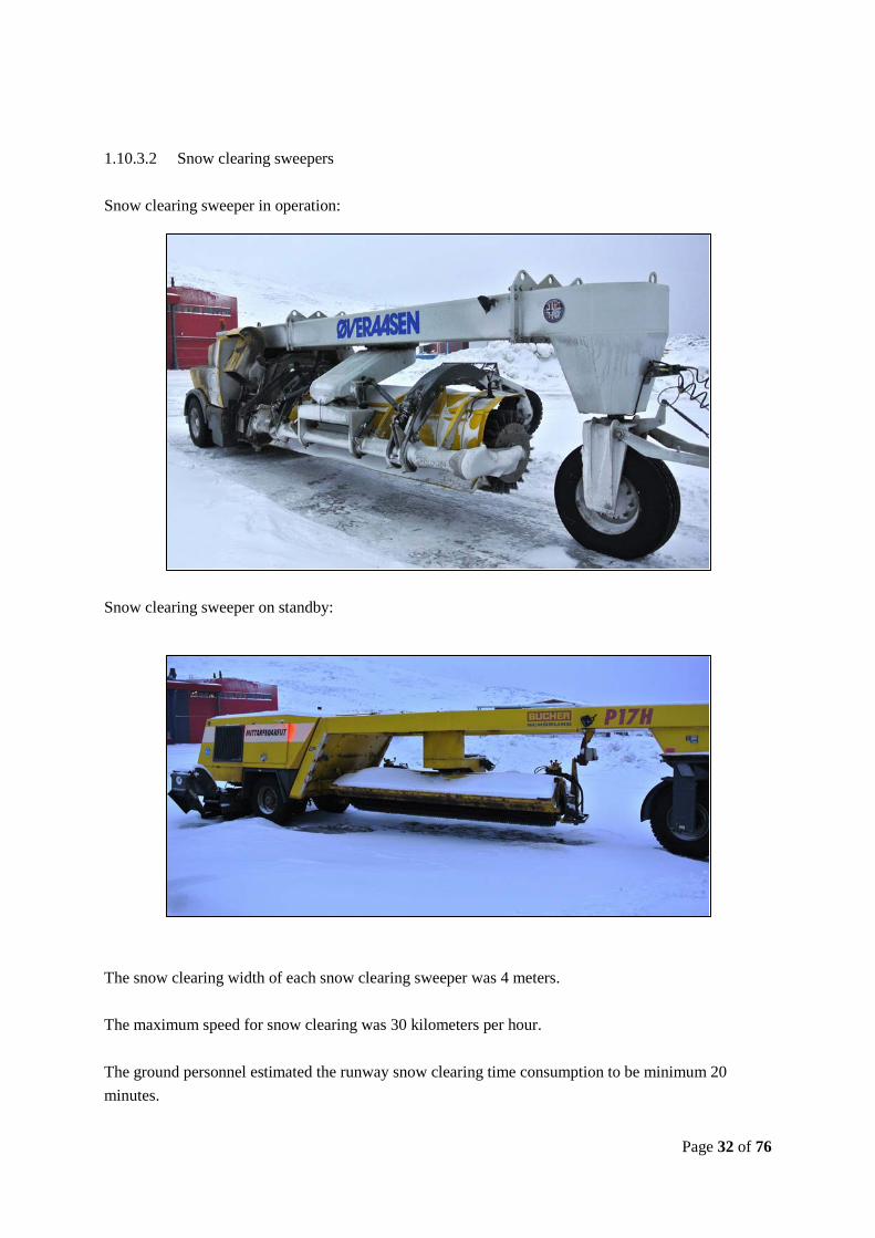
Snow clearing sweepers 1.10.3.2
Snow clearing sweeper in operation:
Snow clearing sweeper on standby:
The snow clearing width of each snow clearing sweeper was 4 meters. The maximum speed for snow clearing was 30 kilometers per hour. The ground personnel estimated the runway snow clearing time consumption to be minimum 20 minutes.

Page 33 of 76
Melting agent and/or sand spreader 1.10.3.3
Car equipped with Tapley-meter 1.10.3.4

Page 34 of 76
1.11 Flight recorders 1.11.1 Solid State Flight Data Recorder (SSFDR)
Manufacturer: Honeywell, Part Number 980-6020-001 (Serial Number 1465) The SSFDR appeared undamaged, and the recovered flight data were useful to the investigation.
SSFDR data plots 1.11.1.1 The time axis is in Universal Coordinated Time (UTC). The SSFDR data of interest are plotted in appendix 5.7 to appendix 5.11 1.11.2 Solid State Cockpit Voice Recorder (SSCVR) Manufacturer: Honeywell, Part Number 980-4700-001 (Serial number 1860) The SSCVR appeared undamaged. The SSCVR data were recovered and were useful to the investigation. 1.11.3 Flight Management System (FMS) The two FMS units appeared undamaged. The FMS data of both units were recovered and were useful to the investigation. The FMS data was overlaid with data from the SSFDR for comparison. In general, there was good agreement between the two data sets.

Page 35 of 76
1.12 AIB safety investigation 1.12.1 Place of serious incident The aircraft came to a stop in the safety zone 45 meters east of the runway centre line to runway 23 and 110 meters south of the apron taxiway side stripe (latest position recorded by the aircraft FMS).
The AIB has removed the name of the operator.

Page 36 of 76
1.12.2 Safety investigation Technical investigation 1.12.2.1
1.12.2.1.1 The right hand power lever operated micro switch The photo below shows a factory new micro switch with the plunger correctly in place, ready for activation of the micro switch. Activation of the micro switch is done when the plunger is moved towards the micro switch housing. The plunger is kept in this place by means of an internal spring inside the micro switch housing. The photos below show the affected right hand power lever operated micro switch and a factory new micro switch.
Affected micro switch removed from OY-GRK
The plunger is not spring loaded. No micro switch function and the plunger moved freely and disappeared inside the micro switch housing.
Factory new micro switch The plunger is spring loaded and when pressed, the micro switch function was audible. Affected micro switch removed from OY-GRK
The plunger is not spring loaded. No micro switch function and the plunger moved freely. Factory new micro switch

Page 37 of 76
1.12.2.1.2 Flight Data Monitoring (FDM) A review of the operator’s Quick Access Recorder (QAR) data revealed recordings of momentary activation of the right hand propeller beta backup protection (feather signal) in four out of five previous flights. At the time of the serious incident, the operator’s FDM system was not pre-set to display feather signal warnings.
Operational investigation 1.12.2.21.12.2.2.1 Airport winter preparedness equipment Status of the airport winter preparedness equipment at the time of the serious incident:
- One truck was occupied by refuelling tasks and thereby not at the disposal of the airport snow clearing services
- One truck was occupied by continuous runway snow clearing - The melting agent and/or sand spreader was out of service (since 28-12-2014) - The loader was not in use - One snow clearing sweeper was in operation - The purpose of the standby snow clearing sweeper was solely to be standby equipment and
could not immediately be brought into runway snow clearing services - The latest calibration of the Tapley-meter on 31-5-2013 did not give rise to remarks
1.12.2.2.2 Clearing of runway snow and ice deposits In the morning on the day of the serious incident, the runway on both side of the centreline was covered with ice in areas from the runway edge and approximately 8 meters towards the runway centreline. Since the melting agent and/or sand spreader was out of service, ground personnel in the morning and in certain areas spread out melting agents by hand. Throughout the day of the serious incident, it had been continuously snowing. When airport traffic permitted, one truck pulling a snow clearing sweeper continuously swept the runway. Sweeping time on the runway:
Time period Minutes
12:02 - 12:24 hours: 22 minutes

Page 38 of 76
12:32 - 12:39 hours: 7 minutes 12:43 - 12:54 hours: 11 minutes 13:05 - 13:21 hours: 16 minutes 13:31 - 13:56 hours: 25 minutes 14:08 - 14:20 hours: 12 minutes 14:31 - 14:53 hours: 22 minutes 15:09 - 15:24 hours: 15 minutes Due to airport traffic, it was not possible to sweep the runway in full width every time. At the time of the serious incident, it was the perception that the runway had been swept clear of ice down to the asphalt covering a width of 6 meters on each of the runway centreline. However, the whole runway was covered with snow. 1.12.2.2.3 Runway inspections In the time period between 09:30 and 13:40, seven runway inspections were performed. Runway inspection reporting:
Time
Runway inspection reporting
09:30 hours: Braking action coefficients valid for runway 05 were in writing reported to be 40, 43 and 33. There was no documented written reporting on prevailing runway contamination.
10:15 hours: Braking action coefficients valid for runway 05 were in writing reported to be 35, 40 and 40. 25% of the runway was covered with 2-3 millimetres of dry snow. 50% of the runway was covered with 1 millimetre of compacted snow. 100% of the runway was covered with 1 millimetre of ice. Braking action coefficient valid for taxiways was reported to be 20. 100% of the taxiway was covered with 2 millimetres of dry snow.
10:32 hours: A recording of radio communication at 10:32 hours revealed a verbal report on braking action coefficients for runway 05 of 40, 43 and 33. 100% of the runway was covered with 1 millimetre of ice. 100% of the runway was covered with 2 millimetre of melting snow due to the spreading of melting agents.
Page 39 of 76
There was no documented written reporting on the prevailing runway conditions.
11:07 hours: A recording of radio communication at 11:07 hours revealed a verbal report on braking action coefficients for runway 05 of 48, 70 and 70. 50% of the runway was covered with 1 millimetre of ice. 100% of the runway was wet due to melting agents. There was no documented written reporting on the prevailing runway conditions.
12:30 hours: Braking action coefficients valid for runway 05 were in writing reported to be 24, 38 and 45. There was no documented written reporting on runway contamination. A recording of radio communication at 12:26 hours revealed a verbal report on braking action coefficients for runway 05 of 24, 38 and 45. 100% of the runway was covered with 1 millimetre of ice. 25% of the runway was covered with 3 millimetre of dry snow, mainly along the runway edges. 100% of the runway was covered with 1 millimetre of wet snow.
12:53 hours: A recording of radio communication at 12:53 hours revealed a verbal report on braking action coefficients for runway 05 of 43, 47 and 47. 100% of the runway was covered with 1 millimetre of wet snow. There was no documented written reporting on the prevailing runway conditions.
13:40 hours: Braking action coefficients valid for runway 05 were in writing reported to be 40, 48 and 50. 50% of the runway was covered with 1 millimetre of ice. 100% of the runway was covered with 1 millimetre of wet snow. Braking action coefficient valid for taxiways was reported to be 20. 100% of the taxiway was covered with 2 millimetres of wet snow and ice.
On request by the AIB, additional runway inspections were performed.
Page 40 of 76
Runway inspection reporting:
Time
Runway inspection reporting
15:46 hours: Braking action coefficients valid for runway 05 were reported to be 19, 21 and 21. 50% of runway covered with 1 millimetre of ice. 100% of the runway covered with 1 millimetre of dry snow.
16:22 hours: Braking action coefficients valid for runway 05 were reported to be 16, 16 and 17. 100% of the runway was covered with 5 millimetres of dry snow. 100% of the runway was covered with 1 millimetre of ice.
16:24 hours: Braking action coefficients - valid for runway 05 measured at 6 metres from and on each side of the runway centreline - were reported to be 15, 17 and 15. 100% of the runway was covered with 5 millimetres of dry snow. 100% of the runway was covered with 1 millimetre of ice.
1.12.2.2.4 Airport braking action measurement instruction The below instruction is translated into English by the AIB. Before measuring the braking action coefficients, the Tapley-meter is set to zero. The measurements are performed at a speed of 40 kilometres per hour, and the Tapley-meter instrument is set to “TEST”. Measurements are performed along two parallel lines in the longitudinal direction of the runway (approximately 4 meters on each side of the centreline). Three braking measurements are performed on each side of the centreline (one for each third of the runway). The average of each third is calculated, and the result is immediately reported to AFIS. Braking measurements on the apron are only performed on request by AFIS. When more than 11% or more of the total area of the runway is covered with slush, wet snow/or wet ice, the code number (unreliable) is given.
Page 41 of 76
1.12.2.2.5 Airport personnel employed at BGGH airport At Nuuk, 19 employees were employed by Greenlandic Airports.
- One airport manager - One works director - Three on-site commanders - Four AFIS operators - Eight terminal workers - One service technician - One traffic assistant
The tasks allocated to the abovementioned airport personnel were:
- Fire and rescue services - Handling of foreign carriers - Fuelling of domestic and foreign carriers - Security checks - Maintenance of airport buildings, runway and runway systems - Winter operations (snow and ice deposits clearing) - Measurement of braking action - Air Traffic Service (AFIS) - Administration
When handling a foreign carrier, the minimum handling personnel were four. Before the time of the serious incident, one on-site commander (in charge of all airport ground operations), one service technician, and two terminal workers were occupied by handling a foreign carrier. One on-site commander performed the runway snow clearing task. In order to meet the actual workload of the handling personnel, the security personnel were reduced from four to three persons. Within the previous two years, that total airport traffic operations at BGGH had increased, and the number of terminal workers had been reduced from ten to eight. One of the two reduced terminal man-years had been replaced by a service technician. 1.12.2.2.6 Supreme authority to close runway and/or airport Regarding closing the runway and/or the airport due to snow and/or ice deposits clearing, it was the perception of the airport personnel that no clarified airport supreme authority was at place.
Page 42 of 76
It was the perception of the airport personnel that the airport remained open for operations until aircraft operators no longer wanted to operate at the airport. 1.13 Medical and pathological information None. 1.14 Fire There was no fire. 1.15 Survival aspects 1.15.1 Seats and seatbelts The passengers and the crew were using seatbelts. Neither seats nor seatbelts were overstressed or suffered from malfunctioning. 1.15.2 Runway excursion The aircraft departed the runway at approximately 35 knots and ended up in loose snow in the safety zone. On the basis of the sequence of events, the flight crew decided that evacuation of the aircraft was not necessary. The passengers and the crew members disembarked the aircraft through the airstair door. 1.16 Tests and research None.

Page 43 of 76
1.17 Organization and management information 1.17.1 The operator
General 1.17.1.1 The operator was the largest air carrier in Greenland and constituted a major part of the Greenlandic traffic infrastructure. The aircraft fleet consisted of helicopters, twin-engine turboprop aircraft and one long-haul aircraft. The area of operation (passengers, cargo and emergency medical service) was mainly the European and North Atlantic region. The long-haul aircraft was approved for a worldwide operation. The operator was the certificate holder of an approved maintenance organization. The operator’s Air Operator Certificate (AOC) held an approved Operations Manual (OM) system containing operational documentation and limitations, and standard operating procedures (SOP).
The operator’s Safety Management System (SMS) 1.17.1.2
For the purpose of operational control, the operator held an approved SMS including FDM.
Operations Manual 1.17.1.31.17.1.3.1 Operations Manual Part A Definitions: Circling: The visual phase of an instrument approach to bring an aircraft into position for landing on a runway which is not suitably located for a straight-in approach. Visual Approach: An approach when either part or all of an instrument approach procedure is not completed and the approach is executed with visual reference to the terrain. Visual approach (extract)
8.1.3.3.12 Visual Approach When performing visual approach, the aerodrome and/or the landing runway environment or other markings identifiable with the airport must be in sight continuously.
Page 44 of 76
Braking action See appendix 5.12 1.17.1.3.2 Operations Manual Part B Stabilized approach concept See appendix 5.13 Landing on contaminated or slippery runways (extract) See appendix 5.14
1.17.2 Nuuk airport
General 1.17.2.1 Nuuk airport was part of a larger Greenlandic airport organization - Greenlandic Airports. Greenland Airports provided services to a number of aircraft operators, the Greenlandic society and private companies. Greenlandic Airports managed the complete air transportation of passengers and cargo in Greenland, divided between 13 airports and 46 helipads.
Nuuk Airport Operations Manual - extracts 1.17.2.21.17.2.2.1 Snow clearing The extracts are translated into English by the AIB - see appendix 5.15 1.18 Additional information None. 1.19 Useful or investigation techniques None.

Page 45 of 76
2 ANALYSIS
2.1 General The licenses and qualifications held by the flight crew and the AFIS operator, flight and duty times, the documented technical and known maintenance status of the aircraft, the aircraft mass and balance and the aids to navigation had, in the AIB’s opinion, no influence on the sequence of events. 2.2 Pre-flight planning The flight crew planned the flight from BGGH to BGPT with the destination alternate aerodrome BGGH. Generally seen, the actual weather conditions at BGGH and en route weather were equivalent to the forecasted weather conditions. Furthermore, issued SNOWTAMs for BGGH did not give rise to any flight crew unexpected pre-flight planning tasks considering operating in an arctic area in the winter. 2.3 SNOWTAM for BGGH In the time period from 09:30 hours until 13:40 hours, seven runway inspections were performed (at 09:30 hours, at 10:15 hours, at 10:32 hours, at 11:07 hours, at 12:30 hours, at 12:53 hours and at 13:40 hours). In five out of seven runway inspections, there was no documented written reporting on prevailing runway conditions. In the time period from 10:00 hours until 13:45 hours, three SNOWTAMs were issued (at 10:00 hours, at 11:05 hours, and at 13:45 hours). Taking into consideration the time of the performed runway inspections and the issue time of the SNOWTAMs, the AIB finds that the issued SNOWTAMs reflected the performed runway inspections and the reported visual observations of runway contamination. 2.4 Approach to BGGH 2.4.1 RNAV GNSS - 1 approach followed by a visual approach to runway 23 By Sondrestrom Information and by Nuuk AFIS, the flight crew got information of runway 23 in use and prevailing traffic information at BGGH (one arriving aircraft from BGSF and one departing aircraft from BGGH).
Page 46 of 76
For cloud breaking, the flight crew planned and set up the RNAV GNSS - 1 approach with the purpose of performing a visual approach to runway 23. Considering the actual weather conditions and the prevailing traffic in Nuuk TIZ, the AIB does not find the mutual traffic perception and coordination among involved flight crews and Nuuk AFIS to be optimum due to aircraft on opposite approaches ( in case of missed approaches) and a departing aircraft on an approximate opposite course to an approaching aircraft. With reference to the operator’s approach chart, the RNAV GNSS - 1 approach was restricted to maximum 130 knots. The aircraft passed the IAF UVIRI at an altitude of approximately 600 feet lower than the specified minimum altitude and with a CAS of approximately 49 knots higher than the restricted maximum speed. The aircraft passed the IF GONEN at 3900 feet with a CAS of approximately 47 knots higher than the restricted maximum speed. No flight crew call out on stabilized approach was made when passing 1000 feet AAL. Though these findings were not consistent with the operator’s procedures, they did not in the AIB’s opinion have impact on the sequence of events. Before passing the MAP ADMIP, the flight crew established visual contact with terrain and later on other markings identifiable with the airport. On right base to runway 23 and in low visibility, the flight crew established visual contact with the runway, and the pilot flying had to make a steep turn in order to establish the aircraft on final to runway 23. With reference to the operator’s stabilized parameters and when passing 300 feet AAL, the aircraft was just within the stabilized approach parameters. Generally seen, the performed RNAV GNSS - 1 approach followed by the visual approach to runway 23 did not have influence on the sequence of events. 2.4.2 Mutual flight information and traffic coordination The AIB finds that in-depth flight information of runway conditions (when present) to every flight crew at every initial radio call combined with the use of standard radio communication phraseology optimizes traffic coordination and flight crew decision making.

Page 47 of 76
Thereby, the overall flight safety is increased. 2.5 Runway excursion 2.5.1 Reported braking action coefficients The AIB requested measurements and observations in relation to runway conditions were performed at 15:46 hours, at 16:22 hours, and at 16:24 hours. In the light of these measurements and observations, the reported weather conditions and braking action coefficients at and following the time of the serious incident, and the actual sequence of events, the AIB is of the opinion that the actual runway conditions at the time of the serious incident and the runway conditions investigated by the AIB subsequently (at 15:46 hours) may have been identical. The melting agent and/or sand spreader was out of service precluding the airport from an effective runway ice deposits clearing throughout the day of the serious incident, which probably changed the runway conditions of melted snow (wet runway) in the morning (local time) into a partly ice covered runway at noon (local time). Therefore, it is the AIB’s opinion that braking action coefficients at a distance greater than approximately 6 meters east and west of the centreline for runway 23 at the time of the serious incident may have been considerably less than those reported (measured at a distance of 4 metres each side of the runway’s centre line). Furthermore, the AIB finds it probable that more extensive areas of the runway to the east and west of the centreline of runway 23 may have been contaminated with ice at the time of the serious incident. Generally, it is the AIB’s view that braking action coefficients should be used for guidance only, which is supported by the fact that the reported prevailing braking action coefficients only constituted values measured at a distance of 4 metres to each side of the centreline. Furthermore, the runway braking action tests at BGGH were done by means of a Tapley-meter (only indicating peak values of retardation reached during braking), which in the aviation community is considered to be less accurate and reliable than other surface friction testers. On top of this, the prevailing reported braking action coefficients were most recently measured at 13:40 hours. Thus, due to the fact that almost two hours had elapsed between the time the most recent measurement was taken and the time of the serious incident, the AIB questions the validity of the reported values. Comparing the actual sweeping times on the runway versus the described and estimated time consumption for sweeping of the runway at BGGH (40 minutes cf. the Airport Operations Manual/minimum 20 minutes cf. the estimation of the ground personnel), the AIB questions the cleared runway width to be 30 meters at the time of serious incident.

Page 48 of 76
The reported braking action coefficients formed the basis for the flight crew’s decision to land on runway 23 under the prevailing runway conditions. However, the method of measurement and reporting used did not, in the AIB’s opinion, adequately establish the landing runway’s effective braking action coefficient values. Considering the aircraft landing performance data, the availability of effective braking action coefficient values would have made a landing on runway 23 marginal and might probably have changed the flight crew’s decision to land on runway 23 under the prevailing runway conditions. 2.5.2 The right hand power lever operated micro switch At the time of the serious incident, neither the operator’s maintenance system nor the operator’s FDM contained information on previously failed power lever operated micro switches. Upon landing on runway 23, the right hand power lever operated micro switch failed momentarily resulting in the propeller control system to momentarily react as the aircraft still was in flight and thereby causing the right hand propeller to begin momentarily feathering (beta backup protection). In ground beta range with a right hand momentarily feathering propeller, the aircraft started veering to the left. 2.5.3 Runway excursion It is the opinion of the AIB that the combination of the aircraft’s trajectory to the left - as a consequence of a right hand momentarily feathering propeller - and the prevailing runway contamination during the last part of the landing roll had a negative impact on the deceleration and the flight crew’s ability to maintain directional control of the aircraft, which resulted in the aircraft running off the left side of the runway. The decision on making a ground loop in the safety zone reduced the risk of aircraft damages and injuries to persons.
Page 49 of 76
2.6 Runway snow clearing at BGGH In the AIB’s point of view, several conditions in combination had influence on a non-optimum runway snow and ice deposits clearing and reporting at BGGH on the day of the serious incident:
- There was continuous snowfall - Only one snow clearing sweeper in operation reduced the capability of in whole runway
snow clearing in appropriate time - The melting agent and/or sand spreader was out of service precluding an effective runway
ice deposits clearing - At peak working conditions, there was an imbalance between ground personnel allocated
tasks and ground personnel allocated resources, which might unintentionally have diverted focus from flight safety to regularity tasks
- Though described, there was no decisive perception by airport personnel on supreme authority to close down temporarily all airport operations for appropriate runway snow and ice deposits clearing
- Airport measurement procedures and reporting on runway contamination - including braking action coefficient values - did not in-full reflect the prevailing runway contamination and the runway’s effective braking action coefficient values

Page 50 of 76
3 CONCLUSIONS
3.1 Findings 1. The licenses and qualifications held by the flight crew and the AFIS operator, flight and
duty times, the documented technical and known maintenance status of the aircraft, the aircraft mass and balance and the aids to navigation had no influence on the sequence of events
2. The operator maintenance system did not contain records of previously failed power lever operated micro switches.
3. The actual weather conditions at BGGH and en route weather were equivalent to the forecasted weather conditions
4. During the day of the serious incident, there was continuous snowfall 5. Issued SNOWTAMs for BGGH did not give rise to any flight crew unexpected pre-flight
planning tasks 6. In five out of seven runway inspections, there was no documented written reporting on
prevailing runway conditions 7. The issued SNOWTAMs reflected the performed runway inspections and the reported
visual observations of runway contamination 8. For cloud breaking, the flight crew planned and set up the RNAV GNSS - 1 approach with
the purpose of performing a visual approach to runway 23 9. Mutual traffic perception and coordination among involved flight crews and Nuuk AFIS
was not optimum 10. The RNAV GNSS - 1 approach was restricted to maximum 130 knots 11. The aircraft passed the IAF UVIRI at an altitude of approximately 600 feet lower than the
specified minimum altitude and with a CAS of approximately 49 knots higher than the restricted maximum speed
12. The aircraft passed the IF GONEN at 3900 feet with a CAS of approximately 47 knots higher than the restricted maximum speed
13. No flight crew call out on stabilized approach was made when passing 1000 feet AAL 14. Before passing the MAP ADMIP, the flight crew established visual contact with terrain and
later on other markings identifiable with the airport 15. On right base to runway 23 and in low visibility, the flight crew established visual contact
with the runway 16. The pilot flying had to make a steep turn in order to the establish aircraft on final to runway
23 17. Passing 300 feet AAL, the aircraft was just stabilized 18. The performed RNAV GNSS - 1 approach followed by the visual approach to runway 23
did not have influence on the sequence of events 19. The actual runway conditions at the time of the serious incident and the runway conditions
investigated by the AIB subsequently (at 15:46 hours) may have been identical
Page 51 of 76
20. The melting agent and/or sand spreader was out of service precluding the airport from an effective runway ice deposits clearing
21. Braking action coefficients at a distance greater than approximately 6 meters east and west of the centreline for runway 23 at the time of the serious incident may have been considerably less than those reported (measured at a distance of 4 metres each side of the runway’s centre line)
22. More extensive areas of the runway to the east and west of the centreline of runway 23 may have been contaminated with ice at the time of the serious incident
23. The prevailing reported braking action coefficients were most recently measured at 13:40 hours
24. The cleared runway width may not have been 30 meters at the time of serious incident 25. Airport measurement procedures and reporting on runway conditions - including braking
action coefficient values - did not in-full reflect the prevailing runway contamination and the runway’s effective braking action coefficient values
26. Upon landing on runway 23, the right hand power lever operated micro switch failed momentarily resulting in the propeller control system to momentarily react as the aircraft still was in flight and thereby causing the right hand propeller to begin momentarily feathering (beta backup protection)
27. In ground beta range with a right hand momentarily feathering propeller, the aircraft started veering to the left
28. A review of the operator’s QAR data revealed recordings of momentary activation of the right hand propeller beta backup protection (feather signal) in four out of five previous flights
29. The operator’s FDM system was not pre-set to display feather signal warnings 30. The prevailing runway contamination during the last part of the landing roll had a negative
impact on the deceleration and the flight crew’s ability to maintain directional control of the aircraft
31. The decision on making a ground loop in the safety zone reduced the risk of aircraft damages and injuries to persons
32. Only one snow clearing sweeper in operation reduced the capability of in whole runway snow clearing in appropriate time
33. At peak working conditions, there was an imbalance between ground personnel allocated tasks and ground personnel allocated resources, which might unintentionally have diverted focus from flight safety to regularity tasks
34. There was no decisive perception by airport personnel on supreme authority to close down temporarily all airport operations for appropriate runway snow and ice deposits clearing

Page 52 of 76
3.2 Factors 1. Upon landing on runway 23, the right hand power lever operated micro switch failed
momentarily resulting in the propeller control system to momentarily react as the aircraft still was in flight and thereby causing the right hand propeller to begin momentarily feathering (beta backup protection)
2. The prevailing runway contamination during the last part of the landing roll had a negative impact on the deceleration and the flight crew’s ability to maintain directional control of the aircraft
3.3 Summary Upon landing on runway 23 at Nuuk (BGGH) and shortly after having selected reverse on both engines, the flight crew experienced that the aircraft unexpectedly started to veer to the left. The pilot flying attempted to correct this by deactivating reverse on both engines and by use of the wheel brakes and the nose wheel steering, but the aircraft continued veering towards the left side of the runway. The aircraft ran off the left side of the runway and came to a complete stop in the safety zone. A momentary failure of the right hand power lever micro switch causing a momentary activation of the right hand propeller beta backup protection in combination with a divergence between reported and effective braking action coefficients on runway 23 had a negative effect on the flight crew’s ability to maintain directional control, which resulted in the aircraft running off the side of the runway. Neither passengers nor crew members suffered any injuries. There were no damages to the aircraft. The serious incident occurred in daylight and under visual meteorological conditions (VMC). The safety investigation did not result in recommendations being made.

Page 53 of 76
4 SAFETY RECOMMENDATIONS
4.1 Area of safety focus Based on the safety investigation of this serious incident, the AIB would like to point out an area of safety focus, in which an evaluation of potential preventive actions would be appropriate:
- An evaluation of general winter operations preparedness at Greenlandic airports (including equipment (hardware), procedures (software) and manpower (liveware)
4.2 Preventive actions 4.2.1 The operator
Checklist item 4.2.1.1 The operator introduced a new checklist item (Beta Back-up Test) to the aircraft 24 hour check:
The FDM system 4.2.1.2
The FDM system was pre-set to display feather signal warnings. 4.2.2 Greenlandic Airports As a consequence of this serious incident, Greenlandic Airports issued two safety bulletins:
1. Runway inspection, including methods of measurements and reporting 2. Content of SNOWTAM and use of standard ATS phraseology
Page 54 of 76
5 APPENDICES
5.1 Operational flight plan 5.2 Mass and balance 5.3 Significant weather charts 5.4 Operator’s airport charts (extract) 5.5 Snow plan - Aeronautical Information Publication (AIP) Greenland 5.6 Airport chart - ICAO 5.7 SSFDR approach 5.8 SSFDR landing 5.9 SSFDR longitudinal controls 5.10 SSFDR lateral controls 5.11 SSFDR engine/propellers 5.12 Braking action 5.13 Stabilized approach concept 5.14 Landing on contaminated or slippery runways 5.15 Airport Operations Manual - snow clearing (extract)

Page 55 of 76
5.1 Operational flight plan Click back to page

Page 56 of 76
5.2 Mass and balance Click back to page
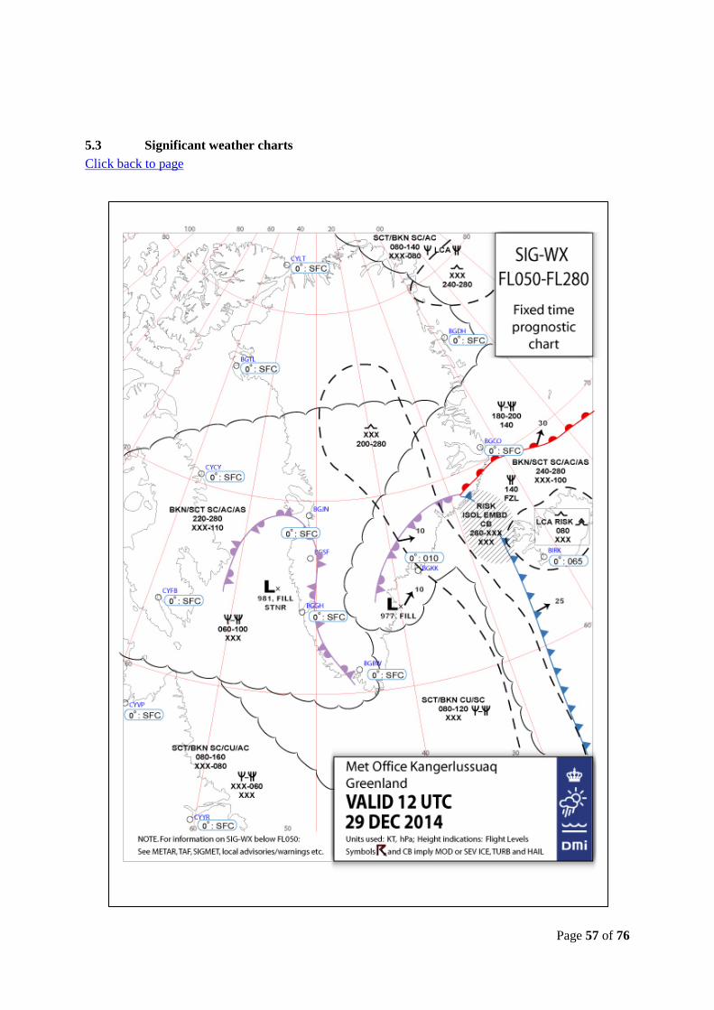
Page 57 of 76
5.3 Significant weather charts Click back to page
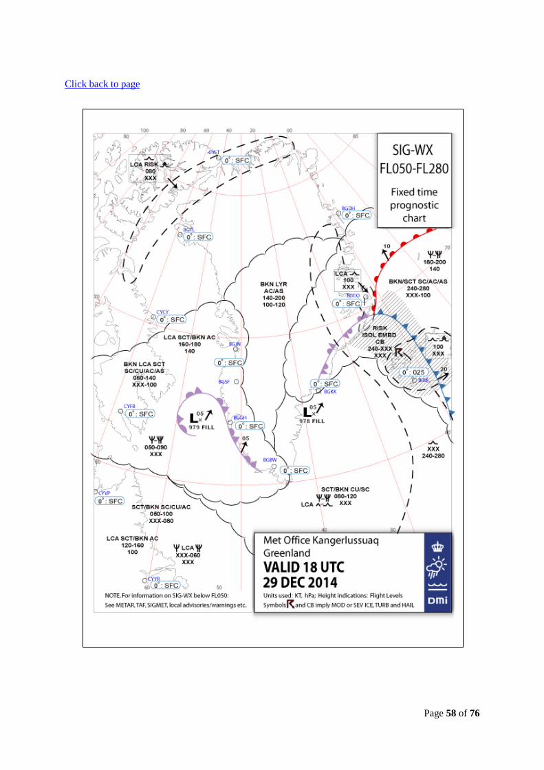
Page 58 of 76
Click back to page

Page 59 of 76
5.4 Operator’s airport charts Click back to page
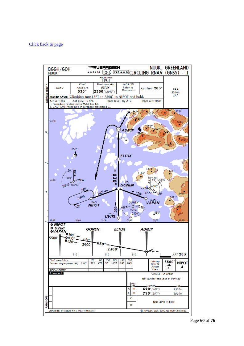
Page 60 of 76
Click back to page

Page 61 of 76
5.5 Snowplan - Aeronautical Information Publication (AIP) Greenland Click back to page 2. Snowplan 2.1 Organization of winter service The winter service will be conducted by the Aerodrome Operational Service at the aerodromes listed below, and consists of the following duties: a) Surveillance of the manoeuvring area and apron with a view to note presence of ice or snow. b) Measurement of the friction coefficient or estimate of the braking action when ice and/or snow are present at the runway in use, and as far as possible at taxiway and apron. c) Implementation of measures to maintain the usability of the runway etc. d) Reporting concerning the conditions mentioned in item a) to c). 2.1.1 Winter service is established at the following aerodromes: Aasiaat, Ilulissat, Kangerlussuaq, Kulusuk, Maniitsoq, Narsarsuaq, Nerlerit Inaat, Nuuk, Paamiut, Qaanaaq, Sisimiut, Upernavik, Uummannaq/Qaarsut, Additionally winter service is established in accordance with USAF rules at Thule Airbase. 2.2 Surveillance of the manoeuvring area at aerodromes The Aerodrome Operational Service monitors runways, taxiways and apron within the published aerodrome hours of service. Surveillance outside these hours must be arranged with the local Airport Authority. 2.3 Surveillance of the manoeuvring area at heliports At heliports a limited surveillance of the maneouvring area and apron is carried out, with the purpose of detecting ice or snow. The friction coefficient is not measured. Snow clearance is carried out when big amounts of snow is present, but it is to be expected that the surface will be covered by snow, compacted snow and ice in the winter period. Braking action in the winter period can be expected to be reduced due to deposits of snow and ice. 3. Measurements etc. 3.1 The depth of a layer of snow is measured by an ordinary measuring rod. Measurements will be taken at such a high number of places that a representative mean value may be computed. On a runway the mean value will be computed for each third of the runway. 3.2 Friction coefficients Whenever information on braking action promulgated in accordance with this SNOWPLAN in terms of friction coefficients is used as a basis for assessing stopping and manoeuvring capability of an

Page 62 of 76
aircraft, it is of utmost importance to keep in mind, that these friction coefficients are those pertaining to a measuring device, and therefore as objective parameters valid for that specific device only. From experiments it is known that the measuring results obtained by simultaneous testing of the same surface with different measuring devices are not the same and in certain cases can deviate considerably. It is also a well-established fact that none of the measuring methods so far developed have proved the ability to provide information that under all circumstances can be used with confidence as guidance for the prediction of an aircraft's behaviour in respect to stopping and manoeuvring performance. In this respect the shortcomings of the measured friction values are particularly pronounced in situations where slipperiness is a consequence of the lubricating action of wet snow or water between tires and surface. Under such circumstances, and also when ice or compacted snow is present at surface temperatures near freezing point, it is strongly adviced to plan and prepare for the possibility that stopping and steering qualities may be far inferior to what would be expected when considering the measured friction numbers in isolation. 3.2.1 The following methods of measurement will apply: a) Continuous method, whereby the friction coefficient is recorded continuously by special devices constructed for this purpose: • Surface Friction Tester, high pressure tire (SFH), • Surface Friction Tester, low pressure tire (SFL), • Mu-meter (MUM), • Skiddometer (SKH). b) Retardation measurements with the use of an instrument that only indicates the peak value of the retardation reached during each braking: Tapley-meter (TAP). All measurements and calibrations are accomplished in accordance with the instruction for the proper use of the instruments, given by the manufacturer. Measurements are taken on each side of the centre line at a distance of approximately 4 metres. 3.2.1.1 TAP is used at the aerodromes listed in item 2.1. Some aerodromes have reserve instruments. If a reserve instrument of another type than the primary is used it will be announced by ATS. 3.2.1.2 Braking action will be estimated if the friction coefficient cannot be measured due to lack of equipment or for other reason.

Page 63 of 76
4. Measures to maintain the usability of runway 4.1 Snow clearance and measures for improvement of braking action will be implemented and maintained as long as conditions at the movement area may impede the safety and regularity of air traffic. 4.2 Snow clearance etc. will normally be carried out in the following order: 1. Runway in use and access road from the fire station. 2. Taxiway(s) to runway in use. 3. Apron. 4. Other runways and areas. Measures will be taken to clear the runways to full width but in special cases conditions may cause that wide runways temporary will be opened for traffic even if cleared to a width of 30 metres only. The snow clearance will not be considered to be completed before the runway is cleared to full width. 4.3 Measures for improvement of braking action will be implemented when the friction coefficient on runways and/or taxiways is below 0.30. 4.3.1 For removal of ice and compacted snow which cannot be removed with mechanical equipment, and at times to prevent ice to build, below mentioned chemicals will be used. For spraying: - UCAR and a mixture of pure ethylene glycol and isopropyl alcohol. - ethylene glycol (CH2)(OH)(CH2)(OH)(UCAR). - propylene glycol (CH2)(OH)(CH)(OH)(CH3). - potassiumacetat/Clearway One and Safeway KA (CH3COOK). For spreading: - UREA ((NH2)2Co). - sodium acetate/Clearway Two and Safeway SD (2NaHCOO). Chemical de-icing of runways will be carried out to a width of at least 15 metres on each side of the centre line. 4.3.2 Improvement of the braking action by spreading of sand may take place under special circumstances. The grain size will not exceed 3.5 millimetres at aerodromes used by jet aircraft, and 5 millimetres at aerodromes used by piston aircraft.

Page 64 of 76
5. Reporting 5.1 The Aerodrome Operational Service will use the SNOWTAM Format for the reporting which will be delivered to the Aerodrome Reporting Office/Air Traffic Service unit for further dissemination. SNOWTAM format used is in accordance with latest valid ICAO Annex 15 and Eurocontrol "SNOWTAM Harmonisation Guidelines" 5.1.1 When ice or snow no longer prevail and chemicals no longer is used, the reporting will cease after the issuance of a cancellation SNOWTAM, and a new SNOWTAM will not be issued until contamination conditions recur. 5.2 The following definitions have been adopted: Dry snow: Loose powdery snow which, if compacted by hand, will not stick together. Wet snow: Moist snow which, if compacted by hand, will stick together. Compacted snow: Snow compacted to a solid layer by traffic etc. 5.3 The extent of ice and/or snow on a runway is reported on the basis of an estimate of the covered area and given in percent of the total area of the runway, in accordance with the following: 10% 10% or less is covered 25% 11-25% of the runway is covered 50% 26-50% of the runway is covered 100% 51-100% of the runway is covered. 5.4 Information on braking action will be given in terms of friction numbers (friction coefficients indicated with two digits, 0 and comma omitted) when based on measurements. In addition the kind of measuring device used will be reported (cf. item 2.3.2.2). When braking action is estimated the figures from the below shown table will be used. Measured friction coefficient Estimated braking action Equivalent to designation 0.40 and above 5 good 0.39-0.36 4 medium to good 0.35-0.30 3 medium 0.29-0.26 2 medium to poor 0.25 or below 1 poor 5.5 Snow banks will be reported when their height, within a distance of 15 M from the runway and taxiway, exceeds 60 CM.

Page 65 of 76
5.6 When reporting depth/type of deposits and braking action, the runway will be divided into 3 sections, which are equal in length. The order of the reported information will be given from the threshold with the lowest designation. 5.7 In instructions to landing and departing aircraft, the order of the reported information will depend on the runway in use, and will always be in accordance with the order in which the conditions in question are encountered during take-off and landing. 6. Closing of runways etc. 6.1 In case when a postponement of clearance operations involves essential risk for developing into complicated situations, e.g. when fall in temperature may cause that water becomes solid ice, the snow clearance service is authorized to demand that sections of the movement area closed for traffic. 6.2 In such cases information on closure of runways, including the expected duration, will be issued by NOTAM. 7. Obtaining of information about snow conditions etc. 7.1 Information on snow conditions etc. at the airports Aasiaat, Ilulissat, Kangerlussuaq, Kulusuk, Maniitsoq, Narsarsuaq, Nerlerit Inaat, Nuuk, Paamiut, Qaanaa, Sisimiut, Upernavik, Uummannaq/Qaarsut will be disseminated directly from the individual airport in SNOWTAM, which will be prepared in accordance with ICAO Annex 15, Appendix 2. Note: Søndre Strømfjord NOTAM Office will issue SNOWTAM for Thule Airbase, based on report made in accordance with USAF rules by Thule.

Page 66 of 76
5.6 Airport chart - ICAO Click back to page

Page 67 of 76
5.7 SSFDR approach Click back to page

Page 68 of 76
5.8 SSFDR Landing Click back to page

Page 69 of 76
5.9 SSFDR longitudinal controls Click back to page

Page 70 of 76
5.10 SSFDR lateral controls Click back to page

Page 71 of 76
5.11 SSFDR engines/propellers Click back to page

Page 72 of 76
5.12 Braking action Click back to page
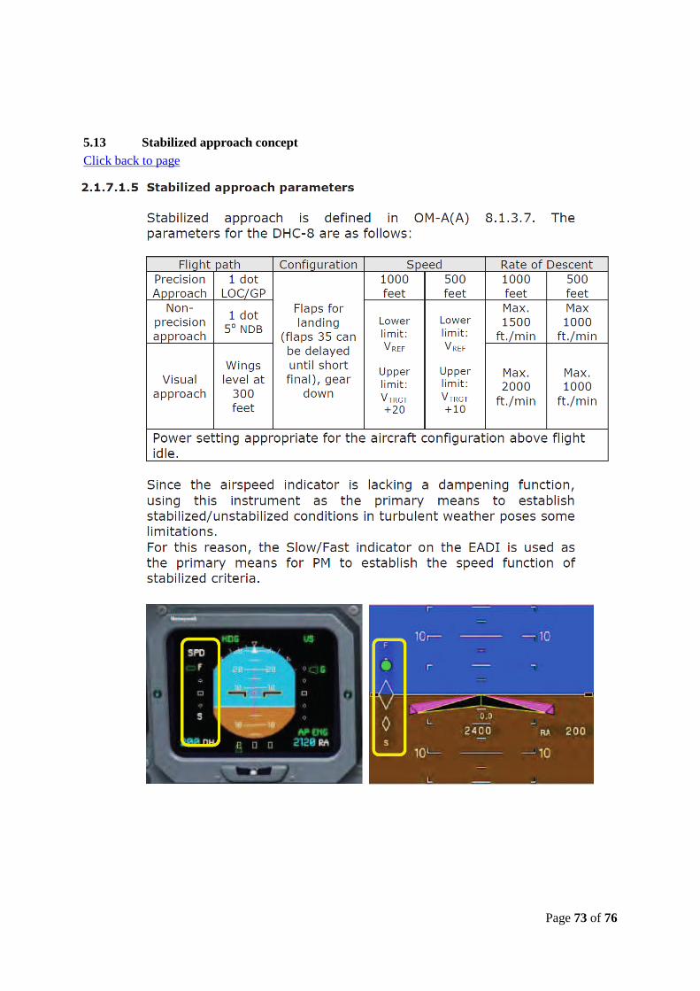
Page 73 of 76
5.13 Stabilized approach concept Click back to page

Page 74 of 76
Click back to page

Page 75 of 76
5.14 Landing on contaminated or slippery runways Click back to page

Page 76 of 76
5.15 Airport operations manual - snow clearing (extracts) Click back to page 06.04.03 Snow clearing at Nuuk If a runway inspection reveals the necessity of snow clearing, snow clearing is initiated immediately and maintained as long as conditions at the movement area may impede the safety and regularity of air traffic. Supervision of potential changes of deposits on runway/apron rests at the technical services. AFIS may also inform of potential changes in the area. Snow clearance etc. will be carried out in the following order: a. Runway and taxiway and access road from the fire station b. Access road from the fire station to the taxiway c. Apron. d. Other areas ------------------------------------------------------------------------------------------------------------------------- In case when a postponement of clearance operations involves essential risk for developing into complicated situations, e.g. when fall in temperature may cause that water becomes solid ice, the aerodrome service in consultation with the works director and/or the airport manager is authorized to demand that sections of the movement area closed for traffic. The expected time of closure is reported to AFIS, who informs the airlines. -------------------------------------------------------------------------------------------------------------------------- Practical information: Time consumption - sweeping of runway: 40 minutes Time consumption - sweeping of apron: 45 minutes