service crane mod. 3304. - maxiliftcobracranes.com crane mod. 3304. use and ... and applied on the...
TRANSCRIPT

42
SERVICE CRANE Mod. 3304.USE AND MAINTENANCE MANUAL
Code MD.0.051Rev 0Edition 07/97

43
OPTIONALS SUPPLIED ALONG WITH THE CRANEDescription YES NO
Oil tank
Outrigger beam - (mechanical jack)
Outrigger beam - (hydraulic jack)
The table has to be filled carefully with the above option when purchased
PRELIMINARY INFORMATION
Operator’s and maintenance manual of MAXILIFT COBRA 3304 SERVICE CRANE
Manual code: MD.0.051
This manual is valid starting from serial no: 3012
Manufacturer: NEXT HYDRAULICS S.r.l.
Via Costituzione 25, I 42028 POVIGLIO
In this booklet the word “Manufacturer” is referred to “NEXT HYDRAULICS S.r.l.”
List of documentation supplied along with the CRANE:
• Operator’s and maintenance manual (for the end user)
SERIAL NO:..............................................................
YEAR OF MANUFACTURING:.................................
ATTENTION
Always carefully read this manual before operating the crane. Most of the accidents occurred duringoperations are caused by the omission of elementary precautions and non fulfillment of the safety instruc-tions. Many accidents can be avoided when their causes are well known and the relevant adequatecounter measures are previously taken.

INDEX
1 FOREWORD ................................................................................................. PAGE 11.1 Summary ......................................................................................................................................................... “ 11.2 Remarks .......................................................................................................................................................... “ 11.3 Manual revision ............................................................................................................................................... “ 2
2 HOW TO CONSULT THE MANUAL .................................................................... “ 22.1 Instructions ...................................................................................................................................................... “ 2
3 CRANE IDENTIFICATION ................................................................................... “ 33.1 Versions and optional available ...................................................................................................................... “ 33.2 CRANE identification data .............................................................................................................................. “ 3
4 CRANE USAGE AND LIMITS OF APPLICATIONS.............................................. “ 44.1 CRANE classification and proper usage ........................................................................................................ “ 44.2 Improper usage ............................................................................................................................................... “ 44.3 CRANE operator’s training ............................................................................................................................. “ 4
5 SAFETY RULES .................................................................................................. “ 65.1 Rules concerning people ................................................................................................................................ “ 65.2 Rules concerning the crane ............................................................................................................................ “ 65.3 Rules for the correct positioning of the crane ................................................................................................. “ 75.3.1 Choice of the crane operating place pressure on the ground ........................................................................ “ 75.3.2 Safety distance from trenches and slopes ..................................................................................................... “ 75.3.3 Safety distance from electrical power lines .................................................................................................... “ 85.3.4 Crane and load ground connection ................................................................................................................ “ 85.3.5 Influence of the wind on the crane operation ................................................................................................. “ 105.4 Rules concerning safety in the traffic ............................................................................................................. “ 105.5 General rules on winch operations ................................................................................................................. “ 115.5.1 Winch system operation ................................................................................................................................. “ 115.5.2 Operator safety tips ........................................................................................................................................ “ 115.5.3 General rules when operating winch .............................................................................................................. “ 115.6 WIRE ROPE ................................................................................................................................................... “ 125.6.1 General ........................................................................................................................................................... “ 125.6.2 Wire rope precautions ..................................................................................................................................... “ 12
6 DESCRIPTION OF THE CRANE ......................................................................... “ 136.1 Model: 3304 H ................................................................................................................................................. “ 136.2 Model: 3304 E - 12V/24V ................................................................................................................................ “ 146.3 Controls description ........................................................................................................................................ “ 156.3.1 Description of shunt board .............................................................................................................................. “ 156.3.2 Description of control box ............................................................................................................................... “ 166.4 Safety devices ................................................................................................................................................. “ 166.4.1 Safety devices installed .................................................................................................................................. “ 166.4.2 Load limiting device ........................................................................................................................................ “ 176.4.3 Relief valve ...................................................................................................................................................... “ 176.4.4 Pilot operated holding valves .......................................................................................................................... “ 176.4.5 Safety devices’sealing ..................................................................................................................................... “ 17
7 OPERATING INSTRUCTIONS............................................................................. “ 187.1 General attentions ........................................................................................................................................... “ 187.2 Stabilizing the truck ......................................................................................................................................... “ 197.3 Opening the crane .......................................................................................................................................... “ 217.4 Closing the crane ............................................................................................................................................ “ 21
I

7.5 Winch system operation ........................................................................................................................ Page 217.6 Before starting traveling on road .................................................................................................................. “ 217.7 Main errors occurring when operating the crane .......................................................................................... “ 217.8 Standard hand signals .................................................................................................................................. “ 22
8 PUTTING THE CRANE INTO SERVICE ............................................................ “ 238.1 Ten rules for the perfect crane operator ....................................................................................................... “ 238.2 Daily check list .............................................................................................................................................. “ 238.3 Safety tips for crane starting in cold climates .............................................................................................. “ 238.4 Crane protection and storage ....................................................................................................................... “ 238.4.1 Short shutdowns ........................................................................................................................................... “ 238.4.2 Long shutdowns ............................................................................................................................................ “ 24
9 MAINTENANCE ................................................................................................. “ 259.1 Warnings ....................................................................................................................................................... “ 259.2 Maintenance prescriptions ............................................................................................................................ “ 259.3 Maintenance schedule .................................................................................................................................. “ 269.3.1 Daily checking ............................................................................................................................................... “ 269.3.2 Monthly checking .......................................................................................................................................... “ 279.3.3 Checking every six months ........................................................................................................................... “ 279.3.4 Others ........................................................................................................................................................... “ 279.4 Crane servicing ............................................................................................................................................. “ 289.4.1 Oil level checking .......................................................................................................................................... “ 289.4.2 Oil change ..................................................................................................................................................... “ 289.4.3 Oil filter replacement ..................................................................................................................................... “ 289.4.4 Wormgear assembly control ......................................................................................................................... “ 299.4.5 Greasing the hydraulic boom sections ......................................................................................................... “ 299.4.6 Wear pads check and replacement .............................................................................................................. “ 299.5 Greases and oils reference table .................................................................................................................. “ 309.6 Wire rope ...................................................................................................................................................... “ 319.6.1 Wire rope inspection ..................................................................................................................................... “ 319.6.2 Rope replacement ......................................................................................................................................... “ 319.6.3 Wire rope lubrication ..................................................................................................................................... “ 329.7 Possible faults and relevant remedies .......................................................................................................... “ 33
10 TECHNICAL DATA ............................................................................................. “ 35Overall dimension ..........................................................................................................................................Performances .................................................................................................................................................Load chart table .............................................................................................................................................
11 WIRING AND HYDRAULIC DIAGRAMS............................................................ “ 3711.1 Wiring diagrams ........................................................................................................................................... “ 3711.1.1 3304 H wiring diagram.................................................................................................................................. “ 3711.1.2 3304 E - 12V/24V wiring diagram ................................................................................................................ “ 3811.2 Hydraulic diagrams ....................................................................................................................................... “ 3911.2.1 Hydraulic diagram 3304 H ............................................................................................................................ “ 3911.2.2 Hydraulic diagram 3304 E ............................................................................................................................ “ 40
II

1
1 FOREWORD
1.1 SUMMARYThis manual is divided into chapters to make its consultation easier.
Chapter 1: Includes summary and a short introduction.Chapter 2: Explains how to consult the manual.Chapter 3: Crane identification data.Chapter 4: Limits of crane operation and usage.Chapter 5: Safety rules.Chapter 6: Description of the crane, safety devices and controls.Chapter 7: Description of operation and usage tips.Chapter 8: Crane starting up and storage.Chapter 9: Essential crane maintenance instructions. Additional instructions can be included in the
truck maintenance manual.Chapter 10: Includes the crane technical data, load charts and diagrams, list of main characteristics.Chapter 11: Wiring and hydraulic diagrams
1.2 REMARKSMany thanks for the preference kindly given to our product. Please remember that the servicing instructionsand the load charts hereby reported and applied on the crane are an essential part of the crane supply itself.They are mainly intended for the crane operator and include all necessary information on the admittable andpermissible field of usage for a safe operation. Anyway, these instructions are not a training manual forbeginners or unskilled operators, it must be stressed that as a fundamental presupposition only skilled andprofessional crane operators are allowed to work with the crane.The crane operator is directly responsible for the state of the crane and for every crane operation. When thetraining is hurried and full of gaps, this is the origin of many accidents. This manual gives the guidelines fora correct, safe usage of the crane and its rational maintenance. When daily and constantly applied, theseguidelines ensure long service life with minimum maintenance costs, high performance of the crane andgood commercial value after years. Moreover, most of the frequent accidents during operation and servicingare avoided. Once this manual has been read carefully, keep it in good conditions and quickly availableclose to the crane.If a technical assistance is required please apply to the nearest authorized installer.
ATTENTIONAs far as safety is concerned it is strongly recommended to carefully read the safety tips of thechapter, SAFETY RULES.
ATTENTIONShould some or any part of this manual be not clear, please contact the Manufacturer.
IMPORTANTWhen receiving this manual, check if all the data are correct. Inform the Manufacturer if so-mething is found wrong.

2
NOTEThe table on the back of the front page has to be filled at customer’s care. It contains all the ne-cessary data required when calling our Technical Service.A copy of this manual is supplied along with every crane. Data, descriptions and pictures of this manual arenot binding. The Manufacturer reserves the right to change at any time all the items, components and partsdeemed to be necessary for product improvement or commercial or production needs. This right is keptwithout obligeance of quick updating of this manual. Fundamental data, performances and characteristicsof the product will be maintained.
1.3 MANUAL REVISIONShould be necessary to carry some modification on the crane, they must be authorized by the Manufacturerwhich also takes the commitment of manual updating. Revised or added pages will be mailed to the Custo-mer and shall be inserted in the manual at his care and cost.
2 HOW TO CONSULT THE MANUAL2.1 INSTRUCTIONSAlways carefully read this manual before operating the crane. In this manual the following symbols are used:
DANGERReferred to dangers related to the described activity, when the safety of people is concerned.
ATTENTIONReferred to dangers related to the described activity, mainly when the safety of things is concer-ned (for instance, damage of the load or of the crane).
IMPORTANTReferred to information or integration on crane operation.
NOTEUsed to draw your attention on information or suggestions to make easier the crane usage forthe operator.The symbols and marks are completed with notices stating the dangers, their nature, the avoidance actionsto be taken and tips to be followed.
DANGERIn this manual the crane is shown in many pictures with its panels or covers removed for a better evidence.It is forbidden to use and operate the crane with panels, covers and other safety devices removed.
!
!

3
3 CRANE IDENTIFICATION3.1 VERSIONS AND OPTIONS AVAILABLEThe service instructions written on this manual are referred to the CRANE MAXILIFT COBRA 3304. Thismodel is supplied in 3 versions, the hydraulic circuit can be fed by a pump driven by a power-take-off on thetruck gearbox, or alternatively by a DC hydraulic power pack connected to the truck battery. So, whenordering, one or more of the following versions are to be specified:
3304 E 12V DC single boom hydraulic section, electro-hydr.version3304 E 24V DC single boom hydraulic section, electro-hydr.version3304 H single boom hydraulic section, PTO version
The following options are available for the above versions:
Type of optional Available on models
Oil tank (only for H version)
Outrigger beam - (mechanical Jack) All
Outrigger beam - (hydraulic jach) All
3.2 CRANE IDENTIFICATION DATAEvery crane is identified by its serial number and name of the model written on the plate riveted on the crane.The same data are also punched on the crane column.
Data plate description Colum punchinga) Crane model g) Crane modelb) Serial number h) Serial numberc) Year of manufacturingd) Lifting classe) max SWLf) Approval number
ATTENTIONIt is strictly forbidden to change, erase, modify the data written on the plate and punched on thecolumn.
Fig. 1

4
4 CRANE USAGE AND LIMITS OF APPLICATIONS4.1 CRANE CLASSIFICATION AND PROPER USAGEThe machine is an hydraulic truck crane for hook service. It can also be used for the same purpose from astatic mounting. The lifting capacity is 1.8 ton-meter (13,000 ft. lbs.), making it especially suitable for instal-lation on light truck.The crane is classified in class H2-B3 according to DIN 15018 standards, and must be used accordingly,that is: trucks loading/unloading, hook service.
4.2 IMPROPER USAGEIt is forbidden:• To use the crane in different operations from those it has been designed and built for. (see abovepoint 4.1).• To use the crane with attachment like: grabs, clamshells, magnets and so on.• Pulling loads with crane in horizontal position.• To operate the crane with procedures different from those described in this manual, or using componen
ts and attachments not approved when the crane was designed.• Non observance of the established maintenance programs.• Non observance of safety rules.• To make modifications involving crane components or parameters related to the working cycle.• The unauthorized use of captive spare parts and components not specifically approved by the Manufac
turer.• To carry out modifications or structural interventions without the approval of the Manufacturer.• To operate the crane out of the admittable range of temperatures:• -30° C/ +50° C (-22 °F/ + 122 °F).
Any of the above mentioned improper usages or non observance will cause:• immediate cancellation of the Manufacturer Warranty• cancellation of Manufacturer liability for damage of people, animals, things.
ATTENTIONThe improper usage can damage the crane and subsequently result in dangerous situations forthe staff entitled to its operation.
4.3 CRANE OPERATOR’S TRAININGThe crane must be operated only by skilled people trained for this purpose.This people will be asked for:• a basic technical education and a working experience in the mechanical, hydraulic and electrical field;• a technical knowledge of cranes operation, covering all the points, especially the load charts and the
truck stability against tipping over;• practical knowledge of slings usage and precautions when moving the loads;• complete knowledge of all the operations and motions to be executed with the crane; competent and
qualified personnel of the authorized workshop which has installed the crane will take care ofthis;
• complete reading and understanding of this manual;• complete knowledge and understanding of safety and risk avoidance regulations;• Vision of at least 20/30 Snellen in one eye and 20/50 in the other, with or without the aid of corrective
lenses;

5
• normal depth perception and field of vision (peripheral);• ability to distinguish colors if color recognition or differentiation is, required for safe operation;• adequate hearing, with or without a hearing aid;• sufficient strength, endurance, agility and coordination to meet equipment operation demands;• emotionally stable;• not subject to seizures, loss of physical control, dizziness or have physical limitations which could impair
the ability to safety operate the crane.

6
5 SAFETY RULES5.1 RULES CONCERNING PEOPLE• Always wear the prescribed personal safety devices• Always wear approved accident-prevention clothing such as: protective helmets, anti-slip shoes, protec
tive gloves, antinoise headphones, protective glasses, reflective jackets with breathing apparatus. Consult your employer regarding current safety regulations and accident-prevention equipment.
• Do not wear ring, wristwatches, jewelry, loose-fitting or hanging clothing such as ties, torn garments,scarves, unbuttoned ja-ckets or unzipped overalls, which could get caught up in the moving parts of thecrane.
• Keep quickly and readily available on the truck a first-aid box and a fire extinguisher. The fire extinguisher must always be kept charged and has to be used according to current regulations.
5.2 RULES CONCERNING THE CRANE• The Manufacturer is not liable for accidents occurred during the usage of the crane caused by non
fulfillment from the opera tor’s side of current rules, laws and regulations.• The crane is designed to be used within the -30°/+50° (-22 °F/ +122 °F) temperature range and has to be
operated only in this range. The manufacturer is not liable for accidents occurred during the usage ofthe crane outside this temperature range.
• Carefully read the Operator’s and maintenance manual before starting up, using, servicing or doing anything on the crane.
• Read and follow all the safety instruction plates applied on the crane before starting up, using, servicingor doing anything on the crane.
• Do not use controls and hoses as handholds: these parts move and cannot provide stable support.Furthermore, a control mistakenly moving can accidentally set the crane in motion.
• The operator’s control desk must always be kept clean from oil, grease, mud, snow to avoid accidentsdue to slippery surface.
• The safety instruction plates, notices, load charts and any other sticker applied on The crane must bekept readable and in good conditions. If necessary, replace them. The position of these plates is shownin the following picture.
1R
1L
2
3
4
8
7
6 6
2
Fig. 2
7
5

7
5.3 RULES FOR THE CORRECT POSITIONING OF THE CRANE
5.3.1Choice of crane operating place pressure on the ground• Carefully choose the place where lowering and put into action the stabilizers of the crane outriggers.
The most important thing is the capacity of the ground to bear the pressure produced by the outriggers.• Make sure that the outriggers working area is free from underground piping, tunnels, holes.• The positioning must be carried out so as to operate the crane with the shortest outreach possible and
without any obstacle in the working area.• Never move the crane from its rest position without stabilizing the truck.• The outriggers reaction is transmitted to the ground by steel pads. When this pressure exceed the
maximum admittable pressure value of the ground, the surface of their bearing area must be increasedby means of additional plates of firm material (i.e. wooden plates). The outriggers pads must work in themiddle of the additional plates. The required bearing surface can be easily calculated as followswhen the outrigger’s reaction and the admittable pressure on the ground are known. Outrigger’sreaction: look at the plate applied on the outrigger jack. Admittable pressure on various types of soils:look at the following table for indicative values.
Bearing pressure calculationWhen: Then:t = outrigger’s reaction (tons) (US ton) p = bearing pressure on ground (daN/cm2) (lbs./Sq.in.)A = bearing plate surface (cm2) (sq. in.)
p = (1000 • t) : A (metric)p = (2000 • t) : A (U.S.A.)
ATTENTION
In case of doubts on the ground carrying capacity, make a hardness test of the ground.Always level the crane acting on outriggers with reference to the level indicator fitted on the truck. Maximumadmittable angle is 3°.
5.3.2Safety distance from trencher and slopesThe crane must be positioned sufficiently far away from trenches or slopes. The safety distance dependsalso on the soil, if the slopes or trenches are not sustained. Rule of the thumb: (look at the following picture)
SOIL ADMITTABLE PRESSURE(daN/cm2) (lbs./sq.in.)
Dumped, non compacted soi 0.0/1.0 0,0/14natural, virgin soil:-mud, marshland, peat 0.0 0,0incoherent artificially compacted soils:-fine and medium size sand 1.5 21-large size sand, gravel 2.0 28natural coherent terrain:-doughy 0.0 0,0-soft. 0.4 6-stiff 1.0 14-demi-solid 2.0 28-solid 4.0 56rock, not altered by athmospheric agents, well stratified and slightly cracked:-closed stratified 15.0 213-solid stratified, pillar-like 30.0 426

8
Fig. 3
!
• for brought-back or crumbling terrain safety distance (a) must be double of the slopes’ depth that is:a = 2 • b
• for compacted, not crumbling terrain safety distance (a) must be equal to the slopes’ depth, that is:a = 1 • b
Distance to be measured from point ©Max. reaction on the ground varies according to the vehicle where the crane is installed.
IMPORTANTThe installer must calculate this max. reaction on the ground and applied the value on the ou-trigger jacks.
5.3.3Safety distance from electrical power linesAlways keep a sufficient safety distance when you cannot avoid having electric power lines in the workingarea of the crane. Special care must be taken when the power lines have not been disconnected by expe-rienced people, or when the lines status is unknown.
Voltage (V) minimum distance(m) (ft)
up to 1000 v 1 4from 1 kV to 110 kV 3 10from 110 kV to 220 kV 4 13from 220 kV to 380 kV 5 16
DANGERAlways keep a sufficient safety distance from electric power lines. Follow present law regula-tions. When the voltage of the lines is unknown keep a minimum safety distance of at least5m (20 ft.)
5.3.4Crane and load ground connectionThe crane can be electrostatically charged, especially when the additional bearing plates are made of insu-lating materials (wood, plastics) It has to be noted that, even when the crane has been connected to ground,the load can be loaded electrostatically charged, because the rope pulleys or the slings and ropes used tolift the load are made of insulating materials.
DANGERAlways connect to ground both the crane and its load before starting operations
!

9
Grounding is especially required when:• working close to electric power lines;• working nearby powerful broadcasting plants such as radio, T.V., an so on• working nearby electricity plants where high frequency is involved• when a storm is approaching
Crane ground connection
DANGERelectrocution hazard
While grounding the crane, carefully follow the below mentioned instructions, in order to avoidelectrocution hazard
In order to avoid electrocution hazard the following tips must be followed:• drive a metal rod, roughly 1.5 meter long, (5 ft.) in the ground, at least 1 meter (4 ft.) deep• connect a power cable of minimum 16 mm2 (0,025 sq. in.) cross section to the former rod. This linkage
must be made with a hose clamp or a vice.• moisten the ground all around the rod to improve conductivity.
NOTEArrange the linkage for ground connection and the relevant symbol• connect the remaining end of the cable with the point of connection indicated en on the crane base.
DANGERelectrocution hazard
The ground cable must be connected only on the indicated point on the crane base. Avoid anylinkage to screwed on parts of the crane, such as valves, cover plates, gearboxes, etc.
DANGERelectrocution hazard
Always ground the crane perfectly.
Load ground connectionIn order to avoid the electrostatic charging of the load it is necessary to use:
• a metal rod having a good conductivity, with a length of 1.5 meters (5 ft.) roughly, to be driven into theground, at least 1 meter (4 ft.) deep.
• a power cable with a minimum cross section of 16 mm2 (0,025 sq. in.).• a second metal rod, having good conductivity and an insulating handle complying to the relevant safety
Regulations. This rod has to be used to touch the load.• Then connect this cable to the ground rod on one side. Moinsten the ground all around the rod toimprove conductivity.• Then connect the other side of the cable to the insulated rod. Both connections must be made using the
relevant vices or metal clamps as an alternative.
!
!

10
!
!
DANGERelectrocution hazard
Always connect in a perfect way the load and the groundBefore touching the load with your hands, always ground the load by touching it with the insulated rod.
DANGERelectrocution hazard
Always hold the rod by its insulated handle.
5.3.5 Influence of the wind on the crane operationA strong wind can overload the crane, so during operations keep under control the wind speed. Whenworking with full load, the maximum admittable wind speed is 45 km/h (28 mile/h).When this value is exceeded, any crane operation must be stopped and the crane must be brought to therest position. Since the maximum working height of the crane is reasonable, refer to the following table toevaluate the possible wind effect:
Force of the wind wind speed wind effectsBeaufort Denom. m/sec(ft./sec.) km/h (mile/h)0 calm 0 - 0.2 0-0.65 1 0.6 calm,the smoke goes straight upwards1 light 0.3 - 1.5 1-5 1-5 0.6-3 wind direction can only be seen looking at the
smoke. Wind indicators are idle2 light 1.6 - 3.3 5-11 6-11 3-7 leaves are moving,the wind can be on the face.3 light 3.4 - 5.4 11-18 12-19 7-12 leaves and small brances are moving breeze4 slow 5.5 - 7.9 18-26 20-28 12-17 dust and paper sheets are lifted up, breeze
slender, rods are moved5 strong 8 - 10.7 26-35 29-38 17-24 small waves on water surfaces breeze6 strong 10.8 - 13.8 35-45 39-49 24-30 rods are bent,it is difficult to use wind umbrella7 tight 13.9 - 17.1 45-56 50-61 30-38 the trees are moved it is difficult to wind walk
against wind8 stormy 17.2 - 20.7 56-68 62 - 74 38-46 trees’branches break.it is very difficult to walk in
open areas9 tempest 20.8 - 24.4 68-80 75 - 88 46-55 small damages to buidings (roofing tiles wind fall
down)10 violent 24.5 - 28.4 80-93 89 - 102 55-63 big damages to the buildings, trees uprooted
tempest
5.4 RULES CONCERNING SAFETY IN THE TRAFFIC- The machine is an hidraulic crane for lorries and light trucks.The installation on the vehicle must be made
in compliance with the relevant national laws and regulations.- When traveling on roads and public sites always respect the relevant national laws and regulations.
DANGERBefore traveling on roads,make sure that the crane is folded in rest position. If the crane is openor lying on vehicle’s body exceeding the overall dimensions allowwed by the highway code,it canhit bridges,electric power lines or other obstructions.-Before driving away,make sure that the lever of the pin securing the outrigger’s beam is fully locked.Accidentalslipping out of the outrigger during traveling can result in serious damages. Special care must be takenwhen driving nearby crossroads, lever-crossing and subways.
!

11
5.5 GENERAL RULES ON WINCH OPERATIONS
5.5.1 Winch system operationThe Winch is mounted at the rear of the first section boom.It has capacities totally indipendent of the rest ofthe crane and can normally pull more than the crane itself can withstand.Therefore,care must be taken toinsure that the load being lifted is within boom rating.To lift some of the heavier loads on the capacity chart,itwill be necessary to multiple-part reeve the winch block to increase the lifting capacity of the winch (thespeed is proportionately slower) and remain in the strenght limitations of the winch and wire rope.The winch load rating chart on each machine provides the information for pull limitations on the winch withvarious applicable part reevings.These ratings are based on providing the proper operating safety factor onthe wire rope supplied with the machine.Therefore,any replacement rope must meet the rope specifications for size,construction and stregth asoutlined in specification sections of this manual.
5.5.2Operator safety tips• Do not pull the load block into the boom tip.• Payout loadline before or during boom extension to avoid two-blocking.• Do not allow personnel to ride the load-line, hook or load, or any other device attached to loadline.• Keep at least three full wraps of wire rope on the winch drum at all times.• Check the winch brake for proper operation before handling the load.• Use proper multi-part reeving for the load to be lifted.• When using multi-part reeving, be sure cable is properly routed.• Know the lifting capacity of both the winch and boom. They will have different capacities. The weight of
the load must not ex-ceed the lesser capacity.• Do not drag loads with winch or boom.• Always wind loadline.under tension to assist proper spooling
5.5.3General rules when operating winch1 - Always operate the winch control to payout the loadline while extending the boom. This will maintain
clearance between the boom tip and loading hook.2 - Do not pull load block into boom tip.3 - Make certain the winch cable is not twisted or kinked and that cable is properly seated on the drum
and in the sheaves.4 - Before lifting a load, always make certain that three full wraps of rope will remain on the drum at all
times throughout the lift.5 - When lifting a load approaching the rated winch load, raise the load a few inches and return thecontrol to neutral to determine if the brake is working properly.6 - Do not drag loads in any direction with the winch.7 - Never attempt to lift loads wich are not loose and free, i.e. frozen down material or poles out ofground.8 - Maintain tension on the loadline at all times to prevent the cable from becoming twisted or improperly
seated on the winch drum or sheaves.9 - Avoid rough boom lifting and lowering manoeuvres with suspended load, in order not to cause dan-
gerous swingings of the same.10- Avoid boom extension manoeuvre under load. When moving loads near to max. rates it is rather
advisable to extend the boom without load in order to reach the vertical line of the same, and then toproceed with lifting by using the winch.

12
5.6 WIRE ROPE
5.6.1GeneralWire rope can be the weak link in crane safety. It is subjected to heavy loads, abrasion, kinking, extremeweather conditions, chemical attack and other forces which can reduce its reliability. The inspection andcare of wire rope is essential in the effort to provide for safe working conditions.
5.6.2Wire rope precautions1 - Avoid the formation of kinks. Kinks will cause severe weakness in the rope. No corrections are availa
ble for kinked rope.2 - Do not drag wire rope over a non-rotating support such as a non-functioning sheave. Severe abrasion
caused to outer wire strands will result from friction.3 - Do not use worn sheaves or flat grooved sheaves. They do not provide support to the full radius of the
rope. Flattening and distortion will result.4 - Do not use nicked or otherwise broken sheaves. Necks and cracks in sheaves will cut the wire rope.5 - Evenly wrap wire rope onto the drum. Uneveness will cause crusking and/or crimping of the rope.6 - Select replacement wire rope to match the capacity and use of the crane. The crane was originally
equipped with appropriate wire rope.7 - Do not expose the rope to corrosive chemicals.8 - Lubricate the rope frequently to reduce friction and help prevent corrosion.
Fig. 4

13
6 DESCRIPTION OF THE CRANE6.1 MODEL 3304 HItem Description
1 Slewing system2 Slewing motor3 Column4 Main boom5 Boom hoist cylinder6 First hydraulic boom section7 Second mechanical boom section8 Telescope cylinder910 Control valve11 Electric shunt board12 Remote control box13 Winch14 Travelling block15 Oil tank - (only for H version ) OPTIONAL16 Outrigger beam - (mechanical jack) OPTIONAL17 Outrigger beam - (hydraulic jack) OPTIONAL
Fig. 5
12
3
4
5
67
8
1011
13
12
14
16
17
15

14
6.2 Model 3304 E 12V/24VItem Description
1 Slewing system2 Slewing motor3 Column4 Main boom5 Boom hoist cylinder6 First hydraulic boom section7 Second mechanical boom section8 Telescope cylinder910 Control valve11 Electric shunt board12 Remote control box13 Winch14 Travelling block15 Elettro-hydraulic power pack16 Outrigger beam (mechanical jack) OPTIONAL17 Outrigger beam (hydraulic jack) OPTIONAL
Fig. 6
1 2
3
4
5
7
6
8
10
11
12
13
14
16
17
15

15
6.3 CONTROLS DESCRIPTIONThis crane is fitted with a standard cable remote control.The remote control system includes a directional electro-hydraulic unit (manifold) (A) and a electric shuntboard (B), placed inside the casing behind the column, and a remote control box.The electro-hydraulicmanifold includes an aluminium block equipped with directional electrovalves (EV..A-EV..B) (two each mou-vements), an electrovalve for speed increase connection (EV39) (provided only for PTO-driven versions),an adjustable flow divider (6), the main relief valve (5) and the dumping electrovalve (EV9) (provided only forPTO-driven versions).The electrovalves (EV9-EV3B-EV2B-EV1B-EV1A) are fitted with manual controls, to be used only in case ofemergency (remote control box or electric shunt board breakdown).Model 3304 - HFor emergency manoeuvres, pull the manual control of the electrovalve (EV9) and turn counter-clockwise,then repeat the operation with the electrovalve manual control coupled to the desired mouvement.Model 3304 - EFor emergency manoeuvres, pull the manual control of the electrovalve coupled to the desired mouvementand let the electric power pack motor run temporaly, supplying directly relevant relais by the prepared cablefrom the positive power terminal to the positive solenoid connection, momentarly replacing the existingcable. this way, the motor run until the cable disconnects itself. Keep the motor running only for the shortperiods required to carry out the emergency manoeuvres. Afterwards, restore the original connection.
6.3.1 Electric shunt boardThe shunt board includes an hermetic box containing some relais (2) with safety functions (load limitingdevice, anti two block system for winch,stop-end system on drum winch and crane arrest for operationsbelow 0 deg.), a fuse (3) with the positive feeding cable and a terminal board (4) connected to the solenoids’small cables (6) and (5). Cable (5) is available only for PTO-driven cranes.
15Fig. 7
BA
6
4
5
23
5
EV4A
EV3A
EV2A
EV1A
EV2B
EV1B
EV4B
EV3B
E 12V/24VElectro-Hydraulic version
EV39
56
EV4B
EV3B
EV2B
EV1B
EV9
EV4A
EV3A
EV2A
EV1A
PTO drivenHydraulic version

16
6.3.2 Remote Control BoxAll moving operations are carried out by the remote control box.In order to activate the control box, use ON/OFF switch (E), which gives tension to the control box, as youcan see by the green LED.Now, the following manoeuvring buttons are ready:A - slewingB - boom raisingC - boom extensionD - winch raising/loweringE - ON/OFF switch (emergency)F - double speed button
The speed increase button (F) can be pushed during each manoeuvre and can be activated or disactivatedat any moment.
6.4 SAFETY DEVICES
6.4.1Safety devices installedAll the safety devices,installed on MAXILIFT COBRA 3304 crane, are listed and described in the followingpages.
description of safety functionsThe crane is fitted with 4 standard electrohydraulic safety limitations:1) The load limiting device, which intervent each time the load mentioned on loading diagram is excee
ded and locks the crane, stopping all mouvements, except re-entry of boom extension and loweringthe load.
2) 0° working placing of the boom. The crane is fitted with a stop-end system allowing only boom liftingmanoeuvre when the position is lower than 0° (rest position)
3) Stop-end system for winch raising, which intervent in order to avoid the travelling block to hit againstthe pulley. It stops the raising of the winch rope, boom lowering and boom extension.
4) Stop-end system for winch lowering, which intervent when in thr winch drum remaining only 3 wrapsof rope and locks the lowering of the winch rope.
D
C
B
A
F
E
LED
On-Off
Fig. 8

17
ATTENTIONIt is strictly forbidden to alter or manipulate the safety devicesBefore operating the crane make sure that all the safety devices are in perfect working conditions
6.4.2Load limiting deviceThe load limiting device system locks crane functioning when pressure in the main cylinder reachs thesetting level, corresponding to the nominal crane moment.The load limiting is used in order to avoid crane overload.In lock position it is not possible to carry out any manoeuvre, except re-entry of boom extension and loweringthe load (only possible manoeuvres).In order to unlock the crane, re-entry with the boom extension until crane moment becomes lower than thatmarked on the loading diagramm, or intervent on winch lowering by putting the load on the ground.
DANGERThe load limiting device, even when in perfect working condition, cannot avoid accidents due tooperator’s maneuvering mistakes.
DANGERIt is strictly forbidden to operate the crane with its load limiting device switched off or put out ofservice or faulty.
NOTEThe load limiting device can lock at the max. main boom angle even without load.In such case, in orer to unlock the machine it is necessary to act simultaneosly both on the ex-tension re-entry and boom lowering levers.
6.4.3Relief valveThe main relief valve is on the control valve and limits the maximum working pressure.
6.4.4Pilot operated holding valvesThese valves are installed on every cylinder and will stop and lock every motion of the cylinder should anypressure loss occur. Before starting operations it is necessary to check that these valves are perfectlyworking, as follows:• lift a load and raise the boom up to an angle of 45° upwards, with the boom sections partially extended• switch the truck engine off push and pull repeatedly all the control switches: the load must remain still.
6.4.5Safety devices’ sealingSome safety devices or crane components can be sealed after setting during testing operations.Such sealing can be only removed by the manufacturer or by an authorized workshop who will carry out anew sealing after repairing according to Manufacturer’s specifications.
DANGERThe removal of sealing by non authorized personnel, or a sealing not complying to manufacturerspecifications results in an improper usage of the crane.
!
!
!

18
7 OPERATING INSTRUCTIONS7.1 GENERAL ATTENTIONSThe crane must be used exclusively by qualified and skilled operators. They must know location and func-tion of every control, instruments, indicators, lights, plate and sticker.
DANGERBefore starting operations make sure that nobody is in the working area of the crane.
• The crane must work only on flat ground.• Make sure that the truck is well braked and, if necessary, apply blocks to the tires.• Pull the outrigger’s beams out of their housing till the yellow line painted on it is completely visible, and
make sure that the safety pins on the box are perfectly hooked on the beams.• Lower the outriggers pads down to the ground. Be sure of not entirely lifting up the truck suspensions. It
is important for the truck stability that a part of the truck weight still burdens on the tires.• When swinging outrigger jacks are supplied check that it is in vertical position and with its safety pin
inserted in its housing and well secured (see picture 12).• When lowering the outrigger jacks stay away from them, to avoid crushing of feet and legs.• Never operate the crane without having checked that the outriggers are well positioned on firm ground.
If necessary, their bearing area must be increased with additional pads. The truck stability relies verymuch on the working conditions! When the ground under the outrigger pads is sinking, their bearingarea must be increased. The crane Manufacturer can supply additional plates with increased area.
• Be sure that the lifted loads are, for every outreach, not higher than those stated on the load chart.• Before operating the crane be sure that all the pinned joints and the hook pin are safely locked by their
retainers.• Lifting tackles, chains or ropes must be applied to the hook in such a way that will not damage the hook
safety latch.• Whilst swinging the boom always keep the load suspended from the ground. Dragging of the load is
forbidden.• Never stay or walk under hanging loads or within the operating radius of the crane.• Do not use the crane near electric power or telephone lines.• Never start the crane operation without signaling it in a proper way.• The load should never be lifted or carried on areas where people are passing or working. If this cannot
be avoided in any way, hese operations must be properly signaled.• Before leaving the controls, make sure that the control switches are in neutral position, the main switch
is turned off and the load is resting on the ground.• When the working area of the crane cannot be clearly seen from the operator control deck, a second
operator charged with signaling is required (see pag. 22).• Stay away from the outrigger beams when they are pulled in, to avoid crushing hazard between them
and the truck parts.• When the work is over make sure that the outriggers beam are locked in rest position and the shut-off
valves are closed. Lack of doing this may result in serious danger if these parts come out whilst travelingon road.
• The stickers and plates applied on the crane are necessary to enable a safe usage of the same. Shouldthem be no longer readable, replace them as soon as possible with new ones.
• Always disconnect the power take-off before driving away. If the truck engine turns at high revs, the PTOould be damaged.
• The operator should be someone who is familiar with type of crane and has had some experience with it.
!

19
• If the crane is accidentally hit, it has to be checked and tested from the closest authorized installerworkshop.• Check every month the state and correct functioning of all the parts subject to wear: pins, valves, hoses,
sliding pads and bushings, etc. If necessary replace with genuine spare parts.• It is absolutely forbidden to alterate the hydraulic circuit and open the safety seals. Failure to comply will
cause automatically the voiding of any warranty on the product. Valves adjustments or setting must bedone only by authorized installer workshops.
• Overheating of hydraulic oil may burn the sealing parts and alterate the oil itself. This can be caused byan excessive oil flow of the pump or by repeated stroke ends of the cylinders.
• Check that the pump supplies the control valve with the oil flow suggested in our technical specifications.
7.2 STABILIZING THE TRUCK• Bearing in mind the job to be done, the vehicle has to be positioned in the most convenient position,
stopped with the parking brake and the tires blocked.• The truck engine shall be kept idling (800/900 rpm).• The hydraulic circuit of the crane shall be activated as follows:
Cranes with pump driven by a power take-offEngage the PTO by means of the appropriate air switch (normally located in the cab), while depressingthe clutch pedal.If a mechanical coupling system is installed, the lever is behind the driving seat.Cranes on stationary mountingSwitch-on the hydraulic power pack.Cranes driven by DC power packThe DC power pack is connected with the truck battery. The connection is made turning on the ignitionswitch (Fig. 8, E) located on the remote control. The electric pump will start every time a switch of theremote control is moved. The crane can work even when the engine of the truck is off, but it is stronglyrecommended of keeping the engine idling, so the alternator can continuously charge the battery of thevehicle.
DANGERDC electric motor overheating. Keep the electric pump running for short periods to avoid itsover heating. The maximum working period of the pump depends on the pressure requestedby the maneuvers, but should never exceed 10÷15 minutes in any case, with intervals of 20min. to enable a sufficient cooling.
IMPORTANTIn cold weather and in winter it is advisable to wait a few minutes with the pump running at noload before starting to operate the crane. (only for PTO - driven cranes)
• Extend the outriggers beams, acting separately on each side of the truck. Their release is made turning180° upwards the locking handle (2) on picture 9. Pull the beam (1) on picture 9 out for a length of
approx. 20 cm (8 in.), then turn again the locking handle 180° downwards in its previous position. Pullagain out the outrigger beam, and the locking pin of the handle will automatically engage and lock thebeam when its working position is reached. Always extend fully the outrigger beams to their workingposition (i.e.: maximum opening position) to grant the maximum stability of the vehicle and safety. Alwayspull and push the outrigger beams acting on the handle (3) on picture 9 foreseen for this purpose, neverpull the hoses or piping.
!

ATTENTIONThe outrigger beams are in their working position when the yellow band existing on every beamcan be entirely seen.
• Lower to the ground the bearing pads of the outriggers jacks, one at a time, acting as follows:
Hydraulic jack (Fig. 10)Open the shut-off valve (1) to allow the lowering to ground of the cylinder’s pad and rod (2). The valve isopen when its lever is on position “A”. Operate the corresponding lever of the control valve until the padreaches the ground. Avoid to lift the truck off the ground unloading the vehicle suspension, this reducesgreatly the stability of the truck. Then, turn again the valve lever to its previous “C”closed position.
Mechanical jack (Fig. 11)Lower the pad (4) by pulling the locking pin (5) out of its housing. The telescope and the pad will come downbecause of gravity. When it is close to ground, engage again the pin in the appropriate hole, securing it withthe relevant safety retainer (6). Turn the crank handle (7) until the ground is reached, bearing in mind whatwas explained above regarding the vehicle suspension.
Swinging hydraulic jack (Fig. 12)When swinging jack are fitted, before operating the shut-off valve (1) make sure that the jack (2) is in verticalposition, with its pad (3) oriented downward, its pin (4) secured with the retainer spring (5). If not, take off thepin, turn the jack downward and then lock in the working position in the aforesaid way. Then open the valve(1) as explained in the previous page, operate the corresponding lever of the control valve and lower the padto the ground as described before. When duly positioned, close the valve (1) as described.
ATTENTIONWhen turning the swinging jack and removing its pin, be careful and hold it up, to prevent it fromfalling down because of gravity , resulting in damage or injuries.
• Repeat this sequence of operations for the outrigger jack on the other side of the truck and for everyother jack fitted on the truck. Make sure that the vehicle is level, in order to have a good stability.
Maximum allowed angle is 3°.
IMPORTANTProper leveling has to be checked by means of a level instrument fitted on the truck.
20
Fig. 12
1
2
1
2
3
A
C4
6
5
7
5
4
16
23Fig. 9 Fig. 10 Fig. 11

7.3 OPENING THE CRANE• Starting from the crane in rest position, operate the switch of „boom hoist up“ on remote control. When
the boom is roughly horizontal or in any case, higher than vehicle sides or other existing obstacles.• Then operate the switch “crane swing”, to direct the boom in the desired direction.• Then operate the switch “boom section extend” until the hook has reached the required position.
7.4 CLOSING THE CRANEClosing the crane into rest position is performed by carrying out the opposite movements to those made toopen it, taking special care , at the end of the operation there are no parts protruding from the truck size.Switch off the general switch on the control board, disconnect the control board connection and save it inthe driver’s cab.
7.5 WINCH SYSTEM OPERATIONThe Winch is mounted at the rear of the first section boom. It has capacities totally independent of the restof the crane and can normally pull more than the crane itself can withstand. Therefore, care must be takento insure that the load being lifted is within boom rating. To lift some of the heavier loads on the capacitychart, it will be necessary to multiple-part reeve the winch block to increase the lifting capacity of the winch(the speed is proportionately slower) and remain in the strength limitations of the winch and wire rope.The winch load rating chart on each machine provides the information for pull limitations on the winch withvarious applicable part reevings. These ratings are based on providing the proper operating safety factor onthe wire rope supplied with the machine. Therefore, any replacement rope must meet the rope specifica-tions for size, construction and strength as outlined in specification sections of this manual.
7.6 BEFORE STARTING TRAVELING ON ROADMake sure that:• The crane is in rest position as specified on chapter 7.4.• The main switch is turned off.• The control board connection has been taken off the remote control and put in its box in the driver’s cab.• The outriggers jacks are fully retracted, their stop pins are in their housing and secured with relevant
retainers.• The manual boom sections, if installed, are secured with stop pins and safety retainers.• The locking handle of the outrigger beams, (2) on pict. 9, is safely locked in place. Unexpected
sliding out of the outriggers beams when the truck is traveling could result in serious accidents.• The lever of the shut-off valve on hydraulic jacks, see (1) in pict. 9, is in the CLOSED position.• The PTO is disconnected.• The overall dimensions of the crane in rest position are complying to regulations standard.
NOTEAlways remember that if the crane is left open on the body and it overcomes themaximum height allowed by the law, it could hit bridges and other obstructions7.7 MAIN ERRORS OCCURRING WHEN OPERATING THE CRANEBecause of lacking of care or of adequate instructions, some dangers may occur during crane operation.Most common errors are:• Slinging of loads exceeding the crane capacity: always check their actual weight not to overload the
crane or the winch. Special care has to be taken when handling big loads, when free they can remainhanging on the crane and result in damages and accidents.
21

22
• A sudden stop when lowering a load. This creates high forces of inertia on the crane structure withrelevant dangerous overload.
• Hitting the rope where the load is suspended, overload is generated.• Side pull, dragging the load on the ground. All these operations originate strong overloading forces on
the crane.• The outriggers are badly positioned or the ground is not firm: in both cases the truck tilts and could tip
over.• Working with strong wind or wind gusts• The manual boom sections are not correctly installed.• The load is not correctly slinged. So the lifting accessory used (chain, rope, etc) breaks or flips out and
the load falls down to earth. The boom, suddenly unloaded, springs back and this could result in tippingover.
• Trying to lift fixed load up(rooting of trees, raising of culverts, etc). Even if their load is smaller than thecapacity of the crane, the dynamic force created when it is suddenly stripped, may easily exceed thecapacity, and make the truck tip over.
• Swinging movements of the load. When acting on the slewing control too suddenly, the load startsswinging. Danger of overload. And boom’s breaking.
7.8 STANDARD HAND SIGNALS
Fig. 13

23
8 PUTTING THE CRANE INTO SERVICE8.1 TEN RULES FOR THE PERFECT CRANE OPERATORAlways comply with the following ten basic rules:
1 - When approaching the crane for the first time, become on familiar terms with it, executing all themanoeuvres the crane can perform during working. Carefully read all the prescriptions of this
manual and execute step by step the activities hereby described to be sure of the correct understanding.2 - This manual must always be carried in the driver’s cab along with a copy of the load chart.3 - Every operationhas to be planned with care.4 - Get all the necessary information for reaching the working site: distance, itinerary, heigth of existing tunnels, capacity of the bridges to be crossed, etc.5 - Study and plan the best way to operate the crane: soil consistence, weight and dimensions of the
loads to be lifted, heigth to be raised and necessary booms outreach. Check available room orlimitations due to the presence of buildings, obstacles, electricity power lines, etc.6 - Make sure of availability of all the necessary equipment: accident-prevention clothings, additional
bearing plates with increa sed surface area, slings, hooks, ropes and chains of certified origin andin perfect conditions.
7 - Before starting crane operations check the efficiency of the safety control devices. Never use thecrane if the correct functioning of a device is not sure.
8 - Traffic and safety laws in force must be strictly observed both when travelling on road and whenoperating the crane.
9 - The warnings of these manual referred to special dangers are to be read and observed withspecial care.10 - The safety during the crane service must be kept to the highest level carrying out a regular,constant and accurate preven tive maintenance. Repairs if necessary should never be delayed,and must be made by specialized, authorized people using only genuine spare parts.
8.2 DAILY CHECK LIST• Check the existence of oil leaks• Check the correct working of the load limiting device.• Check oil level and fill up if necessary• Check the good conditions of hoses and piping• Check the good conditions of painting and chrome plating• Check the correct working of safety valves.
8.3 SAFETY TIPS FOR CRANE STARTING IN COLD CLIMATESOnly if the crane is PTO-driven: wait for some minutes with the pump running at no load before operate anycrane movement.
8.4 CRANE PROTECTION AND STORAGE
8.4.1 Short shutdownsWash and clean the crane, lubricate all the parts provided with grease nipples and the slewing system.

24
ATTENTIONNever wash the crane with chemical products or high pressure water jets, as they can causethe detaching of the stickers water entering inside the electrical components and the slewingcase.
8.4.2 Long shutdownsSame precautions as above and, moreover:
• apply protective oil on the entire crane surface• cover the crane using a plastic curtain against rain etc.• store in a dry place, under roof• disconnect the connections to the truck battery.

25
9 MAINTENANCE
9.1 WARNINGS• Do not wear rings, wristwatches, jewelry, loose-fitting or hanging clothing such as ties, torn garments,
ordinary shoes, unbut toned jackets or un-zipped overalls, which could get caught up in the movingparts of the crane. Instead, always wear approved accident-prevention clothing such as protective
helmets, anti-slip shoes, anti-noise headphones, protective glasses, and reflective jackets with breathing apparatus. Consult your employer concerning current safety regulations and accident-prevention equipment.• Apply a clearly visible plate on the cab door or on the control valve with the notice: “crane undermaintenance. Do not start”• Do not get under any raised part of the crane, unless a safety lock support has been applied to it.• Before starting any maintenance or repair operation always install safety locking supports on anyraised part of the crane, especially the boom system.• Do not jump into or out of the machine, always use adequate steps and handrails.• The truck engine should be started in closed rooms only if well aired.• Before operating the crane make sure that nobody stays or walks in the working area.
9.2 MAINTENANCE PRESCRIPTIONS• Many damages and accidents are caused by a bad maintenance or by mistakes in the maintenance
itself. Common causes are recognized to be:leacking of oil, grease or anti-freeze liquid.dirt on crane components or assemblies.breaking of ropes or slings.safety valves, load limiting device or other safety devices out of service or not in good working
conditions.hydraulic plant in bad conditions, for instances: hoses damaged, loose hydraulic fittings, etc.
• Every maintenance work has to be carried out with care.• Do not delay repair or maintenance works on the crane.• Repair works must be assigned only to qualified, skilled people.• The recommended procedures of repair and maintenance must always be followed carefully. If necessary ask for a preventive authorization.• Before taking any part away of the crane, always switch the motor off and be sure that the pressure
in all the circuits has been discharged. See relevant manual.• Do not put the head or fingers or feet or arms or any other part of the human body into an area where
the danger of shearing or crushing exists, if the parts of the machine have not previously locked in asafe way.
• Do not use your fingers to align holes or slots: always use appropriate centering tools.• Wear protective glasses with side shields to protect your eyes when using compressed air for clea
ning the machine parts. Do not allow the pressure of the air to exceed 2 bar (29 psi).• The access steps or platforms in the workshop or where the crane is operated must be built accor
ding to current hazard avoiding regulations.• Never use petrol or thinners or other flammable liquids or detergents. Use instead authorized commercially sold cleaning products which are granted to be non-flammable and non toxic.

26
DANGERof fire or scald
It is forbidden to use naked flame as lighting device when carrying out checks or looking for le-aks in the machine.• Do not lubricate, repair or carry out settings on the crane when it is working, unless this is expressly
required in the instructions of the Operator’s/Maintenance manual.• If it is necessary to lift the crane and/or other parts, make sure that they are locked as requested from
current safety regulations• Always use approved protective clothing, safety gloves and protective glasses when using steelropes, as they produce steel splinters.• Never use the tools in a way different from the one they are meant, i. e.: pliers instead of wrenches.• The maintenance area is to be kept clean and dry. Remove immediately any trace of water or oil.• Leakage of fluid from a very small hole may be almost invisible and yet strong enough to penetrate
the skin. Before starting looking for the leaks, it is important to wear protective glasses with sideshields. Do not use your hands, use a piece of cardboard or wood to locate the source of the leak.Injuries caused by pressure fluid may result in serious infections, so it is recomended to contactimmediately a doctor.• Do not heap dirty rags with oil or grease, they may be a danger of fire. Instead, put them in a metallic
closed case.• Immediately replace any missing sticker or plate carrying a notice of danger, attention or other instructions.
IMPORTANTVarious part of the crane are manufactured with high tensile steel. Never perform any operation(welding, drilling, etc) without authorization and instructions from the manufacturer.
ATTENTIONThe crane is supplied with electrical and electronic devices installed. Always disconnect theconnections of these devices before carrying out welding or other operations with electric to-ols on the crane or on any part of the truck .
• When repair or maintenance operation is over, before putting again the machine into service, makesure that any tool or other piece has not been forgotten in places containing moving parts, or close tothem.
• The machine and its accessories has to be kept in good conditions.• Replace failed or worn components with genuine spare parts or other approved by the Manufacturer.
9.3 MAINTENANCE SCHEDULE
9.3.1 Daily checking• Check the level of hydraulic oil in the tank.• Check the hoses, the fittings and all the other components of the hydraulic system, in order to elimi
nate any possible source of oil leak.• Check that all the crane is in good condition.• Immediately repair the item or the component found to be faulty.
!

27
9.3.2 Monthly checking• Check the setting of the pressures in the hydraulic system, and integrity of the seals.• Check the absence of oil leaks.• Check integrity and tightening of crane tie rods and bolts.• Check integrity and tightening of hoses, piping and their fittings.• Check fastenings and safety devices.• Check readability of symbols on the remote control.• Check integrity of hooks, ropes, chain and all the other lifting ancillary equipment.• Check that all the identification and warning plates are still applied and readable.• Visually check all the structural components for any deformation, backlash or crack out.• Clean oil filters.• Check the oil level and lubricate accordingly to the lubricating and greasing chart.• Check the regular working of the slewing system, grease with the suggested grease the worm and
the worm gear, replace the grease brush spreader if worn.• Make a working test of the crane, with and without the load, paying attention to possible unusualnoises coming from the crane parts.• Grease the hydraulic boom sections.
9.3.3 Checking every six moths• Wash and clean the crane
ATTENTIONNever wash the crane with chemical products or high pressure water jets, as they can cause thedetaching of the stickers and water entering inside the electrical components and the slewingcase.• Check the pressure settings in the hydraulic system.• Check the absence of oil leaks.• Check integrity and tightening of crane tie rods and bolts.• Check integrity and tightening of hoses, piping and their fittings.• Check fastenings and safety devices.• Make a safety test of the hydraulic system.• Check correct working of remote control and readability of relevant symbols.• Check integrity of hooks, ropes, chain and all the other lifting ancillary equipment.• Check that the all the identification and warning plates are still applied and readable.• Visually check all the structural components to find any deformation, backlash or crack out.• Check the oil level and lubricate accordingly to the lubricating and greasing chart.• Replace the filter of the hydraulic oil.• Make a working test of the crane, with and without the load, take care of listening to strange noises
coming from the crane parts.
9.3.4 Others• Stability of unit throughout working area. Check stability procedure annualy or when any change is made tocrane or truck.

9.4 CRANE SERVICING
9.4.1 Oil level checkingThe oil level must be checked daily, with the crane in rest position and the truck on flat ground If necessarytop up with hydraulic oil. The level is checked by mean of the dipstick. (1)
9.4.2 Oil changeThe oil deteriorates during daily usage. The oil change every year is necessary to avoid damages to thehydraulic system. Take a container with a capacity of 40 liters (10 gal.) and having suitable dimensions to bepositioned under the oil drain plug. (2)
ATTENTIONIt is forbidden to pollute the environment with exhausted oil.
After the replacement, it is important to carry out a bleeding of the circuit, otherwise the air introduced in thesystem with this operation may damage the sealing parts. To do that, operate every function of the controlvalve, driving it smoothly to stroke end.Use only the oils stated in the greasing/lubricating table, or equivalent ones. (chap. 9.5)
9.4.3 Oil filter replacement• Unscrew the screws (3) holding the filter case.• Pull the case out without damaging the OR.• Loosen the nut (5) and take the cartridge (4) off.• Replace it with a new one, of the same type, and tighten the nut (5) again.• Check the seal for satisfactory condition, if not replace by new one.• Insert the filter group in its housing and tighten the relevant screws.• After a filter replacement, bleed the air off the circuit as explained on point 9.4.2.
28
Fig. 14
51
4

9.4.4 Wormgear assembly control (Fig. 15)It is important to check that the worm gear reducer has a correct axial backlash. This can be made, with thecrane at standstill, the boom in horizontal position. Pushing the boom aside on the left and on the right byhand, you can notice if the axial backlash between the wormshaft (6) and the wormgear (8) is too great. Inthis case it has to be reduced, tighten the nut (7) accordingly. Grease the gear with the suggested productand replace the grease spreader (9), if worn out.
9.4.5 Greasing the hydraulic boom sections (Fig. 16)1 - Completely extend the telescopic boom2 - Grease the lower part of the extensions by a brush3 - Grease the upper part of 1st. extension by the brush4 - Carry out 2 or 3 boom re-entry and extension idling operations in order to allow the distribution of
the grease
9.4.6 Wear pads check and replacementWear pads need to be replaced when their thickness drops under 5.5 mm (0.22 inch.)
ATTENTIONFailure to replace the wear pads whenthey have reached the above statedwear limit, can prejudice to the goodand safe operation of the crane.
29
Fig. 16
Fig. 15
8
6
9
7

30
9.5 Greases and oils reference table
BRAND TOTAL MOBIL ESSO AGIP IP BP GREASE MULTIS MOBILGREASE BEACON GR MU ATHESIA ENEGREASE
EP2 MP EP2 EP2 EP2 LR MP
GREASE MULTIS MOBILGREASE BEACOM GR MU ATHESIA ENERGREASELR MP MP EP2 EP2 EP2 EP2
HYDRAULIC AZOLLA DTE NUTO OSO HYDRUS HENERGOLOIL ZS 46• 25 H 46• 46• 46 HL 80
ZS 48* H68* 68*
GREASE WINN’S (GS-80)
• for temperate and cold climate* for hot climate
Fig. 17

31
9.6 WIRE ROPE9.6.1 WIRE ROPE INSPECTIONEach day and before use, inspect the wire rope for the following conditions:
1 - Kinking (Sharp bends) 6 - Rope diameter loss2 - Crushing 7 - Rope strand uneveness3 - Unstranding 8 - General corrosion4 - Birdcaging 9 - Broken strands5 - Core protrusion 10 - Cut strands
DANGER
Do Not open the rope for inspection. Inspect the rope daily or before use each day and also inspectthe rope eye for abrasion, corrosion and broken wires.
Inspect the wire rope monthly as follows:1 - The entire length of the rope2 - The wire rope eye
9.6.2 ROPE REPLACEMENTIt is extremely difficult to determine the exact time for replacement of wire rope since many variable factorsare involved. Proper determination of the condition of a wire rope depends upon the good judgement ofan experienced person in evaluating the remaining strength in a used rope after allowance for deteriorationdisclosed by inspection. The following reasons are sufficient justification for consideration of ropereplacement:1-Six randomly distributed broken wires in one rope lay or three broken wires in one strand in one rope lay.
!
1 - When there are either 3 broken wires in one strand or a total of sixbroken wires in all strands in any one rope lay.
2 - When flat spots on the outer wires appear and those outside wires araless than 2/3 the thickness of the unworn
3 - When there is a decrease of diameter indicating a core failure
4 - When kinking, crushing, birdcaging or other distortion occurs
5 - When there is noticeable heat damage (discoloration) of the rope byany means
6 - When the diameter is reduced from nominal size by 0.8 mm (1/32”) ormore
7 - If a broken wire protrudes or lops out from the core of the rope

32
9.6.3 WIRE ROPE LUBRICATIONWire rope is lubricated during manufacturing so the strands, and individual wires in strands, may moveand adjust as the rope meves and bends. A wire rope cannot be lubrificated sifficiently during manufactureto last its entire life. Therefore, new lubricant must be added periodically throughout the life of a rope toreplace factory lubricant which is used or lost.The surface of some ropes may become covered with dirt, rock dust, or other material during their operation.This covering can prevent field applied lubricants from properly penetrating into the rope. Therefore,these ropes should be cleaned before being lubricated.The lubricant applied should be light bodied enough to penetrate to the core of the rope. Lubricant may beapplied effictively by various methods. It may be dripped on, sprayed on, or put on by brushing, but in anycase it should be applied at a place where the rope is being bent, such as at a sheave. It shold be appliedat the top of the bend, because at that point the strands are spread by bending and are more easilypenetrated. The service life of rope will be directly proportional to the effectiveness of the method usedand amount of lubricant reaching the working parts of the rope.A proper lubrificant must reduce friction, protect against corrosion, adhere to every wire and be pliableand not crack or separate when cold and yet not drip when warm.

33
9.7 POSSIBLE FAULTS AND RELEVANT REMEDIESFault
Vibrations in hydraulic cylinder and jerkin-gs at the first manoeuvres.
Vibrations with every functions when theoil is hot.
Remedy
Perform manoeuvres without loads forsome minutes to warm the oil up.
Add hydraulic oil to the tank.
Operate the control lever carrying thecylinders to stroke end for some times inboth directions.
Cause
The temperature of the hydraulic oil is toolow.
Lacking of oil in the tank. Air in thehydraulic system.
All the crane movements are very slow,even when unloaded.
The hydraulic extension are not extendingin the right sequence.
Crane rotation not regular.
The crane does not lift the loads of theload chart table.
The crane lift the load, but cannot hold it.
Noise coming from articulation points.
The hydraulic legs does not hold underload.
Suction hose from oiltank crushed orobstructed.
The pump is drawing in air.
Bad lubrication.
Sliding pads are worn.
Sequence valve on extension cylinder hasto be adjusted.
The truck is not correctly levelled.
Worn slewing motor.
Defective pump.
Uncorrect settings of the valves.
Hydraulic cylinder sealings are worn.
Uncorrect settings of the valves.
Hydraulic cylinder sealings are worn.
Lacking of lubrication.
Defective holding valves.
Worn sealings in the stabilizer cylinder.
Replace or clean the suction hose.
Check that the relevant fittings are welltightened.
Grease the extensions.
Replace sliding pads.*
Adjust the sequence valve.*
Level the truck.
Replace slewing motor.
Replace the pump.*
Adjust valve settings.*
Replace worn sealings.*
Adjust valve settings.*
Replace worn sealings.*
Grease articulation points.
Clean or replace holding valves.*
Replace worn sealings.*
The DC electric motor does not run.
DC electric motor overheating.
The crane locks with boom lifted at endcourse.
Truck battery discharged.
Electric connections are damaged.
Burned fuses.
Motor windings are burnt.
Too long running time.
Pressure transducer not set.
Setting of general max. pressure valvetoo high.
Charge battery.
Check electrical wirings, terminals, con-nections and their integrity.
Replace fuses.
Replace the electric pump.
Running periods are to be shortened andtheir intervals to be elongated.
Disassemble the casing and move ma-nually the boom descent valve (VB2).Reduce the general max. pressure valve
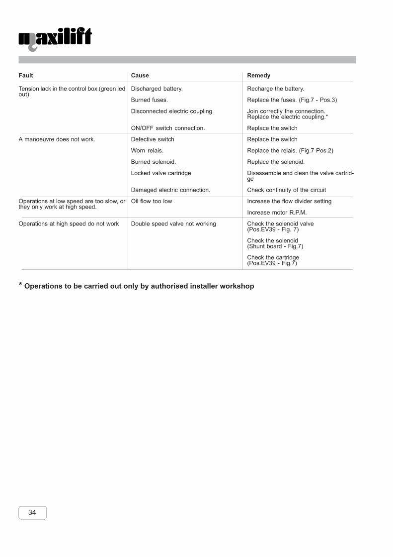
34
* Operations to be carried out only by authorised installer workshop
Fault
Tension lack in the control box (green ledout).
A manoeuvre does not work.
Operations at low speed are too slow, orthey only work at high speed.
Operations at high speed do not work
Cause
Discharged battery.
Burned fuses.
Disconnected electric coupling
ON/OFF switch connection.
Defective switch
Worn relais.
Burned solenoid.
Locked valve cartridge
Damaged electric connection.
Oil flow too low
Double speed valve not working
Remedy
Recharge the battery.
Replace the fuses. (Fig.7 - Pos.3)
Join correctly the connection.Replace the electric coupling.*
Replace the switch
Replace the switch
Replace the relais. (Fig.7 Pos.2)
Replace the solenoid.
Disassemble and clean the valve cartrid-ge
Check continuity of the circuit
Increase the flow divider setting
Increase motor R.P.M.
Check the solenoid valve(Pos.EV39 - Fig. 7)
Check the solenoid(Shunt board - Fig.7)
Check the cartridge(Pos.EV39 - Fig.7)

35
10 TECHNICAL DATA - WINCH SPECIFICATIONSSERIES 3304 STANDARD EQUIPMENTHigh speed winch with planetary gears reducer Remote control with connection and 8 m. - 26’ ft. of cableNegativ brake for winch Hydraulic system with two speedLoad limiting device Solenoid valve with manual functions (only for emergency)Rotation with worm-gear Stop-end system for winch (up and down)
TECHNICAL DATA 3304
Crane rating KNm 18Standard outreach m 4,80Slewing angle 400°Boom elevation (-5° +75°)Lifting height from base of crane m 4.80Remote control ON/OFFPump for electrical “E” 12V-24V l/min 5 - 9Pump capacity hydraul. “H” (pto) l/min 10Working pressure bar 160Crane weight Kg 300
WINCH SPECIFICATION 3304Winch pull line daN 750Pull line speed H m/min 12
E 12V-24V m/min 7 -11Rope diameter mm 7Wire rope length m 25Cable breaking strength Kg minimum 4.200
Technical data not binding
Fig. 18LOAD CAPACITIES COBRA 3304

36
TECHNICAL DATA 3304
Crane rating ft.lbs 13.000Standard outreach ft. 15’ 8”Slewing angle 400°Boom elevation (-5° +75°)Lifting height from base of crane ft. 15’ 8”Remote control ON/OFFPump for electrical “E” 12V-24V GPM 1.3 - 2.4Pump capacity hydraul. “H” (pto) GPM 2.7Working pressure psi 2280Crane weight lbs 660
WINCH SPECIFICATION 3304
Winch pull line lbs 1.650Pull line speed H ft./min 40
E 12V-24V ft./min 23- 37Rope diameter inch. 5/16”Wire rope length ft. 82Cable breaking strength lbs minimum 9.200
Technical data not binding
Fig. 19LOAD CAPACITIES COBRA 3304

37
WIRING AND HYDRAULIC DIAGRAMS11 WIRING AND HYDRAULIC DIAGRAMS11.1 WIRING DIAGRAMS
11.1.1 H version wiring diagramF1 - F2 - General fuses RPM+RPM1 - Pressure switch solenoidFV - Snatch block stop end system E39 - Double speed magnetRV1+RV2 - Stop end system solenoid FV RS - Pressure switch releasing solenoidE1A - Clockwise rotation magnet CNE 16P F - Female connectionE1B - Coutner clockwise rotation magnet F3 - F4 - Limit switch fusesE2A - Boom raising magnetE2B - Boom lowering magnet CONTROL BOXE3A - Boom extension magnet IP - General switchE3B - Boom re-entry magnet S1 - Rotation selectorE4A - Winch lowering magnet S2 - Boom joint selectorE4B - Winch lifting magnet S3 - Boom extension selectorFA - Winch lowering stop end system S4 - Winch selectorFB - Boom lowering stop end system PR - Double speed buttonR9 - Control solenoid (venting) R - ResistanceE9 - Electrical magnet (venting) LP - Led ( tension )PM - Pressure switch solenoid D - Diode
CNE 16P M - Male connection
Fig. 20

38
11.1.2 E 12V/24V version wiring diagramF1 - F2 - General fuses RPM+RPM1 - Pressure switch solenoidFV - Snatch block stop end system RS - Pressure switch releasing colenoidRV1+RV2 - Stop end system solenoid FV CNE 16P F - Female connectionE1A - Clockwise rotation magnet REM - Motor relaisE1B - Coutner clockwise rotation magnet F3 - F4 - Limit switch fusesE2A - Boom raising magnetE2B - Boom lowering magnet CONTROL BOXE3A - Boom extension magnet IP - General switchE3B - Boom re-entry magnet S1 - Rotation selectorE4A - Winch lowering magnet S2 - Boom joint selectorE4B - Winch lifting magnet S3 - Boom extension selectorFA - Winch lowering stop end system S4 - Winch selectorFB - Boom lowering stop end system PR - Double speed buttonR9 - Control solenoid (venting) R - ResistanceEM - Electric motor LP - Led ( tension )PM - Pressure switch solenoid D - Diode
CNE 16P M - Male connection
Fig. 21

39
11.2 HYDRAULIC DIAGRAMS
11.2.1 Hydraulic diagram for H version1 Pump2 Electrohydraulic unit3 Rotation motor4 Lifting cylinder5 Overcenter valve6 Pressure switch78 Extension cylinder910 Sequence valve11 Oil filter12 Oil tank1314 Winch motor
Fig. 22

40
11.2.2 Hydraulic diagram for E 12V/24V version1 Pump2 Electrohydraulic unit3 Rotation motor4 Lifting cylinder5 Overcenter valve6 Pressure switch78 Cylinder9 Overcenter valve1011 Oil filter12 Oil tank1314 Winch motor
Fig. 23

NOTES
NEXT HYDRAULICS S.r.l.Via della Costituzione, 25 Poviglio (RE) - ITALY
Tel. 0522/960707 - Fax 0522/967197
Name of the installer (person)
Name of the authorized installer workshop
Address
City Province State
Tel number. Date
Reproduction and distribution are forbidden according to law without written permission in writing fromNext Hydraulics S.r.l.
COPYRIGHT BY NEXT HYDRAULICS S.r.l.Layout and pubblication by “STM Studio Tecnico Associato”

NEXT HYDRAULIC S.r.l.Via della Costituzione, 25
42028 Poviglio (Reggio E.) -ItalyTel. 0522/960707 - Fax 0522/967197