service manual - canon globaldownloads.canon.com/bisg2017/manuals/accessories/super_g3_fax... ·...
TRANSCRIPT

SERVICE MANUAL
COPYRIGHT © 2016 CANON INC. CANON Super G3 Fax Board-AU1 / 2nd Line Fax Board-AU1 Rev. 1 PRINTED IN U.S.A.
October 14, 2016 Rev. 1
Super G3 Fax Board-AU1
Super G3 2nd Line Fax Board-AU1

IntroductionImportant Notices
ApplicationThis manual has been issued by Canon Inc. for qualified persons to learn technical theory, installation, maintenance, and repairof products.This manual covers all localities where the products are sold. For this reason, there may be information in this manual that doesnot apply to your locality.
CorrectionsThis manual may contain technical inaccuracies or typographical errors due to improvements or changes in products.When changes occur in applicable products or in the contents of this manual, Canon will release technical information as theneed arises. In the event of major changes in the contents of this manual over a long or short period, Canon will issue a newedition of this manual.
The following paragraph does not apply to any countries where such provisions are inconsistent with local law.
TrademarksThe product names and company names used in this manual are the registered trademarks of the individual companies.
CopyrightThis manual is copyrighted with all rights reserved. Under the copyright laws, this manual may not be copied, reproduced ortranslated into another language, in whole or in part, without the consent of Canon Inc.Copyright CANON INC. 2016
CautionUse of this manual should be strictly supervised to avoid disclosure of confidential information.
Explanation of SymbolsThe following symbols are used throughout this Service Manual.
Symbols Explanation Symbols ExplanationCheck.
1x
Remove the claw.
Check visually.
1x
Insert the claw.
Check a sound. Push the part.
Introduction

Symbols Explanation Symbols Explanation
1x
Disconnect the connector. Connect the power cable.
1x
Connect the connector. Disconnect the power cable.
1x
Remove the cable/wire from thecable guide or wire saddle.
Turn on the power.
1x
Install the cable/wire to the cableguide or wire saddle.
Turn off the power.
1x
Remove the screw.
1x
Loosen the screw.
1x
Install the screw.
1x
Tighten the screw.
Cleaning is needed. Measurement is needed.
The following rules apply throughout this Service Manual:1. Each chapter contains sections explaining the purpose of specific functions and the relationship between electrical and
mechanical systems with reference to the timing of operation.In the diagrams, represents the path of mechanical drive; where a signal name accompanies the symbol, the arrow
indicates the direction of the electric signal.The expression "turn on the power" means flipping on the power switch, closing the front door, and closing the delivery unitdoor, which results in supplying the machine with power.
2. In the digital circuits, '1' is used to indicate that the voltage level of a given signal is "High", while '0' is used to indicate "Low".(The voltage value, however, differs from circuit to circuit.) In addition, the asterisk (*) as in "DRMD*" indicates that the DRMDsignal goes on when '0'.In practically all cases, the internal mechanisms of a microprocessor cannot be checked in the field. Therefore, the operationsof the microprocessors used in the machines are not discussed: they are explained in terms of from sensors to the input ofthe DC controller PCB and from the output of the DC controller PCB to the loads.
The descriptions in this Service Manual are subject to change without notice for product improvement or other purposes, andmajor changes will be communicated in the form of Service Information bulletins.All service persons are expected to have a good understanding of the contents of this Service Manual and all relevant ServiceInformation bulletins and be able to identify and isolate faults in the machine.
Introduction

ContentsSafety Precautions...............................................................................................1
Notes Before it Works Serving............................................................................................................ 2Points to Note at Cleaning...................................................................................................................2Notes on Assembly/Disassembly........................................................................................................2
1. Product Overview.............................................................................................3Specifications...................................................................................................................................... 4
2. Technology....................................................................................................... 5Basic Construction.............................................................................................................................. 6
Overview.............................................................................................................................................. 6Controls...............................................................................................................................................7
Fax Communication Control...................................................................................................................7
3. Disassembly/Assembly................................................................................... 8Parts List............................................................................................................................................. 9
Power Unit System................................................................................................................................9
4. Error/Jam/Alarm.............................................................................................10Overview........................................................................................................................................... 11
How to View Error Codes.....................................................................................................................11User error codes................................................................................................................................12Service error codes........................................................................................................................... 13
5. Service Mode..................................................................................................16Outline...............................................................................................................................................17
Configuration of the Service Mode........................................................................................................17Operation method............................................................................................................................... 17Menu List............................................................................................................................................19
Setting of Bit Switch (SSSW)............................................................................................................ 21Bit Switch Composition........................................................................................................................21
Setting of Menu Switch (MENU)........................................................................................................31Configuration of Menu Switches........................................................................................................... 31
Setting of Numeric Parameter (NUMERIC Param.).......................................................................... 33Configuration of Numeric Parameters................................................................................................... 33
Setting of Destination (TYPE)........................................................................................................... 36Overview............................................................................................................................................ 36
Setting of Printer Functions (PRINTER)............................................................................................37Setting of Bit Switch (SSSW)............................................................................................................... 37Setting of Numeric Parameter (NUMERIC Param.)................................................................................38
IPFAX Setting....................................................................................................................................40IPFAX................................................................................................................................................ 40
Contents
i

Initialization of Set Value (CLEAR)....................................................................................................41Overview............................................................................................................................................ 41
Test Mode (TEST).............................................................................................................................42Outline............................................................................................................................................... 42MODEM Test......................................................................................................................................43Function Test......................................................................................................................................45
Service Report (REPORT)................................................................................................................ 46System Data List.................................................................................................................................46System Dump List............................................................................................................................... 46Error Transmission Report...................................................................................................................48
6. Installation(Super G3 FAX Board-AU1)........................................................49How to Check the Installation Procedure.......................................................................................... 50
Symbols............................................................................................................................................. 50Pre-checks........................................................................................................................................ 51
Points to Note at Installation.................................................................................................................51Check Item When Turning OFF the Main Power....................................................................................51Installation Outline Drawing................................................................................................................. 51Checking the Contents........................................................................................................................ 51
Installation Procedure........................................................................................................................52Remove the Covers.............................................................................................................................52Removing the Reader Connecting Plate............................................................................................... 52Installing the Fax Unit.......................................................................................................................... 53Installing the Covers............................................................................................................................55Procedure after Work.......................................................................................................................... 57
Operation Setting.............................................................................................................................. 60Type Settings......................................................................................................................................60Basic Setting.......................................................................................................................................60Fax communication test.......................................................................................................................60
7. Installation(Super G3 2nd Line Fax Board-AU1)......................................... 61How to Check the Installation Procedure.......................................................................................... 62
Symbols............................................................................................................................................. 62Pre-checks........................................................................................................................................ 63
Points to Note at Installation.................................................................................................................63Check Item When Turning OFF the Main Power....................................................................................63Installation Outline Drawing................................................................................................................. 63Checking the Contents........................................................................................................................ 63
Installation Procedure........................................................................................................................64Remove the Covers.............................................................................................................................64Removing the Fax Unit (When the Fax Unit is installed).........................................................................64Installing the Fax Unit.......................................................................................................................... 66Installing the Covers............................................................................................................................71Procedure after Work.......................................................................................................................... 73
Checking the Operation.....................................................................................................................76Type Settings......................................................................................................................................76Basic Settings.....................................................................................................................................76FAX Communication Test.................................................................................................................... 76
Contents
ii

Safety PrecautionsNotes Before it Works Serving..............2Points to Note at Cleaning.................... 2Notes on Assembly/Disassembly..........2
Notes Before it Works Serving
• At servicing, be sure to turn off the power source according to the specified steps and disconnect the power plug.• Do not turn off the power switch (of the host machine) when downloading is under way. Turning off the main power switch
while downloading is under way can disable the machine.
Points to Note at Cleaning
When performing cleaning using organic solvent such as alcohol, be sure to check that the component of solvent is vaporizedcompletely before assembling.
Notes on Assembly/Disassembly
Follow the items below to assemble/disassemble the device.1. Disconnect the power plug to avoid any potential dangers during assembling/disassembling works.2. If not specially instructed, reverse the order of disassembly to reinstall.3. Ensure to use the right screw type (length, diameter, etc.) at the right position when assembling.4. To keep electric conduction, binding screws with washers are used to attach the grounding wire and the varistor. Ensure to
use the right screw type when assembling.5. Unless it is specially needed, do not operate the device with some parts removed.6. Never remove the paint-locked screws when disassembling.
Safety Precautions
2

Product Overview1 Specifications........................................4

Specifications
Following is a specification list.
Item DescriptionCommunication G3Line type Public Switched Telephone NetworkModulation <G3 image signal>
ITU-T V.27ter (2.4 Kbps, 4.8 Kbps)ITU-T V.29 (7.2 Kbps, 9.6 Kbps)ITU-T V.17 (TC 7.2 Kbps, TC 9.6 Kbps, 12 Kbps, 14.4 Kbps)ITU-T V.34 (2.4 Kbps, 4.8 Kbps, 7.2 Kbps, 9.6 Kbps, 12 Kbps, 14.4Kbps, 16.8 Kbps, 19.2 Kbps, 21.6 Kbps, 24 Kbps, 26.4 Kbps, 28.8Kbps, 31.2 Kbps, 33.6 Kbps)<G3 procedure signal>ITU-T V.21 No.2 (300 bps)ITU-T V.8, V.34 (300 bps)
Transmission speed 33.6 Kbps, 31.2 Kbps, 28.8 Kbps, 23.4 Kbps, 24 Kbps, 21.6 Kbps,19.2 Kbps, 16.8 Kbps, 14.4 Kbps, 12 Kbps, TC 9.6 Kbps, TC7.2Kbps, 9.6 Kbps, 7.2 Kbps, 4.8 Kbps, 2.4 Kbpsauto fallback function
Coding method JBIG, MMR, MR, MHG3-specific abridged procedure noDial tone detection yesModem IC Modem supporting V.34 standardError correction ITU-T ECMTransmission original size A3, A4, A4R, A5, A5R, B4, B5, B5R, LTR, LTRR, LGL, 11x17,
STMT, STMTRADF: double-sided originals accepted
Scanning line density Normal: 8 dot/mm x 3.85 line/mmFine: 8 dot/mm x 7.7 line/mmSuper-Fine: 8 dot/mm x 15.4 line/mmUltra-Fine: 16 dot/mm x 15.4 line/mm
Halftone 256 gradationsRecording unit maximum reception size: A3 (297 mm x 420 mm)
scanning line density: 600 dpi x 600 dpiMemory image memory (Canon Fax Standard Chart No.1): Approx. 6000
printsmemory type: Hard disk
Extension telephone connection yesAnswering machine connection noFax/Tel switch-over yesQuick Direct Transmission yesTransmission Header(Add Remote Name on Header SW)
yes
Remote reception yesPolling (F code) noMemory box yesPassword reception yesMachine telephone No. transmission yesUser abbreviation transmission yesAuto Dial Function Address Book: 1,800 destinations
(including destinations stored in one-touch buttons)Broadcasting 256 targets (maximum number of targets)
1. Product Overview
4

Technology2 Basic Construction................................ 6Controls.................................................7

Basic Construction
OverviewThis product is a Fax Unit to connect a fax line to the host machine.This product is equipped with image processing function to enable the digital multi function printer to be used as a multi functionprinter with fax, and communication function using a telephone line.A modem supporting V.34 standard recommended by ITU-T enables this product to communicate at a maximum of 33.6 kbps.A fax line can be added by adding the Super G3 2nd Line Fax Board-AU1 to the Fax Unit for 1-line (Super G3 Fax Board-AU1).
No. Name[1] G3 Fax PCB[2] Modular PCB (1-line)[3] PCB for adding G3 2nd line[4] Modular PCB (2-line)
[1]
[2]
[4]
[3]
2. Technology
6

Controls
Fax Communication ControlIn the case of the Fax Unit for 1-line, the Main Controller PCB in the host machine controls the G3 Fax PCB in the Fax Unit.In the case of the Fax Unit for 2-line, the Fax Unit itself performs fax communication control because fax control program is storedin the G3 Fax Control PCB.
FAX interface
G3 FAX PCB
Main controller
Modular PCB
FAX unitCopier
Speaker
PCB connection for the Fax Unit for 2-line
2. Technology
7

Disassembly/Assembly3Parts List............................................... 9

Parts List
Power Unit System
No. Name[1] G3 Fax PCB[2] Modular PCB (1-line)[3] PCB for adding G3 2nd line[4] Modular PCB (2-line)
[1]
[2]
[4]
[3]
NOTE:When replacing the parts, be sure to refer to the Installation Procedure and perform the reverse order of it to remove the parts.
3. Disassembly/Assembly
9

Error/Jam/Alarm4 Overview............................................. 11User error codes................................. 12Service error codes.............................13

Overview
How to View Error CodesWhen the service mode #1 SSSW SW01 Bit0 is set to "1" after installing this board, service error code is output on thecommunication management report, reception result report, and error transmission report in the event that the communication isresulted in an error.Moreover, when an error occurs, the error code can be checked by performing the following procedure.Status Monitor/Cancel > Reception > Job Log > Details
The main error codes displayed by this board are described as a list in this manual.For causes and remedies for other error codes, refer to the "G3/G4 Facsimile Error Code Service Handbook (revised edition 2)"(document number: HY8-22A6-020) provided as a separate volume.The remedies with this board when a service error code occurs are shown below.
• Increase the transmission levelSet -8 (dBm) for service mode #2 MENU parameter No.007.
• Decrease the transmission levelSet -15 (dBm) for service mode #2 MENU parameter No.007.
• EPT (Echo Protect Tone)Change the setting of service mode #1 SSSW SW03 Bit1.Bit 1-> 1: Send EPT.-> 0: Not send EPT.
• Adjust the NL equalizerSet "1" for service mode #2 MENU parameter No.005.
• Echo preventionChange the following bit settings of service mode #1 SSSW SW03.
• Bit 4-> 1: Ignore the first DIS signal sent from the other party's machine.-> 0: Not ignore the first DIS signal sent from the other party's machine.
• Bit 5-> 1: Send a tonal signal (1850 or 1650 Hz) when the other party's machine sends the DIS signal.-> 0: Not send a tonal signal (1850 or 1650 Hz) when the other party's machine sends the DIS signal.
• Bit 6-> 1: Send a 1850 Hz tonal signal when Bit 5 is 1.-> 0: Send a 1650 Hz tonal signal when Bit 5 is 1.
• Bit 7-> 1: Send a tonal signal before sending CED signal.-> 0: Not send a tonal signal before sending CED signal.
• Decrease the transmission start speedDecrease the transmission start speed in user mode > System Settings > Communication Management Settings > TX StartSpeed.
• Relax the TCF judgment criterionWith this board, there is no way to perform this remedy.
• Relax the RTN transmission conditionsChange the setting of service mode #3 No.004 from that of No.002.No. 002 Error rate of all lines: Make it close to 99%.No. 003 Number of lines in a burst state: Make it close to 99 lines.No. 004 Number of errors that fails to meet the number of lines in a burst state: Make it close to 99 errors.
• Lengthen the silence time after receiving CFR.Set "1" in the service mode #1 SSSW SW04 Bit4.Bit 4-> 1: Time for ignoring the low-speed signal after sending CFR: 1500 ms-> 0: Time for ignoring the low-speed signal after sending CFR: 700 ms
4. Error/Jam/Alarm
11

User error codes
Regarding the user error codes, refer to e-Manual > Top > Troubleshooting > List of End Codes.
4. Error/Jam/Alarm
12

Service error codes
No. Send/Receive
Description
##100 [Send] The retry count of the procedure signal has exceeded the limit at the time of transmission.##101 [Send/
Receive]The modem speed differs from that of the other party's machine.
##102 [Send] Fallback was not available at the time of transmission.##103 [Receive] EOL could not be detected for 5 seconds at the time of reception. (15sec in the case of CBT)##104 [Send] RTN or PIN was received at the time of transmission.##106 [Receive] While waiting for a procedure signal at the time of reception, the signal could not be received for 6 seconds.##107 [Receive] Fallback was not available on the sending machine side at the time of reception.##109 [Send] After DCS was sent at the time of transmission, a signal other than DIS, DTC, FTT, CFR, and CRP was
received, and the retry count of the procedure signal exceeded the limit.##111 [Send/
Receive]Memory error
##114 [Receive] RTN was sent at the time of reception.##116 [Send/
Receive]Disconnection of the loop current was detected while communication was in progress.
##200 [Receive] Carrier could not be detected for 5 seconds while receiving an image at the time of reception.##201 [Send/
Receive]DCN was received in a procedure other than a normal binary procedure.
##204 [Send] DTC without transmission data was received.##220 [Send/
Receive]System error (main program runaway)
##223 [Send/Receive]
Line was disconnected while communication was in progress.
##224 [Send/Receive]
Procedure signal error occurred in G3 communication.
##226 [Send/Receive]
Stack pointer deviated from RAM area.
##227 [Receive] Tried to record a file with no image.##229 [Receive] Recorder locked for one minute.##230 [Send/
Receive]Malfunction of the unit for display control
##231 [Send/Receive]
Malfunction of the unit for button control
##232 [Send] Encode error##237 [Receive] Decode error##238 [Receive] Failure of the print control unit.##261 [Send/
Receive]A system error occurred.
##280 [Send] The retry count of the procedure signal has exceeded the limit at the time of transmission.##281 [Send] The retry count of the procedure signal has exceeded the limit at the time of transmission.##282 [Send] The retry count of the procedure signal has exceeded the limit at the time of transmission.##283 [Send] The retry count of the procedure signal has exceeded the limit at the time of transmission.##284 [Send] DCN was received after TCF was sent at the time of transmission.##285 [Send] DCN was received after EOP was sent at the time of transmission.##286 [Send] DCN was received after EOM was sent at the time of transmission.##287 [Send] DCN was received after MPS was sent at the time of transmission.##288 [Send] After EOP was sent, a signal other than PIN, PIP, MCF, RTP, and RTN was received.##289 [Send] After EOM was sent, a signal other than PIN, PIP, MCF, RTP, and RTN was received.##290 [Send] After MPS was sent, a signal other than PIN, PIP, MCF, RTP, and RTN was received.##670 [Send] At V.8 late start, the V.8 competency of DIS on the receiving machine side was detected, and a CI signal was
sent. However, the procedure failed to be performed, and the circuit was released due to T1 time-out.##671 [Receive] After the CM signal of the calling party was detected at V.8 call reception, the procedure failed to move to
Phase 2, and the circuit was released due to T1 time-out.
4. Error/Jam/Alarm
13

No. Send/Receive
Description
##672 [Send] At V.34 transmission, the procedure failed to move from Phase 2 to Phase 3 and later, and the circuit wasreleased due to T1 time-out.
##673 [Receive] At V.34 reception, the procedure failed to move from Phase 2 to Phase 3 and later, and the circuit was releaseddue to T1 time-out.
##674 [Send] At V.34 transmission, the procedure failed to move from Phase 3 and 4 to the control channel and later, andthe circuit was released due to T1 time-out.
##675 [Receive] At V.34 reception, the procedure failed to move from Phase 3 and 4 to the control channel and later, and thecircuit was released due to T1 time-out.
##750 [Send] After PPS-NULL was sent at ECM transmission, no meaningful signal was received, and the retry count ofthe procedure signal exceeded the limit.
##752 [Send] After PPS-NULL was sent at ECM transmission, DCN was received.##753 [Send] After PPS-NULL was sent at ECM transmission, the retry count of the procedure signal exceeded the limit,
or T5 time-over (60 sec) occurred.##754 [Send] After PPS-NULL was sent at ECM transmission, the retry count of the procedure signal exceeded the limit.##755 [Send] After PPS-MPS was sent at ECM transmission, no meaningful signal was received, and the retry count of the
procedure signal exceeded the limit.##757 [Send] After PPS-MPS was sent at ECM transmission, DCN was received.##758 [Send] After PPS-MPS was sent at ECM transmission, the retry count of the procedure signal exceeded the limit, or
T5 time-over (60 sec) occurred.##759 [Send] After PPS-MPS was sent at ECM transmission, the retry count of the procedure signal exceeded the limit.##760 [Send] After PPS-EOM was sent at ECM transmission, no meaningful signal was received, and the retry count of the
procedure signal exceeded the limit.##762 [Send] After PPS-EOM was sent at ECM transmission, DCN was received.##763 [Send] After PPS-MPS was sent at ECM transmission, the retry count of the procedure signal exceeded the limit, or
T5 time-over (60 sec) occurred.##764 [Send] After PPS-EOM was sent at ECM transmission, the retry count of the procedure signal exceeded the limit.##765 [Send] After PPS-EOP was sent at ECM transmission, no meaningful signal was received, and the retry count of the
procedure signal exceeded the limit.##767 [Send] After PPS-EOP was sent at ECM transmission, DCN was received.##768 [Send] After PPS-EOP was sent at ECM transmission, the retry count of the procedure signal exceeded the limit, or
T5 time-over (60 sec) occurred.##769 [Send] After PPS-EOP was sent at ECM transmission, the retry count of the procedure signal exceeded the limit.##770 [Send] After EOR-NULL was sent at ECM transmission, no meaningful signal was received, and the retry count of
the procedure signal exceeded the limit.##772 [Send] After EOR-NULL was sent at ECM transmission, DCN was received.##773 [Send] After EOR-NULL was sent at ECM transmission, the retry count of the procedure signal exceeded the limit,
or T5 time-over (60 sec) occurred.##774 [Send] After EOR-NULL was sent at ECM transmission, ERR was received.##775 [Send] After EOR-MPS was sent at ECM transmission, no meaningful signal was received, and the retry count of
the procedure signal exceeded the limit.##777 [Send] After EOR-MPS was sent at ECM transmission, DCN was received.##778 [Send] After EOR-MPS was sent at ECM transmission, the retry count of the procedure signal exceeded the limit, or
T5 time-over (60 sec) occurred.##779 [Send] After EOR-MPS was sent at ECM transmission, ERR was received.##780 [Send] After EOR-EOM was sent at ECM transmission, no meaningful signal was received, and the retry count of
the procedure signal exceeded the limit.##782 [Send] After EOR-EOM was sent at ECM transmission, DCN was received.##783 [Send] After EOR-EOM was sent at ECM transmission, the retry count of the procedure signal exceeded the limit,
or T5 time-over (60 sec) occurred.##784 [Send] After EOR-EOM was sent at ECM transmission, ERR was received.##785 [Send] After EOR-EOP was sent at ECM transmission, no meaningful signal was received, and the retry count of the
procedure signal exceeded the limit.##787 [Send] After EOR-EOP was sent at ECM transmission, DCN was received.##788 [Send] After EOR-EOP was sent at ECM transmission, the retry count of the procedure signal exceeded the limit, or
T5 time-over (60 sec) occurred.##789 [Send] After EOR-EOP was sent at ECM transmission, ERR was received.##790 [Receive] After EOR-Q was received at ECM reception, ERR was sent.
4. Error/Jam/Alarm
14

No. Send/Receive
Description
##791 [Send/Receive]
A signal other than a meaningful signal was received during the ECM mode procedure.
##792 [Receive] At ECM reception, PPS-NULL could not be detected between partial pages.##793 [Receive] At ECM reception, a valid frame could not be received when a high-speed signal was received, and a timeout
occurred.##794 [Send] At ECM reception, PPR with all 0 was received.##795 [Send/
Receive]A failure occurred in the decode processing during communication.
##796 [Send/Receive]
A failure occurred in the decode processing after ECM reception.
Error codes for IP FAX are expressed as #3***. In this case, *** is the last 3 digits of the No.
4. Error/Jam/Alarm
15

Service Mode5 Outline.................................................17Setting of Bit Switch (SSSW).............. 21Setting of Menu Switch (MENU)......... 31Setting of Numeric Parameter
(NUMERIC Param.).........................33Setting of Destination (TYPE)............. 36Setting of Printer Functions
(PRINTER)...................................... 37IPFAX Setting......................................40Initialization of Set Value (CLEAR)..... 41Test Mode (TEST)...............................42Service Report (REPORT)..................46

Outline
Configuration of the Service ModeService mode is divided into the following 10 items (#1 to #10).
Item Name Description#1 SSSW Service software
switchThis can be used to conduct the registration/settings relating to basic functions of the fax,such as error management, echo prevention and prevention of communication problems.
#2 MENU Menu switch setting This can be used to conduct the registration/settings relating to the required functions atinstallation, such as NL equalizer, transmission level.
#3 NUMERIC Par-am.
Setting of numeric pa-rameters
This can be used to enter numeric parameters.
#4 NCU (Adjustment by aservice technician isnot possible.)
The values of this item are collectively set based on the setting of #5 TYPE.
#5 TYPE Country setting If the item "STANDARD" displayed on the display is set, #4 NCU data is collectively set tocomply with the communication standards in Japan.
#6 IPFAX Communication set-tings of IPFAX
If the license option for IPFAX has been enabled, IPFAX is displayed.
#7 PRINT Printer function set-ting
This can be used to conduct the registration/settings relating to the printer basic servicefunctions, such as size reduction conditions for received images.
#8 CLEAR Data initializationmode setting
This item is to initialize each data.
#9 TEST Test Mode To execute various tests.#10 REPORT Service Report To execute report print.
Operation method1. Enter service mode.
5. Service Mode
17

2. When the connected options (FEEDER, SORTER, FAX, BOARD) are displayed, select FAX and enter service modeof this board.
COPIER
FEEDER
SORTER
FAX
SERVICE MODE LEVEL 1
COPIER: Service mode of the connected equipmentFEEDER: Service mode of the ADF (*)SORTER: Service mode of the Finisher (*)FAX: Service mode of the fax (*)The following explains the operation method using the #1 SSSW screen as an example. The meaning of the keys andoperations are common for all screens.
<1/7> <READY>
ReportSssw Menu Num Ncu Type IP FAX Print Clear Test
00000000
10000000
00000000
10000000
00000000
10000000
SW01
SW02
SW03
SW04
SW05
SW06
00000000
10000000
SW07
SW08
OK
Press to accept the current input.Previous Page/Next Page key
Press to stop the TEST.
• When changing the setting of the bit switch, directly press the bit (numeric value) you want to change.• To enter a numeric value, use the numeric keypad.• When confirming a change in a numeric value or when executing an item, press the [OK] key.• To return to the previous layer, use the [Reset] key.
CAUTION:When changing the service mode settings, turn OFF and then ON the power.The details of settings in service mode are stored in the HDD of the host machine. The settings for this board are enabledby loading the settings stored in the HDD of the host machine to the G3 Fax Control PCB when the main power is turnedON. Therefore, be sure to turn OFF and then ON the power when the settings have been changed.
5. Service Mode
18

Menu List#1 SSSW SW01 error management
SW02 Not used
SW03 set remedy against echo
SW04 set remedy against communication error
SW05 set standard function <DIS signal>
SW06 to SW08 Not used
SW09 set communication result display
SW10 to SW11 Not used
SW12 set page timer
SW13 Display of the screen Settings
SW14 Inch/mm resolution settings
SW15 Not used
SW17 Transmission level setting of modem
SW18 The control of IP supported communication setting
SW19 to SW21 Not used
SW22 Settings of archive send function
SW23 to SW24 Not used
SW25 set report display function
SW26 set transmission function
SW27 Not used
SW28 set V. 8/V. 34
SW29 Not used
SW30 Dial tone detection method switching
SW31 to SW50 Not used
#2 MENU 001 to 004 Not used
005 NL equalizer
006 line monitor
007 transmission level (ATT)
008 V.34 modulation speed upper limit
009 V.34 data speed upper limit
010 to 020 Not used
#3 NUM 001 not used
002 RTN transmission condition (1)
003 RTN transmission condition (2)
004 RTN transmission condition (3)
005 NCC pause time (before ID code)
006 NCC pause time (after ID code)
007 pre-pulse time at time of call
008 not used
009 number of characters in telephone numbers between transmitting and receiving parties.
010 line connection identification time
011 T.30 T1 timer (for reception)
012 not used
013 T.30 E0L timer
014 not used
015 hooking detection time
016 Time until a temporary response is obtained when switching FAX/TEL
017 Pseudo RBT signal pattern ON time
018 Pseudo RBT signal pattern ON time (short)
019 Pseudo RBT signal pattern OFF time (long)
020 Pseudo CI signal pattern ON time
021 Pseudo CI signal pattern OFF time (short)
022 Pseudo CI signal pattern OFF (long)
023 CNG detection level when switching FAX/TEL
024 Pseudo RBT transmission level when switching FAX/TEL
025 CNG monitoring time when the answering phone connection function is set
026 Silent detection level when the answering phone connection function is set
027 preamble detection time for V.21 low-speed flag
028 Off-hook PCB duty settings
029-80 not used
5. Service Mode
19

#7 PRINT BIT SW
NUM
SW01 hold the line/DUMP report output setting
SW04 not used
SW05 reduction/cassette selection
SW06 reduction setting
SW07 to SW20 not used
001 maximum non-image range
002 not used
003 not used
004 leading edge margin
005 trailing edge margin
006 to 030 not used
#8 CLEAR TEL
USSW SW
SRV SW
NCU
SRV DATA
REPORT
ALL
COUNTER
IP FAX
#10 REPORT DATA
DUMP
5. Service Mode
20

Setting of Bit Switch (SSSW)
Bit Switch CompositionThe registration/setup items of the switch are set according to the positions of its 8 bits; the bit switch shown on the display is asfollows, each bit being either 0 or 1:
SW01 0 0 0 0 0 0 0 0
Bit 7 Bit 0
CAUTION:Do not change service data identified as "not used"; they are set as initial settings.
<1/7> <READY>
ReportSssw Menu Num Ncu Type IP FAX Print Clear Test
0 0 0 0 0 0 0 0
1 0 0 0 0 0 0 0
0 0 0 0 0 0 0 0
1 0 0 0 0 0 0 0
0 0 0 0 0 0 0 0
1 0 0 0 0 0 0 0
SW01
SW02
SW03
SW04
SW05
SW06
0 0 0 0 0 0 0 0
1 0 0 0 0 0 0 0
SW07
SW08
OK
■ SSSW-SW01
● List of functions
Bit Function 1 00 Error code for service technician Output Not output1 Error dump list Output Not output2 Not used - -3 Not used - -4 Display service error codes in the
##300 seriesDisplayed Not displayed
5 Increase the capacity of SUB-LOG for USBFAX2
Increased Not increased
6 Not used - -7 Batch cancellation of prohibition
of user settingCanceled Not canceled
Details of Bit 0Select whether to output service error codes.Selecting "Output" displays service error codes on the display and the reports.
Details of Bit 1Select whether to output error dump list.Selecting "Output" outputs the error transmission report and the reception result report at the time of occurrence of an error withthe error dump list attached.
5. Service Mode
21

Details of Bit 4Select whether to display service error codes in the ##300 series.
Details of Bit 5To select whether to increase the storage area of log when USBFAX2 is used (firmware automatic update function).
Details of Bit 7Select whether to collectively cancel the prohibition of user settings.
■ SSSW-SW03
● Functional Construction
Bit Function 1 00 not used - -1 echo protect tone at high-speed
transmissiontransmit do not transmit
2 not used - -3 not used - -4 transmission mode: international
transmission (1)use do not use
5 transmission mode: internationaltransmission (2) or (3)
use do not use
6 transmission mode international transmission (3) international transmission (2)7 tonal signal before CED signal
transmissiontransmit do not transmit
Detailed Discussions of Bit 1Use it to enable/disable transmission of an echo protect tone for a high-speed transmission V.29 modem signal (transmissionspeed at 9600 or 7200 bps).If errors occur frequently at time of transmission because of the condition of the line, select 'transmit' so that a non-modulationcarrier will be transmitted as a pre-image transmission sync signal for about 200 msec.
NOTE:Error Code:Any of the following error codes may be indicated because of the line condition at time of transmission##100, ##104, ##281, ##283, ##750, ##755, ##760, ##765
Detailed Discussions of Bits 4, 5, and 6Use it to select an appropriate transmission mode: international transmission (1), international transmission (2), or internationaltransmission (3).Use the service soft switch or the dial registration function to select the appropriate transmission mode if errors occur frequentlyat time of transmission to overseas.
NOTE:Error Code:Any of the following error codes may be indicated because of an echo at time of transmission##005, ##100, ##101, ##102, ##104, ##201, ##280, ##281, ##283, ##284, ##750, ##760, ##765, ##774, ##779, ##784, ##794
Using the Dial Recognition Function (user level):Select 'international transmission (1)' when making an entry in the Address Book. If errors still occur, select 'internationaltransmission (2)' and then 'international transmission (3)' in sequence until errors stop. The transmission mode selected usingthe One-Touch Dial function or the Speed Dial function will be give priority over the setting made by the service soft switch.An international transmission mode may be selected using the keypad if a mode has been selected using this switch; for settings,see the following table:
5. Service Mode
22

Transmis-sion mode
Bit7 Bit6 Bit5 Bit4 Bit3 Bit2 Bit1 Bit0
Internationaltransmission
(1)
* 0 0 1 - - * -
Internationaltransmission
(2)
* 0 1 0 - - * -
Internationaltransmission
(3)
* 1 1 0 - - * -
International transmission (1): select it to ignore the first DIS signal from the other party.International transmission (2): select it to transmit a 1850-Hz total signal when transmitting the DIS signal.International transmission (3): select it to transmit a 1650-Hz total signal when transmitting the DIS signal.
Detailed Discussions of Bit 7Use it to enable/disable transmission of a 1080-Hz tonal signal before transmission of the CED signal.Select 'transmit' if errors occur frequently because of an echo when reception is from overseas.
NOTE:Error Code:Any of the following error code may be indicated because of an echo at time of reception##005, ##101, ##106, ##107, ##114, ##200, ##201, ##790
■ SSSW-SW04
● Functional Configuration
Bit Function 1 00 LC monitoring Monitored Not monitored1 Check the CI signal frequency Checked Not checked2 Final flag sequences of the pro-
cedure signal2 1
3 Reception mode after transmis-sion of CFR signal
High speed High speed/low speed
4 Time to ignore low-speed signalsafter transmission of CFR signal
1500 msec 700 msec
5 Check the CS signal frequency(when PBX is set)
Checked Not checked
6 CNG signal at the time of manualtransmission
Not sent Sent
7 CED signal at the time of manualreception
Not sent Sent
Details of Bit 1Select whether to check the CI signal frequency.
Details of Bit 2Select the number of the final flag sequences with the procedure signal (300 bps transmission speed).Select "2" when the other party's machine does not properly receive the procedure signal sent by this machine.
NOTE:Error codes occurring at the time of transmission##100, ##280, ##281, ##750, ##753, ##754, ##755, ##758, ##759, ##760, ##763, ##764, ##765, ##768, ##769, ##770, ##773,##775, ##778, ##780, ##783, ##785, ##788
5. Service Mode
23

Details of Bit 3Select a reception mode after transmission of CFR signal.Select "High speed" in the case of frequent errors caused by line status at the time of reception. Simultaneously, turn "OFF" the"ECM reception" of the user data.
NOTE:Error codes caused by line status at the time of reception##107, ##114, ##201If an error still occurs even after the change of Bit 4, change the bit described here.Selecting "High speed" receives only high-speed (image) signal after transmission of CFR signal.
Details of Bit 4Select the time to ignore low-speed signals after transmission of CFR signal.Select "1500 msec" when the line status is poor and reception of image signal is difficult.
Details of Bit 5Select whether to check the CI signal frequency when PBX is set.
Details of Bit 6Select whether to send CNG signal at the time of manual transmission.Select "Send" in the case of frequent errors in which the fax machine in Fax/Tel switching mode is not switched to fax whenexecuting manual transmission to the fax.
Details of Bit 7Select whether to send CED signal at the time of manual reception.Select "Send" when the other party's machine does not start transmission although manual reception is executed.
■ SSSW-SW05
● Functional Configuration
Bit Function 1 00 Not used - -1 To execute mm/inch conversion
(text mode).Yes No
2 Not used - -3 To transmit bit 33 or later of DIS
signal.Prohibited Not prohibited
4 Paper length to be declared byDIS signal
A4/B4 size Any size
5 Not used - -6 Not used - -7 Not used - -
Details of Bit 1Execute mm/inch conversion for the image scanned in text mode.
Details of Bit 3Select whether to send bit 33 or later of DIS signal.
CAUTION:Selecting "Prohibited" causes the super-fine reception from other brand printers or memory box function to be disabled.
Details of Bit 4Select whether the paper to be declared by DIS signal is a cut paper.Select "A4/B4 size" if dividing the original at the sending machine side at the time of receiving a long original.
5. Service Mode
24

NOTE:Depending on the model of sending machine, long originals may not be divided.
■ SSSW-SW09
● Functional Configuration
Bit Function 1 00 Communication result at normal
completionDisplayed Not displayed
1 Communication result at com-pletion with an error
Displayed Not displayed
2 Not used - -3 Not used - -4 Not used - -5 Not used - -6 Not used - -7 Not used - -
Details of Bit 0 and 1Select whether to continue displaying the communication result on the Control Panel at normal completion or at completion withan error.
■ SSSW-SW12
● Functional Construction
Bit Function 1 00 Time-out period for one page
upon transmission1 0
1 Time-out period for one pageupon transmission
1 0
2 Time-out period for one pageupon (HT transmission)
1 0
3 Time-out period for one pageupon (HT transmission)
1 0
4 Time-out period for one pageupon reception
1 0
5 Time-out period for one pageupon reception
1 0
6 not used - -7 Respective page timer settings
for transmission and for recep-tion
enable do not enable
The machine will stop the ongoing communication if the transmission/reception of a single original page takes 32 min or more.To use the timer for a purpose other than this function, refer to the tables that follow, and select an appropriate time length.When 'do not enable' is selected using bit 7, the time-out length for a single page for all modes will depend on the setting of bit0 and bit 1.
Time-Out Length for Transmission/Reception
Bit7 Bit6 Bit5 Bit4 Bit3 Bit2 Bit1 Bit08 min 0 * * * * * 0 016 min 0 * * * * * 0 132 min 0 * * * * * 1 064 min 0 * * * * * 1 1
5. Service Mode
25

Time-Out Length for Transmission (in text mode)
Bit7 Bit6 Bit5 Bit4 Bit3 Bit2 Bit1 Bit08 min 1 * * * * * 0 016 min 1 * * * * * 0 132 min 1 * * * * * 1 064 min 1 * * * * * 1 1
Time-Out Length for Transmission (image mode other than text mode)
Bit7 Bit6 Bit5 Bit4 Bit3 Bit2 Bit1 Bit08 min 1 * * * 0 0 * *16 min 1 * * * 0 1 * *32 min 1 * * * 1 0 * *64 min 1 * * * 1 1 * *
Time-Out Length for Reception
Bit7 Bit6 Bit5 Bit4 Bit3 Bit2 Bit1 Bit08 min 1 * 0 0 * * * *16 min 1 * 0 1 * * * *32 min 1 * 1 0 * * * *64 min 1 * 1 1 * * * *
■ SSSW-SW13
● Functional Construction
Bit Function 1 00 not used - -1 not used - -2 not used - -3 Display of the screen of Modem
Dial-in/My Number SettingsYes No
4 Display of Set Number Displayscreen
Yes No
5 not used - -6 not used - -7 not used - -
Detailed Discussions of Bit 3To set whether to enable the display of Modem Dial-in Settings and My Number Settings.
NOTE:After setting, turn OFF and then ON the main power switch.
Detailed Discussions of Bit 4To set whether to enable the display of Set Number Display screen
NOTE:After setting, turn OFF and then ON the main power switch.
5. Service Mode
26

■ SSSW-SW14
● Functional Configuration
Bit Function 1 00 Not used - -1 Not used - -2 Not used - -3 Not used - -4 To declare inch-configuration
resolution.Yes No
5 Not used - -6 Not used - -7 Not used - -
Details of Bit 4At the time of G3 communication, select whether to declare inch-configuration resolution to the other party's machine. Selecting"Yes" causes either of DIS, DCS and DTC signals to declare that the machine executes scanning and recording in inch-configuration resolution.
■ SSSW-SW17
● Functional Configuration
Bit Function 1 00 Not used - -1 To select the transmission level
of the modem0 to 15 8 to 15
2 Not used - -3 Not used - -4 To declare inch-configuration
resolution.Yes No
5 Not used - -6 Not used - -7 Not used - -
Details of Bit 1Select the transmission level of the modem.
Details of Bit 4At the time of G3 communication, select whether to declare inch-configuration resolution to the other party's machine. Selecting"Yes" causes either of DIS, DCS and DTC signals to declare that the machine executes scanning and recording in inch-configuration resolution.
■ SSSW-SW18
● Functional Construction
Bit Function 1 00 not used - -1 not used - -2 Prohibition of the control of IP
supported communicationYes No
3 not used - -4 not used - -5 not used - -6 not used - -
5. Service Mode
27

Bit Function 1 07 not used - -
Detailed Discussions of Bit 2To set whether to prohibit the control of IP-supported communication.
■ SSSW-SW22
● Functional Configuration
Bit Function 1 00 Backup when an archive transmission er-
ror occursuse do not use
1 Not used - -2 Not used - -3 Not used - -4 Not used - -5 Not used - -6 Archive transmission function Enabled Disabled7 Host machine speed priority Prioritized Not prioritized
Details of Bit 1Select whether to back up data when a communication error occurs during archive transmission.
Details of Bit 6Set whether to send the sent images to the destination specified by the forwarding function.
Details of Bit 7Select whether to prioritize the host machine speed.
■ SSSW-SW25
● Functional Configuration
Bit Function 1 00 Transmission phone number dis-
played in the reportNumber of the other party's ma-
chineCaller number
1 Not used - -2 Not used - -3 Not used - -4 Not used - -5 Firmware automatic update
(USB Fax)Prohibited Not prohibited
6 Not used - -7 Not used - -
Details of Bit 0Select a transmission phone number displayed on the report after transmission is completed.Caller number: To display the caller's phone number on the reportNumber of the other party's machine: To display the phone number (CSI signal data) sent from the other party's machine on thereport
Details of Bit 5Select whether to prohibit the firmware automatic update for USB Fax.
5. Service Mode
28

■ SSSW-SW26
● Functional Configuration
Bit Function 1 00 Not used - -1 Not used - -2 Check the sequential broadcast. Not checked Checked3 Not used - -4 Not used - -5 Redial function when transmis-
sion error occursUsed Not used
6 Not used - -7 Error report when transmission is
canceledNot output Output
Details of Bit 2Select whether to display a confirmation message for performing the sequential broadcast when entering the destinations for thesequential broadcast in order to prevent the user from broadcasting by mistake.
Details of Bit 5Select whether to use the redial function when transmission error occurs.
Details of Bit 7Select whether to output an error report when the [Stop] key is pressed to cancel the transmission.
■ SSSW-SW28
● Functional Configuration
Bit Function 1 00 V.8 procedure at the caller side No Yes1 V.8 procedure at the receiver
sideNo Yes
2 V.8 late start at the caller side No Yes3 V.8 late start at the receiver side No Yes4 Fallback from the V.34 reception
sideProhibited Not prohibited
5 Not used - -6 Not used - -7 Not used - -
Details of Bit 0Select whether to execute V.8 procedure when making a call."No": V.8 procedure is not executed even if V.8 procedure is received from the receiver side, and the procedure starts from V.21.
Details of Bit 1Select whether to execute V.8 procedure when receiving a call."No": V.8 procedure is not executed, and the procedure starts from V.21.
Details of Bit 2Select whether to execute V.8 procedure when ANSam signal from the receiver side cannot be recognized at the time of makinga call and V.8 procedure is declared by DIS signal from the receiver side."Yes": CI signal is sent in response to the DIS signal of the receiver side to execute the V.8 procedure."No": CI signal is not sent in response to the DIS signal of the receiver side, and the V.21 procedure is executed.In the case of manual transmission, there will be no V.8 late start, regardless of this setting.
5. Service Mode
29

Details of Bit 3When ANSam signal upon receiving a call cannot be recognized by the caller side, select whether to declare V.8 procedure byDIS signal transmitted continuously."Yes": V.8 procedure is declared by DIS signal and V.8 procedure is executed after CI signal is sent from the caller side."No": V.8 procedure is not declared by DIS signal, and V.21 procedure is executed.In the case of manual transmission, there will be no V.8 late start, regardless of this setting.
Details of Bit 4Select whether to prohibit fallback from the V.34 reception side."Prohibited": There will be no fallback from the reception side.
■ SSSW-SW30
● Functional Configuration
Bit Function 1 00 Not used - -1 Not used - -2 Not used - -3 Not used - -4 Not used - -5 Switching the dial tone detection
method- New detection method
6 Flow control between pages Controlled Not controlled7 Not used - -
Details of Bit 5Switch the detection method when executing dial tone detection at the time of making a call.0: New detection method (default)1: Not used
Details of Bit 6Select whether to execute flow control between pages.
5. Service Mode
30

Setting of Menu Switch (MENU)
Configuration of Menu Switches
<1/3> <READY>
ReportSssw Menu Num Ncu Type IPFAX Print Clear Test
OK
001
002
003
004
005
006
007
008
xxxxx
xxxxx
xxxxx
xxxxx
xxxxx
xxxxx
xxxxx
xxxxx
← yyyyy {aaaaa bbbbb}
← yyyyy {aaaaa bbbbb}
← yyyyy {aaaaa bbbbb}
← yyyyy {aaaaa bbbbb}
← yyyyy {aaaaa bbbbb}
← yyyyy {aaaaa bbbbb}
← yyyyy {aaaaa bbbbb}
← yyyyy {aaaaa bbbbb}
No. Function Scope of selection005 NL equalizer 1: ON, 0: OFF006 Phone line monitoring 0 to 3007 Transmission level (ATT) 8 to 15 (ex: 15 = -15 dBm)008 Upper limit for V.34 modulation speed 0: 3429, 1: 3200, 2: 3000, 3: 2800, 4: 2743,
5: 2400009 Upper limit for V.34 data speed 0 to 13010 Frequency of pseudo CI signal 0: 50 Hz, 1: 25 Hz, 2: 17 Hz
005: NL equalizerSelect ON/OFF of NL equalizer.Select "1: ON" in the case of frequent errors caused by line status at the time of communication.
NOTE:Error codes caused by line status at the time of transmission
##100, ##101, ##102, ##104, ##201, ##281, ##282, ##283, ##750, ##755, ##765, ##774, ##779, ##784, ##789Error codes caused by line status at the time of reception
##103, ##107, ##114, ##201, ##790, ##793
006: Phone line monitoringSet whether to make monitoring tone of the phone line from the speaker.
• 0 (DIAL):To make monitoring tone of the phone line from the speaker from the start of line connection until the DIS.
• 1:To make monitoring tone of the phone line from the speaker from the start of communication until the completion.
• 2:Not used
• 3 (OFF):There will be no monitoring tone of the phone line from the speaker.
007: ATT transmission levelSet the transmission level (ATT).Increase the transmission level (make it closer to 8) in the case of frequent errors caused by line status at the time ofcommunication.
5. Service Mode
31
NOTE:Error codes caused by line status at the time of transmission
##100, ##101, ##102, ##104, ##201, ##280, ##281, ##282, ##283, ##284, ##750, ##752, ##754, ##755, ##757, ##759, ##760,##762, ##764, ##765, ##767, ##769, ##770, ##772, ##774, ##775, ##777, ##779, ##780, ##782, ##784, ##785, ##787, ##789
Error codes caused by line status at the time of reception##103, ##106, ##107, ##201, ##793
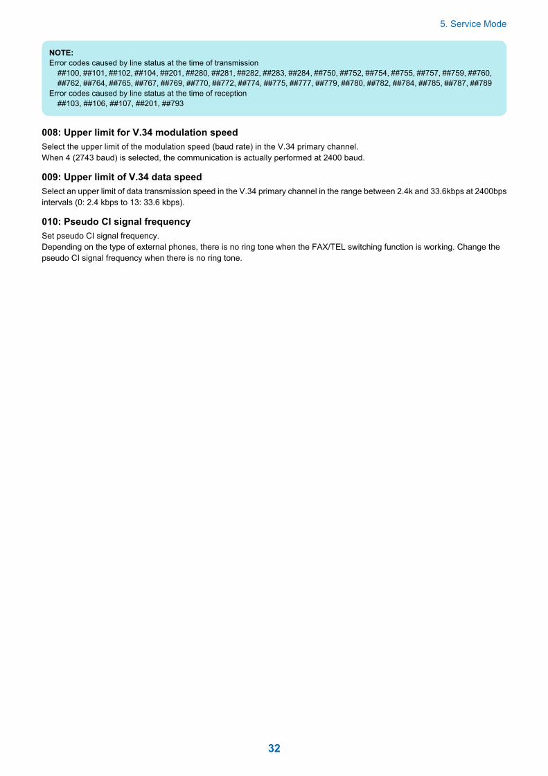
008: Upper limit for V.34 modulation speedSelect the upper limit of the modulation speed (baud rate) in the V.34 primary channel.When 4 (2743 baud) is selected, the communication is actually performed at 2400 baud.
009: Upper limit of V.34 data speedSelect an upper limit of data transmission speed in the V.34 primary channel in the range between 2.4k and 33.6kbps at 2400bpsintervals (0: 2.4 kbps to 13: 33.6 kbps).
010: Pseudo CI signal frequencySet pseudo CI signal frequency.Depending on the type of external phones, there is no ring tone when the FAX/TEL switching function is working. Change thepseudo CI signal frequency when there is no ring tone.
5. Service Mode
32

Setting of Numeric Parameter (NUMERIC Param.)
Configuration of Numeric Parameters
<1/10> <READY>
ReportSssw Menu Num Ncu Type IPFAX Print Clear Test
OK
001
002
003
004
005
006
007
008
xxxxx
xxxxx
xxxxx
xxxxx
xxxxx
xxxxx
xxxxx
xxxxx
← yyyyy {aaaaa bbbbb}
← yyyyy {aaaaa bbbbb}
← yyyyy {aaaaa bbbbb}
← yyyyy {aaaaa bbbbb}
← yyyyy {aaaaa bbbbb}
← yyyyy {aaaaa bbbbb}
← yyyyy {aaaaa bbbbb}
← yyyyy {aaaaa bbbbb}
No. Function Setting range Default value002 RTN transmission condition (1) 1 to 99% 10003 RTN transmission condition (2) 2 to 99 times 15004 RTN transmission condition (3) 1 to 99 lines 12005 NCC pause time (before ID
code)1 to 60 sec 4
006 NCC pause time (after ID code) 1 to 60 sec 4007 Prepose time at the time of mak-
ing a call0 to 9999 (x 10 ms) 0
009 Comparing the number of digitsbetween the sender's telephonenumber and the receiver's tele-phone number
0 to 20 digits 0
010 Line connection identificationtime
0 to 9999 (x 10 ms) 5500
011 T.30 T1 timer (for reception) 0 to 9999 (x 10 ms) 3500013 T.30 EOL timer 500 to 3000 (x 10 ms) 1300015 Hooking detection time 0 to 999 120016 Time until a temporary response
is obtained when switching FAX/TEL
0 to 9 4
017 Pseudo RBT signal pattern ONtime
0 to 999 100
018 Pseudo RBT signal pattern OFFtime (short)
0 to 999 0
019 Pseudo RBT signal pattern OFFtime (long)
0 to 999 200
020 Pseudo CI signal pattern ONtime
0 to 999 100
021 Pseudo CI signal pattern OFFtime (short)
0 to 999 0
022 Pseudo CI signal pattern OFFtime (long)
0 to 999 200
023 CNG detection level whenswitching FAX/TEL
0 to 7 4
024 Pseudo RBT transmission levelwhen switching FAX/TEL
10 to 20 (TYPE = STANDARD) 20
5. Service Mode
33

No. Function Setting range Default value025 CNG monitoring time when the
answering phone connectionfunction is set
026 Silent detection level when theanswering phone connectionfunction is set
027 V.21 low-speed flag preambledetection time
20 (-10 ms) 0
028 Off-hook PCB duty settings 1 to 99% 0 (50%)
002: RTN transmission condition (1)/003: RTN transmission condition (2)/004: RTN transmissioncondition (3)Set the RTN signal transmission condition.In the case of frequent errors caused by RTN signal transmission at the time of reception, increase the parameters to loosen theRTN signal transmission condition.
NOTE:Error codes caused by RTN signal transmission at the time of reception##104, ##107, ##114, ##201RTN signal transmission condition (1) is the ratio of error lines for the total number of lines per page of the received image.RTN signal transmission condition (2) is the reference value (*2) of burst error (*1).RTN signal transmission condition (3) is the number of errors that fail to meet the reference value of burst error.*1: Burst error (transmission errors with several continued lines)*2: Reference value (When "15" is set, transmission error with 15 consecutive lines is recognized as a burst error.)When any of the above conditions is detected during reception of image signals, RTN signal is sent after reception of the proceduresignal from the sending machine. Increasing such parameter sends less RTN signal.
005: NCC pause time (before ID code)Set the pause time to be automatically entered between the access code and ID code when dialing on NCC (New CommonCarrier) line.
006: NCC pause time (after ID code)Set the pause time to be automatically entered between the ID code and the other party's telephone number when dialing onNCC (New Common Carrier) line.
007: Prepose time at the time of making a callWhen automatically making a call, set the time from closing a line to making a call.
009: Comparing the number of digits between the sender's telephone number and the receiver'stelephone numberSet the TSI comparing the number of digits (last XX digits) when matching telephone numbers.
010: Line connection identification timeSet the line connection identification time.Increase this parameter in the case of frequent errors caused by line connection status at the time of communication.
NOTE:Error codes caused by line connection status##005, ##018The line connection identification time is the duration from when the dial signal is transmitted until the line is disconnected at thesending side, or from when DIS signal is transmitted until the line is disconnected at the reception side.
011: T.30 T1 timer (for reception)Set T1 timer at the time of reception (wait time until receiving the meaningful signal after DIS transmission).
013: T.30 EOL timerSet the receivable 1 line transmission time.In the case of a long line data length (e.g.: computer FAX), extend the transmission time to prevent reception errors.
5. Service Mode
34

015: Hooking detection timeSet the hooking detection time.
016: Time until the primary response is obtained when switching FAX/TELSet the time from when capturing the line until transmission of pseudo RBT at FAX/TEL switching function operation.
017: Pseudo RBT signal pattern ON time/ 018: Pseudo RBT signal pattern OFF time (short)/ 019: PseudoRBT signal pattern OFF time (long)Set the pattern of pseudo RBT signal to be sent at Fax/Tel switching function operation.
020: Pseudo CI signal pattern ON time/ 021: Pseudo CI signal pattern OFF time (short)/ 022: Pseudo CIsignal pattern OFF time (long)Set the pattern of pseudo CI signal to be sent at Fax/Tel switching function operation.
023: CNG detection level when switching FAX/TELSet the CNG detection level at Fax/Tel switching function operation.
024: Pseudo RBT transmission level when switching FAX/TELSet the transmission level of pseudo RBT at Fax/Tel switching function operation.
025: CNG monitoring time when the answering phone connection function is set
026: Silent detection level when the answering phone connection function is set
027: V21 low-speed flag preamble detection timeSet the period of time for judge detection of V.21 low-speed command preamble.Continuous detection for the fixed period of time leads to command analysis.
028: Off-hook PCB duty settingsSet the Off-hook PCB duty setting.When 0 or a value that is 100 or more is entered, the duty becomes 50%.
5. Service Mode
35

Setting of Destination (TYPE)
OverviewWhen the type shown on the display is set, all the service data is set to match each country domestic telecommunication standards.
5. Service Mode
36

Setting of Printer Functions (PRINTER)
Setting of Bit Switch (SSSW)
■ Functional ConfigurationBit Function 1 00 Not used - -1 Not used - -2 Not used - -3 Not used - -4 Not used - -5 Not used - -6 To hold the line (when an error
code occurs)Held Not held
7 Output a print log at the time ofthe DUMP report output
Output Not output
Details of Bit 6Select whether to hold the line when an error code occurs.However, in the case of vertical scanning prioritized recording, the priority order will be Letter -> A4 -> Legal even when 0 is setfor Bit 1 and Bit 0.
Details of Bit7Select whether to output a print log at the time of the DUMP report output.
■ Functional ConfigurationBit Function 1 00 Letter priority Set Not set1 Legal priority Set Not set2 Not used - -3 Not used - -4 Not used - -5 To prohibit reduced size printing
(A4)Prohibited Not prohibited
6 To prohibit reduced size printing(A4)
Prohibited Not prohibited
7 Vertical scanning prioritized re-cording
Set Not set
Details of Bit 0 and 1When an image which can be printed in 100% magnification and with the same number of divided pages on any of A4, letter andlegal is received, set which paper is prioritized for printing.With the settings of Bit 0 and Bit 1, the priority order of the recording paper is shown in the following table.
Bit 1 Bit 0 Priority order of the recording paper0 0 A4 -> Letter -> Legal0 1 Letter -> A4 -> Legal1 0 Legal -> Letter -> A41 1 Letter -> Legal -> A4
However, in the case of vertical scanning prioritized recording, the priority order will be Letter -> A4 -> Legal even when 0 is setfor Bit 1 and Bit 0.
5. Service Mode
37

Details of Bit 5 and 6Select whether to enable reduced size printing for A4 or LTR.
Details of Bit 7Set whether to set vertical scanning prioritized recording.
• "Set":In the event that an A4 long length image* is received while B4 recording paper and A4 recording paper are loaded, theimage is printed on B4 recording paper.
• "Not set":In the event that a B4 image is received while B5 recording paper with landscape orientation and A4 recording paper areloaded, the image is divided and printed on B5 recording paper with landscape orientation.
*: An image which is smaller than B4 in length and which cannot be printed at reduced size on A4 recording paper
■ SSSW-SW06
● Functional Construction
Bit Function 1 00 not used - -1 not used - -2 not used - -3 not used - -4 not used - -5 reduced printing from A4 to B5 enable disable6 not used - -7 not used - -
Detailed Discussions of Bit 5Set whether to execute the reduction print that forcibly reduces the A4 size document into the B5 size.This function is invalid when outputting the report.
Setting of Numeric Parameter (NUMERIC Param.)
<1/4><NUM> <READY>
ReportSssw Menu Num Ncu Type IP FAX Print Clear Test
OK
001
002
003
004
005
006
007
008
xxxxx
xxxxx
xxxxx
xxxxx
xxxxx
xxxxx
xxxxx
xxxxx
← yyyyy {aaaaa bbbbb}
← yyyyy {aaaaa bbbbb}
← yyyyy {aaaaa bbbbb}
← yyyyy {aaaaa bbbbb}
← yyyyy {aaaaa bbbbb}
← yyyyy {aaaaa bbbbb}
← yyyyy {aaaaa bbbbb}
← yyyyy {aaaaa bbbbb}
■ Numerical Parameter CompositionNo. Function Setting range Initial setting Unit01 Missing areas of printing
image when receiving im-age with longer lengththan standard
0 to 9999 12 1 mm
04 Leading edge blank area 0 to 9999 3 1 mm05 Trailing edge blank area 0 to 9999 3 1 mm
5. Service Mode
38

<001: printing upon reception of extra-length image>Use it to set the range of the image to be removed from when printing an extra-length received image.Lower the parameter to decrease the range if the trailing edge of the received image must be retained (as when it is longer thanthe effective recording length).
<004: leading edge margin>Use it to set the leading-edge margin for the effective recording length.
<005: trailing edge margin>Use it to set the trailing-edge margin for the effective recording length.
5. Service Mode
39
IPFAX Setting
IPFAX
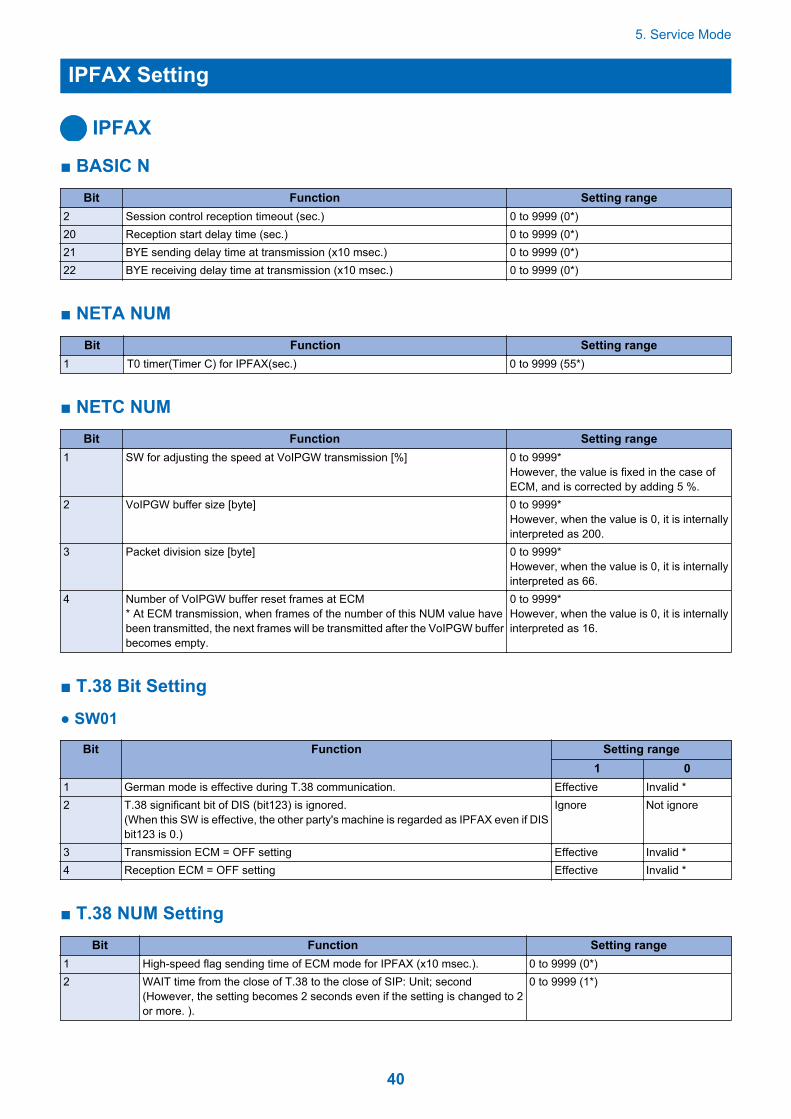
■ BASIC NBit Function Setting range
2 Session control reception timeout (sec.) 0 to 9999 (0*)20 Reception start delay time (sec.) 0 to 9999 (0*)21 BYE sending delay time at transmission (x10 msec.) 0 to 9999 (0*)22 BYE receiving delay time at transmission (x10 msec.) 0 to 9999 (0*)
■ NETA NUMBit Function Setting range
1 T0 timer(Timer C) for IPFAX(sec.) 0 to 9999 (55*)
■ NETC NUMBit Function Setting range
1 SW for adjusting the speed at VoIPGW transmission [%] 0 to 9999*However, the value is fixed in the case ofECM, and is corrected by adding 5 %.
2 VoIPGW buffer size [byte] 0 to 9999*However, when the value is 0, it is internallyinterpreted as 200.
3 Packet division size [byte] 0 to 9999*However, when the value is 0, it is internallyinterpreted as 66.
4 Number of VoIPGW buffer reset frames at ECM* At ECM transmission, when frames of the number of this NUM value havebeen transmitted, the next frames will be transmitted after the VoIPGW bufferbecomes empty.
0 to 9999*However, when the value is 0, it is internallyinterpreted as 16.
■ T.38 Bit Setting
● SW01
Bit Function Setting range1 0
1 German mode is effective during T.38 communication. Effective Invalid *2 T.38 significant bit of DIS (bit123) is ignored.
(When this SW is effective, the other party's machine is regarded as IPFAX even if DISbit123 is 0.)
Ignore Not ignore
3 Transmission ECM = OFF setting Effective Invalid *4 Reception ECM = OFF setting Effective Invalid *
■ T.38 NUM SettingBit Function Setting range
1 High-speed flag sending time of ECM mode for IPFAX (x10 msec.). 0 to 9999 (0*)2 WAIT time from the close of T.38 to the close of SIP: Unit; second
(However, the setting becomes 2 seconds even if the setting is changed to 2or more. ).
0 to 9999 (1*)
5. Service Mode
40

Initialization of Set Value (CLEAR)
OverviewSelecting the following items enables the applicable data to be initialized.When clear is executed, the setting items and numeric values for various parameters are set back to the factory setting values.
Item Data to be initializedTEL Registered telephone number data (*1)USSW SW Contents registered in the user data and service mode #1 to #3
Memory management contents of the user data are not cleared.Image data stored in the memory is not cleared.
SRV SW Contents of the user data and service mode #1 to #3, and #7NCU Contents of service mode #4SRV DATA Contents of the system dump listREPORT Contents of the communication management reportALL All Settings/Registration data (*1) except service mode #5 TYPE (*2)COUNTER The number of printed sheets, the number of read sheetsIP FAX Contents of IP Fax
*1: With models that can register information other than fax in destination, the telephone number data is not cleared even when"TEL" or "ALL" is executed.To clear the data, execute the following service mode of the host machine: COPIER> Function> CLEAR> ADRS-BK.*2: When "ALL" is executed, a value is registered in "TYPE" according to the location of the host machine (in the case of Japanesemodel, "STANDARD" is registered).
5. Service Mode
41

Test Mode (TEST)
Outline
■ Test Mode Construction
ReportSssw Menu Num Ncu Type IP FAX Print Clear Test
MODEM
FACULTY
DATA SET
ISDNMOD
ISDNMOD2
MODEM2
FACULTY2
Using Test Mode
1. Press the desired item to highlight; then, press the OK key to bring up its screen.The following table shows text mode items that are valid and invalid when a fax board is installed:Yes: may be used-: not used
Level 1 Level 2 Fax Board present
MODEM
RELAY-1 YesRELAY-2 -FREQ YesG3TX YesDTMFTX YesTONERX -V34G3TX Yes
FACULTY
G3 4800TX YesSPEAKER -DETECT1 -DETECT2 -DETECT3 -VOICETX -
DATA SET -ISDNMOD -ISDNMOD2 -
CAUTION:Do not use items in the table identified as "-."
5. Service Mode
42
MODEM Test
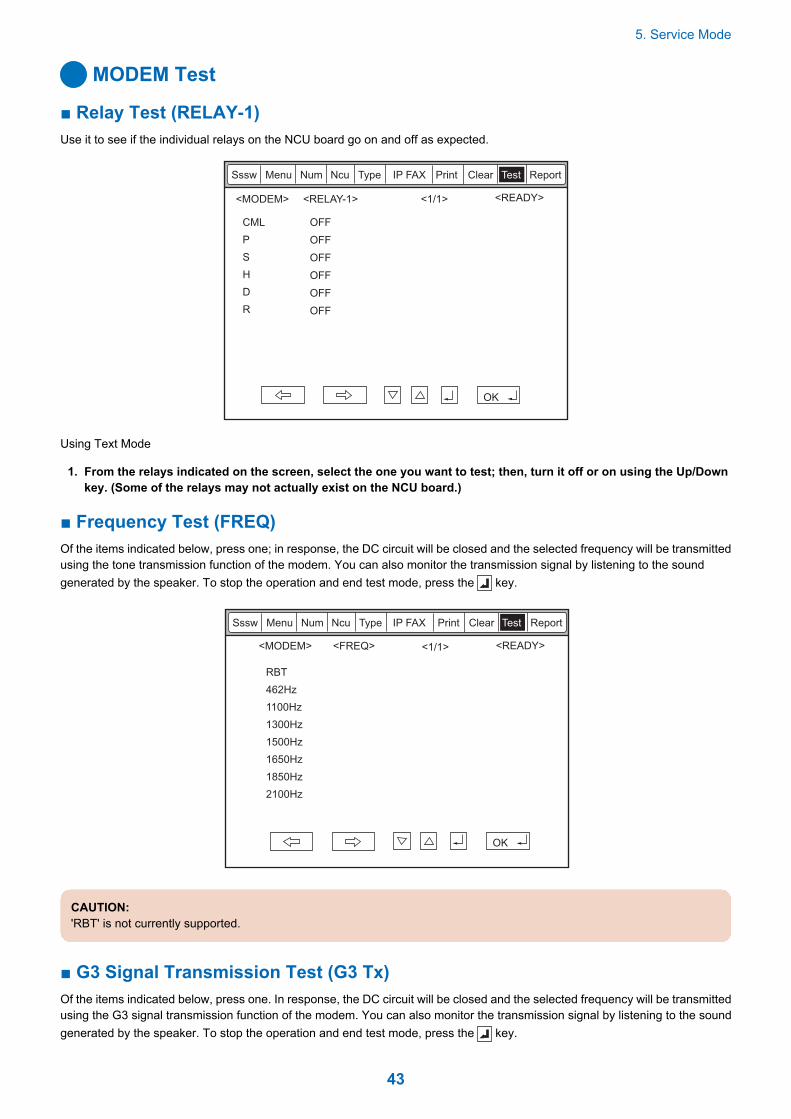
■ Relay Test (RELAY-1)Use it to see if the individual relays on the NCU board go on and off as expected.
<1/1><MODEM> <READY>
ReportSssw Menu Num Ncu Type IP FAX Print Clear Test
CML
P
S
H
D
R
<RELAY-1>
OFF
OFF
OFF
OFF
OFF
OFF
OK
Using Text Mode
1. From the relays indicated on the screen, select the one you want to test; then, turn it off or on using the Up/Downkey. (Some of the relays may not actually exist on the NCU board.)
■ Frequency Test (FREQ)Of the items indicated below, press one; in response, the DC circuit will be closed and the selected frequency will be transmittedusing the tone transmission function of the modem. You can also monitor the transmission signal by listening to the soundgenerated by the speaker. To stop the operation and end test mode, press the key.
<1/1> <READY>
ReportSssw Menu Num Ncu Type IP FAX Print Clear Test
<FREQ><MODEM>
OK
RBT
462Hz
1100Hz
1300Hz
1500Hz
1650Hz
1850Hz
2100Hz
CAUTION:'RBT' is not currently supported.
■ G3 Signal Transmission Test (G3 Tx)Of the items indicated below, press one. In response, the DC circuit will be closed and the selected frequency will be transmittedusing the G3 signal transmission function of the modem. You can also monitor the transmission signal by listening to the soundgenerated by the speaker. To stop the operation and end test mode, press the key.
5. Service Mode
43

<1/2> <READY>
ReportSssw Menu Num Ncu Type IP FAX Print Clear Test
<G3TX><MODEM>
OK
300bps
2400bps
4800bps
7200bps
9600bps
TC7200
TC9600
12000bps
<2/2> <READY>
ReportSssw Menu Num Ncu Type IP FAX Print Clear Test
<G3TX><MODEM>
OK
14400bps
300-ALL0
300-ALL1
300-1:1
300-1:4
300-4:1
CAUTION:'300-ALL0' through '300-4:1' are not currently supported.
■ DTMF Transmission TestOf the items indicated below, press one; in response, the DC circuit will be closed and the selected DTMF signal will be transmittedusing the DTMF transmission function of the modem. You can also monitor the transmission signal by listening to the speaker.To stop the operation and to end test mode, press the key.
<1/1> <READY>
ReportSssw Menu Num Ncu Type IP FAX Print Clear Test
<DTMFTX><MODEM>
OK
LONG 0 1 2 3 4 5 6 7 8 9 * #
Using Text Mode
5. Service Mode
44

1. From the items indicated on the screen, select the item you want to test; then, press the key on keypad thatcorresponds to the DTMF signal to test.
CAUTION:'SHORT' is not currently supported.
■ V.34 G3 Signal Transmission Test (V34G3Tx)Select the transmission speed you want to test, and then select a modulation speed (baud rate); in response, the V.34 G3transmission signal will be transmitted to the telephone line terminal and the speaker. To stop the operation and to end test mode,press the key.
<1/1> <READY>
ReportSssw Menu Num Ncu Type IP FAX Print Clear Test
<V34G3TX><MODEM>
OK
SPEED 33600bps
3429baud
3200baud
3000baud
2800baud
2743baud
2400baud
Using Text Mode
1. Select 'SPEED', and then select the speed you want to test using the Up/Down key.
2. Select the baud rate you want to test.
Function Test
■ 4800-bps Signal Transmission TestThe DC circuit will be closed, and a 4800-bps signal will be transmitted using the 4800-bps signal transmission function of themodem. You can also monitor the transmission signal by listening to the speaker. To stop the operation and end test mode, pressthe key.
<READY><1/1>
ReportSssw Menu Num Ncu Type IP FAX Print Clear Test
<FACULTY> <G34800TX>
OK
G34800TX
5. Service Mode
45

Service Report (REPORT)
System Data ListUse it to check the settings associated with the service soft switch and service parameters.
SERIAL NO XXXXXXXX
#1 SSSW
SW01 ----- 00000000
SW02 ----- 10000000
SW03 ----- 00000000
SW04 ----- 10000000
SW05 ----- 00000000
SW06 ----- 10000000
SW07 ----- 00000000
SW08 ----- 00000000
SW09 ----- 00000000
SW10 ----- 00000000
SW11 ----- 00000000
SW12 ----- 00000011
SW13 ----- 00000000
SW14 ----- 00000000
SW15 ----- 00000000
SW16 ----- 00000000
SW17 ----- 00000000
SW18 ----- 00000000
SW19 ----- 00011000
SW20 ----- 00000000
SW21 ----- 00000000
SW22 ----- 00000000
SW23 ----- 00000000
SW24 ----- 00000000
SW25 ----- 00000000
SW26 ----- 00100000
SW27 ----- 00000000
SW28 ----- 00000000
SW29 ----- 00000000
SW30 ----- 00000000
SW31 ----- 00000000
SW32 ----- 00000000
SW33 ----- 00000000
SW34 ----- 00000000
SW35 ----- 00000000
SW36 ----- 00000000
SW37 ----- 00000000
SW38 ----- 00000000
SW39 ----- 00000000
SW40 ----- 00000000
SW41 ----- 00000000
SW42 ----- 00000000
SW43 ----- 00000000
SW44 ----- 00000000
SW45 ----- 00000000
SW46 ----- 00000000
SW47 ----- 00000000
SW48 ----- 00000000
SW49 ----- 00000000
SW50 ----- 00000000
#2 MENU
01: ----- 0
02: ----- 0
03: ----- 0
04: ----- 0
05: ----- 0
06: ----- 0
07: ----- 10
08: ----- 0
09: ----- 0
10: ----- 2
******************************
*** SYSTEM DATA LIST ***
******************************
2003 09/02 TUE 12:00 FAX 001
System Dump List
NOTE:A system dump list is generated when you execute the following in service mode: FAX > Report > DUMP.
Use it to check the history of communications, both successful and error.
5. Service Mode
46

SERIAL NO XXXXXXXX
CLEAR DATE 2013 02/03 FRI 13:37
TX = 1298
A4 = 1302 B4 = 49 A3 = 27 LTR = 0 LGL = 0
RX = 1572
A4 = 1581 B4 = 59 A3 = 59 LTR = 0 LGL = 0
NWSPD = 0
33600 = 1 31200 = 0 28800 = 2986 26400 = 0 24000 = 0
21600 = 0 19200 = 0 16800 = 0 14400 = 0 12000 = 0
9600 = 0 7200 = 0 4800 = 0 2400 = 0
14400 = 83 12000 = 1 TC9600 = 0 TC7200 = 0
14400 = 0 14400 = 0
9600 = 2 7200 = 0 4800 = 4 2400 = 0
STD = 60 FINE = 2839 SUPER = 107 ULTRA = 71
MH = 7 MR = 32 MMR = 9 JBIG = 3029 JPEG = 0
G3 = 37 ECM = 3040 G4 = 0 IPECM = 0 IPG3 = 0
*******************************
*** SYSTEM DUMP LIST ***
*******************************
2013 04/05 FRI 12:00 FAX 001
#000 0 0 0 0 0 0 0 0
0 0 0 0 0 0 0 0
0 0 2 0 0 0 0 0
0 0 0 0 0 0 0 0
0 0 0 0 0 0 0 0
0 0 0 0 0 0 0 0
0 0 0 0 0 0 0 0
0 0 0 0 0 0 0 0
0 0 0 0 0 0 0 0
0 0 0 0 0 0 0 0
0 0 0 0 0 0 0 0
0 0 0 22 0 0 0 0
0 0 0 0 0 0 0 0
#100 0 0 0 0 0 0 18 0
*1*2*1*2*3
*4*5*6
*7
*3
*1: RX, total reception number of times; TX, total transmission number of times.*2: number of pages sent/received according to original size.*3: number of pages sent/received in connection with different modem speeds (NWSPD : For IPFAX communication count).*4: number of communication pages by resolution(Standard, Fine, Super Fine, Ultra Fine).*5: number of pages sent/received in connection with different coding methods.*6: number of transmissions/receptions according to mode.*7: number of occurrences according to error code.Indication sample
#280 1 7 3 0 0
↑ ↑ ↑
number of errors ##280 number of errors ##281 number of errors ##282
It provides error information on the 3 most recent communications.
5. Service Mode
47
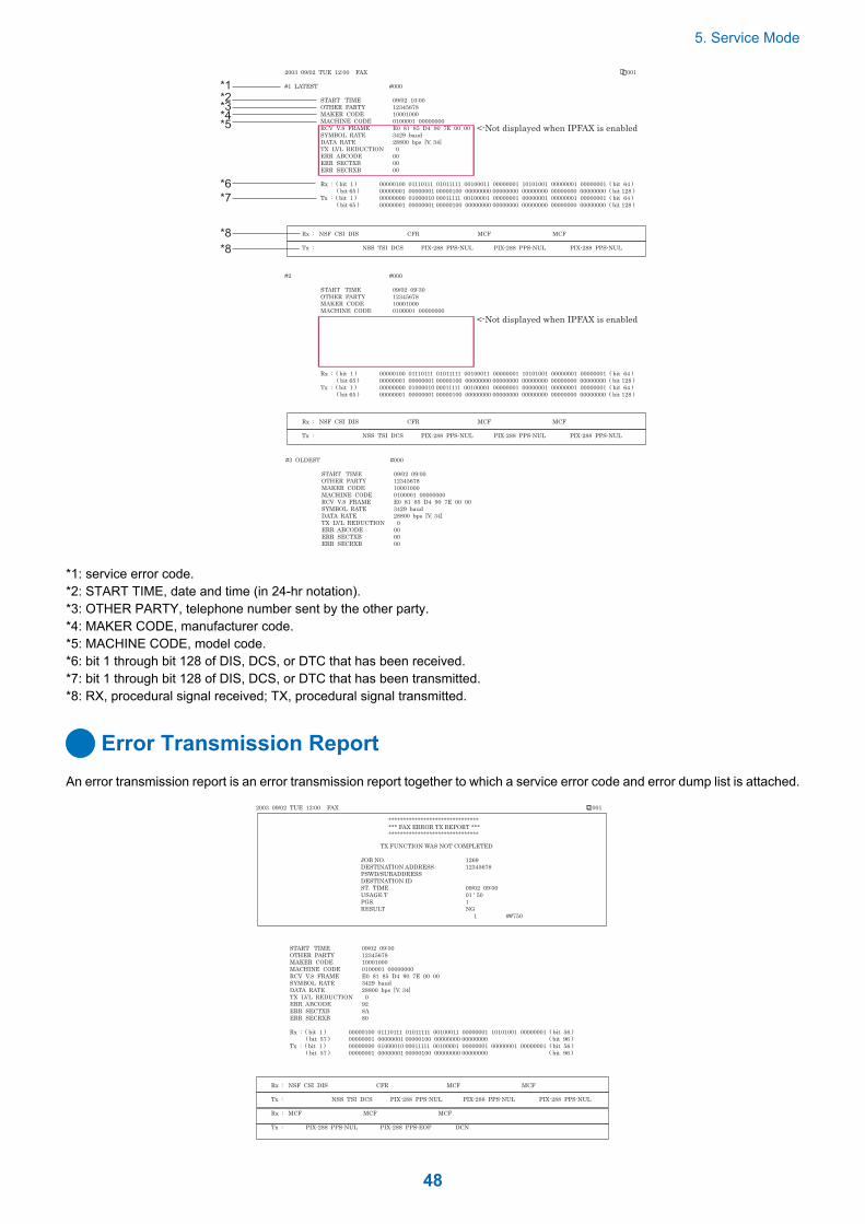
*1*2
*8
*3*4*5
*6
*7
2003 09/02 TUE 12:00 FAX
#1 LATEST #000
START TIME 09/02 10:00 OTHER PARTY 12345678 MAKER CODE 10001000 MACHINE CODE 0100001 00000000 RCV V.8 FRAME E0 81 85 D4 90 7E 00 00 SYMBOL RATE 3429 baud DATA RATE 28800 bps [V. 34] TX LVL REDUCTION 0 ERR ABCODE 00 ERR SECTXB 00 ERR SECRXB 00
Rx : ( bit 1 ) 00000100 01110111 01011111 00100011 00000001 10101001 00000001 00000001 ( bit 64 ) ( bit 65 ) 00000001 00000001 00000100 00000000 00000000 00000000 00000000 00000000 ( bit 128 ) Tx : ( bit 1 ) 00000000 01000010 00011111 00100001 00000001 00000001 00000001 00000001 ( bit 64 ) ( bit 65 ) 00000001 00000001 00000100 00000000 00000000 00000000 00000000 00000000 ( bit 128 )
001
Rx : NSF CSI DIS CFR MCF MCF
Tx : NSS TSI DCS PIX-288 PPS-NUL PIX-288 PPS-NUL PIX-288 PPS-NUL
#2 #000
START TIME 09/02 09:30 OTHER PARTY 12345678 MAKER CODE 10001000 MACHINE CODE 0100001 00000000
Rx : ( bit 1 ) 00000100 01110111 01011111 00100011 00000001 10101001 00000001 00000001 ( bit 64 ) ( bit 65 ) 00000001 00000001 00000100 00000000 00000000 00000000 00000000 00000000 ( bit 128 ) Tx : ( bit 1 ) 00000000 01000010 00011111 00100001 00000001 00000001 00000001 00000001 ( bit 64 ) ( bit 65 ) 00000001 00000001 00000100 00000000 00000000 00000000 00000000 00000000 ( bit 128 )
Rx : NSF CSI DIS CFR MCF MCF
Tx : NSS TSI DCS PIX-288 PPS-NUL PIX-288 PPS-NUL PIX-288 PPS-NUL
#3 OLDEST #000
START TIME 09/02 09:00 OTHER PARTY 12345678 MAKER CODE 10001000 MACHINE CODE 0100001 00000000 RCV V.8 FRAME E0 81 85 D4 90 7E 00 00 SYMBOL RATE 3429 baud DATA RATE 28800 bps [V. 34] TX LVL REDUCTION 0 ERR ABCODE 00 ERR SECTXB 00 ERR SECRXB 00
*8
<-Not displayed when IPFAX is enabled
<-Not displayed when IPFAX is enabled
*1: service error code.*2: START TIME, date and time (in 24-hr notation).*3: OTHER PARTY, telephone number sent by the other party.*4: MAKER CODE, manufacturer code.*5: MACHINE CODE, model code.*6: bit 1 through bit 128 of DIS, DCS, or DTC that has been received.*7: bit 1 through bit 128 of DIS, DCS, or DTC that has been transmitted.*8: RX, procedural signal received; TX, procedural signal transmitted.
Error Transmission ReportAn error transmission report is an error transmission report together to which a service error code and error dump list is attached.
TX FUNCTION WAS NOT COMPLETED
JOB NO. 1269DESTINATION ADDRESS 12345678PSWD/SUBADDRESSDESTINATION IDST. TIME 09/02 09:00USAGE T 01 ' 50PGS. 1RESULT NG 1 ##750
********************************** FAX ERROR TX REPORT **********************************
2003 09/02 TUE 12:00 FAX 001
START TIME 09/02 09:00 OTHER PARTY 12345678 MAKER CODE 10001000 MACHINE CODE 0100001 00000000 RCV V.8 FRAME E0 81 85 D4 90 7E 00 00 SYMBOL RATE 3429 baud DATA RATE 28800 bps [V. 34] TX LVL REDUCTION 0 ERR ABCODE 92 ERR SECTXB 8A ERR SECRXB 80
Rx : ( bit 1 ) 00000100 01110111 01011111 00100011 00000001 10101001 00000001 ( bit 56 ) ( bit 57 ) 00000001 00000001 00000100 00000000 00000000 ( bit 96 ) Tx : ( bit 1 ) 00000000 01000010 00011111 00100001 00000001 00000001 00000001 ( bit 56 ) ( bit 57 ) 00000001 00000001 00000100 00000000 00000000 ( bit 96 )
Rx : NSF CSI DIS CFR MCF MCF
Tx : NSS TSI DCS PIX-288 PPS-NUL PIX-288 PPS-NUL PIX-288 PPS-NUL
Rx : MCF MCF MCF
Tx : PIX-288 PPS-NUL PIX-288 PPS-EOP DCN
5. Service Mode
48

Installation(SuperG3 FAX Board-AU1)
6How to Check the Installation
Procedure........................................50Pre-checks.......................................... 51Installation Procedure......................... 52Operation Setting................................ 60

How to Check the Installation Procedure
SymbolsThe frequently-performed operations are described with symbols in this procedure.
1x 1x 1x
Install
Screw
Packaged Item Remove Tighten Loosen
1x
Connect
Connector
DisconnectInstall
Harness (Common for Guides and Clamps)
Remove
1x 1x
Connect
Power Cord
Disconnect
Check visuallyCheck the sound CheckOFF CleaningON Push
Power
Unused Parts
1x 1x
6. Installation(Super G3 FAX Board-AU1)
50

Pre-checks
Points to Note at Installation• When installing the Super G3 2nd Line Fax Board and
this equipment at the same time, check the partsincluded in the package, and install them following theInstallation Procedure for Super G3 2nd Line Fax Board.
CAUTION:Marked portionWhen tightening the screws, do not tighten them tootightly. Otherwise, there is a risk of damage anddeformation of screw holes.
Check Item When Turning OFFthe Main PowerCheck that the main power is OFF.
1. Turn OFF the main power switch.
2. Check that the display in the Control Panel and thelamp of the main power are turned off, and thendisconnect the power plug.
Installation Outline Drawing
Checking the Contents
1x
1x
1x
M3x6
2x
1x
or
<For Europe>
FAX Approval Label
6 Contact type
Only for Europe
1x
1x
1x
1x
1x
<For USA and Taiwan>
<Others>Including guides
6. Installation(Super G3 FAX Board-AU1)
51

Installation Procedure
Remove the Covers
1
2x
2
1x
Removing the ReaderConnecting Plate
1
2x
1x
2
6. Installation(Super G3 FAX Board-AU1)
52

3
1x
4
5x
1x
NOTE:The removed 1 screw will be used in step 3 of "Installingthe Fax Unit".
5
Installing the Fax Unit
NOTE:When installing the Super G3 2nd Line Fax Board at thesame time, do not perform the following procedure, butstart from "Installation Procedure > Installing the Fax Unit"of Super G3 2nd Line Fax Board Installation Procedure.
6. Installation(Super G3 FAX Board-AU1)
53

1
NOTE:Remove the packing tape and other materials and Installthe Fax Unit.
CAUTION:• When installing the FAX Unit, be careful not to trap
the 2 Cables of the FAX Unit.• Do not directly touch the speaker [A] of the FAX
Unit.• Be sure not to damage the speaker [A].
[A]
2x
M3x6
2
3
NOTE:Use the screws removed in step 4 of "Removing theReader Connecting Plate".
1x
4
2x
1x
6. Installation(Super G3 FAX Board-AU1)
54

5
1x
6
7
1x
8
9
8x
Installing the Covers
1
1x
6. Installation(Super G3 FAX Board-AU1)
55

2
NOTE:Store the removed Face Cover in the Tray Guide in step5.
3
2x
4
6. Installation(Super G3 FAX Board-AU1)
56

5
NOTE:• Store the Face Cover removed in step 2 in the Tray
Guide.• The storage locations differ depending on the number
of Face Covers ("Less than 4 Face Covers" or "4Face Covers").
• Be sure to store the removed Face Covers as shownbelow.
In the case of four
In the case of less than four
6
Procedure after Work
1
6. Installation(Super G3 FAX Board-AU1)
57
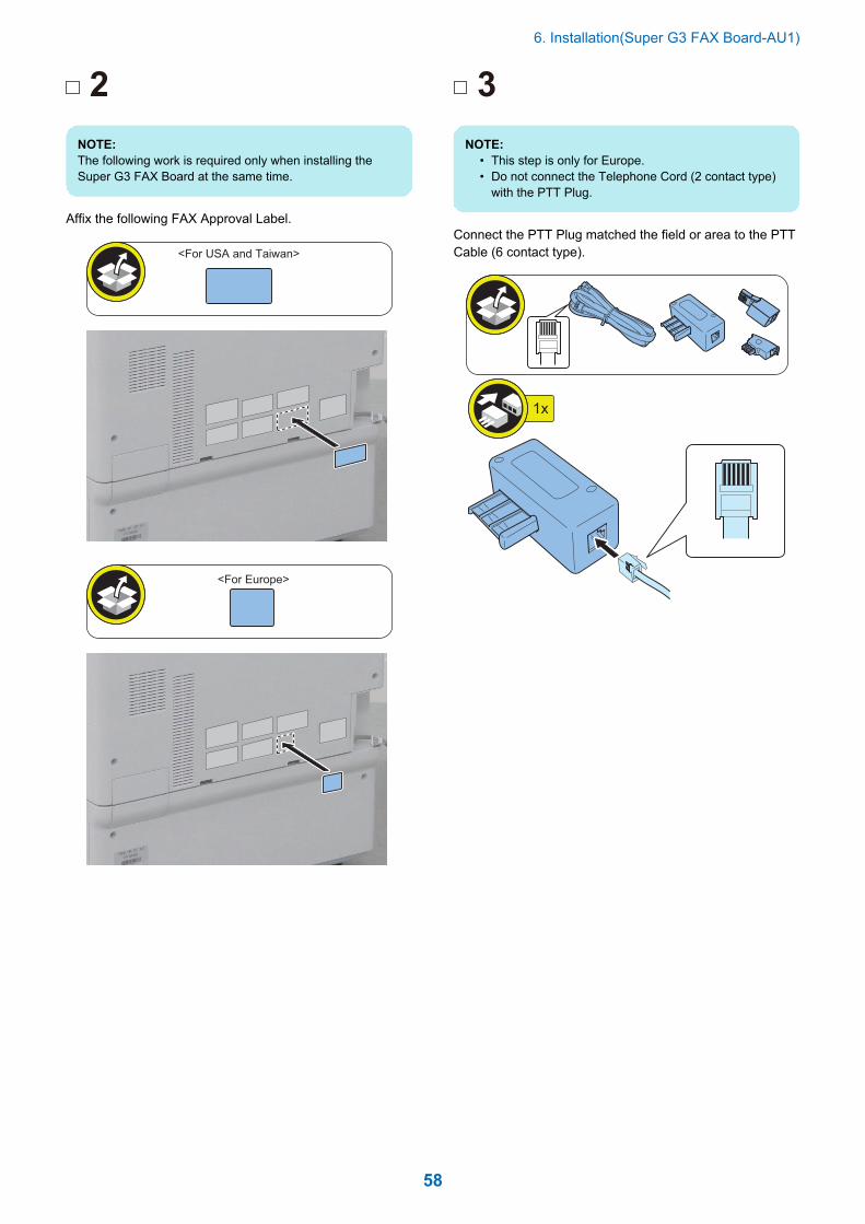
2
NOTE:The following work is required only when installing theSuper G3 FAX Board at the same time.
Affix the following FAX Approval Label.
<For USA and Taiwan>
<For Europe>
3
NOTE:• This step is only for Europe.• Do not connect the Telephone Cord (2 contact type)
with the PTT Plug.
Connect the PTT Plug matched the field or area to the PTTCable (6 contact type).
1x
6. Installation(Super G3 FAX Board-AU1)
58
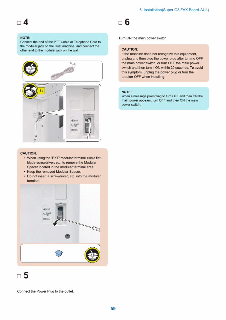
4
NOTE:Connect the end of the PTT Cable or Telephone Cord tothe modular jack on the Host machine, and connect theother end to the modular jack on the wall.
1x
CAUTION:• When using the "EXT" modular terminal, use a flat-
blade screwdriver, etc. to remove the ModularSpacer located in the modular terminal area.
• Keep the removed Modular Spacer.• Do not insert a screwdriver, etc. into the modular
terminal.
5
Connect the Power Plug to the outlet.
6
Turn ON the main power switch.
CAUTION:If the machine does not recognize this equipment,unplug and then plug the power plug after turning OFFthe main power switch, or turn OFF the main powerswitch and then turn it ON within 20 seconds. To avoidthis symptom, unplug the power plug or turn thebreaker OFF when installing.
NOTE:When a message prompting to turn OFF and then ON themain power appears, turn OFF and then ON the mainpower switch.
6. Installation(Super G3 FAX Board-AU1)
59

Operation Setting
Type SettingsSelect the country/region of the FAX Board in Service Mode(Level 1): FAX > Type > TYPEThis setting performs the parameter settings to match thecommunication specification of the country/region.
1. Set the TYPE of country/region to install thismachine, and then press OK.
• Service Mode (Level 1) > FAX > Type > TYPE
2. Confirm that service mode (level 1) parameter belowis "0". In the case, parameter is "1", change to "0".
• COPIER > OPTION > DSPLY-SW > SDTM-DSP
NOTE:Change the parameter to "0" to hide [Settings/Registration] > [Preferences] > [Timer/Energy Settings] >[Auto Shutdown Time] and disable the auto shut down.
3. Turn OFF/ON the main power switch to enable thissetting.
Basic Setting
NOTE:When "System Manager Information Settings" is set, besure to follow the direction of user administrator in orderto log in as an administrator.
In this section, make only minimum settings required for FAXcommunication.
1. Set the user telephone number.[Settings/Registration] > [Function Settings] > [Send] >[Fax Settings] > [Set Line] > [Line 1] > [Register UserTelephone No] > Enter the fax number > [OK]
2. Set Type of telephone line.[Settings/Registration] > [Function Settings] > [Send] >[Fax Settings] > [Set Line] > [Line 1] > [Select Line Type]> Select the line type to connect > [OK]
3. Turn OFF/ON the main power switch after setting theuser telephone numbers and the type of telephoneline.
Fax communication testPerform the communication test to check if FAX functionworks Correctly.
1. Switch the control panel display to [Fax] display.
2. Send the test document from this machine toanother machine that can handle thecommunication test to check that this machine cansend the data correctly.
3. Send the test document from the target to thismachine to check if the machine can receive thedocument properly.
6. Installation(Super G3 FAX Board-AU1)
60

Installation(SuperG3 2nd Line FaxBoard-AU1)
7How to Check the Installation
Procedure........................................62Pre-checks.......................................... 63Installation Procedure......................... 64Checking the Operation...................... 76

How to Check the Installation Procedure
SymbolsThe frequently-performed operations are described with symbols in this procedure.
1x 1x 1x
Install
Screw
Packaged Item Remove Tighten Loosen
1x
Connect
Connector
DisconnectInstall
Harness (Common for Guides and Clamps)
Remove
1x 1x
Connect
Power Cord
Disconnect
Check visuallyCheck the sound CheckOFF CleaningON Push
Power
Unused Parts
1x 1x
7. Installation(Super G3 2nd Line Fax Board-AU1)
62

Pre-checks
Points to Note at Installation• When installing the Super G3 FAX Board and this
equipment at the same time, be sure to install them byreferring to this document after checking "Checking theContents" of Super G3 FAX Board.
CAUTION:Marked portionWhen tightening the screws, do not tighten them tootightly. Otherwise, there is a risk of damage anddeformation of screw holes.
Check Item When Turning OFFthe Main PowerCheck that the main power is OFF.
1. Turn OFF the main power switch.
2. Check that the display in the Control Panel and thelamp of the main power are turned off, and thendisconnect the power plug.
Installation Outline Drawing
Checking the Contents
1x 1x
1x
1x
1x
1x 1x
M3x6
7x 1x
<Included in Taiwan>
FAX Approval Label
6 Contact type
Only for Europe
1x
1x
1x
1x
1x
7. Installation(Super G3 2nd Line Fax Board-AU1)
63

Installation Procedure
Remove the Covers
NOTE:When a Telephone Cord is connected, disconnect it.
1
2x
2
1x
Removing the Fax Unit (Whenthe Fax Unit is installed)
NOTE:When the Fax Unit is not installed, proceed to "InstallationProcedure > Installing the Fax Unit".
1
2x
1x
2
7. Installation(Super G3 2nd Line Fax Board-AU1)
64
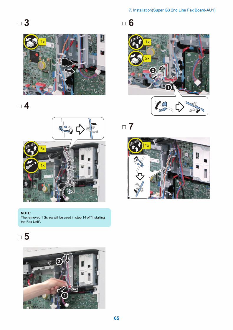
3
1x
4
1x
5x
NOTE:The removed 1 Screw will be used in step 14 of "Installingthe Fax Unit".
5
6
1x
2x
7
1x
7. Installation(Super G3 2nd Line Fax Board-AU1)
65
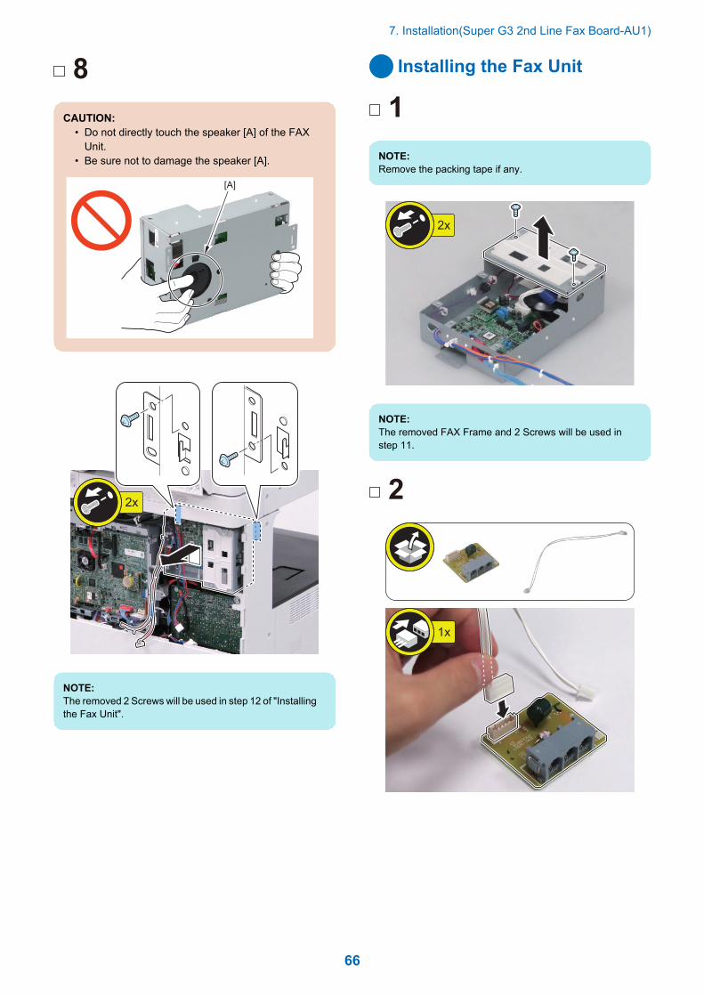
8
CAUTION:• Do not directly touch the speaker [A] of the FAX
Unit.• Be sure not to damage the speaker [A].
[A]
2x
NOTE:The removed 2 Screws will be used in step 12 of "Installingthe Fax Unit".
Installing the Fax Unit
1
NOTE:Remove the packing tape if any.
2x
NOTE:The removed FAX Frame and 2 Screws will be used instep 11.
2
1x
7. Installation(Super G3 2nd Line Fax Board-AU1)
66

3
2x
M3x6
4
5
3x
6
1x
7. Installation(Super G3 2nd Line Fax Board-AU1)
67

7
8
5x
M3x6
9
NOTE:Secure the included in [A] Cable in place using the WireSaddle.
3x [A]
[A]
1x
10
1x
7. Installation(Super G3 2nd Line Fax Board-AU1)
68

11
CAUTION:Installing the PlateBe sure to install the FAX Frame in an orientationappropriate for the country or region where themachine is installed.
<EU> <Excluding EU>
NOTE:Use the screws and the FAX Frame removed in step 1.
2x
12
NOTE:• Use the screws removed in step 8 of "Removing the
Fax Unit (When the Fax Unit is installed)".• When installing the Super G3 Fax Board at the same
time, be sure to use the screws included with theSuper G3 Fax Board.
CAUTION:• When installing the FAX Unit, be careful not to trap
the 2 Cables of the FAX Unit.• Do not directly touch the speaker [A] of the FAX
Unit.• Be sure not to damage the speaker [A].
[A]
2x
7. Installation(Super G3 2nd Line Fax Board-AU1)
69

13
14
NOTE:Use the screws removed in step 4 of "Removing the FaxUnit (When the Fax Unit is installed)".
1x
15
3x
1x
16
1x
17
18
1x
7. Installation(Super G3 2nd Line Fax Board-AU1)
70

19
NOTE:Open the Wire Saddle if it is closed.
20
8x
Installing the Covers
1
1x
2
NOTE:• When installing the Super G3 FAX Board (1-Line) at
the same time, remove the Face Cover of the 1-Line.• Store the removed Face Cover in the Tray Guide in
step 5.
7. Installation(Super G3 2nd Line Fax Board-AU1)
71

3
2x
4
5
NOTE:• Store the Face Cover removed in step 2 in the Tray
Guide.• The storage locations differ depending on the number
of Face Covers ("Less than 4 Face Covers" or "4Face Covers").
• Be sure to store the removed Face Covers as shownbelow.
In the case of four
In the case of less than four
6
7. Installation(Super G3 2nd Line Fax Board-AU1)
72

Procedure after Work
1
NOTE:When installing the Super G3 FAX Board at the same time,be sure to affix an appropriate Modular Label included inthe package of the Super G3 FAX Board.
2
NOTE:The following work is required only when installing theSuper G3 FAX Board at the same time.
Affix the following FAX Approval Label.
<For USA and Taiwan>
<For Europe>
7. Installation(Super G3 2nd Line Fax Board-AU1)
73

3
NOTE:This step is only for Taiwan.
Affix the following FAX Approval Label.
4
NOTE:• This step is only for Europe.• When installing the Super G3 FAX Board at the same
time, assemble it by following the same procedure.
Connect the PTT Plug matched the field or area to the PTTCable (6 contact type).
CAUTION:Do not connect the Telephone Cord (2 contact type)with the PTT Plug.
1x
7. Installation(Super G3 2nd Line Fax Board-AU1)
74

5
CAUTION:• When using the "EXT" modular terminal, use a flat-
blade screwdriver, etc. to remove the ModularSpacer located in the modular terminal area.
• Keep the removed Modular Spacer.• Do not insert a screwdriver, etc. into the modular
terminal.
NOTE:Connect the end of the PTT Cable or Telephone Cord tothe Modular Jack (LINE 1 and LINE 2) on the hostmachine, and connect the other end to the Modular Jackon the wall.
2x
6Connect the power plug to the outlet.
7Turn ON the main power switch.
CAUTION:If the machine does not recognize this equipment,unplug and then plug the power plug after turning OFFthe main power switch, or turn OFF the main powerswitch and then turn it ON within 20 seconds. To avoidthis symptom, unplug the power plug or turn thebreaker OFF when installing.
NOTE:When a message prompting to turn OFF and then ON themain power appears, turn OFF and then ON the mainpower switch.
8If a message prompting the user to update the versionappears, press [Update] to automatically update the versionof this equipment.
NOTE:If [Skip] is selected, a message prompting the user toupdate the version will appear every time the host machineis started.In the service mode (Level 2) shown below, it is possibleto set not to display the message.
• COPIER > OPTION > FNC-SW > VER-CHNG
7. Installation(Super G3 2nd Line Fax Board-AU1)
75

Checking the Operation
NOTE:After completion of "Checking the Operation" of the SuperG3 FAX Board, execute "Checking the Operation" of thisequipment.
Type SettingsSelect the country/region of the FAX Board in Service Mode(Level 1): FAX > Type > TYPEThis setting performs the parameter settings to match thecommunication specification of the country/region.
1. Set the TYPE of country/region to install thismachine, and then press OK.
• Service Mode (Level 1) > FAX > Type > TYPE
2. Confirm that service mode (level 1) parameter belowis "0". In the case, parameter is "1", change to "0".
• COPIER > OPTION > DSPLY-SW > SDTM-DSP
NOTE:Change the parameter to "0" to hide [Settings/Registration] > [Preferences] > [Timer/Energy Settings] >[Auto Shutdown Time] and disable the auto shut down.
3. Turn OFF/ON the main power switch to enable thissetting.
Basic Settings
NOTE:When "System Manager Information Settings" is set, besure to follow the direction of user administrator in orderto log in as an administrator.
In this section, make only minimum settings required for FAXcommunication.
1. Set the user telephone number.[Settings/Registration] > [Function Settings] > [Send] >[Fax Settings] > [Set Line] > [Line 2] > [Register UserTelephone No.] > Enter FAX number > [OK]
2. Set the type of telephone line.[Settings/Registration] > [Function Settings] > [Send] >[Fax Settings] > [Set Line] > [Line 2] > [Select Line Type]> Select the line type to connect > [OK]
3. Turn OFF/ON the main power switch after setting theuser telephone numbers and the type of telephoneline.
FAX Communication TestPerform communication test to check if FAX function workscorrectly.
1. Switch the control panel display to [Fax] display.
2. Select the sending line.Press [Fax] > [Options] > [Select Line], select the addedline, then press [OK] button.
3. Send and receive a test original between theequipment and a remote unit with which acommunication test can be performed and check ifit can be sent and receive correctly.
1. Press [Status Monitor/Cancel] > [Send] > [Job Log]and select [Fax] from pull down menu.
2. Press [Comm Report] > [OutPut Normally] > [StartPrinting].
3. The number printed following colon (:) in"COMM.MODE" field on COMMUNICATIONMANAGEMENT REPORT TX/RX shows line typeused for sending/receiving.E.g. "ECM:2" => Line 2
NOTE:If E744-5000 error code (Fax software version mismatcherror) occurred while sending or receiving fax, upgrade thefirmware of 2-line Fax to the latest version.
7. Installation(Super G3 2nd Line Fax Board-AU1)
76