service manual -...
TRANSCRIPT

Be Strong.™
P/N: 001-7129 Rev D (5/21/2007)
Service ManualTreadClimber®, Model TC916 Commercial Series

�
Attention!
this mAnuAl is intended for Authorized nAutilus or nAutilus certified service personnel And not for the consumer. there Are no user serviceAble pArts. servicing of the nAutilus commerciAl series treAdmill by other thAn Authorized nAutilus or nAutilus certified service personnel mAy result in voiding of the wArrAnty.
for detAiled instructions And informAtion on Assembly And use for the nAutilus® commericAl series treAdclimber®, model tc916, refer to the Assembly And owner’s mAnuAls.
SecuRe loNg haiR aND looSe clothiNg befoRe woRkiNg NeaR the tReaDcliMbeR® walkiNg SuRface oR tReaDleS.

�Nautilus® TreadClimber®, Model TC916 Service Manual
Important Safety precautIonS............. 4
proDuct SpecIfIcatIonS ........................... 6
mechanIcal ServIce
1.0 Removing The Console ............................................. 72.0 Accessing The Console For Programming ................ 83.0 Removing Rear Step ................................................. 94.0 VSD Assembly Grounding ....................................... 105.0 Removing Uprights ................................................. 126.0 Removing Base Plastic ........................................... 147.0 Belt Tension and Alignment ................................... 158.0 Belt and Deck Replacement ................................... 169.0 Treadle Adjustment Troubleshooting ..................... 1810.0 Replacement of Pivot Covers ............................... 2411.0 Replacement of Hydraulic Cylinders .................... 26 12.0 Vibration Troubleshooting .................................... 28
carDIo conSole coDeS ........................... 30
partS lISt
Ordering Replacement Parts ............................................... 33
eXploDeD vIeWS
Working with exploded views ...................................... 37Base Frame with Drive Motor ...................................... 37Base Frame with VSD Motor Control Board ................ 37Base Frame with Dependency Link and Hydraulic System ..................................................... 38Dependency Link .......................................................... 38Treadle Assembly ......................................................... 39Console Upright Assembly, Rear Step and Console Assembly ................................................... 39Base Frame Covers (Right side.) ................................... 40Base Frame Covers (Left side.) ..................................... 40Treadle Deck and Belt Assembly (Right side.) ............. 41Treadle Deck and Belt Assembly (Left side.) ................ 41Treadle Arm Assembly (Right side.) ............................. 42Treadle Arm Assembly (Left side.) ............................... 42Treadle Covers - Top and Bottom (Right side.) ............. 43Treadle Covers - Top and Bottom (Left side.) ............... 43ROC Bar Assembly ........................................................ 44Console Upright and Cover Assembly .......................... 44Rear Step and Support Platform .................................. 45
electronIc trouBleShootInG
Summary .................................................... 46
WIrInG SchematIcS .................................. 51
Important contact numBerS ............ 58
table of coNteNtS

�
iMPoRtaNt Safety PRecautioNS - Save theSe iNStRuctioNS
Important Safety InStructIonS The following definition applies to the word “Warning” found throughout this manual:
WarnInG - Used to call attention to POTENTIAL hazards that could result in personal injury or loss of life.
When uSInG electrIcal eQuIpment alWayS folloW theSe BaSIc precautIonS:
reaD all InStructIonS Before uSInG the machIne.
Read this manual in full before operating the TreadClimber® machine. Failure to follow these guidelines can produce a serious or possible fatal electrical shock hazard or other serious injury. Consult a qualified electrician as required.
1. The controller Stop Key does not turn off the electrical current to the TreadClimber® exercise machine. The TreadClimber® machine continues to draw power, even when the controller is off. To avoid electric shock, do not remove TreadClimber® hood or place hands beneath the TreadClimber® exercise machine while the machine is plugged into a power source.
2. Do not start the TreadClimber® machine when someone else is standing on the walk belts.
3. Keep walk speed and treadle displacement at the lowest settings when getting on and off the TreadClimber®
machine.
4. Keep the area underneath and around the TreadClimber® exercise machine clear.
5. Never position the TreadClimber® exercise machine with the back end (direction of belt travel) facing a wall or any other objects such as furniture or other pieces of fitness equipment. Failure to keep the rear space of the machine clear can prevent safe exit of the TreadClimber® machine in an emergency situation such as falling. Allow a minimum of four feet behind the TreadClimber® exercise machine.
6. Before each use of this equipment, check the power receptacle for signs of damage. Do not operate the equipment if the integrity of the power receptacle is in question.
To reduce the risk of burns, electric shock or injury to persons read and follow all safety warnings and instructions in this manual. Secure long hair and loose clothing before use.
Do noT uSe near waTer!

�Nautilus® TreadClimber®, Model TC916 Service Manual
iMPoRtaNt Safety PRecautioNS
7. To avoid potential safety and electrical problems, replace with manufacturer’s specified parts only.
8. This equipment is classified Class I, Type B, ordinary equipment. Not protected against fluid ingress. Rated for continuous operation. Do not operate this equipment in the presence of flammable anesthetic mixtures.
9. Do not let liquid enter the controller. If it does, the controller must be inspected and tested for safety by an approved technician before it can be used again.
10. Increased risk due to leakage current can result if this equipment is not grounded properly.
11. The TreadClimber® machine must be on an appropriate, dedicated electrical circuit. Nothing else should be connected to the circuit.
12. Do not stand on the TreadClimber® TC916’s hood or front trim cover.
13. Close supervision is necessary whenever the machine is used by or near children, invalids, or disabled persons.
Failure to follow the conditions set forth below shall limit, to the extent allowed by law, Nautilus Inc. responsibility for the safety, reliability, and performance of this equipment.
• The Owner’s Manual must be read in full by each owner and trainer before the product is first used. Each user must be instructed in the proper use of the TreadClimber® machine and its accessories.
• Do not remove the TreadClimber® hood: dangerous voltages are present. Components are serviceable only by qualified service personnel.
• The electrical wiring within the TreadClimber® equipment setting and the electrical installation of the TreadClimber® machine must comply with the applicable local or provincial requirements.
• The equipment must be used in accordance with the instructions for use.
• For further information or instruction on use, maintenance or specifications, please contact your Authorized Nautilus Fitness Dealer or Service Technician.

6
proDuct SpecIfIcatIonS
user Weight capacity: 400 lbs (182 kg)
Speed range: 0.5 to 6 mph (default set to 4.0 mph) - [.8 to 9.5 km/h (default set to 6.4 km/h)]
treadle Displacement levels: MIN (half the total displacement) and MAX (full treadle displacement)
Walk Surface (W x l): 21” x 48” defined by two separate left and right treadmill belt assemblies (treadles), each treadle 10” x 48” in length, with a 1” or less separation between the belts. (Metric Walk Surface: [53 x 122 cm].)
floor Space (W x l): 36” x 70” / 91.5 x 178 cm
treadclimber® Weight: 684 lbs / 310 kg
Shipping Weight: 806 lbs / 366 kg
power requirements: 110-120 Volt, 50/60 Hz, 16 amp dedicated circuit. 220-240 Volt, 50 Hz, 10 amp dedicated circuit.
Warranty: 3 years - parts, 1 year - labor, 1 year - wear items, and 15 years - frame and AC-motor. (May vary outside the USA.)
model: tc916
note: All instructions in the manual are given with the orientation of standing on the TreadClimber® exercise machine facing the console. The console is the front, while the rear step is the back.
Regulatory approvals:
Meets:Safety - EN 60335-1 EMC Directive 89/336/EECMachinery Directive - 98/37/ECLow Voltage Directive - 89/336/EEC
CSA Certified, UL ListedMeets:
FCC - Part 15Canadian ICES-003 Regulations for Class A apparatus
Patent information: U.S. and International Patents Pending
�Nautilus® TreadClimber®, Model TC916 Service Manual
mechanIcal ServIce
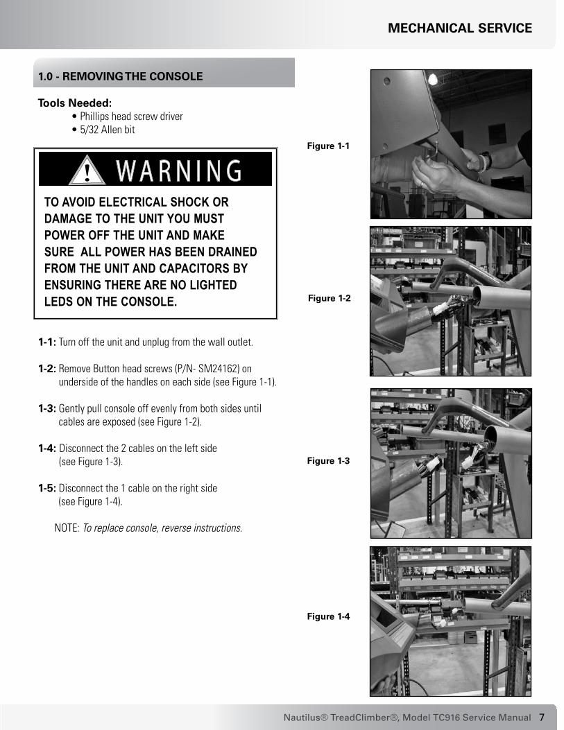
1.0 - removInG the conSole
tools needed: • Phillips head screw driver • 5/32 Allen bit
1-1: Turn off the unit and unplug from the wall outlet.
1-2: Remove Button head screws (P/N- SM24162) on underside of the handles on each side (see Figure 1-1).
1-3: Gently pull console off evenly from both sides until cables are exposed (see Figure 1-2).
1-4: Disconnect the 2 cables on the left side (see Figure 1-3).
1-5: Disconnect the 1 cable on the right side (see Figure 1-4).
NOTE: To replace console, reverse instructions.
figure 1-1
figure 1-2
figure 1-3
figure 1-4
to Avoid electricAl shock or dAmAge to the unit you must power off the unit And mAke sure All power hAs been drAined from the unit And cApAcitors by ensuring there Are no lighted leds on the console.

�
mechanIcal ServIce
2.0 - acceSSInG the conSole for proGrammInG
tools needed: • Phillips head screw driver
2-1: Turn off the unit.
2-2: Remove six (6) screws (P/N - SM41271) from back side of console to remove cover and gain access for programming (see Figure 2-1 and Figure 2-2).
2-3: Attach FISP connector for software programming to this connection (see Figure 2-3).
2-4: Turn on the unit.
2-5: The LED on the FISP will blink momentarily, then stay on solid.
2-6: Turn off the unit.
2-7: Remove FISP connector, replace cover and reattach with six (6) screws (P/N - SM41271).
figure 2-2: exposed console circuit board.
figure 2-1
3 screws per side
figure 2-3

9Nautilus® TreadClimber®, Model TC916 Service Manual
3.0 - removInG rear Step
tools needed: • Phillips head screw driver • 5/32 Allen bit
3-1: Unplug the unit from the power source and ensure that all power has been drained from the unit.
3-2: Remove two (2) middle screws from Rear Step Cover (see Figure 3-1).
3-4: Lift and slide step cover plate back to remove (see Figure 3-2).
3-3: Remove four (4) screws from Step Weldment (see Figure 3-3).
3-5: Replace rear cover by sliding back into place and re-installing four (4) outer screws.
3-6: Place Step cover onto Step weldment and reattach with two (2) screws (see Figure 3-2 and Figure 3-1).
Removing the step cover plate provides access to the I/O cables needed for the removal of the uprights.
to Avoid electricAl shock or dAmAge to the unit you must power off the unit And mAke sure All power hAs been drAined from the unit And cApAcitors by ensuring there Are no lighted leds on the console.
mechanIcal ServIce
figure 3-2
figure 3-1
Two Middle Screws
figure 3-3
Four outer Screws

10
mechanIcal ServIce
4.0 - vSD aSSeMbly gRouNDiNg
parts affected:• Front Trim Cover - P/N: SM17652• Right Pan Cover - P/N: SM17653• Right Side Cover - P/N: SM17655• VSD Assembly, TC916 - P/N: SM17688• Flat Washer, 1/4 ID x 5/8 OD - P/N: SM22047• Screw, .250-20 x .75, HX Wash HD -
P/N: SM27594
tools needed: • 1/8 Allen Bit • 3/8 inch Socket or Open End Wrench
to Install new vSD Ground Improvement:
4-1: Adjust Right Treadle to maximum step height. 4-2: Remove three (3) screws from Front Trim Cover (P/N
- SM17652). See Figure 1.
4-3: Remove four (4) screws from Right Side Cover (P/N - SM17655). See Figure 2.
4-4: Remove two (2) screws from Right Pan Cover to access the VSD Assembly (see Figure 3 and Figure 4).
cautioN: eNSuRe that all lightS aRe off oN the vSD aSSeMbly befoRe coNtiNuiNg - otheRwiSe, you May DaMage the boaRD.
4-5 Disconnect and mark cables (for reconnecting in later step) from the VSD board.
figure 1:
figure 2:
to avoid the risk of electrocution, shock or mechanical injury, before performing this maintenance, ensure that the machine is unplugged.

11Nautilus® TreadClimber®, Model TC916 Service Manual
mechanIcal ServIce
4-6: Remove the two (2) VSD Bracket Screws (P/N - SM27594), then remove the VSD Assmebly (see Figure 4).
4-7: Position the new VSD Assembly in place and attach with the two (2) bracket screws.
4-8: Reconnect the previously marked cables to the VSD Assembly.
4-9: Reattach all covers and verify that all machine functions are working properly.
figure 3:
figure 4:
vSD bracket Screws

1�
5.0 - removInG uprIGhtS
tools needed: • 1/8 Allen bit • 5/32 Allen bit • 3/4 inch Socket • Phillips head screw driver
5-1: Remove the Front Trim Cover (P/N - SM17652), Left Side Cover (P/N - SM17656), Left Pan Cover (P/N - SM17654) and Right Side Cover (P/N - SM17655), Right Pan Cover (P/N - SM17653).
5-2: Remove the Rear Step Cover and weldment (see Figure 5-1).
5-3: Remove the Rear Plastic Cover (P/N - SM17659 to access the Upright Cables. (See Figure 5-2 and Figure 5-4.)
5-4: Disconnect three cables as follows:
A) From the VSD Board. See Figure 5-3.
figure 5-1
figure 5-2
figure 5-3: I/o connectors.
mechanIcal ServIce
detAching And moving the upright portion of this product requires two people! you must hAve A minimum of two people to properly support the heAvy upright structure so the console does not fAll And cAuse dAmAge to the unit.
to Avoid electricAl shock or dAmAge to the unit you must power off the unit And mAke sure All power hAs been drAined from the unit And cApAcitors by ensuring there Are no lighted leds on the console.
cable connector

1�Nautilus® TreadClimber®, Model TC916 Service Manual
figure 5-4
figure 5-5 figure 5-6: lower plastic parts.
figure 5-7 figure 5-8
B) From the Encoder Assembly PC board (Not shown).
NOTE: The Encoder is under the Treadles and you will have to reach into the machine to disconnect.
C) From the Hydraulic Cylinder. See Figure 5-5.
5-5: Remove the Right Lower Cover (P/N - SM17657) and Left Lower Cover (P/N - SM17658). See Figure 5-6 and 5-7.
5-6: Remove four (4) upright weldment bolts (see Figure 5-8).
Cylinder control cables located
here.
mechanIcal ServIce

1�
6.0 - removInG BaSe plaStIc
tools needed: • Phillips head screw driver • 1/8 Allen bit
6-1: Remove three (3) front plastic screws (see Figure 6-1).
6-2: Remove right and left side plastic covers - four (4) screws each side (see Figure 6-2).
6-3: Remove right and left side pan covers - two (2) screws each side (see Figure 6-3 and Figure 6-4).
figure 6-1
figure 6-2
figure 6-3
figure 6-4: pan without
covers.
mechanIcal ServIce
to Avoid electricAl shock or dAmAge to the unit you must power off the unit And mAke sure All power hAs been drAined from the unit And cApAcitors by ensuring there Are no lighted leds on the console.

1�Nautilus® TreadClimber®, Model TC916 Service Manual
7.0 - Belt tenSIon anD alIGnment
parts affected: • Left Treadle Assembly - P/N 17623 • Right Treadle Assembly - P/N 17617 • Treadle Belt - P/N - SM17860
tools needed: • 5/16 Allen bit Belt alignment and tensioning adjustments (see Figure 1).
NOTE: See Figure 1 for belt and tensioning adjustment screws. The adjustments are the same on the right and left side of the machine.
To check for proper belt alignment:
7-1: Operate TreadClimber® machine so belt is running at 2.5 - 3 mph (4 - 4.8 km/h).
7-2: Belt is aligned when 1/8” (3.2 mm) of roller is showing (see Figure 2).
7-3: Tightening alignment screw clockwise moves belt out, loosening screw counter-clockwise moves belt in.
To check for proper belt tension:
7.1-1: Tension is correct when the gap between the treadles is even and centered. See Figure 3 for an example of INCORRECT tension.
7.1-2: Tighten (clockwise turn) or loosen (counter-clockwise turn) tensioning adjustment located at the end of the treadle.
To completely loosen belt if you want to start from scratch:
7.2-1: Totally loosen alignment screw by turning counter-clockwise.
7.2-2: Loosen tensioning screw by turning counter-clockwise.
figure 1
figure 2
figure 3
alignment adjustment
Tensioning adjustment
Tension is too tight, treadle guards are rubbing. To correct loosen tensioning
adjustment screw.
Belts are correctly aligned when 1/8 inch of roller is showing.
mechanIcal ServIce

16
8.0 - Belt anD DecK replacement
tools needed: 7/16 & 3/4 Wrench or Socket 3/8 Allen Socket 1/8, 5/32 & 5/16 Allen Wrench Phillips screwdriver wood blocks 4-6 inch (10-15 cm) thick
8-1: Remove rear cover and rear step (see Figure 1 and Figure 2).
8-2: Remove side pivot covers, side frame covers, front cover, bottom frame covers and treadle covers (see Figure 1).
8-3: Loosen four 1/2” - 13 bolts holding uprights to frame using 3/4 socket or wrench.
8-4: Remove pivot casting bolts with 5/32 Allen wrench.
8-5: Lift console upright to remove pivot castings.
8-6: Relieve all tension on the belt by completely loosening the alignment screw and then the tensioning screw.
8-7: Remove end casting with front roller using 5/16 Allen wrench (see Figure 3).
8-8: Remove deck screws with a 7/16 socket or wrench.
8-9: Remove deck (see Figure 4).
8-10: Brace treadles with blocks 4-6 inches (10-15 cm) thick (see Figure 5).
8-11: There are 2 treadle bolts and 4 treadle pivot bolts on each side. Remove these 6 bolts on one side, and loosen the 2 treadle bolts and remove the 4 pivot bolts using a 3/8 Allen and socket wrench (see Figure 6).
note: Remove one belt at a time. Replace the bolts, deck and belt before proceeding to the other side.
8-12: Lift treadle to create clearance for walk belt to slide between upright and end of roller (see Figure 7).
8-13: Replace belt and deck using the reverse order of steps 11 through 1.
rear cover
rear Step
Side pivot coversSide frame covers
front cover
Bottom frame covers
treadle covers: 4 covers total - top/bottom, and left/right.
figure 1
mechanIcal ServIce
alwayS uNPlug the tReaDcliMbeR® befoRe PeRfoRMiNg aNy tReaDle RePaiR! uSe cautioN wheN woRkiNg oN the Deck oR RePlaciNg the beltS. SeRiouS iNjuRy to fiNgeRS aND haNDS May occuR if the tReaDleS aRe Not PRoPeRly SuPPoRteD with blockS.

1�Nautilus® TreadClimber®, Model TC916 Service Manual
Belt anD DecK replacement contInueD:
figure 2: rear cover and rear step removed.
figure 3: removing end casting with allen wrench.
figure 5: Brace treadles with wooden blocks.
figure 6: remove treadle bolts & pivot bolts; 4 bolts per side.
figure 4: remove deck. figure 7: lift treadle to create clearance.
mechanIcal ServIce

1�
mechanIcal ServIce
9.0 - treaDle aDJuStment trouBleShootInG
parts affected: • Treadle Assembly • Hydraulic Cylinder
tools needed: • Phillips Screwdriver • Hex Key • Socket Wrench • Flat Screwdriver
troubleshooting treadle Steps:
a: DetermInInG If there IS a proBlem WIth the hyDraulIc cylInDer (eIther aIr In the SyStem or contamInantS In the oIl anD valveS), or In the connectInG harDWare:
NOTE: Two people are required to complete this step. One person standing on the treadles, while the other person adjusts the encoder.
9a-1: Disconnect the two leads from the hydraulic cylinder. This will ensure that the hydraulic cylinder valve should be closed (see Figure A-1).
9a-2: With the treadles in the locked position, pull up and down on both the right and left treadles (see Figure A-2).
If the right treadle is loose (moves more than ½”) and the left treadle is solid, this points to loose hardware. Go to Step 9A-4 in Section A.
If both right and left treadles are loose, then the problem could be loose hardware or a bad cylinder.
figure a-1
figure a-2
figure a-3
figure a-4

19Nautilus® TreadClimber®, Model TC916 Service Manual
mechanIcal ServIce
figure a-5
figure a-6
9a-3: Check the cylinder by feeling the shaft of the cylinder and pulling up and down on the left treadle. If the cylinder shaft moves in and out of the cylinder body by more than an 1/8th inch (3.2 mm), then the cylinder will need to be replaced.
9a-4: If the problem is not in the cylinder, then check the hardware at the following locations and tighten as necessary:
a) On the rod-end entering the cylinder, the jam nut should be tight to the rod-end, and there should only be 2 or 3 threads showing on the opposite side of the jam nut. This insures that the rod-end is fully engaged in the cylinder.
b) The connection between the rod-end and the
dependency weldment. See Figure A-6. Tighten as necessary.
c) The connection between the dependency and
the rod-end on the opposite (right) side (see Figure A-4 and A-5).
d) The center bolt at the center of the dependency weldment (see Figure A-6).
e) Check both the horizontal and the vertical bolts connecting the cylinder to the coupler and the coupler to the weldment of the pan. The bolts should be torqued to 75 ftlbs (105 Nm). See Figure A-7.
figure a-7

�0
mechanIcal ServIce
B: If the proBlem IS not In the hyDraulIc cylInDer or the connectInG harDWare, then perform the folloWInG electronIc anD SoftWare checKS:
9B-1: Turn the unit on. Move the treadles up and down until they come to a locked position.
9B-2: If the treadles do not come to a locked position within 2 to 4 steps, then position the treadles level. Turn the power off. Wait 10 seconds, then turn the power on. Move the treadles up and down until they come to a locked position.
9B-3: If the treadles still do not come to a locked position, then check the treadle center position on the encoder PCB, as follows:
a) Remove the rear step. Enter diagnostic mode. From the Intro screen, press [Speed UP] [6] [ENTER]. The display will read “DIAGNOSTIC”.
b) Press the [Speed UP] or [Speed DOWN] keys to scroll through the options until “TREADLE CENTER” is displayed. Press [ENTER]. This will release the treadles to allow them to be moved by hand.
c) Slowly move the treadles up and down while looking at the encoder PCB mounted in the center of the dependency mechanism. There is a light on the PCB. Note the position of the treadles when the light on the PCB comes on. The treadles should be parallel within 1 inch (2.5 cm) of each other when the PCB light comes on (see Figure B-1).
d) If the treadles are not parallel when the encoder PCB light comes on, then the large encoder wheel will need to be adjusted. Go to section C of this section in the Service Manual to re-center the encoder wheel. Be sure to verify that the large encoder wheel is firmly fixed to the dependency
figure B-1

�1Nautilus® TreadClimber®, Model TC916 Service Manual
mechanIcal ServIce
c: to re-center the larGe encoDer Wheel attacheD to the DepenDency mechanISm, folloW theSe StepS:
9c-1: Loosen the set screw. Be sure that the treadles are level.
9c-2: SloWly rotate the large encoder wheel in one direction by hand or use a small flat-blade screwdriver on the teeth of the encoder wheel. Rotate the wheel until the light comes on the encoder PCB.
9c-3: With the treadles level and the encoder light on, tighten the set screw holding the large encoder wheel in place (see Figure C-1).
9c-4: Go to section D to make sure that the large encoder wheel is not slipping during treadle movement.
figure c-1
mechanism. This can be checked by verifying the number of encoder counts in the diagnostic software. See section D of this bulletin to check the encoder counts.
e) If the treadles are parallel or within 1 inch of parallel when the encoder PCB light comes one, reset the treadle center in the software mode. Go to Section E of this bulletin to reset the treadle center in the software mode.

��
mechanIcal ServIce
D: to checK the encoDer ranGe of movement anD to maKe Sure the larGe encoDer Wheel IS not SlIppInG DurInG movement, folloW theSe StepS:
9D-1: From the Intro screen, press [Speed UP] [6] [EN-TER]. The display will read “DIAGNOSTIC”. Press the [Speed UP] or [Speed DOWN] keys to scroll through the options until “TREADCLIMBER” is displayed. Press [ENTER].
9D-2: The top line of the display will read: “ENCODER - XX” (see Figure D-1). Press the [9] key. The PWM value, which is on the lower line center position, will change from 255 to 189, and the treadles will be free to move up and down.
9D-3: Shift your weight to the left side, allowing the left treadle to fall all the way to the bottom. With the left treadle held at the bottom, note the number displayed on the top line, far right. It should read in the range between [ - 30 ] and [ - 50 ]. Remem-ber the number.
9D-4: Next, shift your weight to the right side, allowing the right treadle to fall all the way to the bottom. The number displayed on the top line, far right should read in the range between [ 30 ] and [ 50]. Remember the number.
9D-5: Calculate the total range between the two num-bers. The absolute value of the negative number (left side down) added to the positive number (right side down), represents the total encoder range of motion. This number should be in the range between 70 and 90 total counts.
9D-6: If the range is less than 70, check to make sure the large encoder wheel is not slipping.
figure D-1
to check if the encoder wheel is slipping, slowly move the treadles up and down. The encoder value displayed will hesitate and not count up or down. In other words, the encoder value will not change, even though there is movement in the treadles. If the encoder value does not change during movement of the treadles, then the encoder wheel is slipping and needs to be tightened or replaced.

��Nautilus® TreadClimber®, Model TC916 Service Manual
mechanIcal ServIce
e: to reSet the treaDle center In SoftWare to match the treaDle center on the encoDer, folloW theSe StepS:
9e-1: From the Intro screen, press [Speed UP] [6] [ENTER]. The display will read “DIAGNOSTIC”. Press the [Speed UP] or [Speed DOWN] keys to scroll through the options until “TREADLE CENTER” is displayed. Press [ENTER].
9e-2: The top line of the display will read: “VIRTUAL CENTER - XX” (see Figure E-1). With the treadles held parallel, press the [STOP] key. The number on the display will be used by the software for the center point position. When STOP key is pressed the number will change to a value between 0 to 255. This means the treadle center in the software has been recalibrated to match the center position of the encoder.
9e-3: Press [CLEAR] twice to exit the Diagnostic mode. Move the treadles up and down until the treadles lock. Verify that the treadles lock parallel to each other or within 1” of parallel.
9e-4: If the treadles do not lock parallel or close to parallel, then 1) recheck the center position on the encoder PCB (section B); 2) recheck the encoder range (section D); 3) recheck the treadle center in software (section E).
figure e-1

��
mechanIcal ServIce
10.0 - replacement of pIvot coverS
parts affected: • Right Pivot Cover - P/N 17660• Left Pivot Cover - P/N 17661
tools needed:
See Figure 1 for Steps 10-1 thru 10-4.
10-1: Remove Rear Step (P/N -17733) and Step Plate (P/N - 17591).
10-2: Remove Rear Plastic Cover (P/N - 17659).
10-3: Remove right Treadle Cover (P/N - SM17731 and P/N - SM17666), then remove the left Treadle Cover (P/N - SM17332 and P/N - 17667).
10-4: Remove right and left Upright Lower Plastic Pivot Covers (P/N - SM17657 and P/N - 17578). figure 1
Rear Step
Rear Plastic Cover
Lower Plastic Cover
Lower Plastic Cover
Treadle Top Cover
Treadle Top Cover
Upright AttachmentBolts
• 3/16 Allen Wrench• 5/32 Allen • 1/8 Allen• Phillips Screwdriver
• 3/4 inch Socket• 3/4 inch Wrench or Open Ended Wrench• Wedge support or flat head screwdriver to use as
a wedge

��Nautilus® TreadClimber®, Model TC916 Service Manual
mechanIcal ServIce
10-5: Loosen 4 inside bolts (2 on each side) that attach the upright (P/N - 17626) to base frame (see Figure 2).
10-6: Slide the upright (P/N - 17626) backwards, away
from the front of the unit to expose the right and left pivot covers. Secure in the back position (see Figures 1 &2).
10-7: Remove right and left pivot covers (P/N - 17660 & 17661). This may require a twisting motion (see Figure 3). Install replacement pivot cover in its place.
10-8: Reassemble the unit in reverse order from Step 6 to Step 1: Slide the uprights forward into place; tighten the four inside bolts; reinstall the right and left lower plastic covers; reinstall the right and left treadle top covers; reinstall rear plastic cover; and reinstall rear step and step plate weldment.
1/2” to 3/4” MAX
Slide Uprights Back
1/2 INCH MAXIMUM
Left Pivot Cover
figure 3
figure 2
Do Not ReMove boltS coMPletely. to Do So will cauSe the uPRight SuPPoRtS to fall ReSultiNg iN DaMage to the uNit aND PoSSible iNjuRy to byStaNDeRS. the boltS MuSt Not be backeD beyoND a MaXiMuM DiStaNce of 1/2 iNch. See figuRe 2.
SliDiNg the uPRightS May ReQuiRe aSSiStaNce. Do Not atteMPt to lift the uNit.
(1.3 CM)

�6
11.0 - replacement of hyDraulIc cylInDerS
parts affected: • Front Cover - P/N 17652• Left Side Cover - P/N 17656• Left Lower Pan Cover - P/N 17654• Left Lower Treadle Cover - P/N 17665• Left Top Treadle Cover - P/N 17667• Bolt - P/N 17677• Cylinder Pivot Weldment - P/N 17586• Hydraulic Cylinder - P/N SM17810
tools needed: • Phillips screw driver (long & short shaft)
• Loctite 242 (blue) • 3/8 Allen wrench • 3/4 inch Socket • 3/4 inch Open End Wrench • #15 Torque wrench
to remove the hydraulic cylinder: Before performing the following steps make sure that you note the location and position of all hardware that is removed.
11-1: Stand on the right treadle to raise the left treadle to full height.
11-2: Turn the power off and unplug the machine from the wall outlet.
See figure 1 for Steps 3 to 5.
11-3: Remove the Front Cover (P/N - 17652).
11-4: Remove the Left Side Cover (P/N - 17656) and Left Side Pivot Cover.
11-5: Remove the Left Lower Pan Cover (P/N - 17654).
11-6: Unplug two lead wires from cylinder.
11-7: Remove Left Lower Treadle Cover (P/N - 17665).
11-8 Tilt the machine upward slightly and brace with a block of wood under the machine to hold in place.
mechanIcal ServIce
figure 1
front cover
left SIDe cover
left loWer pan cover
left SIDe pIvot cover

��Nautilus® TreadClimber®, Model TC916 Service Manual
11-9: With a 3/8 inch Allen wrench and 3/4 inch wrench placed on the Nut (P/N - SM22893) under the frame, loosen Bolt (P/N - SM17677) from the Cylinder Mount Weldment (P/N - SM17586) and bracket attachment welded to the base frame.
11-10: Remove the bolt holding the cylinder to the dependency link using a 3/4 inch open-end wrench and 3/4 inch socket (see Figure 2).
11-11: Use a 3/4 inch socket and 3/4 inch open-end wrench to loosen Bolt (P/N - SM26669) from the cylinder mount weldment (see Figure 10-3).
11-12: Remove the two Bolts previously loosened in Step 11-9 and 11-10.
11-13: Remove the hydraulic cylinder. Mark the hydraulic cylinder to show the reason for removing.
to Install the new hydraulic cylinder:
11-14: Attach bolt, washers, and nut into the Cylinder Mount Weldment (P/N - SM17867) and new Hydraulic Cylinder (P/N - SM17810), then tighten using a 3/4 inch socket and 3/4 inch Open-end wrench (see Figure 4 - Bolt B).
11-15: Slide new hydraulic cylinder with attached cylinder mount into the bracket attachment welded to the base frame and loosely tighten with Bolt (P/N - SM17677), washer, and Nut (P/N - SM22893). See Figure 4 - Bolt C.
11-16: Attach and tighten the hydraulic cylinder to the dependency link using a 3/4 inch Open-end wrench and 3/4 inch socket with Bolt (P/N - SM25412), washers, and nut (see Figure 4 - Bolt A).
11-17: Return to bolts in Steps 11-1, 11-2 and 11-3 of Install the New Hydraulic Cylinder process. Tighten bolts in order of A, C, B (see Figure 4) to 75 Ft Lbs (100 Nm) with a Torque wrench.
11-18: Reconnect the plugs that were disconnected in Step 11-6 of the Removal Process to the hydraulic cylinder.
11-19: Replace the machine covers in reverse order of the Removal Process from Steps 11-7 to 11-3.
mechanIcal ServIce
figure 2: Removing the bolt connecting the hydraulic cylinder to
the Dependency linkage.
figure 3: Removing bolt connecting cylinder Mount weldment from
the hydraulic cylinder.
figure 4: hydraulic cylinder bolt locations:
note: �All�bolts�are�at�75�ft�lbs�and�should�be�tightened�in�A,�C,�B�order�always.�
a
a
c
B
��
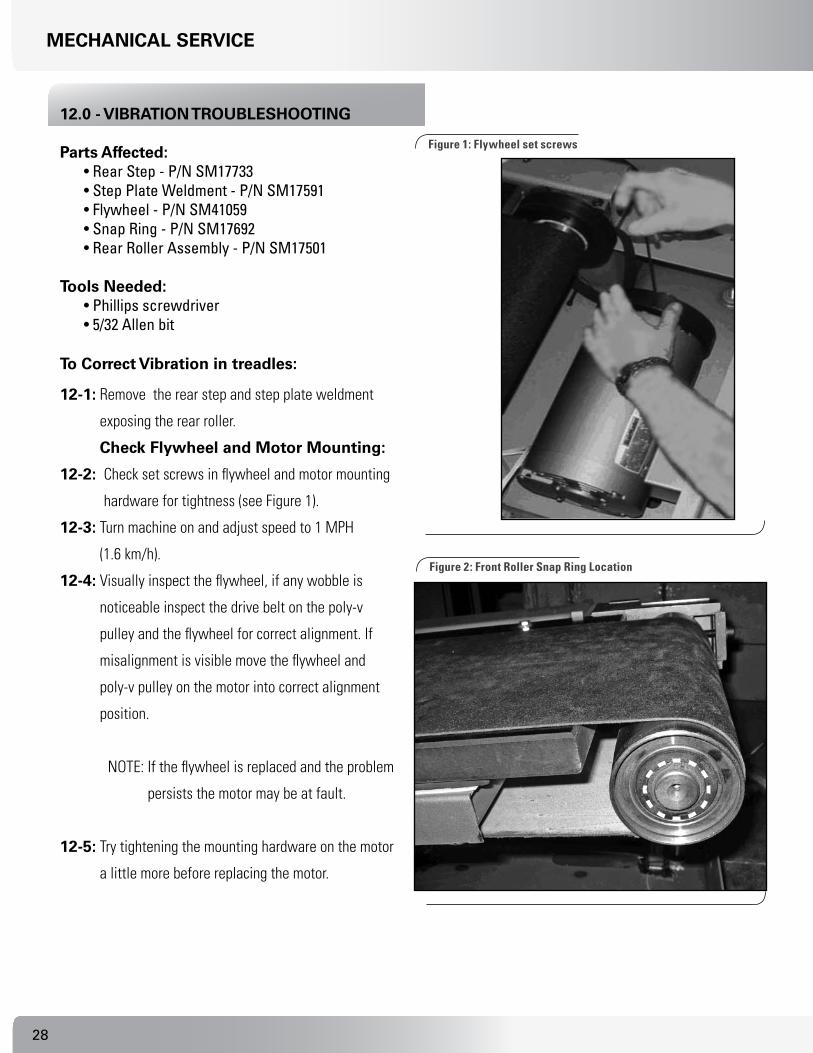
12.0 - vIBratIon trouBleShootInG
parts affected: • Rear Step - P/N SM17733• Step Plate Weldment - P/N SM17591• Flywheel - P/N SM41059• Snap Ring - P/N SM17692• Rear Roller Assembly - P/N SM17501
tools needed: • Phillips screwdriver • 5/32 Allen bit
to correct vibration in treadles:
12-1: Remove the rear step and step plate weldment
exposing the rear roller.
check flywheel and motor mounting:
12-2: Check set screws in flywheel and motor mounting
hardware for tightness (see Figure 1).
12-3: Turn machine on and adjust speed to 1 MPH
(1.6 km/h).
12-4: Visually inspect the flywheel, if any wobble is
noticeable inspect the drive belt on the poly-v
pulley and the flywheel for correct alignment. If
misalignment is visible move the flywheel and
poly-v pulley on the motor into correct alignment
position.
NOTE: If the flywheel is replaced and the problem
persists the motor may be at fault.
12-5: Try tightening the mounting hardware on the motor
a little more before replacing the motor.
mechanIcal ServIce
figure 1: flywheel set screws
figure 2: front Roller Snap Ring location

�9Nautilus® TreadClimber®, Model TC916 Service Manual
check the front roller Snap ring:
12-6: Verify that the snap ring on the front rollers is in place
properly (see Figure 2).
NOTE: This can be seen more easily with the treadle
guards removed.
check the rear roller pulley:
12-7: Check the rear roller pulley, if the pulley wobbles it
was pressed on incorrectly and the entire roller needs
to be replaced.
12-8: Check the center of the rear roller (where the two
halves join) if there is any wobble the roller was not
assembled correctly and needs to be replaced.
mechanIcal ServIce

�0
carDIo conSole coDeS
General Information:• Press the UP Speed/Load key [], the numeric [ # ] key, and then press the [ENTER] key once to enter this mode.
Pressing [] or [] forwards or backs up through the selections. Pressing [ENTER] then selects that item. Enter values then press the [ENTER] key again to store the value.
• Once in console codes mode, pressing [] [] forwards or backs up through the selection, pressing [ENTER] then selects that item. Pressing [CLEAR] exits any of the special access modes.
• Pressing [CLEAR] twice will exit the Console Service Mode.
Workout Default console codes:
[] [ 2 ] [ enter ] “DefaultS” [] [ ENTER ] “ENTER WT XXX” [] [ ENTER ] “ENTER LEVEL 1 TO 20” [] [ ENTER ] “ENTER TIME 5 TO 99” [] [ ENTER ] “ENTER AGE 10 TO 99” [] [ ENTER ] “CHR PERCENT XX” [] [ ENTER ] “ENTER SPEED XX.X” [] [ ENTER ] “QUICK SPEED XX.X”
[] [ 3 ] [ enter ] “cuStomIZe” [] [ ENTER ] “MAX TIME” [] [ ENTER ] “COOL DOWN” [] [ ENTER ] “CHANGE UNITS” [] [ ENTER ] “HR INPUTS”[] [ ENTER ] “SELECT STATS” [] [ ENTER ] “LANGUAGE” [] [ ENTER ] “UPPER CONTRAST ADJ” [] [ ENTER ] “LOWER CONTRAST ADJ” [] [ ENTER ] “MAX SPEED” [] [ ENTER ] “ENABLE MAG KEY”[] [ ENTER ] “AUTO STOP” [] [ ENTER ] “SET DEFAULTS“
[] [ 4 ] [ enter ] “machIne StatuS”[] [ ENTER] “ RUN HOURS” [] [ ENTER ] “ WORKOUTS” [] [ ENTER ] “ DISTANCE”[] [ ENTER ] “ CONSOLE VERSION” “Displays Console Version #”[] [ ENTER ] “DEVICE TYPE” ”Displays Machine Type”[] [ ENTER ] “ TM DRIVE VER” [] [ ENTER ] “ MAINT HOURS”
NOTE: SEvERAl COdES mAy bE INCludEd IN THE CONSOlE COdES lIST THAT dO NOT Apply TO THE TREAdClImbER® FuNCTIONS.

�1Nautilus® TreadClimber®, Model TC916 Service Manual
carDIo conSole coDeS
Workout Default Console Codes Continued…
[] [ 5 ] [ enter ] “ r anD D” [] [ENTER] “ PROGRAM LOOP”[] [ENTER] “ COM TIMEOUT”
[] [ 6 ] [ enter ] “ DIaGnoStIc ”[] [ ENTER ] “DISPLAY TEST”[] [ ENTER ] “KEY TEST”[] [ ENTER ] “SERIAL PORTS”[] [ ENTER ] “A SENSOR B”[] [ ENTER ] “I/O TEST” [] [ ENTER ] “BUS VOLTS” [] [ ENTER ] “TREADLE CENTER”[] [ ENTER ] “TREADCLIMBER”
[] [ 7 ] [ enter ] “ maIntenance loGS ”[] [ ENTER ] “ERROR LOG”[] [ ENTER ] “MAINT HOURS”[] [ ENTER ] “QA ID”
[] [ 8 ] [ enter ] “ chanGe machIne” [ enter ]
For Treadmill Devices, the selections are:[] [ ENTER ] “TREADCLIMBER”[] [ ENTER ] “T916”[] [ ENTER ] “T914”[] [ ENTER ] “TC/TM CONFIG RQD”

��
carDIo conSole coDeS
��Nautilus® TreadClimber®, Model TC916 Service Manual
partS lISt
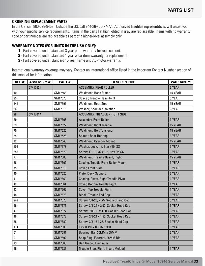
oRDeRiNg RePlaceMeNt PaRtS:In the US, call 800-628-8458. Outside the US, call +44-26-460-77-77. Authorized Nautilus representitives will assist you with your specific service requirements. Items in the parts list highlighted in gray are replaceable. Items with no warranty code or part number are replaceable as part of a higher-level assembly only.
waRRaNty NoteS (foR uNitS iN the uSa oNly):1 - Part covered under standard 3 year parts warranty for replacement. 2 - Part covered under standard 1 year wear item warranty for replacement.3 - Part covered under standard 15 year frame and AC-motor warranty.
International warranty coverage may vary. Contact an International office listed in the Important Contact Number section of this manual for information.
ref #: aSSemBly #: part #: DeScrIptIon: Warranty:
SM17501 ASSEMBLY, REAR ROLLER 3 YEAR
10 SM17568 Weldment, Base Frame 15 YEAR
25 SM17570 Spacer, Treadle Heim Joint 3 YEAR
141 SM17591 Weldment, Rear Step 15 YEAR
26 SM17615 Washer, Shoulder Isolation 3 YEAR
28 SM17617 ASSEMBLY, TREADLE - RIgHT SIDE
29 SM17508 Assembly, Front Roller 3 YEAR
69 SM17522 Weldment, Right Treadle 15 YEAR
70 SM17526 Weldment, Belt Tensioner 15 YEAR
34 SM17528 Spacer, Rear Bearing 3 YEAR
72 SM17543 Weldment, Cylinder Mount 15 YEAR
106 SM17578 Washer, Lock, Int. Star #10, SS 3 YEAR
255 SM17579 Screw, FH, 10-32 x .75, Hex Dr. SS 3 YEAR
77 SM17608 Weldment, Treadle guard, Right 15 YEAR
38 SM17609 Casting, Treadle Front Roller Mount 3 YEAR
75 SM17618 Cover, Front Slide 3 YEAR
40 SM17620 Plate, Deck Support 3 YEAR
41 SM17660 Casting, Cover, Right Treadle Pivot 3 YEAR
42 SM17664 Cover, Bottom Treadle Right 1 YEAR
43 SM17666 Cover, Top Treadle Right 1 YEAR
44 SM17673 Block, Treadle End Cap 3 YEAR
242 SM17675 Screw, 1/4-20, x .75, Socket Head Cap 3 YEAR
46 SM17676 Screw, 3/8-24 x 2.00, Socket Head Cap 3 YEAR
47 SM17677 Screw, .500-13 x 4.00, Socket Head Cap 3 YEAR
48 SM17678 Screw, 3/8-24 x 1.50, Socket Head Cap 3 YEAR
68 SM17680 Screw, 3/8-16 1.25, Socket Head Cap 3 YEAR
174 SM17685 Key, 0.190 x 0.190x 1.380 3 YEAR
51 SM17691 Bearing, Ball 30MM x 55MM 3 YEAR
91 SM17692 Snap Ring, External, 25MM Dia. 3 YEAR
73 SM17865 Belt guide, Aluminum
55 SM17731 Treadle Step, Right, Insert Molded 1 YEAR

��
partS lISt
ref #: aSSemBly #: part #: DeScrIptIon: Warranty:
98 SM17808 Screw, 10-32 x .375, SHCS, SS 3 YEAR
63 SM17809 Screw, 10-32 x .625, SHCS SS 3 YEAR
173 SM17815 Screw, Button HD Cap, 10-32 x 5 /8L 3 YEAR
68 SM17860 Belt, Treadclimber 1 YEAR
30 SM17862 Deck, Treadle 1 YEAR
228 SM22047 Washer, Flat 1/4 ID x 5/8 OD 3 YEAR
90 SM22098 Screw, .250-20 x 1.50, Hex Head Cap 3 YEAR
58 SM22276 Screw, #6 S.T. x .625 Hex OR TO 3 YEAR
254 SM25777 Screw, .250-20 x 1.00 Button Head 3 YEAR
88 SM27585 Washer, .406 x .812 x .065 Flat 3 YEAR
65 SM17623 ASSEMBLY, TREADLE LEFT 3 YEAR
29 SM17508 Assembly, Front Roller 3 YEAR
32 SM17523 Weldment, Left Treadle 15 YEAR
70 SM17526 Weldment, Belt Tensioner 15 YEAR
34 SM17528 Spacer, Rear Bearing 3 YEAR
72 SM17543 Weldment, Cylinder Mount 15 YEAR
106 SM17578 Washer, Lock, Int. Star #10, SS 3 YEAR
255 SM17579 Screw, FH, 10-32 x .75, Hex Dr. SS 3 YEAR
38 SM17609 Casting, Treadle Front Roller Mount 3 YEAR
75 SM17618 Cover, Front Slide 3 YEAR
40 SM17620 Plate, Deck Support 3 YEAR
37 SM17625 Weldment, Left Treadle guard 15 YEAR
78 SM17661 Casting, Cover, Left Treadle Pivot 3 YEAR
79 SM17665 Cover, Bottom Treadle Left 1 YEAR
80 SM17667 Cover, Top Treadle Left 1 YEAR
44 SM17673 Block, Treadle End Cap 3 YEAR
242 SM17675 Screw, 1/4-20, x .75, Socket Head Cap 3 YEAR
46 SM17676 Screw, 3/8-24 x 2.00, Socket Head Cap 3 YEAR
47 SM17677 Screw, .500-13 x 4.00, Socket Head Cap 3 YEAR
48 SM17678 Screw, 3/8-24 x 1.50, Socket Head Cap 3 YEAR
68 SM17680 Screw, 3/8-16 1.25, Socket Head Cap 3 YEAR
73 SM17685 guide, Belt 3 YEAR
51 SM17691 Bearing, Ball 30MM x 55MM 3 YEAR
91 SM17692 Snap Ring, External, 25MM Dia. 3 YEAR
101 SM17732 Treadle Step, Left, Insert Molded 1 YEAR
98 SM17808 Screw, 10-32 x .375, SHCS, SS 3 YEAR
63 SM17809 Screw, 10-32 x .625, SHCS SS 3 YEAR
173 SM17815 Screw, Button HD Cap, 10-32 x 5 /8L 3 YEAR
68 SM17860 Belt, Treadclimber 1 YEAR
30 SM17862 Deck, Treadle 1 YEAR
228 SM22047 Washer, Flat 1/4 ID x 5/8 OD 3 YEAR
90 SM22098 Screw, .250-20 x 1.50, Hex Head Cap 3 YEAR

��Nautilus® TreadClimber®, Model TC916 Service Manual
partS lISt
ref #: aSSemBly #: part #: DeScrIptIon: Warranty:
58 SM22276 Screw, #6 S.T. x .625 Hex OR TO 3 YEAR
254 SM25777 Screw, .250-20 x 1.00 Button Head 3 YEAR
88 SM27585 Washer, .406 x .812 x .065 Flat 3 YEAR
SM17626 ASSEMBLY, UPRIgHT
110 SM17702 Housing, Ergo, CHR, Top Left 1 YEAR
111 SM17703 Housing, Ergo, Bottom Left 1 YEAR
112 SM17704 Housing, Ergo, CHR, Top Right 1 YEAR
113 SM17705 Housing, Ergo, Bottom Right 1 YEAR
114 SM17739 Keypanel, Ergo, TC916 1 YEAR
256 SM40639 Screw, 6-32 x .438 Lg Shc 3 YEAR
121 SM41034 Contact Plate, CHR 1 YEAR
122 SM41112 Housing, Ergo, Bottom Center 1 YEAR
123 SM41158 End Cap, Handle Barm Molded 1 YEAR
SM41169 Cable Harness 3 YEAR
SM41180 Heart Rate Detection Module 3 YEAR
SM41193 Cable Harness 3 YEAR
257 SM41268 Screw, 6-32 x .3125, SHCS 3 YEAR
SM41443 Cable Harness 3 YEAR
102 SM17793 Assy, Weldment, Upper Right
252 SM17794 Assy, Weldment, Lower Right
N/A SM17824 Assy, Harness Extension, Console
N/A SM17826 Assy, Harness, Extension, VSD
N/A SM17775-007 Intrnl/Extrnl Washer .375
N/A SM25796 Screw, .375-16 x 1.00, BH, SS
SM41449 Assy, Ergo Bar, Touch Sensor 1 YEAR
27 SM17631 Belt, Drive, Poly-V 3 YEAR
SM17640 ASSEMBLY, TREADLE DEPENDENCY
129 SM17551 Weldment, Treadle Rocker 15 YEAR
135 SM41048 Bearing, Ball, 25MM x 52MM 3 YEAR
130 SM17639 Shaft, Rocker Pivot 3 YEAR
52 SM17692 Snap Ring, External, 25MM Dia 3 YEAR
128 SM17548 gear, 120T (48DP), Cut 3 YEAR
251 SM17742 Bracket, gear Locking 3 YEAR
250 SM24088 Washer, #10 Split Lock 3 YEAR
136 SM17641 ASSEMBLY, DEPENDENCY LINK
146 SM17651 Bumper, Rubber Stop 3 YEAR
147 SM17652 Cover, Front Trim 1 YEAR
148 SM17653 Cover, Right Pan 1 YEAR
149 SM17654 Cover, Left Pan 1 YEAR
150 SM17655 Cover, Right Side 1 YEAR
151 SM17656 Cover, Left Side 1 YEAR
152 SM17657 Cover, Right Pivot 1 YEAR

�6
partS lISt
ref #: aSSemBly #: part #: DeScrIptIon: Warranty:
153 SM17658 Cover, Left Pivot 1 YEAR
154 SM17659 Cover, Lower Front Step 1 YEAR
107 SM17668 Cover, Top Upright Right 1 YEAR
108 SM17669 Cover, Top Upright Left 1 YEAR
155 SM17670 ASSEMBLY, CONSOLE TC916 3 YEAR
46 SM17676 Screw, 3/8-24 x 2.00, SHC 3 YEAR
177 SM17682 Screw, 3/8-16 x 1.00 Button Head Cap 3 YEAR
172 SM17683 Screw, .500-13 x 3.25, Hex Head Cap 3 YEAR
175 SM17686 Leveler, 0.500 inches-13 x 0.875 Tall 3 YEAR
178 SM17688 ASSMEBLY, VSD, TC9.16 3 YEAR
260 - INT SM41404 Assembly, Choke, 6MH, International Units
253 SM17689 Decal, Step Warning 1 YEAR
258 SM17695 Screw, #10-32 x 0.375, Flat Head, Phil 3 YEAR
188 SM17719 ASSEMBLY, CONFIg PLATE, TC9 SERIES (USA Domestic Units) 3 YEAR
188 - INT SM17823 Assembly, Config Plate, 230V, International Units TC9
63 SM28214 Screw, 10-32 x .750 Socket HDCP
125 SM17569 Assy., Treadle Mount
143 SM17733 Rear Step, Insert Molded 1 YEAR
63 SM17809 Screw, 10-32 x .625, SHCS, SS 3 YEAR
126 SM17810 ASSMEBLY, CYLINDER, HYD. CONTROL, TC916
173 SM17815 Screw, Button Hd Cap, 10-32 x 5/8L 3 YEAR
233 SM22030 Washer, 3/8 USS Flat 3 YEAR
228 SM22047 Washer, Flat 1/4 ID x 5/8 OD 3 YEAR
132 SM22091 Washer, .50 SAE Flat 3 YEAR
133 SM22222 Washer, Split Lock, .50 3 YEAR
138 SM22893 Nut, Jam, .500-13 UNC, grade 8 3 YEAR
230 SM24643 Nut, .375-16, HX Jam, Nylon Insert 3 YEAR
237 SM27487 Drive Motor, AC Variable 15 YEAR
238 SM27562 Washer, Neoprene, .490x1.063x.09 3 YEAR
239 SM27577 Screw, M6 x 1.00 x 16 HHCAP 3 YEAR
240 SM27578 Washer, M6, Splitlock, Zinc 3 YEAR
241 SM27579 Washer, M6, Flat, Zinc 3 YEAR
226 SM27586 Spacer, Nylon, .125x .500 x 1.120 3 YEAR
SM40837 Assembly, Rotary Encoder 3 YEAR
8 SM41059 Flywheel, Cast, NTR 6000/7000 3 YEAR
9 SM17545 Assembly, Position Sensor TC
134 SM25412 Screw, .500-13 x 1.75 Hex HD CA
212 SM17737 Decal, Siderail, Right
210 SM17740 Decal, Rear Pivot
209 SM17736 Decal, Rear Hood
211 SM17738 Decal, Siderail, Left

��Nautilus® TreadClimber®, Model TC916 Service Manual
eXploDeD vIeWS
WorKInG WIth eXploDeD vIeWS
The reference numbers in the drawings on the following pages correlate to the reference numbers in the parts list on the preceding pages.
Base Frame with VSD Motor Control Board:
Base Frame with Drive Motor:8
27174
230
233
226
238
238
26
177
125
146
10
237
260

��
eXploDeD vIeWS
Base Frame with Dependency Link and Hydraulic System:
Dependency Link:

�9Nautilus® TreadClimber®, Model TC916 Service Manual
eXploDeD vIeWS
Console upright assembly, rear Step and Console assembly:
Treadle assembly:

�0
eXploDeD vIeWS
Base Frame Covers: (Right side as you stand on unit facing console.)
Base Frame Covers: (left side as you stand on unit facing console.)

�1Nautilus® TreadClimber®, Model TC916 Service Manual
eXploDeD vIeWS
Treadle Deck and Belt assembly: (left side as you stand on unit facing console.)
Treadle Deck and Belt assembly: (Right side as you stand on unit facing console.)

��
eXploDeD vIeWS
Treadle arm assembly: (Right side as you stand on unit facing console.)
Treadle arm assembly: (left side as you stand on unit facing console.)

��Nautilus® TreadClimber®, Model TC916 Service Manual
eXploDeD vIeWS
Treadle Covers - Top and Bottom: (left side as you stand on unit facing console.)
Treadle Covers - Top and Bottom: (Right side as you stand on unit facing console.)

��
eXploDeD vIeWS
roC Bar assembly:
Console upright and Cover assembly:

��Nautilus® TreadClimber®, Model TC916 Service Manual
eXploDeD vIeWS
rear Step and Support Platform:
�6
electronIc trouBleShootInG Summary1.
le
D
op
erat
ion
on
p
cB
as
Wh
at t
his
mea
ns
firs
t a
ctio
nS
eco
nd
act
ion
th
ird
act
ion
fou
rth
act
ion
Not
e ab
out u
se o
f Sta
tus
LEDs
: A s
ingl
e LE
D do
es n
ot s
how
the
com
plet
e pi
ctur
e of
an
erro
r con
ditio
n. R
evie
w th
e st
atus
of a
ll LE
Ds p
rior t
o de
cidi
ng w
hich
ass
embl
ies
to re
plac
e.
P51
Proc
esso
r Pcb
a:
DS1
Flas
hing
@ 1
Se
cond
Rat
eN
orm
al C
ondi
tion.
Nor
mal
con
ditio
n, n
o ac
tion
requ
ired.
DS1
Flas
hing
@
Irreg
ular
Rat
eP5
1 Pr
oces
sor P
CBA
Non
-op
erat
iona
l. Po
wer
off/
on tr
eadm
ill, s
ee if
pro
blem
sel
f-cl
ears
. Che
ck fo
r unp
lugg
ed o
r dam
aged
ca
bles
. Com
mun
icat
ion
cabl
e fro
m J
10 o
n P5
1 Pr
oces
sor P
CBA
is c
able
mos
t lik
ely
to
caus
e pr
oble
m.
Repl
ace
P51
Proc
esso
r PCB
A.
DS1
Off
Proc
esso
r is
non-
oper
atio
nal.
No
pow
er o
r P51
Pro
cess
or
PCBA
has
faile
d.
Pow
er o
ff/on
trea
dmill
, see
if p
robl
em s
elf-
clea
rs. C
heck
for u
nplu
gged
or d
amag
ed
cabl
es. C
omm
unic
atio
n ca
ble
from
J10
on
P51
Proc
esso
r PCB
A is
cab
le m
ost l
ikel
y to
ca
use
prob
lem
.
Chec
k LE
Ds o
n VS
D to
see
if V
SD h
as
pow
er.
Repl
ace
P51
Proc
esso
r PCB
A.
DS1
On C
ontin
uous
P51
Proc
esso
r PCB
A N
on-
oper
atio
nal.
Pow
er o
ff/on
trea
dmill
, see
if p
robl
em s
elf-
clea
rs.
Repl
ace
P51
Proc
esso
r PCB
A.
vSD
Pcb
a:
DS1
Flas
hing
@ A
ny
Rate
VSD
PCBA
is N
on-o
pera
tiona
l.Po
wer
off/
on tr
eadm
ill, s
ee if
pro
blem
sel
f-cl
ears
. Che
ck fo
r unp
lugg
ed o
r dam
aged
ca
bles
. Com
mun
icat
ion
cabl
e fro
m J
10 o
n P5
1 Pr
oces
sor P
CBA
is c
able
mos
t lik
ely
to
caus
e pr
oble
m.
Repl
ace
VSD
PCBA
.
DS1
Off
Wal
kbel
t mot
or is
OFF
.N
orm
al c
ondi
tion,
no
actio
n re
quire
d.
DS1
On C
ontin
uous
Wal
kbel
t mot
or is
ON
.N
orm
al c
ondi
tion,
no
actio
n re
quire
d.
DS2
Flas
hing
@ 1
Se
cond
Rat
eN
orm
al c
ondi
tion.
Nor
mal
con
ditio
n, n
o ac
tion
requ
ired.
DS2
Flas
hing
@
Irreg
ular
Rat
ePr
oces
sor i
n re
set i
s at
tem
ptin
g to
re-e
stab
lish
com
mun
icat
ion.
Pow
er o
ff/on
trea
dmill
, see
if p
robl
em s
elf-
clea
rs. C
heck
for u
nplu
gged
or d
amag
ed
cabl
es. C
omm
unic
atio
n ca
ble
from
J10
on
P51
Proc
esso
r PCB
A is
cab
le m
ost l
ikel
y to
ca
use
prob
lem
.
Repl
ace
VSD
PCBA
.Re
plac
e Co
nfig
urat
ion
Plat
e.
DS2
Off
Proc
esso
r in
rese
t or n
o co
mm
unic
atio
n.Po
wer
off/
on tr
eadm
ill, s
ee if
pro
blem
sel
f-cl
ears
. Che
ck fo
r unp
lugg
ed o
r dam
aged
ca
bles
. Com
mun
icat
ion
cabl
e fro
m J
10 o
n P5
1 Pr
oces
sor P
CBA
is c
able
mos
t lik
ely
to
caus
e pr
oble
m.
Repl
ace
VSD
PCBA
.Re
plac
e P5
1 Pr
oces
sor P
CBA.
Repl
ace
Conf
igur
atio
n Pl
ate.

��Nautilus® TreadClimber®, Model TC916 Service Manual
electronIc trouBleShootInG Summary1.
le
D
op
erat
ion
on
p
cB
as
Wh
at t
his
mea
ns
firs
t a
ctio
nS
eco
nd
act
ion
th
ird
act
ion
fou
rth
act
ion
DS2
On C
ontin
uous
Wal
kbel
t Ove
r cur
rent
Co
nditi
on.
This
err
or is
usu
ally
cau
sed
by e
xces
sive
dr
ag o
r fric
tion
on th
e de
ck. C
lose
ly in
spec
t th
e de
ck a
nd lo
ok fo
r sig
ns o
f exc
essi
ve
wea
r. If
need
ed re
plac
e th
e be
lt an
d de
ck.
Pow
er o
ff/on
tre
adm
ill, s
ee
if pr
oble
m s
elf-
clea
rs. C
heck
fo
r unp
lugg
ed o
r da
mag
ed c
able
s.
Repl
ace
VSD
PCBA
.Re
plac
e Dr
ive
Mot
or.
DS3
On C
ontin
uous
5V V
CC P
ower
Sup
ply
is
Oper
atio
nal.
Nor
mal
con
ditio
n, n
o ac
tion
requ
ired.
DS3
Off
5V V
CC P
ower
Sup
ply
is N
on-
oper
atio
nal.
Chec
k fo
r unp
lugg
ed o
r dam
aged
cab
les.
Ca
ble
goin
g to
P14
on
VSD
PCBA
is m
ost
likel
y to
cau
se p
robl
em.
Use
an o
hmm
eter
to
ver
ify C
onfig
PC
BA fu
ses
F3 a
nd
F4.
Repl
ace
VSD
PCBA
.Re
plac
e Co
nfig
urat
ion
Plat
e.
DS4
On C
ontin
uous
15V
Pred
rive
Pow
er S
uppl
y is
Op
erat
iona
l.N
orm
al c
ondi
tion,
no
actio
n re
quire
d.
DS4
Off
15V
Pred
rive
Pow
er S
uppl
y is
N
on-o
pera
tiona
l.Ch
eck
for u
nplu
gged
or d
amag
ed c
able
s.
Cabl
e go
ing
to P
20 o
n VS
D PC
BA is
mos
t lik
ely
to c
ause
pro
blem
.
Use
an o
hmm
eter
to
ver
ify C
onfig
PC
BA fu
ses
F3 a
nd
F4.
Repl
ace
VSD
PCBA
.Re
plac
e Co
nfig
urat
ion
Plat
e.
DS5
On V
ery
Brig
htDa
nger
! Hig
h Vo
ltage
Driv
e Bu
s Vo
ltage
Pre
sent
. N
orm
al p
ower
ed u
p co
nditi
on. D
o no
t han
dle
VSD
PCBA
unt
il LE
Ds g
o ou
t afte
r abo
ut 2
m
inut
es.
DS5
Off
High
Vol
tage
Driv
e Bu
s Ca
paci
tors
hav
e Di
scha
rged
.Hi
gh V
olta
ge D
rive
Bus
is d
isch
arge
d an
d VS
D PC
BA is
saf
e to
han
dle.
DS6
On V
ery
Brig
htDa
nger
! Hig
h Vo
ltage
Driv
e Bu
s Vo
ltage
Pre
sent
.N
orm
al p
ower
ed u
p co
nditi
on. D
o no
t han
dle
VSD
PCBA
unt
il LE
Ds g
o ou
t afte
r abo
ut 2
m
inut
es.
DS6
Off
High
Vol
tage
Driv
e Bu
s Ca
paci
tors
hav
e Di
scha
rged
.Hi
gh V
olta
ge D
rive
Bus
is d
isch
arge
d an
d VS
D PC
BA is
saf
e to
han
dle.
2. S
elf-
test
e
rro
r c
od
esW
hat
th
is m
ean
sfi
rst
act
ion
Sec
on
d a
ctio
nt
hir
d a
ctio
nfo
urt
h a
ctio
n
ALU
Erro
r Pr
ogra
m E
rror
St
atic
RAM
Err
or
Tim
er E
rror
Inte
rnal
ly g
ener
ated
pro
cess
or
erro
r.Po
wer
off/
on tr
eadm
ill, s
ee if
pro
blem
sel
f-cl
ears
.Re
plac
e P5
1 Pr
oces
sor P
CBA.
EEPR
OM E
rror
Stor
ed d
ata
such
as
user
pr
efer
ence
s, to
tal t
ime,
and
m
ileag
e ha
s be
en c
orru
pted
.
Pow
er o
ff/on
trea
dmill
, see
if p
robl
em s
elf-
clea
rs. D
efau
lts a
nd c
onfig
urat
ion
data
will
ne
ed to
be
ente
red
agai
n.
Repl
ace
P51
Proc
esso
r PCB
A.

��
1. l
eD
o
per
atio
n o
n
pc
Ba
sW
hat
th
is m
ean
sfi
rst
act
ion
Sec
on
d a
ctio
nt
hir
d a
ctio
nfo
urt
h a
ctio
n
3. o
per
atio
nal
e
rro
r c
od
esW
hat
th
is m
ean
sfi
rst
act
ion
Sec
on
d a
ctio
nt
hir
d a
ctio
nfo
urt
h a
ctio
n
DRIV
E ER
ROR
Occu
rs w
hen
the
VSD
PCBA
de
tect
s to
o lo
w o
r too
hig
h of
a
volta
ge o
n th
e DC
driv
e bu
s.
Verif
y in
put l
ine
volta
ge is
with
in
spec
ifica
tions
. Err
or in
dica
tes
volta
ge is
too
low
or h
igh.
Ensu
re a
ll ca
bles
from
the
conf
igur
atio
n pl
ate
to th
e VS
D PC
BA
are
conn
ecte
d.
Cabl
e go
ing
to P
20
on V
SD P
CBA
is
mos
t lik
ely
to c
ause
pr
oble
m.
Repl
ace
VSD
PCBA
.Re
plac
e Co
nfig
urat
ion
Plat
e.
DRIV
E PW
R ER
ROR
Early
ver
sion
s of
so
ftwar
e di
spla
yed
this
err
or a
s “A
BS
ERRO
R” o
r “PO
WER
LO
SS E
RROR
”
Can
occu
r dur
ing
prog
ram
op
erat
ion.
Tre
adm
ill g
oes
to
idle
and
sto
ps q
uick
ly. T
his
Erro
r can
den
ote
any
of th
e fo
llow
ing:
1 - T
he D
C bu
s th
at p
ower
s th
e w
alkb
elt i
s to
o lo
w o
r hig
h.2
- The
ther
mal
sw
itch
on th
e w
alkb
elt m
otor
is o
pen
due
to
the
mot
or o
verh
eatin
g.3
- The
circ
uitry
that
mea
sure
s th
e w
alkb
elt m
otor
cur
rent
has
fa
iled.
Verif
y in
put l
ine
volta
ge is
with
in
spec
ifica
tions
. Err
or in
dica
tes
volta
ge is
too
low
or h
igh.
Let w
alkb
elt m
otor
co
ol d
own
and
cycl
e po
wer
. Mot
or
ther
mal
sw
itch
may
op
en d
ue to
wor
n be
lt an
d de
ck.
Ensu
re a
ll ca
bles
from
the
conf
igur
atio
n pl
ate
to th
e VS
D PC
BA
are
conn
ecte
d.
Cabl
e go
ing
to
P20
on V
SD P
CBA
is m
ost l
ikel
y to
ca
use
prob
lem
.
Repl
ace
VSD
PCBA
. If
prob
lem
per
sist
s re
plac
e Co
nfig
urat
ion
Plat
e.
DRV
RESE
TTh
e pr
oces
sor o
n th
e VS
D PC
BA c
anno
t com
mun
icat
e w
ith th
e m
otor
con
trol I
C on
th
e VS
D PC
BA.
Ensu
re a
ll ca
bles
from
the
conf
igur
atio
n pl
ate
to th
e VS
D PC
BA a
re c
onne
cted
. Cab
le g
oing
to
P20
on
VSD
PCBA
is m
ost l
ikel
y to
cau
se
prob
lem
.
Repl
ace
VSD
PCBA
.
gRD
LIM
IT E
RROR
Unit
mus
t be
reco
nfigu
red
as a
Tr
eadC
limbe
r.Pr
ess
[CLE
AR].
go to
Cha
nge
Mac
hine
Mod
e (S
peed
In
crea
se, 8
, Ent
er, E
nter
), th
en s
crol
l to
“Tre
adCl
imbe
r” u
sing
the
Spee
d In
crea
se a
nd
Spee
d De
crea
se k
eys.
electronIc trouBleShootInG Summary

�9Nautilus® TreadClimber®, Model TC916 Service Manual
1. l
eD
o
per
atio
n o
n
pc
Ba
sW
hat
th
is m
ean
sfi
rst
act
ion
Sec
on
d a
ctio
nt
hir
d a
ctio
nfo
urt
h a
ctio
n
gRD
MOV
E ER
ROR
Unit
mus
t be
reco
nfigu
red
as a
Tr
eadC
limbe
r.Pr
ess
[CLE
AR].
go to
Cha
nge
Mac
hine
Mod
e (S
peed
In
crea
se, 8
, Ent
er, E
nter
), th
en s
crol
l to
“Tre
adCl
imbe
r” u
sing
the
Spee
d In
crea
se a
nd
Spee
d De
crea
se k
eys.
MUL
TIPL
E KE
YM
essa
ge a
ppea
rs d
urin
g th
e Se
rvic
e Te
st K
EY T
EST,
if tw
o ke
ys a
re h
eld
dow
n si
mul
ta-
neou
sly
or if
a k
ey is
pre
ssed
w
hile
ano
ther
key
is s
tuck
cl
osed
.
If po
ssib
le, p
ress
[CLE
AR],
then
go
to D
iag-
nost
ic M
ode
(Spe
ed In
crea
se, 6
, EN
TER)
, the
n sc
roll
to “
Key
Test
” us
ing
the
Spee
d In
crea
se
and
Spee
d De
crea
se k
eys.
Pre
ss e
ach
key
to
iden
tify
whi
ch k
ey is
stu
ck.
If pr
oble
m p
ersi
sts,
op
en re
ar c
onso
le
acce
ss p
anel
. Di
scon
nect
mai
n ke
yboa
rd c
able
fro
m P
roce
ssor
bo
ard,
and
con
nect
an
alte
rnat
e kn
own-
good
key
pa
nel.
Dete
rmin
e w
heth
er k
eys
are
now
ope
rabl
e.
If th
e al
tern
ate
key
pane
l wor
ks,
repl
ace
the
key
pane
l.
Disc
onne
ct R
OC
key
pane
l cab
le,
dete
rmin
e w
heth
er
prob
lem
per
sist
s.
If pr
oble
m g
oes
away
with
ROC
(E
rgo)
key
pan
el
disc
onne
cted
, ch
eck
Ergo
cab
le.
Plug
alte
rnat
e To
uchs
enso
r key
pa
nel a
nd c
heck
op
erat
ion.
Rep
lace
ei
ther
ROC
cab
le
or k
ey p
anel
as
requ
ired.
Repl
ace
P51
Proc
esso
r PCB
A.
NOT
DEF
INED
, the
n DR
IVE
POW
ER
ERRO
R
Mes
sage
app
ears
whe
n Pi
n 10
of t
he c
omm
unic
atio
n ca
ble
betw
een
the
P51
Proc
esso
r an
d VS
D PC
BAs
are
open
.
Repl
ace
Com
mun
icat
ion
cabl
e w
hich
con
-ne
cts
J10
on P
51 P
roce
ssor
PCB
A on
VSD
PC
BA.
Repl
ace
VSD
PCBA
.Re
plac
e P5
1 Pr
oces
sor P
CBA.
NTM
CON
FIg
RQRD
This
err
or in
dica
tes
that
the
P51
Proc
esso
r PCB
A w
as
man
ufac
ture
d fo
r a n
on-T
read
-m
ill p
rodu
ct s
uch
as a
n el
lipti-
cal,
step
per o
r bik
e.
Repl
ace
P51
Proc
esso
r with
one
man
ufac
-tu
red
for u
se in
Tre
adm
ills
or T
read
Clim
bers
.
OUT
CUR
ERRO
RW
alkb
elt m
otor
cur
rent
is to
o lo
w.
Ensu
re m
otor
is c
onne
cted
to V
SD P
CBA.
Cy
cle
pow
er a
nd s
ee if
pro
blem
sel
f-cle
ars.
Repl
ace
VSD
PCBA
.Re
plac
e Dr
ive
Mot
or.
SYS
OVRL
D ER
ROR
Wal
kbel
t mot
or c
urre
nt is
too
high
or w
alkb
elt m
otor
ther
mal
sw
itch
has
open
ed d
ue to
a
mot
or o
verlo
ad.
This
err
or is
usu
ally
cau
sed
by e
xces
sive
dr
ag o
r fric
tion
on th
e de
ck. C
lose
ly in
spec
t th
e de
ck a
nd lo
ok fo
r sig
ns o
f exc
essi
ve w
ear.
If ne
eded
repl
ace
the
belt
and
deck
.
Let w
alkb
elt m
otor
co
ol d
own
and
cycl
e po
wer
. Mot
or
ther
mal
sw
itch
may
op
en d
ue to
wor
n be
lt an
d de
ck.
Repl
ace
VSD
PCBA
.Re
plac
e Dr
ive
Mot
or.
3.
op
erat
ion
al
err
or
co
des
Wh
at t
his
mea
ns
firs
t a
ctio
nS
eco
nd
act
ion
th
ird
act
ion
fou
rth
act
ion
electronIc trouBleShootInG Summary

�0
1. l
eD
o
per
atio
n o
n
pc
Ba
sW
hat
th
is m
ean
sfi
rst
act
ion
Sec
on
d a
ctio
nt
hir
d a
ctio
nfo
urt
h a
ctio
n
TC/T
M C
ONFI
g RQ
RDUn
it m
ust b
e re
confi
gure
d as
eith
er a
Tre
adm
ill o
r Tr
eadC
limbe
r or V
SD P
CBA
has
wro
ng ju
mpe
r con
figur
a-tio
n.
Pres
s [C
LEAR
].go
to C
hang
e M
achi
ne M
ode
(Spe
ed In
-cr
ease
, 8, E
nter
, Ent
er),
then
scr
oll t
o ap
pro-
pria
te c
onfig
urat
ion
usin
g th
e Sp
eed
Incr
ease
an
d Sp
eed
Decr
ease
key
s, th
en p
ress
EN
TER.
Ensu
re ju
mpe
rs o
n VS
D ar
e co
rrec
t. Tr
eadC
limbe
rs
shou
ld h
ave
all
thre
e ju
mpe
rs in
pl
ace
on P
C0, P
C3
and
PC5.
TM C
OM E
RROR
Trea
dmill
or T
read
Clim
ber
com
mun
icat
ions
err
or. M
eans
P5
1 Pr
oces
sor P
CBA
can’
t tal
k se
rially
to V
SD P
CBA.
Cycl
e po
wer
and
see
if p
robl
em s
elf-c
lear
s.Re
plac
e co
mm
unic
atio
n ca
ble
betw
een
P51
Proc
esso
r PCB
A an
d VS
D PC
BA.
Repl
ace
VSD
PCBA
.Re
plac
e P5
1 Pr
oces
sor P
CBA.
3.
op
erat
ion
al
err
or
co
des
Wh
at t
his
mea
ns
firs
t a
ctio
nS
eco
nd
act
ion
th
ird
act
ion
fou
rth
act
ion
electronIc trouBleShootInG Summary
�1Nautilus® TreadClimber®, Model TC916 Service Manual
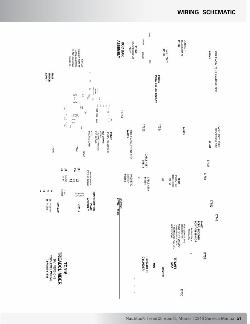
CABLE ASSY, T9 HR,PRO
CESSOR SIDE
#41442
TC916TREADCLIM
BER120V VERSIO
NSTO
P-LEVEL WIRING
T. BROW
N 6/15/05
KEYBOARD
CSAFE #1 PORT
(TOP ENTRY)
CSAFE #2 PORT
T.C. TREADLE POSITION SENSOR
SOFTW
ARE PRO
GRAM
MING
PORT
(TOP ENTRY)
T.C. PISTON CONTROL
DISPLAY(RIBBO
N CABLE TO
DISPLAY BOARD)
T.C. MO
TOR CO
NTROL
BOARD INTERFACE
(SIDE ENTRY)
ERGO
KEYS
REMO
TECHR/W
HR
MAG
NET
CABLE ASSY#41194
J16
J1
MAG
NETICSW
ITCH#40854
40824PCBA, P51
PROCESSO
RTC/TM
CABLE ASSY#41173
CABLE ASSY, FRONT RO
C#41193
CONFIG
URATION
PLATEASSEM
BLY
J3 J1
J2
LINEFILTER CIRCUIT
BREAKER
P2P3
TRANSFORM
ER(PART O
F #27962)
CONFIG
PCBA
P1P4
#27122Installs in place of
choke assembly
on Non-Europeantreadm
ills.
35774-001 or35774-002
#2731917744
CABLE ASSY, T9 HR, HANDRAIL SIDE
#41443
#41175
#40865PCBA, C52 LCD DISPLAY
CABLE ASSY#41169
GREY
GREEN
RED
GREEN
#41008TO
UCH SENSOR
ASSY
CONTACT/
TELEMETRY HR
#41180
ROC BAR
ASSEMBLY
+
HYDRAULICCYLINDER
++
MAX
MIN CENTER
TRAVEL
+++
#40837PCBA, ENCO
DERPO
SITION SENSO
R
#40825 ROTARY ENCO
DER 256 Q
UAD COUNT/REV
> 300 MILLIO
N CYCLE LIFEINDEX SENSO
R
INDEX (ZERO-PO
INT)LED INDICATO
R
DEPENDENCYM
ECHANISM
17746 17747
17748
17749
17750
17751
17752
17753
17754
17754
17755
TP9+16V
P11
P15
U7U8U9
U10
U11P5
P6THERM
ALSW
ITCHES
P7P8
P9
P20P17
P18
P1
P3
P14
P19
21109
1 10
9 8 7 4 3 14 3 2 1
2 1
P10
P12
P23
GRADESENSOR
RED
BLK
WHT
#41387PCBA, AC DRIVE III
DS1DS3
DS4 DS2
DS5
DS6
NOT SHO
WN:
#27965THERM
AL TRANSFERPAD (SILPAD)
#27571PAD, VSD CLAM
P
MAIN
MO
TOR
#27487
F1F2F4 F3
32533-001
KEYPANEL:#17716 TC916
WIrInG SchematIc

��
WIrInG SchematIc

��Nautilus® TreadClimber®, Model TC916 Service Manual
WIrInG SchematIc: 110 vac DomeStIc
2700
0
INST
ALLS
IN P
LAC
E O
F C
HO
KE A
SSY
ON
NO
N-E
UR
OPE
AN E
QU
IPM
ENT
1.PO
WER
CAB
LE L
ENG
TH 1
2FT.
2.SA
ME
TWO
PLA
CES
.3.
POW
ER C
OR
D IS
CO
UN
TRY
SPEC
IFIC
ON
INTE
RN
ATIO
NAL
MO
DEL
4.
MO
DEL
ASS
Y, T
REA
DC
LIM
BER
T9
0020
0-00
1
BRN
BLU
BRN
BLU
YEL
YEL
WH
T
BLK
RED
1
2
SOFT
WAR
EPR
OG
RAM
MIN
G P
OR
T
C'S
AFE
#1 P
OR
TC
'SAF
E #2
PO
RT
J1
J
15
J2
J14
J16
J3
J7
J9 J17
J11
J10
CO
NSO
LE A
SSY
TC9
1767
0
4119
341
443
C3 C1
C2
JUM
PER
2712
2
P1
1778
5N
EMA
5-20
P
PCB
P1 P4 J3 J1 (N
O C
ON
NEC
TIO
N)
P14
P11
P15
P20
P5 P6 P7 P8 P9
P10
P12
PBC
A AC
DR
IVE
1768
8VS
D A
SSY
T9M
AIN
MO
TOR
2748
7
UPR
IGH
T AS
SY T
C9
1762
6
ENC
OD
ER A
SSY
1754
5H
YDR
AULI
C C
YLIN
DER
ASSY
178
10(C
2)(C
1)
(C2)
(C1)
(C3)
CO
NSO
LE, P
CBA
, P51
4082
4PR
OC
ESSO
R T
C/T
M
(C3)
4117
3
4144
2
4117
5
ERG
O K
EYS
4144
9
CTH
R41
180
PCBA
, C52
LC
DD
ISPL
AY 4
0865
4119
4
MAG
NET
4115
4
MAG
NET
IC S
WIT
CH
ASSY
408
54
KEYP
ANEL
TC
917
716
OVE
RLA
Y17
739
1782
6
1777
8
1749
8
CO
NFI
GU
RAT
ION
PLAT
E AS
SY12
0V A
C 1
7719
1778
6
1782
4 3
3
1782
4
TRAN
SFO
RM
ER27
964
7 12

��
WIrInG SchematIc: 230 vac DomeStIc
1782
4 3
3
1782
4
1778
6C
ON
FIG
UR
ATI
ON
PLA
TE A
SS
Y23
0V A
C 1
7823
CH
OK
E41
404
17
85917
778
1782
6
OV
ER
LAY
1773
9
KE
YP
AN
EL
TC9
1771
6
MA
GN
ETI
C S
WIT
CH
AS
SY
408
54M
AG
NE
T41
154
4119
4
PC
BA
, C52
LC
DD
ISP
LAY
408
65
CTH
R41
180
ER
GO
KE
YS
4144
9
4117
5
4144
2
4117
3
(C3)
CO
NS
OLE
, PC
BA
, P51
4082
4P
RO
CE
SS
OR
TC
/TM
(C3)
(C1)
(C2)
(C1)
(C2)
HY
DR
AU
LIC
CY
LIN
DE
RA
SS
Y 1
7810
EN
CO
DE
R A
SS
Y17
545
UP
RIG
HT
AS
SY
TC
9 17
626
MA
IN M
OTO
R27
487
PB
CA
AC
DR
IVE
1768
8V
SD
AS
SY
T9
P5
P6
P7
P8
P9
P
10
P
12
P14
P19
P20
P1
P4
J3 J1 (N
O C
ON
NE
CTI
ON
)
PC
B
1759
0N
EM
A6-
15 P
P1
C2
C1
C3
4144
341
193
CO
NS
OLE
AS
SY
TC
9 17
670
J9 J17
J11
J10
J3
J7
J14
J16
J1
J
15
J2
C'S
AFE
#2
PO
RT
C'S
AFE
#1
PO
RT
SO
FTW
AR
EP
RO
GR
AM
MIN
G P
OR
T
2
YE
L
YE
L
WH
T
BLK
RE
D
BR
N
BLU
MO
DE
L A
SS
Y, T
RE
AD
CLI
MB
ER
T9
0020
0-00
2
27
000
TRA
NS
FOR
ME
R27
964
7 12

��Nautilus® TreadClimber®, Model TC916 Service Manual
WIrInG SchematIc: 230 vac InternatIonal
1782
4 3
3
1782
4
1778
6C
ON
FIG
UR
ATI
ON
PLA
TE A
SS
Y23
0V A
C 1
7823
CH
OK
E41
404
17
85917
778
1782
6
OV
ER
LAY
1773
9
KE
YP
AN
EL
TC9
1771
6
MA
GN
ETI
C S
WIT
CH
AS
SY
408
54M
AG
NE
T41
154
4119
4
PC
BA
, C52
LC
DD
ISP
LAY
408
65
CTH
R41
180
ER
GO
KE
YS
4144
9
4117
5
4144
2
4117
3
(C3)
CO
NS
OLE
, PC
BA
, P51
4082
4P
RO
CE
SS
OR
TC
/TM
(C3)
(C1)
(C2)
(C1)
(C2)
HY
DR
AU
LIC
CY
LIN
DE
RA
SS
Y 1
7810
EN
CO
DE
R A
SS
Y17
545
UP
RIG
HT
AS
SY
TC
9 17
626
MA
IN M
OTO
R27
487
PB
CA
AC
DR
IVE
1768
8V
SD
AS
SY
T9
P5
P6
P7
P8
P9
P
10
P
12
P14
P19
P20
P1
P4
J3 J1 (N
O C
ON
NE
CTI
ON
)
PC
B
P1
C2
C1
C3
4144
341
193
CO
NS
OLE
AS
SY
TC
9 17
837
(176
70)
J9 J17
J11
J10
J3
J7
J14
J16
J1
J
15
J2
C'S
AFE
#2
PO
RT
C'S
AFE
#1
PO
RT
SO
FTW
AR
EP
RO
GR
AM
MIN
G P
OR
T
2
YE
L
YE
L
WH
T
BLK
RE
D
BR
N
BLU
MO
DE
L A
SS
Y, T
RE
AD
CLI
MB
ER
T9
0020
0-00
3
27
000
4
TRA
NS
FOR
ME
R27
964
7 12
4139
9 5
TV TV IN
2X 1
7787
1778
7
1784
4
1784
5
1784
6

�6
WIrInG SchematIc: 110 vac DomeStIc WIth tv
127TR
AN
SFO
RM
ER
2796
4
1782
4 3
3
1782
4
1778
6C
ON
FIG
UR
ATI
ON
PLA
TE A
SS
Y12
0V A
C 1
7719
1749
81777
8
1782
6
OV
ER
LAY
1773
9
KE
YP
AN
EL
TC9
1771
6
MA
GN
ETI
C S
WIT
CH
AS
SY
408
54M
AG
NE
T41
154
4119
4
PC
BA
, C52
LC
DD
ISP
LAY
408
65
CTH
R41
180
ER
GO
KE
YS
4144
9
4117
5
4144
2
4117
3
(C3)
CO
NS
OLE
, PC
BA
, P51
4082
4P
RO
CE
SS
OR
TC
/TM
(C3)
(C1)
(C2)
(C1)
(C2)
HY
DR
AU
LIC
CY
LIN
DE
RA
SS
Y 1
7810
EN
CO
DE
R A
SS
Y17
545
UP
RIG
HT
AS
SY
TC
9 17
626
MA
IN M
OTO
R27
487
PB
CA
AC
DR
IVE
1768
8V
SD
AS
SY
T9
P5
P6
P7
P8
P9
P
10
P
12
P14
P11
P15
P20
P1
P4
J3 J1 (N
O C
ON
NE
CTI
ON
)
PC
B
1778
5N
EM
A5-
20 P
P1
JUM
PE
R27
122
C2
C1
C3
4144
341
193
CO
NS
OLE
AS
SY
TC
9 17
835
(176
70)
J9 J17
J11
J10
J3
J7
J14
J16
J1
J
15
J2
C'S
AFE
#2
PO
RT
C'S
AFE
#1
PO
RT
SO
FTW
AR
EP
RO
GR
AM
MIN
G P
OR
T
2
1
YE
L
YE
L
WH
T
BLK
RE
D
BR
N
BLU
BR
N
BLU
MO
DE
L A
SS
Y, T
RE
AD
CLI
MB
ER
T9
0020
0-00
4
2700
0
TV IN
TV
1784
6
1778
7
2X 1
7787
1784
5
1784
4

��Nautilus® TreadClimber®, Model TC916 Service Manual
WIrInG SchematIc: 230 vac DomeStIc WIth tv
127TR
AN
SFO
RM
ER
2796
4
2700
0
MO
DE
L A
SS
Y, T
RE
AD
CLI
MB
ER
T9
0020
0-00
5
BR
N
BLU
YE
L
YE
L
WH
T
BLK
RE
D
2
SO
FTW
AR
EP
RO
GR
AM
MIN
G P
OR
T
C'S
AFE
#1
PO
RT
C'S
AFE
#2
PO
RT
J1
J
15
J2
J14
J16
J3
J7
J9 J17
J11
J10
CO
NS
OLE
AS
SY
TC
9 17
835
(176
70)
4119
341
443
C3 C1
C2
P1
1759
0N
EM
A6-
15P
PC
BP
1
P4
J3 J1 (N
O C
ON
NE
CTI
ON
)
P14
P19
P20
P5
P6
P7
P8
P9
P
10
P
12
PB
CA
AC
DR
IVE
1768
8V
SD
AS
SY
T9M
AIN
MO
TOR
2748
7
UP
RIG
HT
AS
SY
TC
9 17
626
EN
CO
DE
R A
SS
Y17
545
HY
DR
AU
LIC
CY
LIN
DE
RA
SS
Y 1
7810
(C2)
(C1)
(C2)
(C1)
(C3)
CO
NS
OLE
, PC
BA
, P51
4082
4P
RO
CE
SS
OR
TC
/TM
(C3)
4117
3
4144
2
4117
5
ER
GO
KE
YS
4144
9
CTH
R41
180
PC
BA
, C52
LC
DD
ISP
LAY
408
65
4119
4
MA
GN
ET
4115
4
MA
GN
ETI
C S
WIT
CH
AS
SY
408
54
KE
YP
AN
EL
TC9
1771
6
OV
ER
LAY
1773
917
826
1777
8
1785
9
C
HO
KE
4140
4
CO
NFI
GU
RA
TIO
NP
LATE
AS
SY
2300
V A
C 1
7823
1778
6
1782
4 3
3
1782
4
1784
617
787
2X 1
7787
1784
5
1784
4
TV IN
TV

��
officeS iN the uNiteD StateS:
E-mail: [email protected]
• NAUTILUS INNOVATION CENTERNautilus, Inc.1886 Prairie WayLouisville, Colorado, USA 80027Vancouver, Washington, USA 98683Phone: 800-NAUTILUS (800-628-8458)Email: [email protected]: 800-898-9410
• TECHNICAL/CUSTOMER SERVICENautilus, Inc.World Headquarters16400 SE Nautilus DriveVancouver, Washington, USA 98683Phone: 800-NAUTILUS (800-628-8458)Email: [email protected]: 877-686-6466
• CORPORATE HEADQUARTERSNautilus, Inc.World Headquarters16400 SE Nautilus DriveVancouver, Washington, USA 98683Phone: 800-NAUTILUS (800-628-8458)
If you need assistance, please have both the serial number of your machine and the date of purchase available when you contact the appropriate Nautilus office listed below.
iNteRNatioNal:
For technical assistance and a list of distributors in your area, please call or fax one of the following numbers.
• INTERNATIONAL CUSTOMER SERVICENautilus International S.A.Rue Jean Prouvé 61762 Givisiez / SwitzerlandTel: + 41-26-460-77-77Fax: + 41-26-460-77-70 Email: [email protected]
buSiNeSS officeS:
• SWITzERLAND OFFICENautilus Switzerland S.A.Tel: + 41-26-460-77-66Fax: + 41-26-460-77-60
• GERMANY and AUSTRIA OFFICE Nautilus GmbH Tel: +49-2204-610-27Fax: +49-2204-628-90
• ITALY OFFICE Nautilus Italy s.r.l.Tel: +39-031-51-10-86Fax: +39-031-34-24-97
• UNITED KINGDOM OFFICENautilus UK Ltd.Tel: +44-1908-267-345Fax: +44-1908-267-346
• CHINA OFFICENautilus Representative OfficeTel: +86-21-523-707-00Fax: +86-21-523-707-09
Important contact numberS

�9Nautilus® TreadClimber®, Model TC916 Service Manual
paGe IntentIonally left BlanK
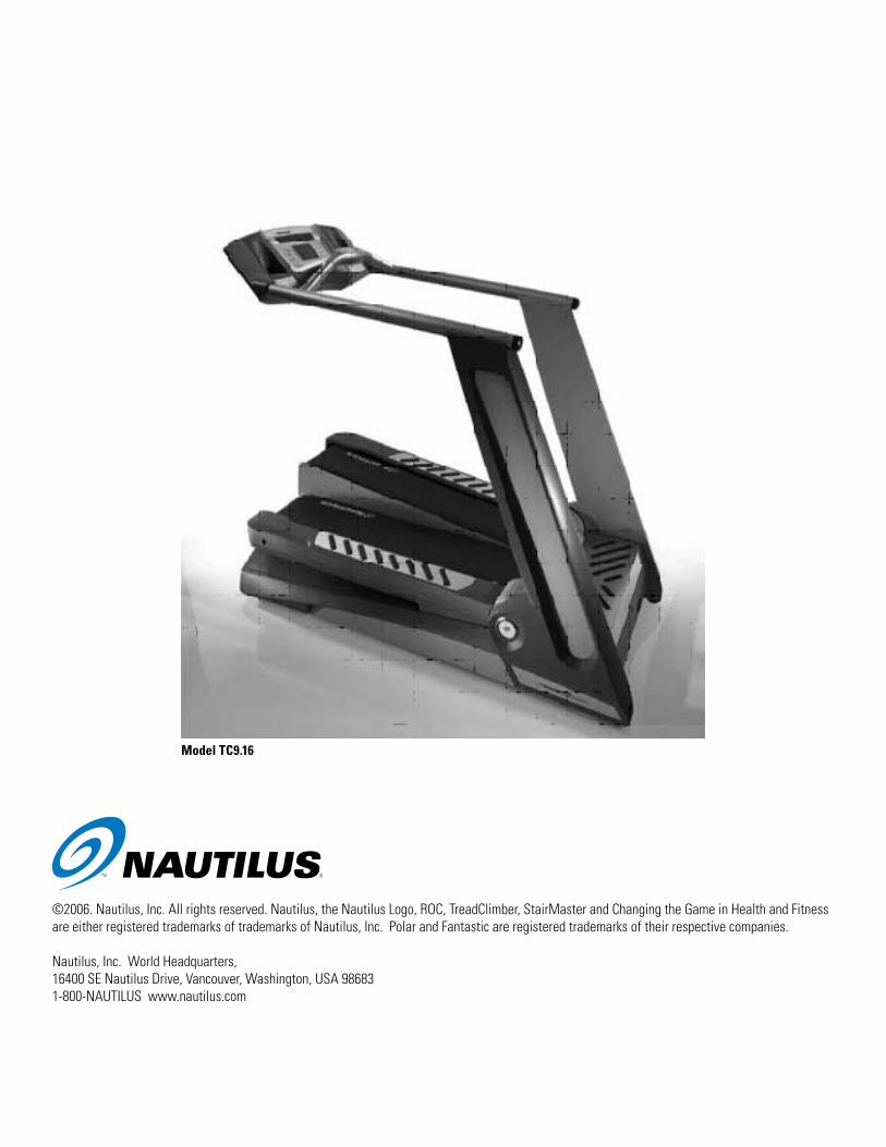
©2006. Nautilus, Inc. All rights reserved. Nautilus, the Nautilus Logo, ROC, TreadClimber, StairMaster and Changing the Game in Health and Fitness are either registered trademarks of trademarks of Nautilus, Inc. Polar and Fantastic are registered trademarks of their respective companies.
Nautilus, Inc. World Headquarters, 16400 SE Nautilus Drive, Vancouver, Washington, USA 986831-800-NAUTILUS www.nautilus.com
Model tc9.16