service manual vacuum-belt applicator 5426c
TRANSCRIPT

MF
Made in Germany
Service Manual
5426CVacuum-Belt Applicator
2 2
Family TypeVacuum-Belt Applicator 5426C
Edition: 04/2018 - Part No. 9003096
CopyrightThis documentation as well as translation hereof are property of cab Produkttechnik GmbH & Co. KG. The replication, conversion, duplication or divulgement of the whole manual or parts of it for other intentions than its original intended purpose demand the previous written authorization by cab.
EditorRegarding questions or comments please contact cab Produkttechnik GmbH & Co. KG.
TopicalityDue to the constant further development of our products discrepancies between documentation and product can occur.Please check www.cab.de for the latest update. Terms and conditionsDeliveries and performances are effected under the General conditions of sale of cab.
Service Manual for the following Products
Germanycab Produkttechnik GmbH & Co KGKarlsruhePhone +49 721 6626 0www.cab.de
USAcab Technology, Inc.Chelmsford, MAPhone +1 978 250 8321www.cab.de/us
Taiwancab Technology Co., Ltd.TaipeiPhone +886 (02) 8227 3966www.cab.de/tw
Chinacab (Shanghai) Trading Co., Ltd.Guangzhou Phone +86 (020) 2831 7358www.cab.de/cn
Francecab Technologies S.à.r.l.NiedermodernPhone +33 388 722501www.cab.de/fr
Mexicocab Technology, Inc.JuárezPhone +52 656 682 4301www.cab.de/es
Chinacab (Shanghai) Trading Co., Ltd.ShanghaiPhone +86 (021) 6236 3161www.cab.de/cn
South Africacab Technology (Pty) Ltd.RandburgPhone +27 11 886 3580www.cab.de/za

2 31 Introduction ............................................................................................................................................ 41.1 Instructions ............................................................................................................................................... 41.2 Intended Use ............................................................................................................................................ 41.3 Safety Instruction ..................................................................................................................................... 41.4 Safety Markings ....................................................................................................................................... 51.5 Environment ............................................................................................................................................. 5
2 Product Description ............................................................................................................................... 62.1 Important Features ................................................................................................................................... 62.2 Technical Data .......................................................................................................................................... 62.3 Device Overview ...................................................................................................................................... 72.4 Contents of Delivery ................................................................................................................................. 8
3 Operation ................................................................................................................................................ 93.1 Standard Operation .................................................................................................................................. 93.2 Cleaning ................................................................................................................................................... 93.3 Power Supply of the Device ................................................................................................................... 103.4 Pivoting the Applicator .............................................................................................................................11
4 Error Messages .................................................................................................................................... 124.1 Error Messages of the Printer ................................................................................................................ 124.2 Error Messages of the Applicator ........................................................................................................... 12
5 Installation ............................................................................................................................................ 135.1 Factory Default Settings ......................................................................................................................... 135.2 Tools ....................................................................................................................................................... 135.3 Mounting and Dismounting the Applicator .............................................................................................. 145.4 External Start Sensor ............................................................................................................................. 15
6 Adjustments ......................................................................................................................................... 166.1 Adjusting the Angle to the Printer ........................................................................................................... 166.2 SettingsintheConfigurationofthePrinter ............................................................................................ 176.3 Signals ................................................................................................................................................... 17
7 Configuration ........................................................................................................................................ 187.1 Quick Mode for Setting the Delay Times ................................................................................................ 187.2 ConfigurationParametersoftheApplicator ........................................................................................... 187.3 Setting the Peel Position ........................................................................................................................ 197.4 Activating the Peel-off Mode .................................................................................................................. 19
8 Test Operations .................................................................................................................................... 208.1 Test Mode without a Print Job ................................................................................................................ 208.2 Test Mode with Print Job ........................................................................................................................ 20
9 Replacing Components ....................................................................................................................... 219.1 Exchanging the Pinch Roller .................................................................................................................. 21
10 Spare Parts ........................................................................................................................................... 2210.1 Control Unit ............................................................................................................................................ 2210.2 Vacuum-belt Section 1 ........................................................................................................................... 2310.3 Vacuum-belt Section 2 ........................................................................................................................... 24
11 Block Diagram ...................................................................................................................................... 25
12 Index ...................................................................................................................................................... 26
Table of Contents

4 41 Introduction1.1 Instructions
Important information and instructions in this documentation are designated as follows:
Danger!Draws attention to an exceptionally great, imminent danger to your health or life due to hazardous voltages.
!Danger!Draws attention to a danger with high risk which, if not avoided, may result in death or serious injury.
!Warning!Draws attention to a danger with medium risk which, if not avoided, may result in death or serious injury.
!Caution!Draws attention to a danger with low risk which, if not avoided, may result in minor or moderate injury.
! Attention!Draws attention to potential risks of property damage or loss of quality.
i Note!Advice to make the work routine easier or on important steps to be carried out.
Environment!Gives you tips on protecting the environment.
Handling instruction
Reference to section, position, illustration number or document.
Option(accessories,peripheralequipment,specialfittings).
Time Information in the display.
1.2 Intended Use• The device is manufactured in accordance with the current technological status and the recognized safety rules.
However, danger to the life and limb of the user or third parties and/or damage to the device and other tangible assets can arise during use.
• The device may only be used for its intended purpose and if it is in perfect working order, and it must be used with regard to safety and dangers as stated in the operating manual.
• The device applicator mounted on a cab printer of the Hermes+ series is intended exclusively for applying suitable materials that have been approved by the manufacturer. Any other use or use going beyond this shall be regarded as improper use. The manufacturer/supplier shall not be liable for damage resulting from unauthorized use; the user shall bear the risk alone.
• Usage for the intended purpose also includes complying with the operating manual, including the manufacturer‘s maintenancerecommendationsandspecifications.
i Note! The complete documentation can currently be found in the Internet.
1.3 Safety Instruction
• Before mounting the delivered components disconnect the printer from the power supply and close the shutoff valve at the applicator.
• Only connect the device to other devices which have a protective low voltage.• Switch off all affected devices (computer, printer, accessories) before connecting or disconnecting.• In operation, moving parts are easily accessible.
This applies especially for the zone of belts and fans. During operation do not reach into that zone and keep long hair, loose clothes, and jewelry distant.
• During operation do not reach into that zone and keep long hair, loose clothes, and jewelry distant. • The device may only be used in a dry environment, do not expose it to moisture (sprays of water, mists, etc.).• Do not use the device in an explosive atmosphere.

4 51 Introduction• Do not use the device close to high-voltage power lines.• Perform only those actions described in this operating manual.
Work going beyond this may only be performed by trained personnel or service technicians.• Unauthorized interference with electronic modules or their software can cause malfunctions.• Otherunauthorizedworkonormodificationstothedevicecanalsoendangeroperationalsafety.• Alwayshaveserviceworkdoneinaqualifiedworkshop,wherethepersonnelhavethetechnicalknowledgeand
tools required to do the necessary work.• There are various warning stickers on the device. They draw your attention to dangers. Warning stickers must
therefore not be removed, as then you and other people cannot be aware of dangers and may be injured.
1.4 Safety Markings
32
1
1: Warning danger of electrocution.
2: Warning of contusions and/or crushingofhandsandfingerswhen mounting or dismounting the applicator!
3: Beware of rotating parts. Potential bodily harm particularly to hands andfingers.
2
Fig. 1 Safety Markings
! Attention!Never remove or cover safety markings! Replace it in case of damage!
1.5 Environment
Obsolete devices contain valuable recyclable materials that should be sent for recycling. Send to suitable collection points, separately from residual waste.
The modular construction of the print module enables it to be easily disassembled into its component parts. Send the parts for recycling.
6 62 Product Description2.1 Important Features
• For operation in a system the I/O interface of the printer can be used.
2.2 Technical Data
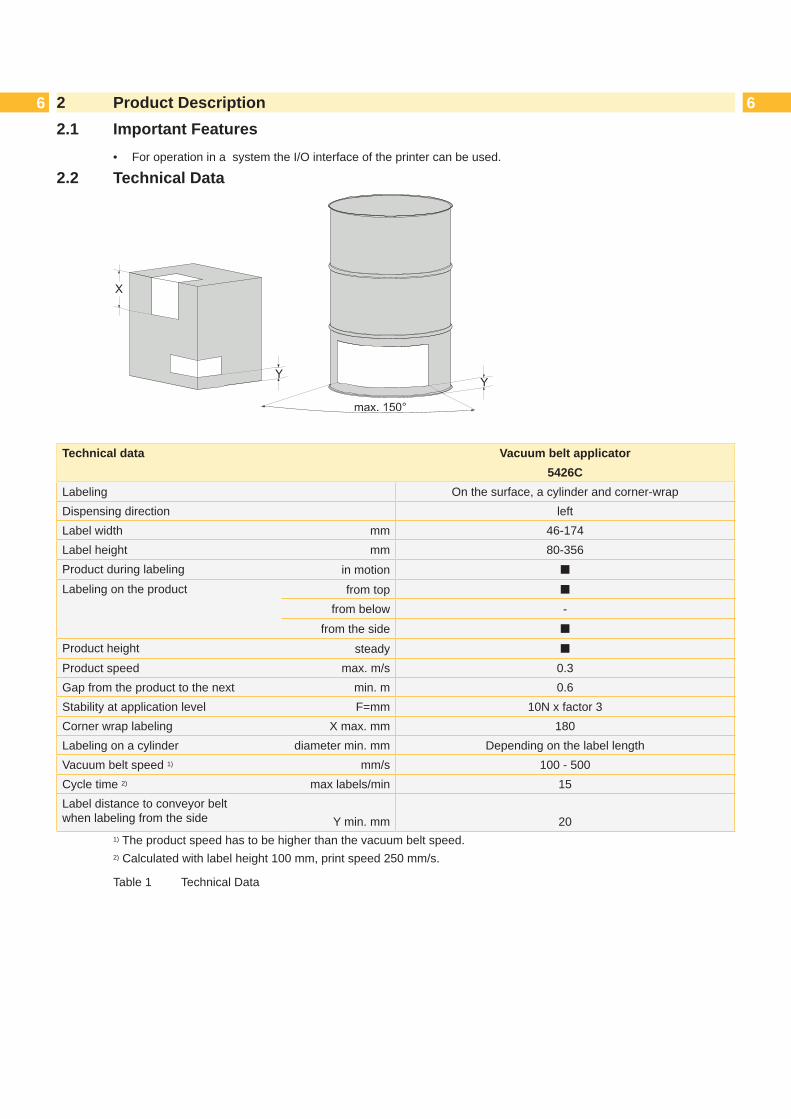
Technical data Vacuum belt applicator5426C
Labeling On the surface, a cylinder and corner-wrapDispensing direction leftLabel width mm 46-174Label height mm 80-356Product during labeling in motion ¢
Labeling on the product from top ¢
from below -from the side ¢
Product height steady ¢
Product speed max. m/s 0.3Gap from the product to the next min. m 0.6Stability at application level F=mm 10N x factor 3Corner wrap labeling X max. mm 180Labeling on a cylinder diameter min. mm Depending on the label lengthVacuum belt speed 1) mm/s 100 - 500Cycle time 2) max labels/min 15Label distance to conveyor belt when labeling from the side Y min. mm 20
1) The product speed has to be higher than the vacuum belt speed.2) Calculated with label height 100 mm, print speed 250 mm/s.
Table 1 Technical Data

6 72.3 Device Overview
4
23
1
5
6
7
8
10
11
12
9
13
4
11
14
1 Power supply cable of the printer2 3-pole connector for sensor start3 Power switch applicator4 SUB-D 9 connector to the printer5 Circuit board applicator control6 Belt driven motor7 Vacuum belt unit and ventilators8 Sensor9 Power supply with cover10 Belt with motor shaft belt11 Locking bold12 Pinch roller13 Gas pressure spring for the vacuum unit14 Shock-absorber
Fig. 2 Overview
2 Product Description

8 82.4 Contents of Delivery
2
1
2
3
Fig. 3 Contents of delivery
- Mounted applicator (1) - Screws for mounting the applicator to the printer (2) - 4 x self-adhering cable guides - Documentation
i Note! Please keep the original packaging in case the applicator needs to be transported or returned.
! Attention!The device and printing materials will be damaged by moisture and liquid.
Only set up the label printer with applicator in dry locations protected from moisture.
2 Product Description

8 93 Operation3.1 Standard Operation
Check all external connections. Load the material. "Operator's Manual" Switch on the printer. Press the feed key of the printer.
A synchronization feed is initiated. The processed labels need to be removed manually. After a few seconds the printer carries out a short backfeed to position the front edge of the next label at the printing line.
i Note!This synchronization also has to be carried out when the print job is interrupted with the cancel key.Synchronizing is not necessary if the print head was not lifted between print jobs. This also applies if the printer was powered off in between print jobs.
Start a print job. Start the labeling process via PLC interface.
Error messages that occur during the labeling process are shown in the display of the printer.
3.2 Cleaning
! Attention!Never use solvent and abrasive.
1
2
3
4
Dismount the applicator in order to reach all areas. „5.3 Mounting and Dismounting the Applicator“
For cleaning the outer surfaces (1) and transport belts a multipurpose cleaner is sufficient.
Clean the fan area (2) with a soft brush or a vacuum cleaner.
Useglasscleanertocleanthereflexsensor (3).
Clean the pinch roller (4) with a special pinch roller cleaner or a multi purpose cleaner.
Remount the applicator
Fig. 4 Cleaning

10 103 Operation3.3 Power Supply of the Device
1 3 542
Fig. 5 Power supply of the printer and the applicator
! Attention!Whenthepowercableisconnectedtheentirecurrentflowsthroughthepowersupplyoftheprinter.Thepower switch of the applicator only affects the powers supply of the applicator. 1. Plug the power cable (2), as part of the contents of delivery, into the plug point of the applicator. 2. Disconnect the plug (4) of cable (3) of the applicator and plug it into the plug point of the printer. 3. Switch on the applicator via the switch (1). 4. Power up the printer.
i Note! If only the printer is powered and not the applicator, the error message: Compressed air error will be displayed.5. To better organize the cables use the self adhering cable clamps (1). These clamps may be freely placed to best
suit the needed support for the cables.

10 113.4 Pivoting the Applicator
1
432 5
Fig. 6 Pivoting the applicator
! Attention!Dangerofinjurytohandsandfingersbytheapplicator!When releasing the snap lock keeping the applicator in place, it will drop due to its own weight. 1. To dismount the applicator (1), for cleaning or inserting material, pull the locking bolts (4) outward.2. With pulled out locking bots (4) lift the applicator (1) until the bolts can snap into the provided holes (5) of the
mounting plate (3). 3. To remount the applicator pull the locking bolts (4) outward again and push the applicator toward the printer until
the bolts (4) can securely lock into the provided holes (2) on the mounting plate (3).
3 Operation

12 124 Error Messages4.1 Error Messages of the Printer
For detailed information about printer errors (e.g. 'Paper out', 'Ribbon out', etc.) Operator's manual of the printerError treatment:
Clear the error results. Press the feed key to synchronize the label feed and remove the peeled labels manually. Press the pause key to quit the error state.
After error correction, the label causing the error will be reprinted.
4.2 Error Messages of the ApplicatorThe following table contains an overview of error messages and their possible causes. It also suggests methods to resolve the problem:
Error Message Possible Cause
Vac. plate empty Label is removed from the waiting position on the pressure roll before the signal START is coming in.
Upper position Labelhasnotreachedtheareaofthereflexsensorafter5secorwasnotdetected.
Table 2 Error messages of the applicator
Error treatment: Clear the error results Press the pause key to quit the error state.
i Note!In fault check adjustments and settings with help of the Service Manual.
After error correction, the print of the label causing the error cannot be repeated without re-start the print job. Except at the error "Vac. plate empty". In this case, the last label will be printed again after the error state has been quit with the pause key and by then pressing the Enter button .
Intheapplicationmode"Apply/Print"sendthesignal"Printfirstlabel"orpressthebutton to send a printed labeltothereflexsensorpositionontheapplicator.

12 135 Installation5.1 Factory Default Settings
i Note! Theapplicatorsaresettodefaultconfigurationsbyfactorystandards.Thesevaluesguaranteeaseamlessoperation within the parameters.
i Note!If the customer requires a custom setup the parameters will be pre installed. These values may deviate from the factory default parameters. The values are listed in the setup protocol and delivered with the printer applicator system.
The default factory values are: - Connected to a cab Hermes+ printer, vertical - Default material used for the setup: cab part No.: 5556472 54x35.5
5.2 Tools
• Crosstip screwdriver (Phillips)
2 to adjust the sensor
• Hexagon key L-wrench 2.5 for matched norm parts (in delivery state of the applicator)
3 5
to set the angle of the applicatorto adjust the pressure roller
• Flat-round noise straight
angled
Table 3 Tools

14 146 Installation5.3 Mounting and Dismounting the Applicator
9
2
10
3 4 61
7
5
8
Fig. 7 Mounting and dismounting the applicator
! Attention!Initiation,adjustmentsandchangingofpartsistobeperformedbyqualifiedservicepersonnelonly. Service Manual Applicator.
! Attention! Disconnect the printer from the power supply before mounting the applicator! Ensure the printer is standing securely in a stable position!
To clean the applicator and printer it is sometimes necessary to pivot away or even dismount the applicator entirely from the printer. Do not adjust the setting screws, throttle valves or other alignment elements as this will enable use of the applicator directly after cleaning.Dismounting the Applicator1. Pull the power cable (7) out of the printer and power cable (5) out of the applicator.2. Undo the screws (9) from the retainer (10).3. Holdtheapplicatorfirmlyandloosenscrews(6).4. Move the applicator forward and pull the SUB-D connector (3) out of the socket (1) of the printer.5. Detach the applicator by lifting it away.Remounting the Applicator6. Lift the applicator onto the printer and connect the SUB-D connector (3) to the socket (1).7. Place the applicator onto the retainer (8). Push the applicator onto the printer so that the upper holes (4) of the
hinge plate are congruent to the holes (2) of the printer.8. Insert and fasten screws (6).9. Insert and fasten screws (9).10. Connect power cables (5 and 7).

14 156 Installation5.4 External Start Sensor
The start signal to apply the label can originate from an external sensor connected to the 3 pole connector (1) connected directly to the applicator.
1
Fig. 8 Start signal connector on the applicator
Fig. 9 Examples of connections of start sensors
Thestartoftheprintingjob-printfirstlabelisstillinitiatedovertheI/Ointerfaceoftheprinter.Circuitryandprogramming of the connections is to be set as illustrated „6.3 Signals“

16 166 Adjustments
i Note!The position of the applicator to the printer is predetermined by the factory and should not be altered to guarantee a reliable label take-over. Only change the angle of the applicator and the pressure of the pinch roller.
6.1 Adjusting the Angle to the Printer
1
max 20°
Fig. 10 Angle of the applicator to the printer
!Warning!If you loosen screw (1) the device will drop onto its own weight! Potential risk of injury!
Loosen screw (1) to set the angle, and depth, of the applicator to the printer. Set the angle to the product (4) and fasten the screw (1). „7.2SettingsintheConfigurationofthePrinter“

16 177 Adjustments6.2 SettingsintheConfigurationofthePrinter
32
1
4
Fig. 11 Labeltransport/reflexsensor
Waiting position of the label
The operation mode "Blow" must be selected in the setup. Only once this is selected is it possible to change the parameter "Blow time".Afterdetectionofthelabel(1)bythereflexsensor(2)itwillbetransportedfurtherforasettimetoreachthepinchroller (4). To change this value use the parameter:
> Blow time
A higher value causes a longer transport distance. 200 ms equates to approximately 10 mm. „7.2ConfigurationParametersoftheApplicator“
Overrun of the label
Ifthelabel(1)hasleftthesensorarea(3)itwillbetransportedforadefinedtimetoapplythelabelviatheroller.Tochange this overrun time use the parameter:
> Support delay on
6.3 Signals• The signal DREE causes the label to be printed which is then transported to the waiting position.• The signal START will transport and apply the label to the product.
In the application mode "Apply - Print" the printing of the next label starts directly after application of the previous label. In the application mode "Print - Apply" the signal DREE must be sent for the print of each label.
Pin Signal Name Description Activation/active statuswithout applicator with applicator
1 DREE - printfirstlabelinmode "Apply-Print"
Switch on +24V between Pin 1 and Pin 25
13 START Print start signalPrecondition: The superior control hasconfirmedwiththeETEsignalthat the previous label has been taken from the peel-off position.
Start of printing and labeling +24V between Pin 13 and Pin 25
Table 4 A section of the interface description of the label printer Hermes+

18 187 Configuration7.1 Quick Mode for Setting the Delay Times
It is possible to set the transport speed of the label in four steps.By switching the parameter to Support del. off.Besidethestandardmethodfortheprinterconfigurationthereisaquickmodetoadjustthedelaytimesavailable.
i Note!The quick mode settings can be made during operation . The changes directly affect the current print job. 1. Press the menu key for at least 2 seconds.
Thefirstdelaytimeappearsonthedisplay.2. Adjust the delay time by pressing the ~ key and � key.3. To switch between the different delay times press the } key.4. To leave the quick setup mode press the | key.
The selected delay times are stored by the printer.
7.2 ConfigurationParameters of the ApplicatorTheconfigurationparametersoftheapplicatorcanbefoundinthemenuSetup > Machine param.
i Note! The speed of the belt and the label transport is set by the parameter Support del. off. The value is displayed in ms and not the actual value used mm/s.
i Note! It is necessary to set the values of the table precisely. Deviation from the listed values will cause the default value of 100 to be used.
Parameter Meaning Default> Support del.
offParameter to set the speed of the belts. Four steps are available.100 ms: 100 mm/s speed of the transport belt150 ms: 150 mm/s speed of the transport belt220 ms: 220 mm/s speed of the transport belt300 ms: 300 mm/s speed of the transport belt500 ms: 500 mm/s speed of the transport belt
100 ms
Table 5 Applicator parameters

18 197.3 Setting the Peel Position
To optimize the transfer of the labels from the printer to the applicator there are two different parameters available for adjusting the peel position.
! Attention! Firstadjusttheparameter"PeelPosition"intheprinterconfiguration. Then adjust the additional peel-off offset in the software.
It is very important to follow this procedure for a seamless start after loading material and dealing with the treatment of error.
Parameter"PeelPosition"intheprinterconfiguration
Check the basic setting in the printer setup. Perform labeling cycles by alternating between the feed key and the enter /pre-dispense key „8.1 Test Mode without a Print Job“
Adjust the "Peel Position" in such a way, that the blank labels are peeled-off the liner completely. „7.2Configu-ration Parameters of the Applicator“
Peel-off offset in the software
Check the setting in the software. Perform labeling cycles by repeatedly pressing the the pre-dispense key 8.3 Setting the Peel Position
Adjust the peel-off offset in such a way, that the printed labels are peeled off the liner completely. Programming manual or software documentation.
7.4 Activating the Peel-off Mode
i Note! For labeling operations activate the peel-off mode in the software.
For direct programming use the P command Programming manual.
8 Configuration

20 208.1 Test Mode without a Print Job
! Warning!During operation movable parts are easily accessible. Particularly the transportation belts and fans pose a threat!
Do not reach into these areas and keep things like long hair, loose clothes and jewelery away.
2
1
Fig. 12 Test mode via enter key
i Note! Pleaseusethetestmodetoadjusttheparameter"Peelposition"intheprinterconfiguration.
The whole labeling process can be simulated without the need of a print job or a connection to a computer by alter-nately pressing the feed (2) key and the Enter key (1):
Press the feed key (2). A blank label is fed. The vacuum from the fans as well as the supporting air (blow tube) are switched on. After detectionofthelabelbythereflexsensor,thesupportingairisswitchedoff.
Press the Enter key (1). The label will be moved to the labeling position.
8.2 Test Mode with Print Job
i Note! Please use that test mode to adjust the peel-off offset in the software.
The following method allows the testing of the labeling process with the real print data using the Enter key (1). Send a print job.
The test mode is executed in two half cycles: Press the Enter key (1).
Half cycle 1 A label is printed. The vacuum from the fans as well as the supporting air (blow tube) are switched on. After the label has been picked up by the applicator, the supporting air is switched off.
Press the Enter key (1) again. Half cycle 2 The label is moved to the labeling position.
Ifthelabelismanuallyremovedafterthefirsthalfcycle,thehalfcycle1willberepeatedwhenthepre-dispensekeyis pressed again.
8 Test Operations

20 219 Replacing Components9.1 Exchanging the Pinch Roller
1 2 3 4 15
Fig. 13 Exchanging the pinch roller
1. Loosen screws (1).2. Take out the pinch roller (2) with tubes (3) and the axle (4) out of the frame (5).3. Pull out the axle shaft (4). 4. Remove the tubes (3) from the pinch roller (2) and place them into the new pinch roller.5. Reassemble the pinch roller in the reverse order to disassembling it.

22 2210 Spare Parts10.1 Control Unit
Fig. 14 Control unit - spare parts
No. Part No. Description PU Serial No.from to
1 5902838.001 Screw DIN7984-M3x6 102 5948154.001 Cover 13 5900041.001 Distance Bolt M3x30 104 5918631.001 Power Supply 15 5905349.001 Switch 16 5918052.001 Power Plug 17 5902565.001 Screw DIN7984-M4x10 108 5903033.001 Washer DIN125-A4.3 109 5903011.001 Toothed Washer DIN6797-A4.3 10
10 5555001.001 Cable 111 5534732.001 Cable Grounding 112 5905605.001 Belt 91 MXL 037 113 5902571.001 Screw DIN7984-M4x6 1014 5972738.001 Bracket 115 5907443.001 Pneumatic Spring 1 1102715 5907531.001 Pneumatic Spring 1 1102816 5972456.001 Gear 29 117 5972605.001 Lever 1 1102717 5979252.001 Lever 1 11028
No. Part No. Description PU Serial No.from to
18 5970246.001 Sensor Adapter 119 5555004.001 Cable USB 120 5551244.001 PCB Applicator Control 121 5901575.001 Cable Clamp 1022 5906778.001 Locking Pin 123 5952587.001 Cable Motor 124 5946206.001 Stepper Motor 125 5972859.001 Locking Part 126 5972861.001 Hinges 127 5972862.001 Support 128 5972603.001 Retainer 1 1102728 5979253.001 Retainer 1 1102829 5902910.001 Screw DIN7984 M5x10 1030 5972699.001 Cover 131 5972953.001 Holder Shock Absorber 132 5907036.001 Shock Absorber 133 5902159.001 Screw DIN912-M5x12 10

22 2311 Spare Parts10.2 Vacuum-belt Section 1
Fig. 15 Vacuum-belt section 1 - spare parts
No. Part No. Description PU Serial No.from to
7 5902565.001 Screw DIN7984-M4x10 108 5903033.001 Washer DIN125-A4.3 10
13 5902571.001 Screw DIN7984-M4x6 1021 5901575.001 Cable Clamp 1029 5902910.001 Screw DIN7984 M5x10 1034 5902290.001 Screw DIN912-M5x35 1035 5909072.001 Friction Bearing d=22 1035 5972589.001 Bearing Journal 136 5972460.001 Adapter 137 5907407.001 Circular Belt 4,0x616-V 1038 5902015.001 Screw DIN7991-M4x35 1039 5972595.001 Motor Shaft 140 5904004.001 Pin DIN1481 3x16 1041 5972590.001 ProfileAxle 1
No. Part No. Description PU Serial No.from to
42 5902304.001 Screw DIN7991-M4x6 1043 5905271.001 Grommet 8x3 1044 5972593.001 ProfileAxle 145 5972586.001 Base Plate 146 5972173.001 Fan 147 5906299.001 Fan Grid 80x80mm 148 5902570.001 Nut DIN982-M4 1049 5551232.001 Distribution PCB Fan 150 5972899.001 Mounting Plate 151 5961638.001 Antistatic Brush 152 5952696.001 Cable 153 5972685.001 Cover 185 5972962.001 Support 1 11028
24 2411 Spare Parts10.3 Vacuum-belt Section 2
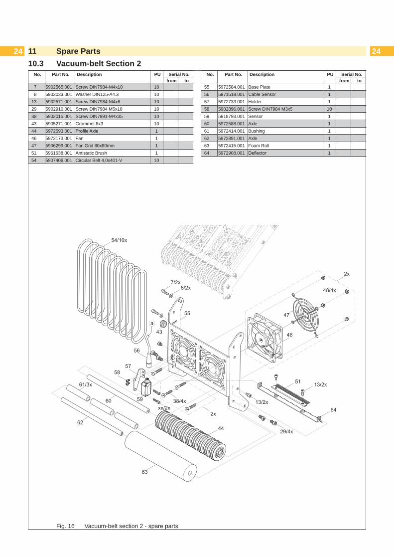
Fig. 16 Vacuum-belt section 2 - spare parts
No. Part No. Description PU Serial No.from to
7 5902565.001 Screw DIN7984-M4x10 108 5903033.001 Washer DIN125-A4.3 10
13 5902571.001 Screw DIN7984-M4x6 1029 5902910.001 Screw DIN7984 M5x10 1038 5902015.001 Screw DIN7991-M4x35 1043 5905271.001 Grommet 8x3 1044 5972593.001 ProfileAxle 146 5972173.001 Fan 147 5906299.001 Fan Grid 80x80mm 151 5961638.001 Antistatic Brush 154 5907406.001 Circular Belt 4,0x401-V 10
No. Part No. Description PU Serial No.from to
55 5972584.001 Base Plate 156 5971518.001 Cable Sensor 157 5972733.001 Holder 158 5902896.001 Screw DIN7984 M3x5 1059 5918793.001 Sensor 160 5972588.001 Axle 161 5972414.001 Bushing 162 5972891.001 Axle 163 5972415.001 Foam Roll 164 5972908.001 Deflector 1

24 2511 Block Diagram
19PCB applicator
control
CO
N 1
C
ON
2
CO
N 4
Fig. 17 Block diagram
EEPROM
C
ON
7
CO
N 8
C
ON
9
18 SUB-D 9
Connection to the printer
19/41 Label sensor
20/21 Motor belt driven
52Distribution PCB fan
C
ON
1
CO
N 2
C
ON
3
59 Fan
59 Fan
59 Fan
C
ON
4
CO
N 5
C
ON
6
CON 7
CON 8

26 2612 Index13 IndexB
Block diagram ...................................25
C
Cleaning .............................................9Configurationparameters .................18Contents of delivery ............................8Control unit .......................................22
D
Delay times .......................................18
E
Environment .......................................5Error messages of the applicator......12Error messages of the printer ...........12Exchanging the pinch roller ..............21External start sensor.........................15
F
Factory default settings ....................13
I
Important information..........................4Instructions .........................................4Intended use .......................................4
M
Mounting the applicator ....................14
O
Operation ............................................9Overrun of the label ..........................17
P
Parameter .........................................18Peel-off mode ...................................19Peel position .....................................19Pivoting the applicator ...................... 11Power supply ....................................10Print job ............................................20
Q
Quick mode - delay times .................18
S
Safety instruction ................................4Safety markings ..................................5Setting the peel position ...................19Signals ..............................................17Spare parts .......................................22Standard operation .............................9Start sensor ......................................15
T
Technical data.....................................6Test mode .........................................20Tools .................................................13
V
Vacuum-belt ......................................23