service oriented architectures, the dod architecture ... · service oriented architectures, the dod...
TRANSCRIPT
Service OrientedArchitectures, the DoDArchitecture Framework1.5, and ExecutableArchitecturesLee W. Wagenhals* and Alexander H. Levis
System Architectures Laboratory, Electrical and Computer Engineering Department, George Mason University, Fairfax,VA 22030-4444
SOAs, DoDAF 1.5, AND EXECUTABLE ARCHITECTURES
Received 31 March 2008; Revised 8 September 2008; Accepted 8 September 2008, after one or more revisionsPublished online in Wiley InterScience (www.interscience.wiley.com)DOI 10.1002/sys.20125
ABSTRACT
The Department of Defense (DoD) has defined a Net Centric Warfare concept to help lead
the way in the transformation of DoD capabilities in the information age. Service Oriented
Architectures (SOA) has been selected as an approach for achieving many of the goals of this
transformation. The DoD has created a major revision in its DoD Architecture Framework
(DoDAF) that enables the inclusion of SOA. This paper describes a process for creating a
DoDAF 1.5 compliant architecture that includes the description of the SOA aspects, a mapping
and a process for converting that architecture to an executable model, and the use of that
executable model in the evaluation of logical, behavioral, and performance aspects of the
architecture. The concepts are illustrated with a detailed Case Study. © 2008 Wiley Periodicals,
Inc. Syst Eng
Key words: modeling and simulation of collaboration; executable models of architectures;
unified modeling language; architectures and design of collaborative systems; human-ma-
chine collaborative interactions; collaboration technologies in industry and business
Regular Paper
*Author to whom all correspondence should be addressed (e-mail: [email protected]; [email protected]).
Contract grant sponsor: Office of Naval Research; Contract grant number: N00014-08-1-0319
Systems Engineering© 2008 Wiley Periodicals, Inc.
1
1. INTRODUCTION
The Department of Defense (DoD) Net Centric Warfare(NCW) concept is key to the transformation of DoDcapabilities in the information age. Developing bothoperational concepts and systems that support thoseconcepts based on ubiquitous information and datasharing across traditional boundaries is at the heart ofNCW and its enabler called Net Centric Operations(NCO). This implies a shift from platform orientationbased on tightly coupled or large-scale monolithic sys-tems to a spectrum of integration techniques that in-clude loosely coupled systems-of-systems. The DoDviews architectures as the mechanism for designingsolutions for this transformation, and the use of ServiceOriented Architectures (SOAs) has been selected as anapproach for achieving many of the goals of this trans-formation.
To support this transformation, DoD has issued amajor revision in its DoD Architecture Framework thatenables the inclusion of services-based architectures.The result of this transformation and DoDAF decisionsis that there is much to analyze and many choices to bemade. The behavior and performance (e.g., quality ofservice) of the information sharing approaches sup-ported by SOA have not been proven within the DoDenvironment. It is well known that the dynamic behav-ior of these systems is complex. Any engineering ap-proach, including those that are architecture based,requires an ability to determine stakeholder needs (re-quirements) and techniques for evaluating potentialsolutions based on the projected capabilities of thedesign to meet those requirements. DoDAF 1.5 as anarchitecture description specification relies on staticpictures (diagrams) and tables. These are capable ofdescribing the behavior of the architecture only in alimited way. If architectures are the mechanism fordesigning solutions and the solutions are complex, thereis a strong need for architecture evaluation techniquesthat go beyond static diagrams and examine behaviorand performance in detail. Converting the architecturedescription into an executable model and applyingevaluation processes to that model can support thisexpanding analysis and evaluation need.
By intent, the DoDAF does not specify or provide aprocess for designing or evaluating architectures. Themethodologies, tools, techniques, and processes fordesign and evaluation need to be selected and executedby the practitioners that will be creating and analyzingarchitectures to support the transformation concepts.Such processes and techniques have been developed,but the majority of the DoD community effort hasfocused primarily on the creation of architecture de-scriptions without rigorous behavior and performance
evaluation, because that is what has been the requireddeliverable in most cases. Explicit evaluation processesare much less evident.
The objective of this paper is to describe and illus-trate the processes and techniques that can supportend-to-end design, analysis, and evaluation of architec-ture descriptions, particularly in light of the shift indirection from designing large scale, tightly coupled ormonolithic systems to the more loosely coupled con-structs needed to support the NCO vision. Section 2summarizes the background and challenges facing ar-chitectures including the motivation for architecturesand a discussion of some of the issues with services,SOA, integration, and coupling. Section 3 introduces anoverall end-to-end process for generating architecturedescriptions and supporting evaluations using ex-ecutable models. Three sub processes are described.The first is a process for creating DoDAF compliantarchitecture descriptions that contain all the necessaryinformation needed to derive the executable modelfrom the architecture description. Two variants are dis-cussed, one using object orientation with UML as thearchitecture description language, and the other usingStructured Analysis. Second, the techniques and proc-esses for converting the architecture description into anexecutable model are discussed with Colored Petri Netsserving as the mathematical framework for the ex-ecutable model. Finally, analysis and evaluation needsand the techniques to address them using the executablemodel are described. Section 4 describes a recentlycompleted case study that was tailored to illustrate theprocesses for creating and analyzing a DoDAF 1.5compliant architecture that incorporates NCO con-cepts. This case study gives a detailed description ofhow a DoDAF 1.5 compliant architecture can be cre-ated, the type of analysis that can be done based on thatarchitecture description, the process for conversion ofthe architecture to an executable model, and a processfor analysis of the architecture by using the executablemodel to address questions that cannot be answered bythe architecture description alone. Section 5 concludesthe paper with observations and challenges.
2. BACKGROUND AND CHALLENGES
In 1998, the Department of Defense released and ap-proved the Command, Control, Communications, andComputers, Intelligence, Surveillance, and Reconnais-sance Architecture Framework (C4ISR AF) Version 2.0.Motivated by growing interoperability challenges, DoDviewed architectures as the means to analyze interoper-ability solutions rather than attempting to deal withdetailed design descriptions which can change very
2 WAGENHALS AND LEVIS
Systems Engineering DOI 10.1002/sys
rapidly. The goal was to standardize the manner inwhich DoD organizations represented the descriptionsof architectures and to provide a common frameworkfor coping with uncertainty, change, and complexity inrequirements, missions, organizational structures (e.g.,joint and coalition operations), and technology. Organi-zations were directed to create architectures to supportthe analysis of requirements and capabilities, budgetaryneeds, and acquisition plans and processes.
As military challenges expanded, the need to be ableto respond to a variety of situations by assemblingcoalitions of different components that may be geo-graphically dispersed became a major driver for a trans-formation of military capability. The notion ofcomposing forces using a “plug and play” constructwhere component systems can plug into an Internet-likeGlobal Information Grid (GIG) was postulated andNCW was established as the overarching concept. NetCentric Warfare was focused on generating combatpower by networking the warfighting enterprise, andmaking essential information available to authenti-cated, authorized users when and where they need it.This ability is at the core of net-centricity and essentialto achieving Net Centric Operations (NCO). Migratingto the NCO concept poses several challenges. It impliesa shift in policy from a need to know to a need to share.It means carefully reexamining the tradition of buildinglarge scale monolithic system constructs that do excel-lent jobs in their own right, but pose challenges whenan attempt is made to interoperate many of these sys-tems. Developing more loosely coupled constructs isconsidered essential to the information sharing goals.To address these challenges, DoD developed and issueda Data Strategy and released the Net Centric Operationsin Warfare (NCOW) Reference Model Version 1.1. TheNCOW RM supports the concept of services and SOAas a means for achieving the goals of NCO. As theNCOW RM was being developed, DoD worked toupdate the C4ISR Architecture Framework Version 2.0by releasing the DoD Architecture Framework (Do-DAF) Version 1.0 in 2004. This version made onlyslight changes to the basic construct of its predecessor.However, in April 2007, DoD released the DoDAFVersion 1.5 which included important changes thatrespond to the transformation to NCO.
The DoDAF provides the guidance and rules fordeveloping, representing, and understanding architec-tures based on a common denominator across DoD,Joint, and multinational boundaries. The DoDAF isintended to ensure that architecture descriptions can becompared and related across programs, mission areas,and the enterprise. While the DoDAF provides a stand-ardized format for describing architectures, it does notprovide a procedure for developing the artifacts and
data that are used in the description. DoDAF 1.5 is atransitional version that responds to the DoD’s migra-tion towards NCW. It applies essential net-centric con-cepts in transforming the DoDAF and acknowledgesthat the advances in enabling technologies—such asservices within a SOA—are fundamental to realizingthe Department’s Net-Centric Vision. DoDAF 1.5maintains the standard views of its predecessors, theOperational, System, and Technical Standards Views,so as to maintain backward compatibility with the Do-DAF 1.0, but it extends the System View now calling itthe Systems and Services View. Each view is composedof standardized products. Within the Systems and Serv-ices View two products include extensions to supportthe description of services and SOA constructs. Theseviews are the Systems and Services Functionality De-scription (SV-4a and b), and the Operational Activity toSystem and Services Functionality Traceability Matri-ces (SV-5a, b, and c). Each of the other SV productsincludes techniques for explicitly representing servicesin addition to systems. There is a considerable amountof flexibility in describing services and SOA in theDoDAF 1.5.
There are many organizations that are designing andimplementing systems using SOA, and there are manySOA variants. SOA is an approach to defining integra-tion-architectures based on the concept of service. SOAis not the implementation of a specific technology. Aservice is a collection of applications, data, and toolswith which one interacts via message exchange. Theservices are (1) defined using a common language andare listed in a registry, (2) distributed across the net-work, but are computer/platform independent, and (3)independent of the communication protocol they util-ize. Web Services is one example of services that isfocused on the use of browsers to access and providedata and implement processes, but there are other con-cepts that link together services to support processes.SOAs allow organizations to communicate data withoutintimate knowledge of each other’s IT systems. As DoDmigrates from the past point-to-point approach for dataexchange to a service approach, it has defined a set ofcore infrastructure services for the GIG. These com-prise the Net-Centric Enterprise Services (NCES),which also are the Assistant Secretary of Defense (Net-works and Information Integration) program for creat-ing them. Other non-NCES services are expected to bedeveloped under other programs.
There are many definitions for SOA. One definitionis as follows [Hurwitz et al. 2007: 27]. “A SOA is anarchitecture for building business applications as a setof loosely coupled black-box components orchestratedto deliver a well-defined level of service by linkingtogether business processes.” According to this defini-
SOAs, DoDAF 1.5, AND EXECUTABLE ARCHITECTURES 3
Systems Engineering DOI 10.1002/sys
tion, SOA is for building business applications (that isapplications to support business processes), not all soft-ware. SOA is a black box component architecture,hiding complexity, and enabling reuse of existing appli-cations via “adaptors.” In other words, one can encap-sulate existing applications and provide an adaptor thatprovides a standard interface. SOA components areloosely coupled (simplicity and autonomy). Each com-ponent carries out a small range of simple services.Components can be combined in a variety of ways.Perhaps the key concept is that SOA components areorchestrated to link together business processes. Thisorchestration concept can deliver very complex processservices and can adapt to maintain specified levels ofservice. It provides the flexibility, but also increasescomplexity in terms of both components and messages.
There is a lot of “stuff” going on in a SOA. It isn’tenough just to make a set of adaptors for existingapplications to make the processes work. SOA requiresthe creation of several software components, some thatmake up or support the business processes and othersto ensure that they work properly and reliably. The SOARegistry contains reference information about wherethe components of the SOA are located (an electroniccatalog for components) and detailed specificationabout how to interface with each service. Governanceprocesses must be established to ensure the specifica-tions are published and maintained in the Registry. AWorkflow Engine is needed to define the business proc-esses that connect people to people, people to processes,and processes to processes. These process descriptionsalso are placed in the Registry. Whenever a businessprocess is needed, a Service Broker connects the neededservices together using the information in the Registry.An SOA Supervisor ensures that all of the platformsthat support the SOA (the plumbing) are running in aconsistent and predictable manner, providing the re-
quired service levels. The supervisor monitors all of therunning business processes and takes corrective action,if the quality of service is not being met. Finally, anEnterprise Service Bus (ESB) may be required to trans-port the plethora of messages that passes between thesoftware components so that the end-to-end messagepassage occurs reliably. Indeed, a full SOA implemen-tation is very dynamic.
The introduction of SOA as the solution to the DoDData Strategy for assured, secure, authenticated infor-mation sharing and the need to incorporate services andSOA in the architecture descriptions create greateranalysis and evaluation challenges than those facedprior to SOA. The architecture description mandated asthe mechanism for describing solutions for transforma-tion provides a static representation of highly dynami-cal systems, but quality of service, includingperformance, is a major requirement and concern formany DoD systems and capabilities. We therefore needto go beyond the typical architecture descriptions to amore complete examination of the logic, behavior, andperformance of proposed systems.
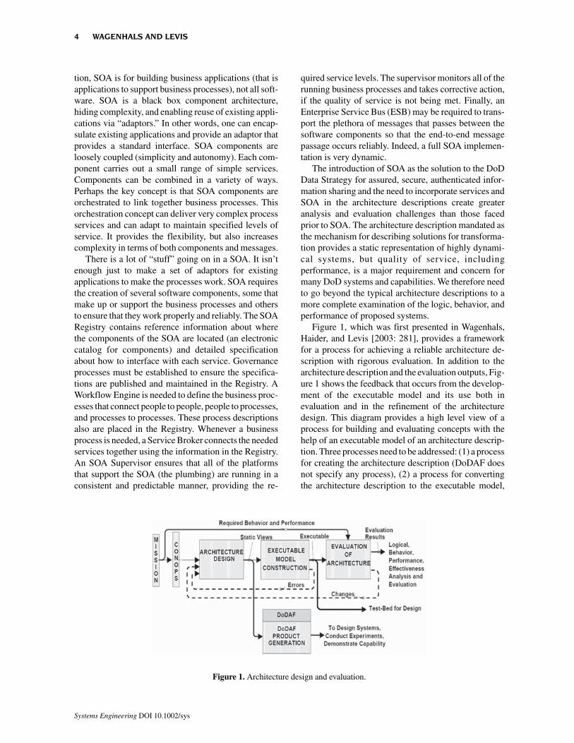
Figure 1, which was first presented in Wagenhals,Haider, and Levis [2003: 281], provides a frameworkfor a process for achieving a reliable architecture de-scription with rigorous evaluation. In addition to thearchitecture description and the evaluation outputs, Fig-ure 1 shows the feedback that occurs from the develop-ment of the executable model and its use both inevaluation and in the refinement of the architecturedesign. This diagram provides a high level view of aprocess for building and evaluating concepts with thehelp of an executable model of an architecture descrip-tion. Three processes need to be addressed: (1) a processfor creating the architecture description (DoDAF doesnot specify any process), (2) a process for convertingthe architecture description to the executable model,
Figure 1. Architecture design and evaluation.
4 WAGENHALS AND LEVIS
Systems Engineering DOI 10.1002/sys
and (3) a process for using the executable model foranalysis and evaluation.
The architecture creation process relies on one oftwo prevalent methodologies, Object Orientation andStructured Analysis. Either methodology can produceall the information needed for conversion to the ex-ecutable model [Wagenhals et al., 2000] and [Wagen-hals, Haider, and Levis, 2003], but care must be takento follow procedures that ensure all the needed data arecaptured. A key concept is that all elements of theexecutable model must be traceable to elements in thearchitecture description. As more is learned about thebehavior and performance of the architecture from thecreation of the executable model and the detailed analy-sis of behavior, any changes detected using the ex-ecutable model are used to modify the architecturedescription. Discrete event dynamical system modelsare appropriate for the executable model, and the Col-ored Petri Net (CPN) is a sufficiently general and rig-orous model [http://wiki.daimi.au.dk/cpntools/cpntools.wiki]. Other modeling approaches such asState Machines, Queuing Models, Automata, etc. canbe used, but CPNs subsume all of these. CPNs were
chosen because they are graph theoretic, executable,and enable both simulation and analysis of properties.They are rigorous in the way they handle concurrent andasynchronous events. Once created, the executablemodel can be used to support logical, behavioral, andperformance evaluations as will be described in Section4.
3. PROCESS DESCRIPTIONS
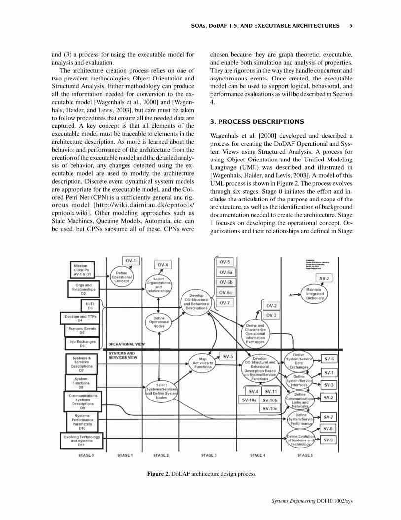
Wagenhals et al. [2000] developed and described aprocess for creating the DoDAF Operational and Sys-tem Views using Structured Analysis. A process forusing Object Orientation and the Unified ModelingLanguage (UML) was described and illustrated in[Wagenhals, Haider, and Levis, 2003]. A model of thisUML process is shown in Figure 2. The process evolvesthrough six stages. Stage 0 initiates the effort and in-cludes the articulation of the purpose and scope of thearchitecture, as well as the identification of backgrounddocumentation needed to create the architecture. Stage1 focuses on developing the operational concept. Or-ganizations and their relationships are defined in Stage
Figure 2. DoDAF architecture design process.
SOAs, DoDAF 1.5, AND EXECUTABLE ARCHITECTURES 5
Systems Engineering DOI 10.1002/sys
2 along with an initial sketch of the system nodes andlinks of the Systems and Services View. Stage 3 involvesa full analysis of the Operational View. If Object Orien-tation is used, both structure and behavior diagrams aredeveloped to understand and describe the operationalactivities carried out by organizations and the informa-tion that needs to be generated and exchanged. If Struc-tured Analysis is used, this analysis is accomplishedusing activity, data, rule, and dynamics models. Stage3 also turns to the Systems and Services View bydeveloping mappings from the operational activities tothe systems, services and system functions. In Stage 4,summary Operational View products are generated, andthe detailed analysis effort shifts to the Systems andServices View. The same Object Oriented or StructuredAnalysis techniques are used, but the focus is on systemcomponents and their functions along with system datathat is exchanged. In the last stage, Stage 5, the architectextracts data and concepts from the Stage 4 analysis andgenerates system and service interface descriptions, thecommunications infrastructure description, the systemand service performance parameters documentation,and the system, service, and technology evolution de-scriptions.
Both Structured Analysis and Object Orientationbased on UML can produce a complete architecturedescription conformant to the DoDAF products. Bothwill describe the same operational activities, informa-tion exchanges, operations nodes, etc. in the Opera-tional View, and the same systems, services, nodes,interfaces, data exchanges, and communications sys-tems, in the Systems and Services View. When usingStructured Analysis, the key models are activity models(IDEF0 or Data Flow Diagrams), data models (e.g.,IDEF1X or Entity Relationship Diagrams), rule mod-els, and dynamic models (e.g., state charts and eventtraces). If Object Orientation is used, structural dia-grams (class, component, and deployment diagrams)and behavior diagrams (activity, state machine, andsequence diagrams) are developed. Some of the UMLproducts look different than products developed usingStructured Analysis models, but the concept content isthe same.
In following the process described in Figure 2, thedevelopment of the architecture must adhere to certaindesign constraints in order for the architecture data tobe converted into the CPN executable model using thetechniques described in Wagenhals et al. [2000: 230–236] and Wagenhals, Haider, and Levis [2003: 275–278]. This means that both the Operational and theSystems and Services Views must be designed to carryout the operational concept. The views must include allactivities or functions and their relationships, define allof the information or data exchanges (messages), and
express the logic of each activity or function. Thisarchitecture data are used to produce the CPN with thefunctions being modeled as transitions and the relation-ships between the functions using directed arcs andplaces. The color set declarations for the tokens in eachplace are obtained from data descriptions, and the logicdescriptions are used as arc inscriptions or guard func-tions. These architecture data are contained in bothStructured Analysis and UML models, although theformat is different. This means that a Structured Analy-sis derived CPN will not appear to be identical to onederived from a UML description of the same architec-ture, but since the same functions, relationships, data,and logic will be described, the behavior of the twoshould be identical. Concordance must be maintainedwherein consistency and completeness are assuredacross all of the data and the descriptions that arecreated using the various UML or Structured Analysisdiagrams.
Once the executable model has been created, it canbe used to address, in part, the following layered ques-tions: (1) Is the architecture logically correct? (2) Doesthe architecture exhibit the desired behavior? (3) Arethe instantiations of the architecture in the Systems andServices View consistent with the Operational View?(4) Do instantiations of this architecture exhibit thedesired performance characteristics? (5) Do systemsbuilt in conformance to the architecture provide thedesired capability? (6) Can we analyze alternatives?
The construction of the executable model, especiallyof the one based on the operational view, provides thebasis for checking the logical consistency and correct-ness. The first step is to validate the logic of the model.The static views describe the structure, data, and rulesthat manipulate that data to accomplish tasks. We needto verify that the combination of rules, data, and struc-ture “works,” e.g., the rules are consistent and complete.This can be accomplished by executing the model to besure that it runs properly. In a sense, we are “debugging”the architecture. Any errors found must be corrected inthe appropriate static views to preserve traceability.
We can execute the model using notional inputs todetermine whether activities do indeed use data speci-fied by the information exchange requirements.“Flaws” can result in either an incorrect response or adeadlock. We can test the sequence of events; i.e., doesthe executable model produce the sequences specifiedby the sequence diagrams? And we can see whether theexecution of activities is a correct implementation of theoperational concept.
Once we verify that the executable model runs prop-erly we can examine the behavior of the architecture;this is an examination of the functionality of the archi-tecture. The behavior of the executable model and the
6 WAGENHALS AND LEVIS
Systems Engineering DOI 10.1002/sys
behavioral diagrams should correlate. This behaviorevaluation has several facets: Does the architectureproduce all the correct output for a given stimulus?Does the information arrive at the right functions in theright sequence, i.e., are the inputs processed in therequired way? The behavior of the architecture can becompared to the user’s requirements.
The behavioral correctness can be approached fromtwo perspectives: the operational perspective and thesystems and services perspective. For the operationalperspective, scenarios are developed and executed todetermine whether the desired behaviors (as reflectedin the state charts or event traces) are obtained. What isof particular interest here is the identification of unde-sired behaviors or the possibility of undesired states.Note that state transition descriptions (OV-6b and SV-10b) and the event trace descriptions (OV-6c and SV-10c) capture only a few of the desired behaviors. A realsystem may exhibit many more behaviors and the useof an executable model is one way of determining them.If CPNs are used for the executable model, then algo-rithms based on invariants can be used to relate thestructure of the model to its behavior [Valraud andLevis, 1991].
Once behavioral correctness has been established,performance can be examined. With DoDAF architec-tures, performance of the implementation of an archi-tecture can be evaluated only through the use of theexecutable model derived from the architecture data inthe systems and services view. The performance pa-rameters of the systems and services used to implementthe architecture are obtained from the Systems/ServicesPerformance Matrix (SV-7). Scenarios need to be de-veloped that are consistent with the use cases. Datacollected from simulation can be used to compute rele-vant Measures of Performance (MOPs).
CPNs offer more that just simulation to support theanalysis and evaluation. CPNs in general (andCPNTools [2008] in particular) allow behavioral prop-erties to be verified by analysis without resorting to
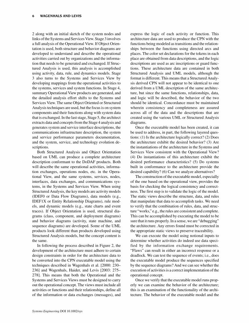
simulation. State Space Analysis is an analysis tech-nique that provides a variety of properties about a CPN[Kristensen, Christensen, and Jensen, 1998: 122–129].State Space Analysis techniques have been imple-mented in CPNTools. While each simulation run of theexecutable model shows particular sequence or trajec-tory of processing for a given input set, State SpaceAnalysis shows all possible trajectories for a giveninput. State Space Analysis provides a detailed look atall possible sequences of states that can occur given aspecific input set. Thus, it can be used to see if it ispossible for a set of inputs to generate undesired se-quences or outputs. In addition, State Space Analysiscan determine several important properties of the statespace of a CPN model. These include statistics such asthe total number of states and transitions between states,liveness properties such as the number and identity offinal states, and the number and identity of CPN transi-tions that can never fire in any sequence. The analysisdetermines boundedness properties that identify theminimum and maximum number and type of tokens (aCPN representation of an instance of data, e.g., mes-sages) that occur in each place. It also captures themarking (distribution of tokens) for any state includingthe final states so that these can be examined. Figure 3illustrates the relationships that can exist between theArchitecture Description and its executable model asthe latter is used both in simulation and State SpaceAnalysis.
It is important to understand that building the ex-ecutable model does not provide in itself an evaluation.The logical, behavioral, and performance aspects de-scribed above outline the steps of a process for evalu-ation, and the executable model becomes an importanttool in that process. Each step requires more effort andadditional information. One advantage of this stagedapproach is that one does not need to enter the detailsof the systems, a very laborious and costly undertaking,until the previous stages are completed satisfactorily.
Figure 3. Architecture evaluation with executable model.
SOAs, DoDAF 1.5, AND EXECUTABLE ARCHITECTURES 7
Systems Engineering DOI 10.1002/sys
4. CASE STUDY
A Case Study has been created to demonstrate theprocess for completing a full DoDAF 1.5 compliantarchitecture. It is based on a hypothetical operationalconcept for a new Theater Ballistic Missile Defense(TBMD) system called the Airborne TBM InterceptSystem (ATIS). It is not an accurate description of sucha system—it has been created for the express purposeof illustrating the architecture design process, espe-cially the case where incorporating new informationtechnology (e.g., net centric concepts and a modifiedinterceptor missile) in existing large legacy systemsprovides a new capability. It was assumed that thearchitecture will be used to inform decision-makersabout the nature of a new TBMD system and some ofthe tradeoffs involved in building one.
All DoDAF 1.5 products were produced using thepreviously described process; both Object Orientation(using UML) and Structure Analysis were used to illus-trate the techniques for both methodologies. An Ex-ecutable model using CPNs and the CPNTools softwarewas created for the Operational View. Logical, behav-ior, and high level performance evaluations were ac-complished using the simulation capabilities of the tool.We describe the process for creating the DODAF 1.5All View 1 product, plus all of the Operational andSystem and Services View products. We will illustratethe conversion to the CPN and the use of the CPN toperform the analysis.
As shown in Figure 2, the first part (Stage 0) of theprocess involves the collection of data and informationthat is pertinent to the architecture. This includes anydescription of the operational concept, potential opera-tional activities from authoritative sources such as theUniversal Joint Task Lists [2002], doctrine, tactics,techniques, and procedures, etc. It also includes infor-mation about systems, services, and communicationsnetworks. During Stage 0, it is imperative that thearchitect or architecting team establish the purpose andthe scope of the architecture description. The purposedefines the questions that the architecture descriptionwill answer and the time frame of the architecture. Inthe case study, the purpose was to develop an under-standing of the arrangement and interoperation of or-ganizations and systems that support the concept ofoperations for ATIS. The architecture is designed todetermine if the operational concept can be made towork and to assess the impact of evolving this systeminto the Net Centric Environment including its evolu-tion to incorporate Net Centric Enterprise Services andcreate special services of its own. An additional goal isto be able to assess the ability of the proposed systemto destroy incoming TBMs based on the capabilities of
Adversary A and B to launch them. Since we haveknowledge about the individual TBMs, but do not knowexactly how many TBMs each adversary has or howmany can be launched at one time, we need to boundthe problem and define how many ATIS assets will beneeded to give us the capability to defeat them. Supple-menting the purpose is a point of view; in this case, itis that of the ATIS Commander who would understandall of the operating procedures and know the basicsystems. The scope includes a time frame between 2010and 2015. All of this initial analysis, i.e. purpose, scope,and reference data will be cataloged in the All ViewOverview and Summary Information (AV-1). After thearchitecture has been completed the results of the analy-sis also will be included in the AV-1.
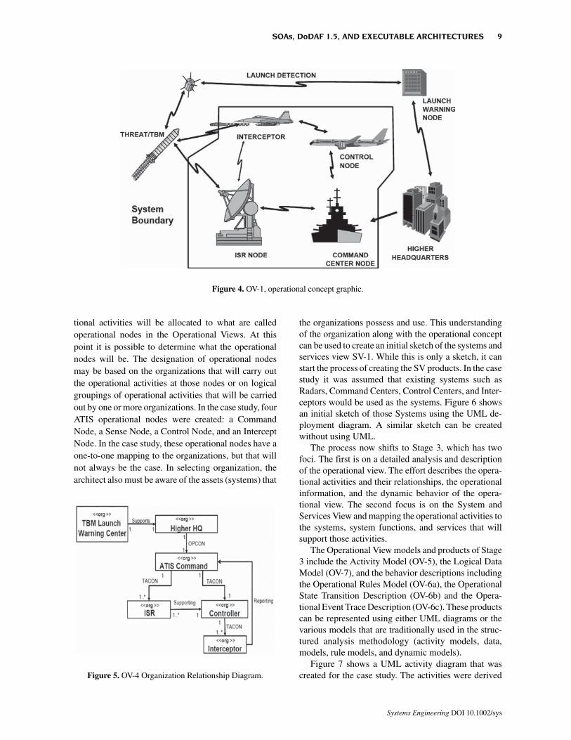
In Stage 1 of the basic process, the architect developsthe operational concept and creates both a graphic anda textual description. This becomes the OV-1, Opera-tional Concept Graphic product. Figure 4 show theOperational Concept graphic. Note that the elements ofthe graphic represent types of operational nodes notsystems. Of course, in a system like ATIS, the opera-tional concept will rely heavily on systems (Radar,Interceptors, Command Centers, etc.), but it is impor-tant not to constrain the design of the material solutionby specifying exact systems in the operational concept.Indeed, the concept could support a nontraditional air-borne laser “interceptor” where the “missile” is a lasershot. This OV-1 would not need to be modified signifi-cantly to support this material solution. Note that theboundary of the ATIS architecture has been depicted inthe graphic to distinguish what the ATIS architecture iscomposed of as well as the entities that will be externalto ATIS but that will interact with it. The textual descrip-tion explains that the operational concept is based onthe use of existing legacy systems that will be givenmodifications to support the concept of interceptingTactical Ballistic Missiles using modified interceptorsand interceptor missiles.
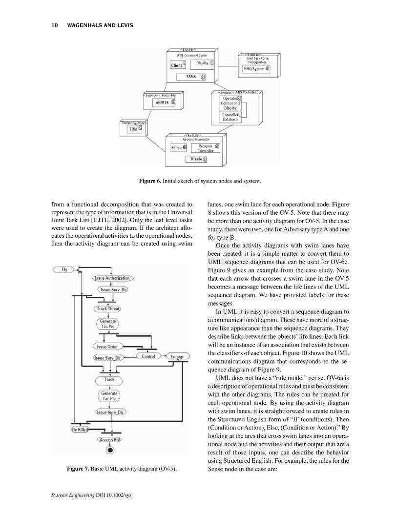
In Stage 2 of the basic process, the architect deter-mines the organizations that will execute the opera-tional concept and the relationships that will existbetween those organizations. Figure 5 shows the OV-4,the Organization Relationship Diagram. The UML for-mat is shown. If Structured Analysis is used, the result-ing diagram would be very similar. It would not havethe UML symbology for the relationships between theorganization, but rather different styles of lines to showthe different types of relationship. Understanding theserelationships is key to most military command andcontrol architectures.
The organizations will provide the operators who areresponsible for performing the operational activitiesthat will be defined in other OV products. These opera-
8 WAGENHALS AND LEVIS
Systems Engineering DOI 10.1002/sys
tional activities will be allocated to what are calledoperational nodes in the Operational Views. At thispoint it is possible to determine what the operationalnodes will be. The designation of operational nodesmay be based on the organizations that will carry outthe operational activities at those nodes or on logicalgroupings of operational activities that will be carriedout by one or more organizations. In the case study, fourATIS operational nodes were created: a CommandNode, a Sense Node, a Control Node, and an InterceptNode. In the case study, these operational nodes have aone-to-one mapping to the organizations, but that willnot always be the case. In selecting organization, thearchitect also must be aware of the assets (systems) that
the organizations possess and use. This understandingof the organization along with the operational conceptcan be used to create an initial sketch of the systems andservices view SV-1. While this is only a sketch, it canstart the process of creating the SV products. In the casestudy it was assumed that existing systems such asRadars, Command Centers, Control Centers, and Inter-ceptors would be used as the systems. Figure 6 showsan initial sketch of those Systems using the UML de-ployment diagram. A similar sketch can be createdwithout using UML.
The process now shifts to Stage 3, which has twofoci. The first is on a detailed analysis and descriptionof the operational view. The effort describes the opera-tional activities and their relationships, the operationalinformation, and the dynamic behavior of the opera-tional view. The second focus is on the System andServices View and mapping the operational activities tothe systems, system functions, and services that willsupport those activities.
The Operational View models and products of Stage3 include the Activity Model (OV-5), the Logical DataModel (OV-7), and the behavior descriptions includingthe Operational Rules Model (OV-6a), the OperationalState Transition Description (OV-6b) and the Opera-tional Event Trace Description (OV-6c). These productscan be represented using either UML diagrams or thevarious models that are traditionally used in the struc-tured analysis methodology (activity models, data,models, rule models, and dynamic models).
Figure 7 shows a UML activity diagram that wascreated for the case study. The activities were derived
Figure 4. OV-1, operational concept graphic.
Figure 5. OV-4 Organization Relationship Diagram.
SOAs, DoDAF 1.5, AND EXECUTABLE ARCHITECTURES 9
Systems Engineering DOI 10.1002/sys
from a functional decomposition that was created torepresent the type of information that is in the UniversalJoint Task List [UJTL, 2002]. Only the leaf level taskswere used to create the diagram. If the architect allo-cates the operational activities to the operational nodes,then the activity diagram can be created using swim
lanes, one swim lane for each operational node. Figure8 shows this version of the OV-5. Note that there maybe more than one activity diagram for OV-5. In the casestudy, there were two, one for Adversary type A and onefor type B.
Once the activity diagrams with swim lanes havebeen created, it is a simple matter to convert them toUML sequence diagrams that can be used for OV-6c.Figure 9 gives an example from the case study. Notethat each arrow that crosses a swim lane in the OV-5becomes a message between the life lines of the UMLsequence diagram. We have provided labels for thesemessages.
In UML it is easy to convert a sequence diagram toa communications diagram. These have more of a struc-ture like appearance than the sequence diagrams. Theydescribe links between the objects’ life lines. Each linkwill be an instance of an association that exists betweenthe classifiers of each object. Figure 10 shows the UMLcommunications diagram that corresponds to the se-quence diagram of Figure 9.
UML does not have a “rule model” per se. OV-6a isa description of operational rules and must be consistentwith the other diagrams. The rules can be created foreach operational node. By using the activity diagramwith swim lanes, it is straightforward to create rules inthe Structured English form of “IF (conditions), Then(Condition or Action), Else, (Condition or Action).” Bylooking at the arcs that cross swim lanes into an opera-tional node and the activities and their output that are aresult of those inputs, one can describe the behaviorusing Structured English. For example, the rules for theSense node in the case are:Figure 7. Basic UML activity diagram (OV-5).
Figure 6. Initial sketch of system nodes and system.
10 WAGENHALS AND LEVIS
Systems Engineering DOI 10.1002/sys
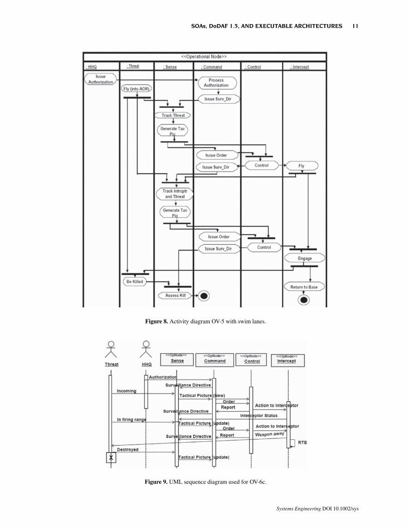
Figure 8. Activity diagram OV-5 with swim lanes.
Figure 9. UML sequence diagram used for OV-6c.
SOAs, DoDAF 1.5, AND EXECUTABLE ARCHITECTURES 11
Systems Engineering DOI 10.1002/sys
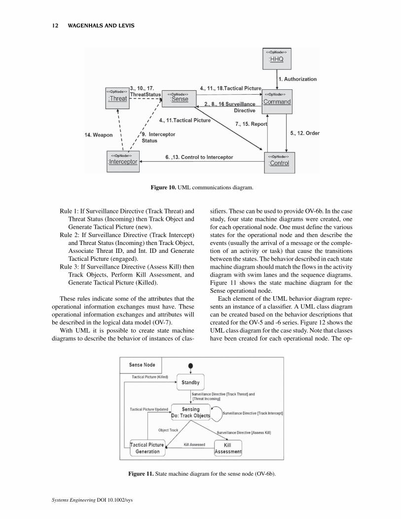
Rule 1: If Surveillance Directive (Track Threat) andThreat Status (Incoming) then Track Object andGenerate Tactical Picture (new).
Rule 2: If Surveillance Directive (Track Intercept)and Threat Status (Incoming) then Track Object,Associate Threat ID, and Int. ID and GenerateTactical Picture (engaged).
Rule 3: If Surveillance Directive (Assess Kill) thenTrack Objects, Perform Kill Assessment, andGenerate Tactical Picture (Killed).
These rules indicate some of the attributes that theoperational information exchanges must have. Theseoperational information exchanges and attributes willbe described in the logical data model (OV-7).
With UML it is possible to create state machinediagrams to describe the behavior of instances of clas-
sifiers. These can be used to provide OV-6b. In the casestudy, four state machine diagrams were created, onefor each operational node. One must define the variousstates for the operational node and then describe theevents (usually the arrival of a message or the comple-tion of an activity or task) that cause the transitionsbetween the states. The behavior described in each statemachine diagram should match the flows in the activitydiagram with swim lanes and the sequence diagrams.Figure 11 shows the state machine diagram for theSense operational node.
Each element of the UML behavior diagram repre-sents an instance of a classifier. A UML class diagramcan be created based on the behavior descriptions thatcreated for the OV-5 and -6 series. Figure 12 shows theUML class diagram for the case study. Note that classeshave been created for each operational node. The op-
Figure 10. UML communications diagram.
Figure 11. State machine diagram for the sense node (OV-6b).
12 WAGENHALS AND LEVIS
Systems Engineering DOI 10.1002/sys
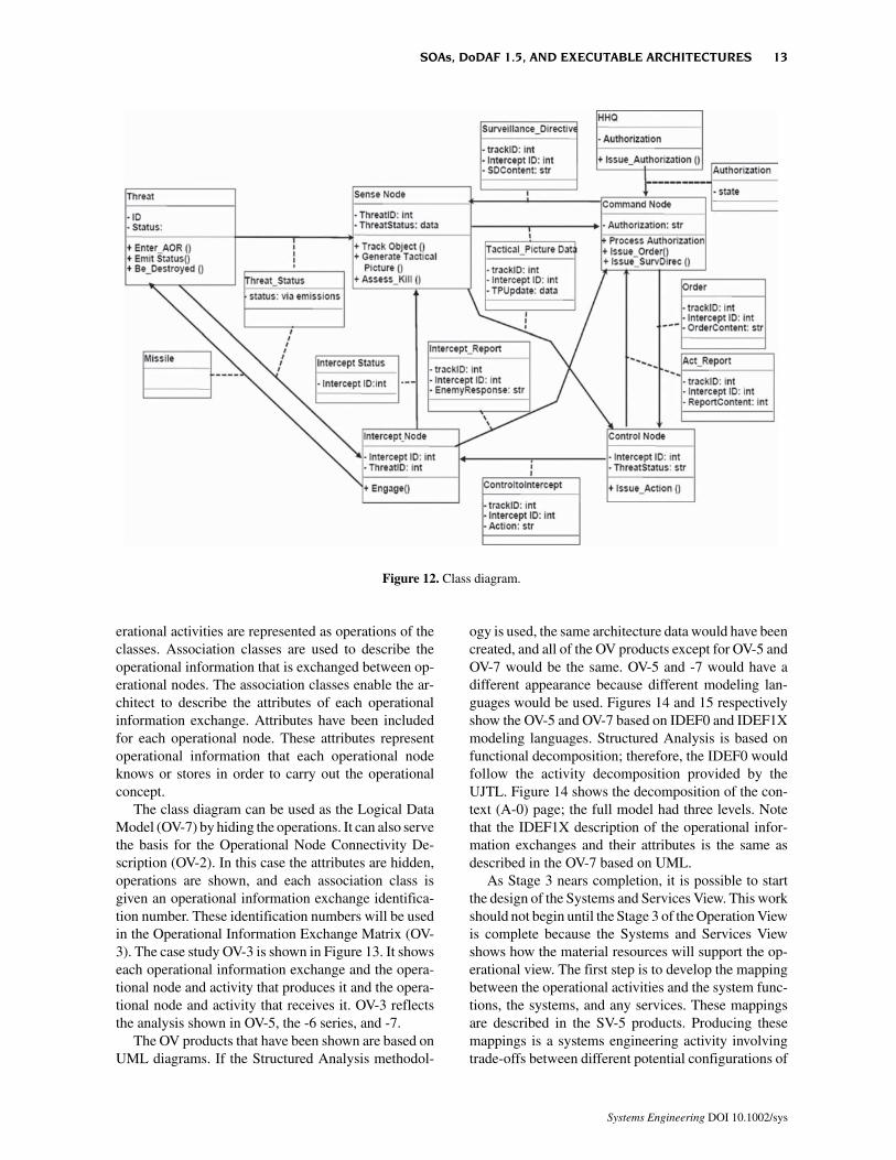
erational activities are represented as operations of theclasses. Association classes are used to describe theoperational information that is exchanged between op-erational nodes. The association classes enable the ar-chitect to describe the attributes of each operationalinformation exchange. Attributes have been includedfor each operational node. These attributes representoperational information that each operational nodeknows or stores in order to carry out the operationalconcept.
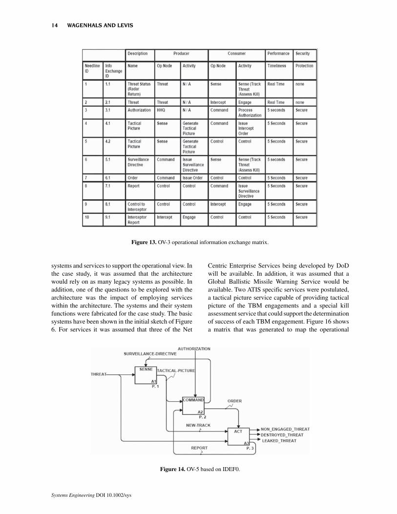
The class diagram can be used as the Logical DataModel (OV-7) by hiding the operations. It can also servethe basis for the Operational Node Connectivity De-scription (OV-2). In this case the attributes are hidden,operations are shown, and each association class isgiven an operational information exchange identifica-tion number. These identification numbers will be usedin the Operational Information Exchange Matrix (OV-3). The case study OV-3 is shown in Figure 13. It showseach operational information exchange and the opera-tional node and activity that produces it and the opera-tional node and activity that receives it. OV-3 reflectsthe analysis shown in OV-5, the -6 series, and -7.
The OV products that have been shown are based onUML diagrams. If the Structured Analysis methodol-
ogy is used, the same architecture data would have beencreated, and all of the OV products except for OV-5 andOV-7 would be the same. OV-5 and -7 would have adifferent appearance because different modeling lan-guages would be used. Figures 14 and 15 respectivelyshow the OV-5 and OV-7 based on IDEF0 and IDEF1Xmodeling languages. Structured Analysis is based onfunctional decomposition; therefore, the IDEF0 wouldfollow the activity decomposition provided by theUJTL. Figure 14 shows the decomposition of the con-text (A-0) page; the full model had three levels. Notethat the IDEF1X description of the operational infor-mation exchanges and their attributes is the same asdescribed in the OV-7 based on UML.
As Stage 3 nears completion, it is possible to startthe design of the Systems and Services View. This workshould not begin until the Stage 3 of the Operation Viewis complete because the Systems and Services Viewshows how the material resources will support the op-erational view. The first step is to develop the mappingbetween the operational activities and the system func-tions, the systems, and any services. These mappingsare described in the SV-5 products. Producing thesemappings is a systems engineering activity involvingtrade-offs between different potential configurations of
Figure 12. Class diagram.
SOAs, DoDAF 1.5, AND EXECUTABLE ARCHITECTURES 13
Systems Engineering DOI 10.1002/sys
systems and services to support the operational view. Inthe case study, it was assumed that the architecturewould rely on as many legacy systems as possible. Inaddition, one of the questions to be explored with thearchitecture was the impact of employing serviceswithin the architecture. The systems and their systemfunctions were fabricated for the case study. The basicsystems have been shown in the initial sketch of Figure6. For services it was assumed that three of the Net
Centric Enterprise Services being developed by DoDwill be available. In addition, it was assumed that aGlobal Ballistic Missile Warning Service would beavailable. Two ATIS specific services were postulated,a tactical picture service capable of providing tacticalpicture of the TBM engagements and a special killassessment service that could support the determinationof success of each TBM engagement. Figure 16 showsa matrix that was generated to map the operational
Figure 13. OV-3 operational information exchange matrix.
Figure 14. OV-5 based on IDEF0.
14 WAGENHALS AND LEVIS
Systems Engineering DOI 10.1002/sys
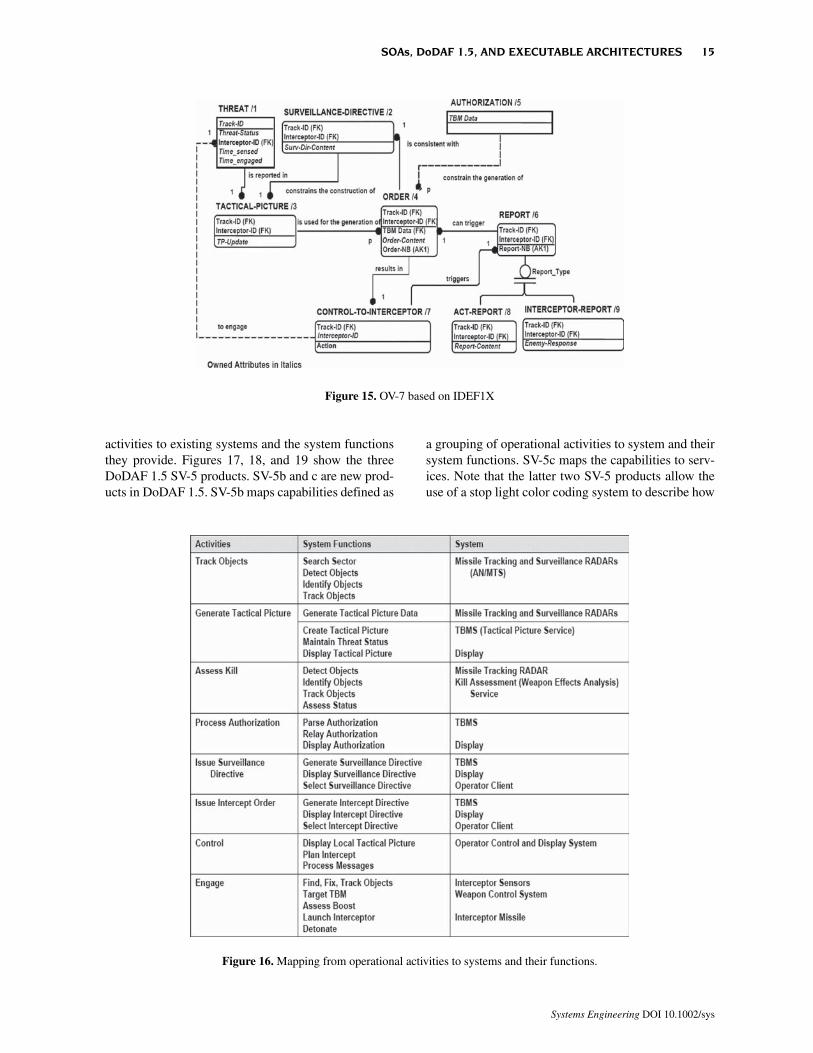
activities to existing systems and the system functionsthey provide. Figures 17, 18, and 19 show the threeDoDAF 1.5 SV-5 products. SV-5b and c are new prod-ucts in DoDAF 1.5. SV-5b maps capabilities defined as
a grouping of operational activities to system and theirsystem functions. SV-5c maps the capabilities to serv-ices. Note that the latter two SV-5 products allow theuse of a stop light color coding system to describe how
Figure 15. OV-7 based on IDEF1X
Figure 16. Mapping from operational activities to systems and their functions.
SOAs, DoDAF 1.5, AND EXECUTABLE ARCHITECTURES 15
Systems Engineering DOI 10.1002/sys
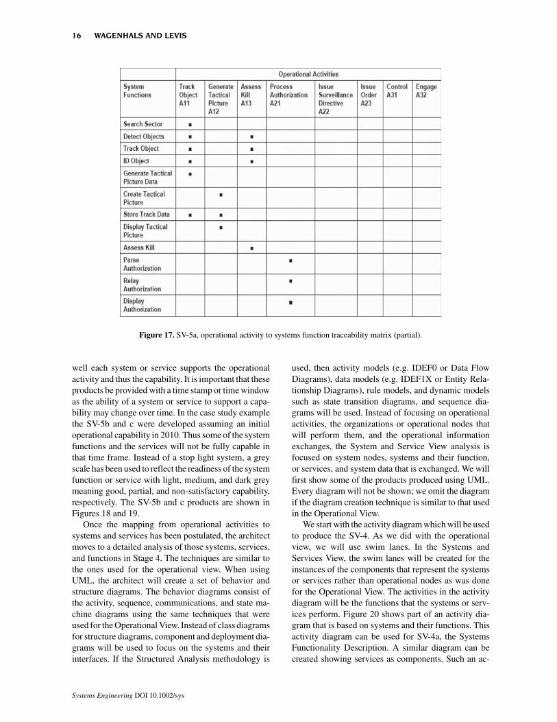
well each system or service supports the operationalactivity and thus the capability. It is important that theseproducts be provided with a time stamp or time windowas the ability of a system or service to support a capa-bility may change over time. In the case study examplethe SV-5b and c were developed assuming an initialoperational capability in 2010. Thus some of the systemfunctions and the services will not be fully capable inthat time frame. Instead of a stop light system, a greyscale has been used to reflect the readiness of the systemfunction or service with light, medium, and dark greymeaning good, partial, and non-satisfactory capability,respectively. The SV-5b and c products are shown inFigures 18 and 19.
Once the mapping from operational activities tosystems and services has been postulated, the architectmoves to a detailed analysis of those systems, services,and functions in Stage 4. The techniques are similar tothe ones used for the operational view. When usingUML, the architect will create a set of behavior andstructure diagrams. The behavior diagrams consist ofthe activity, sequence, communications, and state ma-chine diagrams using the same techniques that wereused for the Operational View. Instead of class diagramsfor structure diagrams, component and deployment dia-grams will be used to focus on the systems and theirinterfaces. If the Structured Analysis methodology is
used, then activity models (e.g. IDEF0 or Data FlowDiagrams), data models (e.g. IDEF1X or Entity Rela-tionship Diagrams), rule models, and dynamic modelssuch as state transition diagrams, and sequence dia-grams will be used. Instead of focusing on operationalactivities, the organizations or operational nodes thatwill perform them, and the operational informationexchanges, the System and Service View analysis isfocused on system nodes, systems and their function,or services, and system data that is exchanged. We willfirst show some of the products produced using UML.Every diagram will not be shown; we omit the diagramif the diagram creation technique is similar to that usedin the Operational View.
We start with the activity diagram which will be usedto produce the SV-4. As we did with the operationalview, we will use swim lanes. In the Systems andServices View, the swim lanes will be created for theinstances of the components that represent the systemsor services rather than operational nodes as was donefor the Operational View. The activities in the activitydiagram will be the functions that the systems or serv-ices perform. Figure 20 shows part of an activity dia-gram that is based on systems and their functions. Thisactivity diagram can be used for SV-4a, the SystemsFunctionality Description. A similar diagram can becreated showing services as components. Such an ac-
Figure 17. SV-5a, operational activity to systems function traceability matrix (partial).
16 WAGENHALS AND LEVIS
Systems Engineering DOI 10.1002/sys
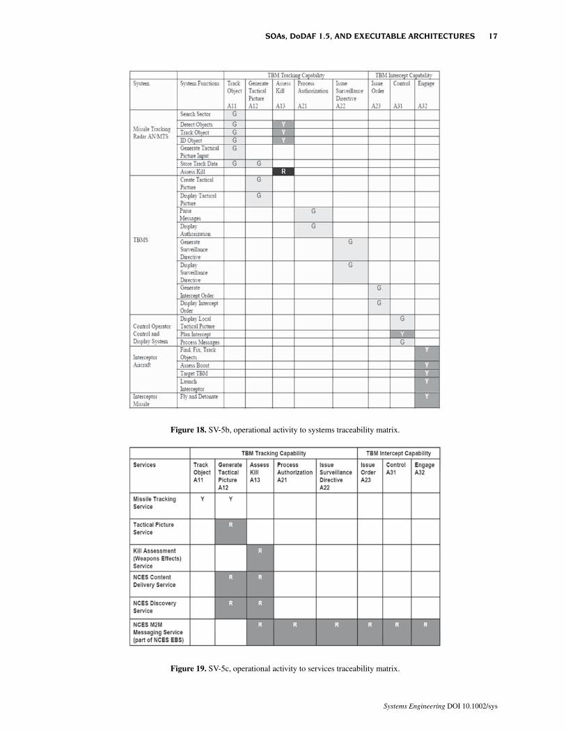
Figure 19. SV-5c, operational activity to services traceability matrix.
Figure 18. SV-5b, operational activity to systems traceability matrix.
SOAs, DoDAF 1.5, AND EXECUTABLE ARCHITECTURES 17
Systems Engineering DOI 10.1002/sys
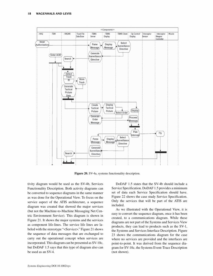
tivity diagram would be used as the SV-4b, ServicesFunctionality Description. Both activity diagrams canbe converted to sequence diagrams in the same manneras was done for the Operational View. To focus on theservice aspect of the ATIS architecture, a sequencediagram was created that showed the major services(but not the Machine-to-Machine Messaging Net Cen-tric Environment Service). This diagram is shown inFigure 21. It shows the major systems and the servicesas component life-lines. The service life lines are la-beled with the stereotype “<Service>.” Figure 21 showsthe sequence of data messages that are exchanged tocarry out the operational concept when services areincorporated. This diagram can be presented as SV-10c,but DoDAF 1.5 says that this type of diagram also canbe used as an SV-4.
DoDAF 1.5 states that the SV-4b should include aService Specification. DoDAF 1.5 provides a minimumset of data each Service Specification should have.Figure 22 shows the case study Service Specification.Only the services that will be part of the ATIS areincluded.
As we illustrated with the Operational View, it iseasy to convert the sequence diagram, once it has beencreated, to a communications diagram. While thesediagrams are not part of the Systems and Services Viewproducts, they can lead to products such as the SV-1,the Systems and Services Interface Description. Figure23 shows the communications diagram for the casewhere no services are provided and the interfaces arepoint-to-point. It was derived from the sequence dia-gram for SV-10c, the Systems Event-Trace Description(not shown).
Figure 20. SV-4a, systems functionality description.
18 WAGENHALS AND LEVIS
Systems Engineering DOI 10.1002/sys
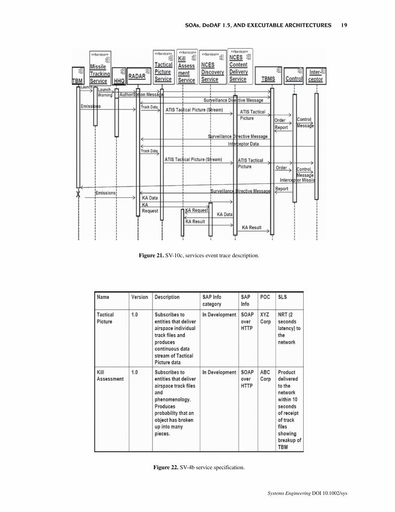
Figure 21. SV-10c, services event trace description.
Figure 22. SV-4b service specification.
SOAs, DoDAF 1.5, AND EXECUTABLE ARCHITECTURES 19
Systems Engineering DOI 10.1002/sys

Once communications diagrams are created, theycan be transformed into component diagrams that re-flect the interfaces between components that representsystems or services. Figures 24 and 25 show the basiccomponent diagrams for ATIS systems and services,respectively. Note that the UML artifact classifier hasbeen used to represent the system or service data ex-change messages. Figure 26 elaborates on the compo-nent diagram of Figure 24 showing provided andrequired interfaces and listing the system functions ofeach component. A similar diagram can be created forthe services.
The interfaces define the system data that must beexchanged in the Systems and Services View design.Further specification of the systems data can be cap-tured in the SV-11, the Physical Schema. Figure 27shows the case study SV-11.
This completes the Stage 4 effort. The SV 10a (Sys-tems/Services Rule Model) and SV-10b (Systems/Serv-ices State Transition Description) are created in thesame manner as was illustrated for OV-6a and b. Theywill not be shown here.
In Stage 5, the results of Stage 4 are summarized ina set of Systems and Services View products. Figures28 and 29 show the two versions of the SV-1 (Sys-tems/Service Interface Description). These are UMLdeployment diagrams and were derived from the com-ponent diagrams shown in Figures 24, 25, and 26. Notethat a key interface designation has been added to each
interface. These diagrams are analogous to the OV-2,Operational Node Connectivity Description. The de-tails of the system data exchanges will be described inSV-6, the Systems Data Exchange Matrix, which isanalogous to the OV-3. Details about each interface areprovided in the SV-3 product.
The case study SV-1 shows two concepts. The firstSV-1 shows the ATIS without services (other than theTBM Warning Service). The Radar sends and receivessystem data messages directly to and from the Com-mand Center systems. This design is tightly coupled,and system may need to be designed that way given thetime critical nature of the system. Adding servicesreduces coupling but increase complexity. The radarsends track data to the tactical picture service thatconverts into the ATIS tactical picture and posts it in theNCES Content Delivery Service. Users can subscribeto this content, and the users can include the other ATISsystem nodes. Furthermore, the ATIS Tactical PictureService may receive data from non-ATIS sensors thatcould enhance the tactical picture. The Kill AssessmentService is decoupled from the Radar (but it is shown aspart of the Radar system, although it could be locatedelsewhere). Instead of tightly coupled to the Radar, itcan be open to other inputs and processes that mayenhance the overall kill assessment product. In a com-plex SOA environment, the equivalent of a servicebroker might link together all of the services and dataproviders prior to any actual TBM intercept. The details
Figure 23. Systems communications diagram.
20 WAGENHALS AND LEVIS
Systems Engineering DOI 10.1002/sys
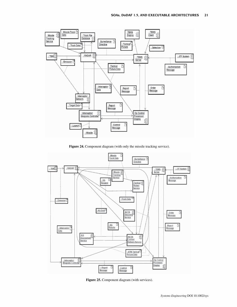
Figure 25. Component diagram (with services).
Figure 24. Component diagram (with only the missile tracking service).
SOAs, DoDAF 1.5, AND EXECUTABLE ARCHITECTURES 21
Systems Engineering DOI 10.1002/sys

of this type of SOA have not been included in thearchitecture description.
The SV-6 (Systems and Services Data ExchangeMatrices) are constructed in the same manner as theOV-3. Figure 30 shows part of this product that wasproduced for the Case Study. Other parts show Systemsand Services Data Exchanges.
The focus now shifts to the Systems/Services Com-munications Description (SV-2). Given the interfacesthat have been developed in the SV-4 and SV-1, thecommunications infrastructure description is devel-oped. Generally this will require expertise in commu-nications networks and systems. Figure 31 shows a highlevel description of this infrastructure that was createdfor the case study. Note that the connection to the NCESto reach the non-ATIS services is depicted as a satellitecommunications link. The time delays associated withthese links will need to be considered. If delays are too
long, the ATIS will not be fast enough to carry out theoperational concept. For the initial case study, veryshort time delays were assumed.
The SV-3 (Systems-Systems Matrix, Systems-Serv-ices Matrix, and Services-Services Matrix) defines theinterfaces, including communications that are depictedin the SV-1 and SV-2. A legend is created that providescodes for the different types of interfaces. Figure 32shows a portion of the case study Systems-SystemsMatrix. The Systems-Services and Services-Servicesmatrices of this product are not shown.
The remaining products, SV-7 (Systems/ServicesPerformance Parameter Matrix), SV-8 (Systems/Serv-ices Evolution Description), and SV-9 (Systems/Serv-ices Technology Forecast) show aspects of the evolutionof the architecture. Figures 33, 34, and 35 show theseproducts.
Figure 26. Component diagram (with interfaces).
22 WAGENHALS AND LEVIS
Systems Engineering DOI 10.1002/sys
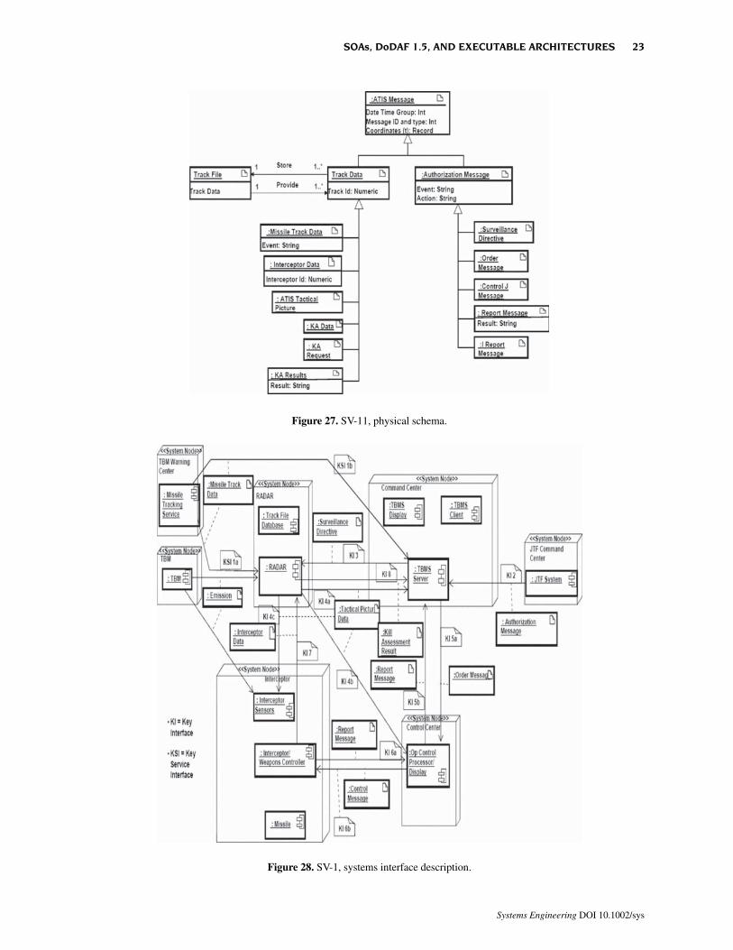
Figure 28. SV-1, systems interface description.
Figure 27. SV-11, physical schema.
SOAs, DoDAF 1.5, AND EXECUTABLE ARCHITECTURES 23
Systems Engineering DOI 10.1002/sys

Figure 30. SV-6, systems/services data exchange matrix (partial).
Figure 29. SV-1, services interface description.
24 WAGENHALS AND LEVIS
Systems Engineering DOI 10.1002/sys
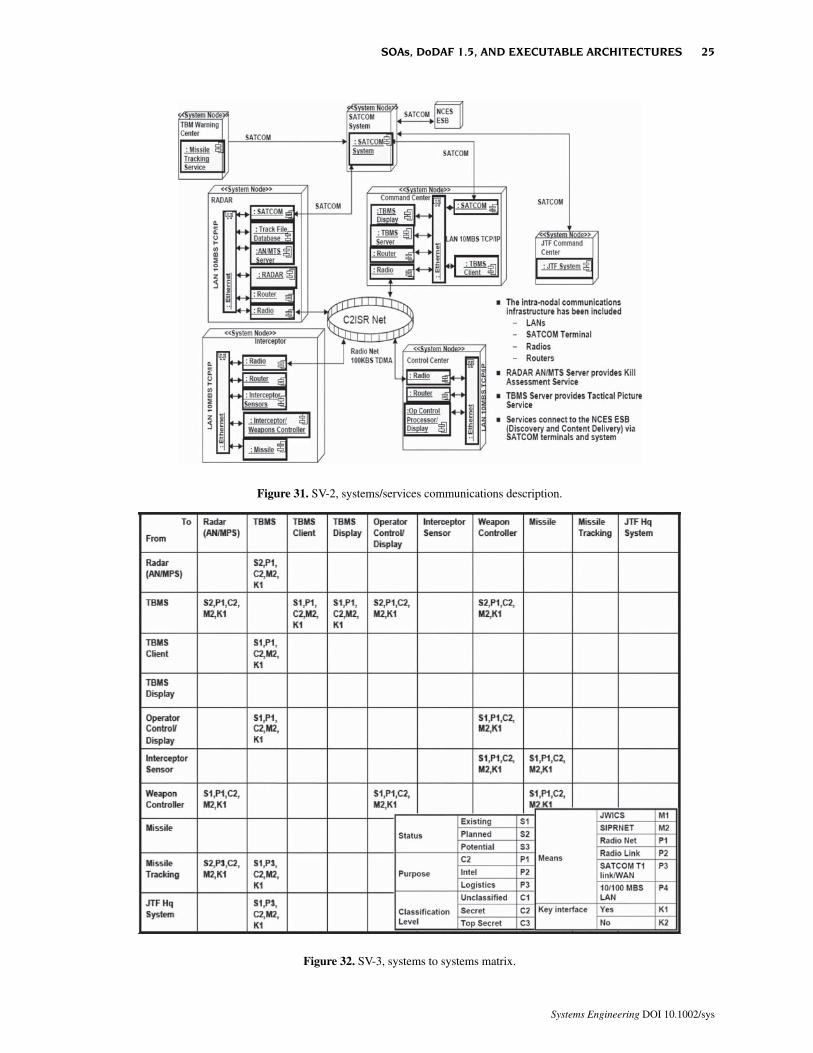
Figure 32. SV-3, systems to systems matrix.
Figure 31. SV-2, systems/services communications description.
SOAs, DoDAF 1.5, AND EXECUTABLE ARCHITECTURES 25
Systems Engineering DOI 10.1002/sys
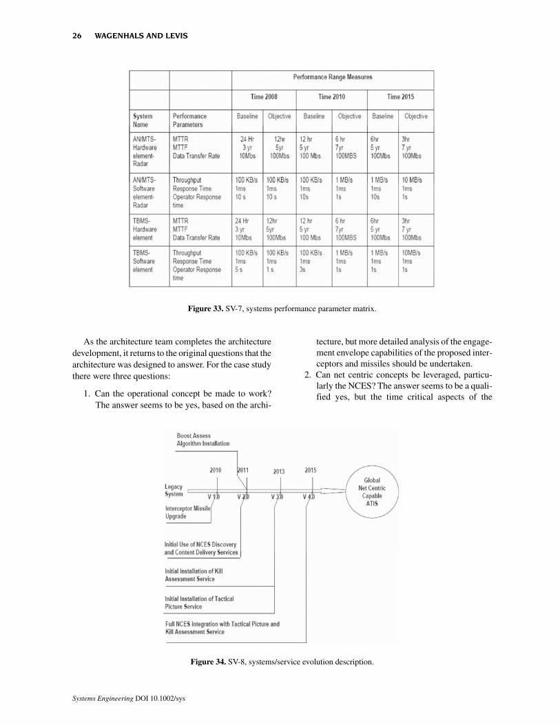
As the architecture team completes the architecturedevelopment, it returns to the original questions that thearchitecture was designed to answer. For the case studythere were three questions:
1. Can the operational concept be made to work?The answer seems to be yes, based on the archi-
tecture, but more detailed analysis of the engage-ment envelope capabilities of the proposed inter-ceptors and missiles should be undertaken.
2. Can net centric concepts be leveraged, particu-larly the NCES? The answer seems to be a quali-fied yes, but the time critical aspects of the
Figure 33. SV-7, systems performance parameter matrix.
Figure 34. SV-8, systems/service evolution description.
26 WAGENHALS AND LEVIS
Systems Engineering DOI 10.1002/sys
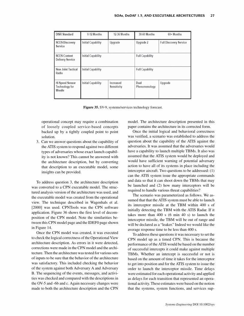
operational concept may require a combinationof loosely coupled service-based conceptsbacked up by a tightly coupled point to pointsolution.
3. Can we answer questions about the capability ofthe ATIS system to respond against two differenttypes of adversaries whose exact launch capabil-ity is not known? This cannot be answered withthe architecture description, but by convertingthat description to an executable model, someinsights can be provided.
To address question 3, the architecture descriptionwas converted to a CPN executable model. The struc-tured analysis version of the architecture was used, andthe executable model was created from the operationalview. The technique described in Wagenhals et al.[2000] was used. CPNTools was the CPN softwareapplication. Figure 36 shows the first level of decom-position of the CPN model. Note the similarities be-tween this CPN model page and the IDEF0 page shownin Figure 14.
Once the CPN model was created, it was executedto check the logical correctness of the Operational Viewarchitecture description. As errors in it were detected,corrections were made in the CPN model and the archi-tecture. Then the architecture was tested for various setsof inputs to be sure that the behavior of the architecturewas satisfactory. This included checking the behaviorof the system against both Adversary A and AdversaryB. The sequencing of the events, messages, and activi-ties was checked and compared with the descriptions inthe OV-5 and -6b and c. Again necessary changes weremade to both the architecture description and the CPN
model. The architecture description presented in thispaper contains the architecture in its corrected form.
Once the initial logical and behavioral correctnesswas verified, a scenario was established to address thequestion about the capability of the ATIS against theadversaries. It was assumed that the adversaries wouldhave a capability to launch multiple TBMs. It also wasassumed that the ATIS system would be deployed andwould have sufficient warning of potential adversaryaction to have all of its systems in place including theinterceptor aircraft. Two questions to be addressed: (1)can the ATIS system issue the appropriate commandsand data so that it can shoot down the TBMs that maybe launched and (2) how many interceptors will berequired to handle various threat capabilities?
The scenario was parameterized as follows. We as-sumed that that the ATIS system must be able to launchits interceptor missile at the TBM within 400 s ofinitially detecting the TBM with the ATIS Radar. If ittakes more than 400 s (6 min 40 s) to launch theinterceptor missile, the TBM will be out of range andwill be declared as a “leaker.” Indeed we would like theaverage response time to be less than 400 s.
To address these questions it was necessary to set theCPN model up as a timed CPN. This is because theperformance of the ATIS would be based on the numberof successful intercepts it could make against multipleTBMs. Whether an intercept is successful or not isbased on the amount of time it takes for the interceptorto get into position and for the ATIS system to issue theorder to launch the interceptor missile. Time delayswere estimated for each operational activity and appliedas delays for each transition that represented an opera-tional activity. These estimates were based on the notionthat the systems, system functions, and services sup-
Figure 35. SV-9, systems/services technology forecast.
SOAs, DoDAF 1.5, AND EXECUTABLE ARCHITECTURES 27
Systems Engineering DOI 10.1002/sys
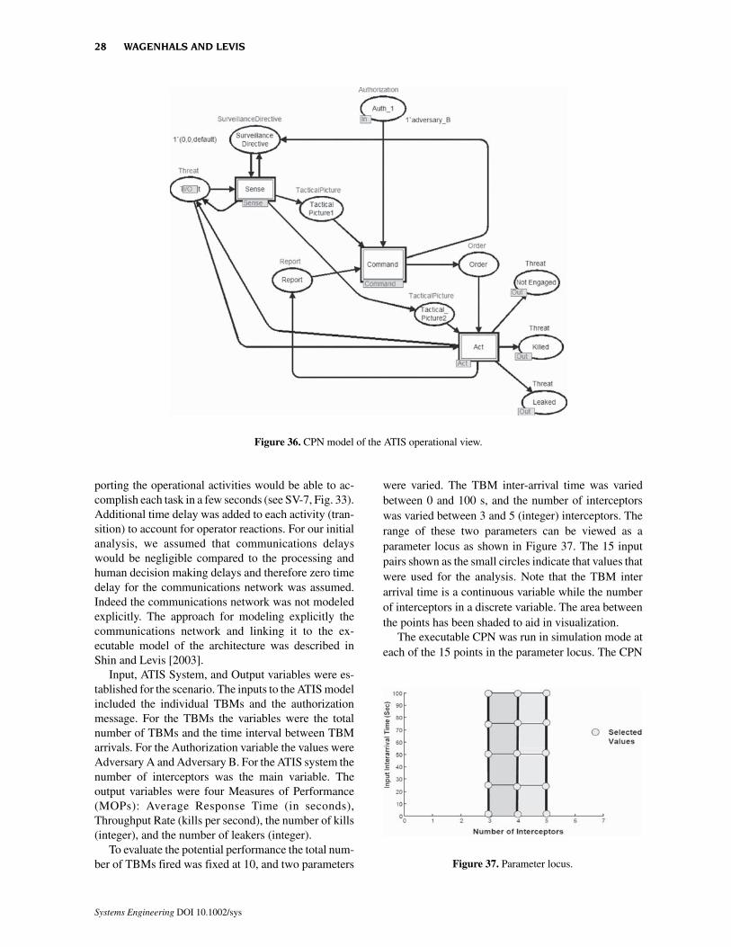
porting the operational activities would be able to ac-complish each task in a few seconds (see SV-7, Fig. 33).Additional time delay was added to each activity (tran-sition) to account for operator reactions. For our initialanalysis, we assumed that communications delayswould be negligible compared to the processing andhuman decision making delays and therefore zero timedelay for the communications network was assumed.Indeed the communications network was not modeledexplicitly. The approach for modeling explicitly thecommunications network and linking it to the ex-ecutable model of the architecture was described inShin and Levis [2003].
Input, ATIS System, and Output variables were es-tablished for the scenario. The inputs to the ATIS modelincluded the individual TBMs and the authorizationmessage. For the TBMs the variables were the totalnumber of TBMs and the time interval between TBMarrivals. For the Authorization variable the values wereAdversary A and Adversary B. For the ATIS system thenumber of interceptors was the main variable. Theoutput variables were four Measures of Performance(MOPs): Average Response Time (in seconds),Throughput Rate (kills per second), the number of kills(integer), and the number of leakers (integer).
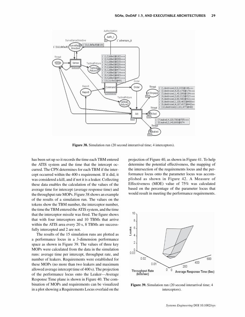
To evaluate the potential performance the total num-ber of TBMs fired was fixed at 10, and two parameters
were varied. The TBM inter-arrival time was variedbetween 0 and 100 s, and the number of interceptorswas varied between 3 and 5 (integer) interceptors. Therange of these two parameters can be viewed as aparameter locus as shown in Figure 37. The 15 inputpairs shown as the small circles indicate that values thatwere used for the analysis. Note that the TBM interarrival time is a continuous variable while the numberof interceptors in a discrete variable. The area betweenthe points has been shaded to aid in visualization.
The executable CPN was run in simulation mode ateach of the 15 points in the parameter locus. The CPN
Figure 37. Parameter locus.
Figure 36. CPN model of the ATIS operational view.
28 WAGENHALS AND LEVIS
Systems Engineering DOI 10.1002/sys
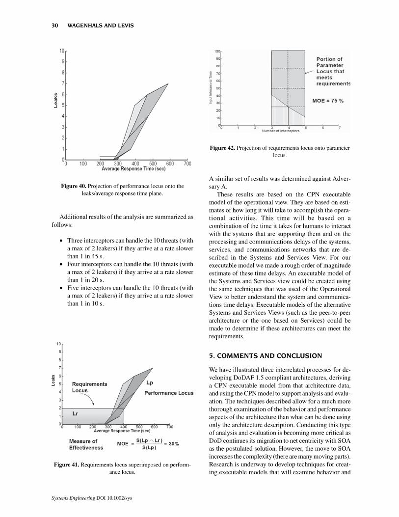
has been set up so it records the time each TBM enteredthe ATIS system and the time that the intercept oc-curred. The CPN determines for each TBM if the inter-cept occurred within the 400 s requirement. If it did, itwas considered a kill, and if not it is a leaker. Collectingthese data enables the calculation of the values of theaverage time for intercept (average response time) andthe throughput rate MOPs. Figure 38 shows an exampleof the results of a simulation run. The values on thetokens show the TBM number, the interceptor number,the time the TBM entered the ATIS system, and the timethat the interceptor missile was fired. The figure showsthat with four interceptors and 10 TBMs that arrivewithin the ATIS area every 20 s, 8 TBMs are success-fully intercepted and 2 are not.
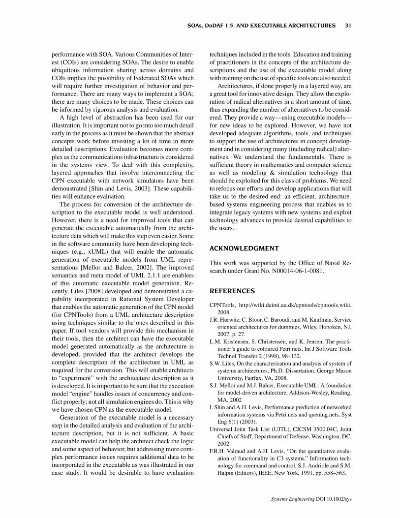
The results of the 15 simulation runs are plotted asa performance locus in a 3-dimension performancespace as shown in Figure 39. The values of three keyMOPs were calculated from the data in the simulationruns: average time per intercept, throughput rate, andnumber of leakers. Requirements were established forthese MOPs (no more than two leakers and maximumallowed average intercept time of 400 s). The projectionof the performance locus onto the Leaker—AverageResponse Time plane is shown in Figure 40. The com-bination of MOPs and requirements can be visualizedin a plot showing a Requirements Locus overlaid on the
projection of Figure 40, as shown in Figure 41. To helpdetermine the potential effectiveness, the mapping ofthe intersection of the requirements locus and the per-formance locus onto the parameter locus was accom-plished as shown in Figure 42. A Measure ofEffectiveness (MOE) value of 75% was calculatedbased on the percentage of the parameter locus thatwould result in meeting the performance requirements.
Figure 38. Simulation run (20 second interarrival time; 4 interceptors).
Figure 39. Simulation run (20 second interarrival time; 4interceptors).
SOAs, DoDAF 1.5, AND EXECUTABLE ARCHITECTURES 29
Systems Engineering DOI 10.1002/sys
Additional results of the analysis are summarized asfollows:
• Three interceptors can handle the 10 threats (witha max of 2 leakers) if they arrive at a rate slowerthan 1 in 45 s.
• Four interceptors can handle the 10 threats (witha max of 2 leakers) if they arrive at a rate slowerthan 1 in 20 s.
• Five interceptors can handle the 10 threats (witha max of 2 leakers) if they arrive at a rate slowerthan 1 in 10 s.
A similar set of results was determined against Adver-sary A.
These results are based on the CPN executablemodel of the operational view. They are based on esti-mates of how long it will take to accomplish the opera-tional activities. This time will be based on acombination of the time it takes for humans to interactwith the systems that are supporting them and on theprocessing and communications delays of the systems,services, and communications networks that are de-scribed in the Systems and Services View. For ourexecutable model we made a rough order of magnitudeestimate of these time delays. An executable model ofthe Systems and Services view could be created usingthe same techniques that was used of the OperationalView to better understand the system and communica-tions time delays. Executable models of the alternativeSystems and Services Views (such as the peer-to-peerarchitecture or the one based on Services) could bemade to determine if these architectures can meet therequirements.
5. COMMENTS AND CONCLUSION
We have illustrated three interrelated processes for de-veloping DoDAF 1.5 compliant architectures, derivinga CPN executable model from that architecture data,and using the CPN model to support analysis and evalu-ation. The techniques described allow for a much morethorough examination of the behavior and performanceaspects of the architecture than what can be done usingonly the architecture description. Conducting this typeof analysis and evaluation is becoming more critical asDoD continues its migration to net centricity with SOAas the postulated solution. However, the move to SOAincreases the complexity (there are many moving parts).Research is underway to develop techniques for creat-ing executable models that will examine behavior and
Figure 42. Projection of requirements locus onto parameterlocus.
Figure 41. Requirements locus superimposed on perform-ance locus.
Figure 40. Projection of performance locus onto theleaks/average response time plane.
30 WAGENHALS AND LEVIS
Systems Engineering DOI 10.1002/sys
performance with SOA. Various Communities of Inter-est (COIs) are considering SOAs. The desire to enableubiquitous information sharing across domains andCOIs implies the possibility of Federated SOAs whichwill require further investigation of behavior and per-formance. There are many ways to implement a SOA;there are many choices to be made. These choices canbe informed by rigorous analysis and evaluation.
A high level of abstraction has been used for ourillustration. It is important not to go into too much detailearly in the process as it must be shown that the abstractconcepts work before investing a lot of time in moredetailed descriptions. Evaluation becomes more com-plex as the communications infrastructure is consideredin the systems view. To deal with this complexity,layered approaches that involve interconnecting theCPN executable with network simulators have beendemonstrated [Shin and Levis, 2003]. These capabili-ties will enhance evaluation.
The process for conversion of the architecture de-scription to the executable model is well understood.However, there is a need for improved tools that cangenerate the executable automatically from the archi-tecture data which will make this step even easier. Somein the software community have been developing tech-niques (e.g., xUML) that will enable the automaticgeneration of executable models from UML repre-sentations [Mellor and Balcer, 2002]. The improvedsemantics and meta model of UML 2.1.1 are enablersof this automatic executable model generation. Re-cently, Liles [2008] developed and demonstrated a ca-pability incorporated in Rational System Developerthat enables the automatic generation of the CPN model(for CPNTools) from a UML architecture descriptionusing techniques similar to the ones described in thispaper. If tool vendors will provide this mechanism intheir tools, then the architect can have the executablemodel generated automatically as the architecture isdeveloped, provided that the architect develops thecomplete description of the architecture in UML asrequired for the conversion. This will enable architectsto “experiment” with the architecture description as itis developed. It is important to be sure that the executionmodel “engine” handles issues of concurrency and con-flict properly; not all simulation engines do. This is whywe have chosen CPN as the executable model.
Generation of the executable model is a necessarystep in the detailed analysis and evaluation of the archi-tecture description, but it is not sufficient. A basicexecutable model can help the architect check the logicand some aspect of behavior, but addressing more com-plex performance issues requires additional data to beincorporated in the executable as was illustrated in ourcase study. It would be desirable to have evaluation
techniques included in the tools. Education and trainingof practitioners in the concepts of the architecture de-scriptions and the use of the executable model alongwith training on the use of specific tools are also needed.
Architectures, if done properly in a layered way, area great tool for innovative design. They allow the explo-ration of radical alternatives in a short amount of time,thus expanding the number of alternatives to be consid-ered. They provide a way—using executable models—for new ideas to be explored. However, we have notdeveloped adequate algorithms, tools, and techniquesto support the use of architectures in concept develop-ment and in considering many (including radical) alter-natives. We understand the fundamentals. There issufficient theory in mathematics and computer scienceas well as modeling & simulation technology thatshould be exploited for this class of problems. We needto refocus our efforts and develop applications that willtake us to the desired end: an efficient, architecture-based systems engineering process that enables us tointegrate legacy systems with new systems and exploittechnology advances to provide desired capabilities tothe users.
ACKNOWLEDGMENT
This work was supported by the Office of Naval Re-search under Grant No. N00014-06-1-0081.
REFERENCES
CPNTools, http://wiki.daimi.au.dk/cpntools/cpntools.wiki,2008.
J.R. Hurwitz, C. Bloor, C. Baroudi, and M. Kaufman, Serviceoriented architectures for dummies, Wiley, Hoboken, NJ,2007, p. 27.
L.M. Kristensen, S. Christensen, and K. Jensen, The practi-tioner’s guide to coloured Petri nets, Int J Software ToolsTechnol Transfer 2 (1998), 98–132.
S.W. Liles, On the characterization and analysis of system ofsystems architectures, Ph.D. Dissertation, George MasonUniversity, Fairfax, VA, 2008.
S.J. Mellor and M.J. Balcer, Executable UML: A foundationfor model-driven architecture, Addison-Wesley, Reading,MA, 2002
I. Shin and A.H. Levis, Performance prediction of networkedinformation systems via Petri nets and queuing nets, SystEng 6(1) (2003).
Universal Joint Task List (UJTL), CJCSM 3500.04C, JointChiefs of Staff, Department of Defense, Washington, DC,2002.
F.R.H. Valraud and A.H. Levis, “On the quantitative evalu-ation of functionality in C3 systems,” Information tech-nology for command and control, S.J. Andriole and S.M.Halpin (Editors), IEEE, New York, 1991, pp. 558–563.
SOAs, DoDAF 1.5, AND EXECUTABLE ARCHITECTURES 31
Systems Engineering DOI 10.1002/sys

L.W. Wagenhals, S Haider, and A.H. Levis, Synthesizingexecutable models of object oriented architectures, SystEng 6(4) (2003), 266–300.
L.W. Wagenhals, I. Shin, D. Kim, and A.H. Levis, C4ISRarchitectures II: A structured analysis approach for archi-tecture design, Syst Eng 3(4) (2000), 225–247.
Lee W. Wagenhals is a Research Associate Professor with the System Architectures Laboratory of theElectrical and Computer Engineering Department of the Volgenau School of Information Technology andEngineering at George Mason University. His education includes the B.S. in Electrical Engineering fromLehigh University (1965), the M.S. from the Air Force Institute of Technology (1971), and the Ph.D. inInformation Technology from George Mason University (2000). He has over 20 years of experience withthe U.S. Air Force, where he served on several assignments as both an operator and as a research anddevelopment engineer for C3 and air-launched weapon systems. He joined George Mason University in1992, where he has worked on a variety of research efforts related to the design and analysis of informationsystems architectures and the development of tools and techniques to support human centric Effects BasedOperations.
Alexander H. Levis is University Professor of Electrical, Computer, and Systems Engineering and headsthe System Architectures Laboratory of the Electrical and Computer Engineering Department, GeorgeMason University, Fairfax, VA. From 2001 to 2004 he served as the Chief Scientist of the U.S. Air Force,on leave from GMU. He was educated at MIT, where he received the B.S. (1965), M.S. (1965), M.E.(1967), and Sc.D. (1968) degrees in Mechanical Engineering with control systems as his area ofspecialization. He also attended Ripon College, where he received the A.B. degree (1963) in Mathematicsand Physics. Dr. Levis is a Fellow of the Institute of Electrical and Electronic Engineers (IEEE) and pastpresident of the IEEE Control Systems Society; a Fellow of the American Association for the Advancementof Science (AAAS); a Fellow of the International Council on Systems Engineering (INCOSE); and anAssociate Fellow of the American Institute of Aeronautics and Astronautics (AIAA).
32 WAGENHALS AND LEVIS
Systems Engineering DOI 10.1002/sys