service work instructions ttf limo-gtnew limo gt tuk tuk has a large step-in and smaller body panels...
TRANSCRIPT

TTF Limo-GTService work instructions
1

Jacks and lifts: Vehicle Jack point locations:
!Special cases apply for Vendo and pre 2017 vehicles!
2Workshop guidelinesLifting:
2 Column lift
Jack
Scissor lift
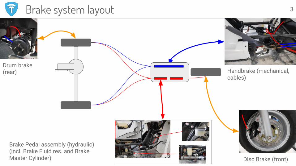
Handbrake (mechanical, cables)
Disc Brake (front)
Brake Pedal assembly (hydraulic) (incl. Brake Fluid res. and Brake Master Cylinder)
Brake system layout
Drum brake (rear)
3
Contents:
● Rear suspension overview● Rear axle and differential
○ Overview○ Maintenance○ Replacement
Useful information and recommendations:
● Use 800ml of oil in the differential, recommended type Tranself B 80W90.
● Always thoroughly clean the differential and its components before reassembly.
● Be sure to use correct spacer (there are similar, but different versions with different length and diameter)
● Check free wheel movement after installing differential components and/or motor
● Always re-torque wheel bolts after 100km.
Rear suspensionThings to look out for:
● Noise and vibrations coming from the rear axle while driving.
● Metal residue and dirt on the filler cap or in the differential oil.
● Oil leaks
Possible issues:
● Broken differential gears● Broken drive axle● Leaking differential seals● Work or leaking bearings● Worn suspension bushings
4
E
D
A
B
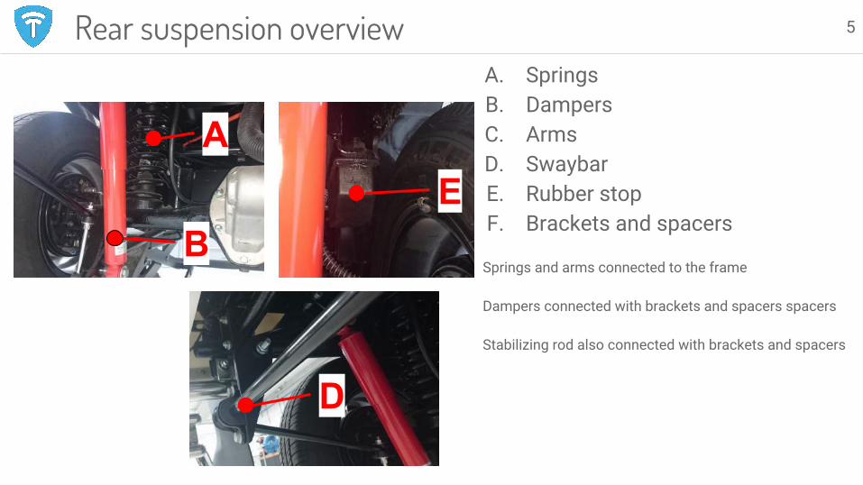
Rear suspension overviewA. SpringsB. DampersC. ArmsD. SwaybarE. Rubber stopF. Brackets and spacers
Springs and arms connected to the frame
Dampers connected with brackets and spacers spacers
Stabilizing rod also connected with brackets and spacers
5
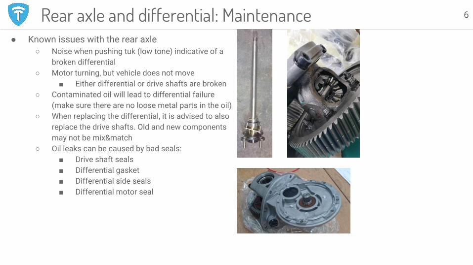
● Known issues with the rear axle○ Noise when pushing tuk (low tone) indicative of a
broken differential○ Motor turning, but vehicle does not move
■ Either differential or drive shafts are broken○ Contaminated oil will lead to differential failure
(make sure there are no loose metal parts in the oil)○ When replacing the differential, it is advised to also
replace the drive shafts. Old and new components may not be mix&match
○ Oil leaks can be caused by bad seals:■ Drive shaft seals■ Differential gasket■ Differential side seals■ Differential motor seal
Rear axle and differential: Maintenance 6

Differential removal and installation part 1
1. Disassemble drive shaftsa. Remove wheels and brake drums to reveal drive shaft. b. Unbolt the 4 M8 bolts from the back of the drum brake
anchor plate.c. Use an axle puller set to remove the axle
2. Remove the motora. Perform service power disconnect and disconnect the
main battery B- from the motor controller (see safety instruction section)
b. Open the motor cable enclosure and disconnect all cables and connectors. Remove the motor cable enclosure.
c. Unbolt 6 M6 hex bolts from the motor.d. Support the motor with a garage jack and slide it from
the drive axle (to the right).e. Installation is the reverse proceduref. Apply grease on the spline before installing the motorg. Torque values:
i. Motor flange M6: 14Nmii. Motor cable terminal: 12Nm
Rear axle and differential maintenance 7

Differential removal and installation part 2
3. Remove the draining plug (underside differential bell housing) and drain all differential oil, check the inside of the plug for metal debris (there is a magnet here). Lots of debris indicates excessive gear wear.
4. Unbolt all differential bolts and remove the differential. (Pre 2017 vehicles have axle structure that needs to be removed as well. If this structure is welded in place it needs to be cut away and reinstalled using a retrofit flange kit)
Installation:
1. Thoroughly clean the inside of the axle and all parts to remove all debris and dirt.
2. Clean the contact surface of differential and axle and put silicone gasket sealer paste on the flange and install the green gasket.
3. Fit new differential, use lock bonding material on the bolts and tighten the bolts with 14Nm. (TTF recommends to install new drive shafts whenever installing a new differential)
4. Fill the differential with 80ml Tranself B 80W90. 5. Reassemble all other parts.
Rear axle and differential maintenance 8
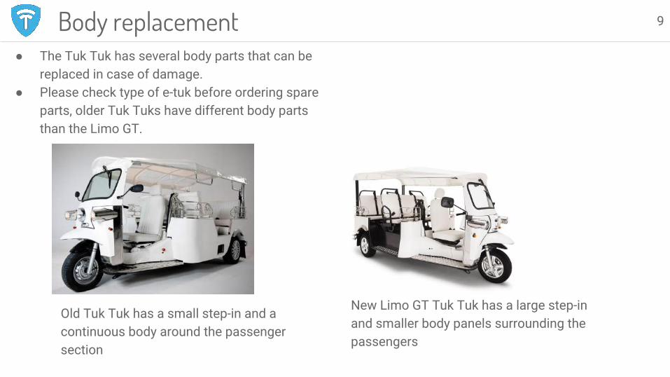
● The Tuk Tuk has several body parts that can be replaced in case of damage.
● Please check type of e-tuk before ordering spare parts, older Tuk Tuks have different body parts than the Limo GT.
Body replacement 9
Old Tuk Tuk has a small step-in and a continuous body around the passenger section
New Limo GT Tuk Tuk has a large step-in and smaller body panels surrounding the passengers

10
Electrical, hardware
Safe working on the electric drive train - work procedure 11
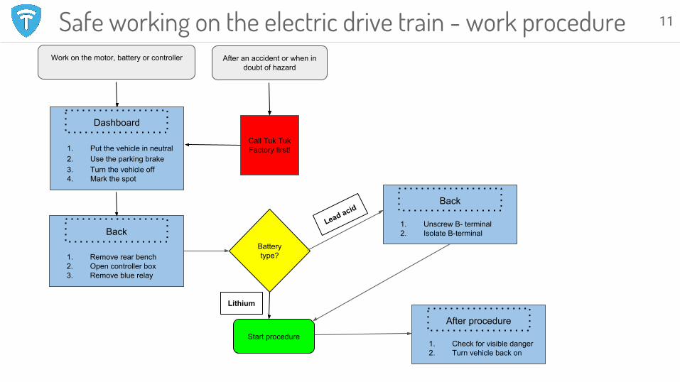
Work on the motor, battery or controller After an accident or when in doubt of hazard
Call Tuk Tuk Factory first!
Dashboard
1. Remove rear bench2. Open controller box3. Remove blue relay
Back
1. Put the vehicle in neutral2. Use the parking brake3. Turn the vehicle off4. Mark the spot
Dashboard
Battery type?
Start procedure1. Check for visible danger2. Turn vehicle back on
After procedure
Lithium
Lead acid
1. Unscrew B- terminal2. Isolate B-terminal
Back
Electric system: Starting sequence 12
12 V
DC-DC
15
Controller
DC-DCConverter
START
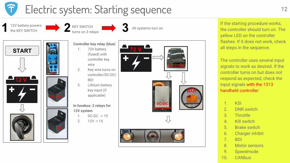
Electric system: Starting sequenceIf the starting procedure works, the controller should turn on. The yellow LED on the controller flashes. If it does not work, check all steps in the sequence.
The controller uses several input signals to work as desired. If the controller turns on but does not respond as expected, check the input signals with the 1313 handheld controller:
1. KSI2. DNR switch3. Throttle4. Kill switch5. Brake switch6. Charger inhibit7. BDI8. Motor sensors9. Speedmode
10. CANbus
1 2 312V battery powersthe KEY SWITCH
KEY SWITCHturns on 3 relays
All systems turn on
BDI
Controller key relay (blue)1. 72V battery
(fused) with controller key wire
2. Key wire turns on controller/DC-DC/BDI
3. Lithium battery key input (if applicable)
In fusebox: 2 relays for 12V system
1. DC-DC -> 15 2. 12V -> 15
72 V
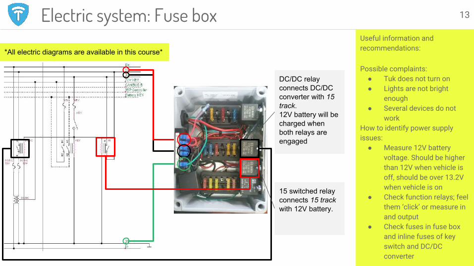
DC/DC relay connects DC/DC converter with 15 track. 12V battery will be charged when both relays are engaged
15 switched relay connects 15 track with 12V battery.
Useful information and recommendations:
Possible complaints:● Tuk does not turn on● Lights are not bright
enough● Several devices do not
workHow to identify power supply issues:
● Measure 12V battery voltage. Should be higher than 12V when vehicle is off, should be over 13.2V when vehicle is on
● Check function relays; feel them ‘click’ or measure in and output
● Check fuses in fuse box and inline fuses of key switch and DC/DC converter
Electric system: Fuse box
*All electric diagrams are available in this course*
13
CONTROLLER
35P
MAIN CONTACTOR
DC/DCCONVERTERKEY FUSE
KEY RELAYM
AIN
FU
SE
OPTO ADAPTER
DCDC FUSE
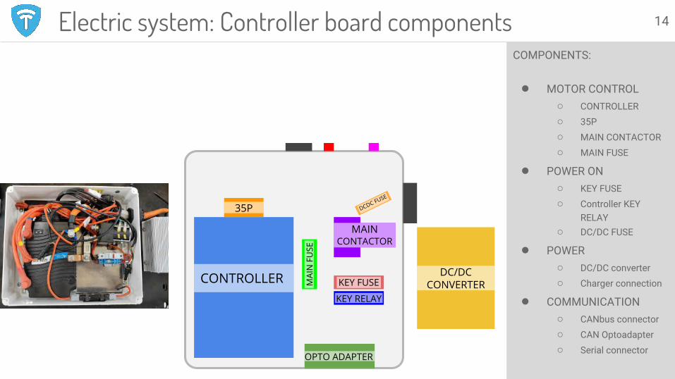
COMPONENTS:
● MOTOR CONTROL○ CONTROLLER○ 35P○ MAIN CONTACTOR○ MAIN FUSE
● POWER ON○ KEY FUSE○ Controller KEY
RELAY○ DC/DC FUSE
● POWER○ DC/DC converter○ Charger connection
● COMMUNICATION○ CANbus connector○ CAN Optoadapter○ Serial connector
Electric system: Controller board components 14
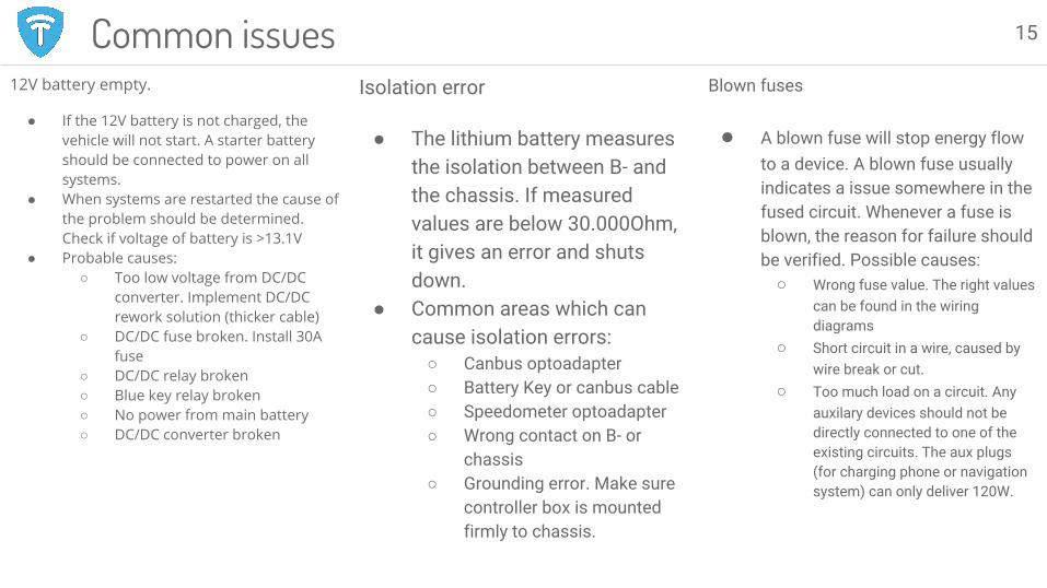
12V battery empty.
● If the 12V battery is not charged, the vehicle will not start. A starter battery should be connected to power on all systems.
● When systems are restarted the cause of the problem should be determined. Check if voltage of battery is >13.1V
● Probable causes:○ Too low voltage from DC/DC
converter. Implement DC/DC rework solution (thicker cable)
○ DC/DC fuse broken. Install 30A fuse
○ DC/DC relay broken○ Blue key relay broken○ No power from main battery○ DC/DC converter broken
Blown fuses
● A blown fuse will stop energy flow to a device. A blown fuse usually indicates a issue somewhere in the fused circuit. Whenever a fuse is blown, the reason for failure should be verified. Possible causes:
○ Wrong fuse value. The right values can be found in the wiring diagrams
○ Short circuit in a wire, caused by wire break or cut.
○ Too much load on a circuit. Any auxilary devices should not be directly connected to one of the existing circuits. The aux plugs (for charging phone or navigation system) can only deliver 120W.
15Common issuesIsolation error
● The lithium battery measures the isolation between B- and the chassis. If measured values are below 30.000Ohm, it gives an error and shuts down.
● Common areas which can cause isolation errors:
○ Canbus optoadapter○ Battery Key or canbus cable○ Speedometer optoadapter○ Wrong contact on B- or
chassis○ Grounding error. Make sure
controller box is mounted firmly to chassis.
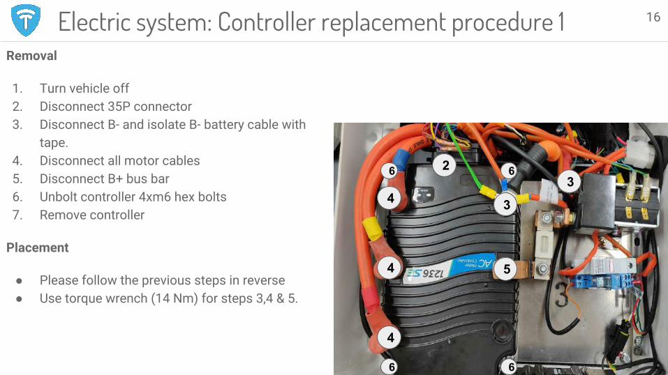
Electric system: Controller replacement procedure 1Removal
1. Turn vehicle off2. Disconnect 35P connector3. Disconnect B- and isolate B- battery cable with
tape.4. Disconnect all motor cables5. Disconnect B+ bus bar6. Unbolt controller 4xm6 hex bolts7. Remove controller
Placement
● Please follow the previous steps in reverse● Use torque wrench (14 Nm) for steps 3,4 & 5.
16
2
3
34
4
4
6
5
6
66

Electric system: Controller replacement procedure 2Installation
1. Clean surfaces controller and aluminium plate
2. Apply heat conductive paste3. Position controller on alu plate
and bolt down. 4. Connect all cables. Fasten bolts
with 14Nm5. Connect 35pin connector
Place controller and thermal paste on clean desk. Flip controller and clean surface.
Apply thermal paste in thin lines. Spread with back of tube, evenly over the whole surface.
17
Source: Curtis
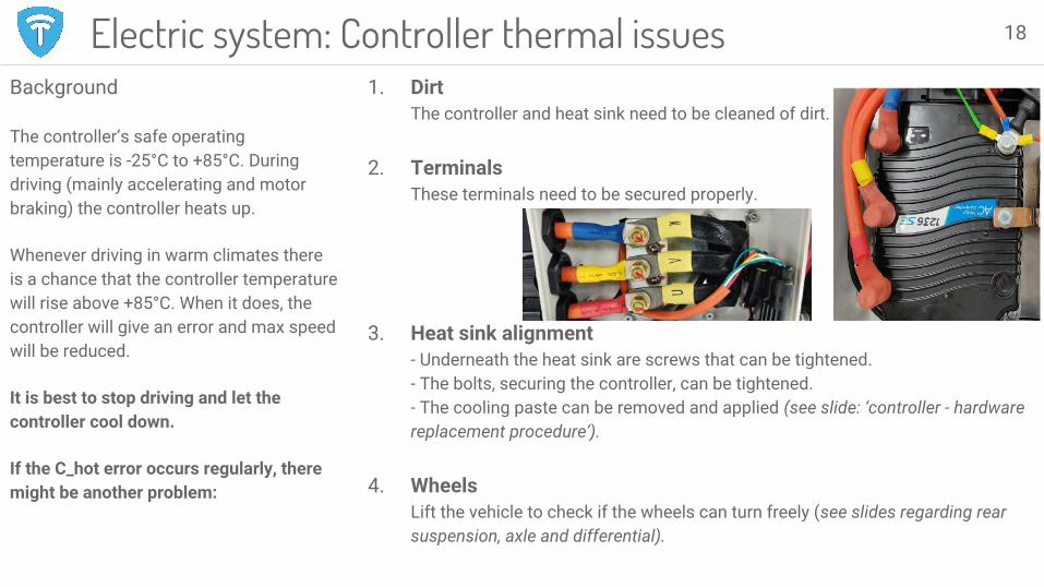
Electric system: Controller thermal issuesBackground
The controller’s safe operating temperature is -25°C to +85°C. During driving (mainly accelerating and motor braking) the controller heats up.
Whenever driving in warm climates there is a chance that the controller temperature will rise above +85°C. When it does, the controller will give an error and max speed will be reduced.
It is best to stop driving and let the controller cool down.
If the C_hot error occurs regularly, there might be another problem:
1. DirtThe controller and heat sink need to be cleaned of dirt.
2. TerminalsThese terminals need to be secured properly.
3. Heat sink alignment- Underneath the heat sink are screws that can be tightened.- The bolts, securing the controller, can be tightened.- The cooling paste can be removed and applied (see slide: ‘controller - hardware replacement procedure’).
4. WheelsLift the vehicle to check if the wheels can turn freely (see slides regarding rear suspension, axle and differential).
18
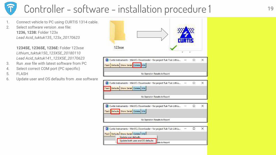
1. Connect vehicle to PC using CURTIS 1314 cable.2. Select software version .exe file:
1236, 1238: Folder 123x Lead Acid_tuktuk135_123x_20170623
1234SE, 1236SE, 1236E: Folder 123xseLithium_tuktuk150_123XSE_20180110Lead Acid_tuktuk141_123XSE_20170623
3. Run .exe file with latest software from PC4. Select correct COM port (PC specific)5. FLASH6. Update user and OS defaults from .exe software
19Controller - software - installation procedure 1
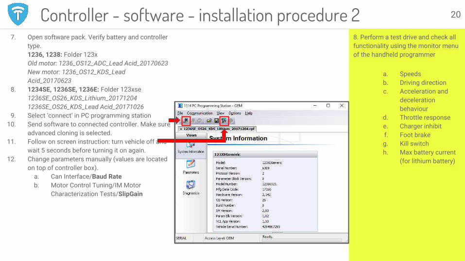
8. Perform a test drive and check all functionality using the monitor menu of the handheld programmer
a. Speedsb. Driving directionc. Acceleration and
deceleration behaviour
d. Throttle responsee. Charger inhibitf. Foot brakeg. Kill switchh. Max battery current
(for lithium battery)
7. Open software pack. Verify battery and controller type.1236, 1238: Folder 123x Old motor: 1236_OS12_ADC_Lead Acid_20170623New motor: 1236_OS12_KDS_Lead Acid_20170623
8. 1234SE, 1236SE, 1236E: Folder 123xse1236SE_OS26_KDS_Lithium_201712041236SE_OS26_KDS_Lead Acid_20171026
9. Select ‘connect’ in PC programming station10. Send software to connected controller. Make sure
advanced cloning is selected.11. Follow on screen instruction: turn vehicle off and
wait 5 seconds before turning it on again.12. Change parameters manually (values are located
on top of controller box).a. Can Interface/Baud Rateb. Motor Control Tuning/IM Motor
Characterization Tests/SlipGain
20Controller - software - installation procedure 2

Common controller errors● Error 47/Put 0: Correct starting procedure has not
been followed. Put DNR back in N, close throttle to clear error. If this does not help, verify inputs (next slide).
● Error 23: Usually an empty battery. Recharge. If this does not help, check battery health.
● Error 12, 36, 73: Encoder fault. Clean encoder and check encoder connection.
● Error 38: Main contactor did not close. Check and clean connections of main contactor and main fuse. Check battery health.
● Error 22/C hot: Controller gets hot. See Slide 39●
21

Browsing useful menus
1. Parameters. To check or change controller settings.
2. Monitor. To check controller in and outputs.
3. Diagnostics. To see current and historic system errors.
4. Programming. To clone full controller parameter settings.
Signal Input ResponseThrottle Throttle POT 0-1V with throttle closed. 4,5-5V with throttle openBrake pedal Brake command 0% when released, 100% when pressed (lightly)Kill switch Switch 3 On when on, off when offBrake pedal Switch 4 Value should change when pressedCharger inhibit* Switch 5 Value should change when charger is plugged inDNR - Drive Switch 7 Only on when DDNR - Reverse Switch 8 Only on when R
Handheld programmer 22
Troubleshooting
All controller inputs can be read in the 1313 menu: MONITOR/INPUTS. You should verify if all controls respond as in table below.
Programming
Use programming menu to upload a .cpf file to the controller.
Speedometer calibration
1. Measure the vehicle speed using GPS\2. Write down the speed on the
speedometer and the GPS speed3. Change the following value:
Programming/TukTuk/Speedometer: Speedometer Frequency Max Speed
4. Change using the following formula: Speed GPS / Speed on speedometer x Speedometer Frequency Max Speed = New Speedometer Frequency max speed.
Make sure to use a suitable file, matching the VCL version number and OS version number, controller type, motor type and battery type.

Installation of USB device
1. On your computer, go to ‘Control Panel’ -> ‘Device Manager’ -> ‘Universal Serial Bus (USB) Controller’ -> ‘ZLG USBCAN’
2. Right click ‘Update Driver Software’ -> ‘Browse my Computer’ -> Go to ‘Dynavolt/Drivers’ folder
3. Install driver
Lithium battery - software - installation 23
1
2 3
4

Communication
1. Plug CANUSB-adapter in controller box and PC
2. Open GDTS-folder on provided USB-stick
3. “Start GTDS-Car-Monitor.exe”
Lithium battery: Software 24
1
2
Interface
1. HomescreenClick GTDS logo to connect.
2. BatteryCell voltage & temperature
3. BMS‘FaultInformation’ -> FaultLevel’Correlates with ‘Berr’ on BDI
3

Motor hardware - TroubleshootingTo clean the motor, pressurized air should be pushed into the vents while using a vacuum cleaner on the opposite side of the motor to help direct the debris out of the motor
There could be a problem with the encoder when you receive errors 12, 13, 25, 36 or 37.
To check encoder function, check 'MOTOR SPEED A' and 'MOTOR SPEED B' in MONITOR/INPUTS. They should both give similar values.
Check the wiring and clean encoder.
1. Remove2. Clean the encoder 3. Install encoder
25

BATTERIES
26
27
Session information:
● Duration: 60 minutes● Presented by:
Thomas/Marijn● Training material:
○ Voltage table○ Software package○ CAN adapter
● Objectives: Learn the various battery components that can be present in the Tuk Tuk; 12 volt, Lead Acid or Lithium. How is the battery tray constructed. What kind of service and maintenance is required. What kind of errors can be expected.
Content:
● Lead acid vs lithium● Lead acid battery
○ Installation○ Maintenance○ Troubleshooting
● Lithium battery○ Installation○ Maintenance○ Troubleshooting
● Charging● Battery range
Practical session:
● Install battery cable● Install filling system● Check battery quality
○ Check water level○ Check voltage○ Check water quality
● Connect battery cables to controller
Batteries
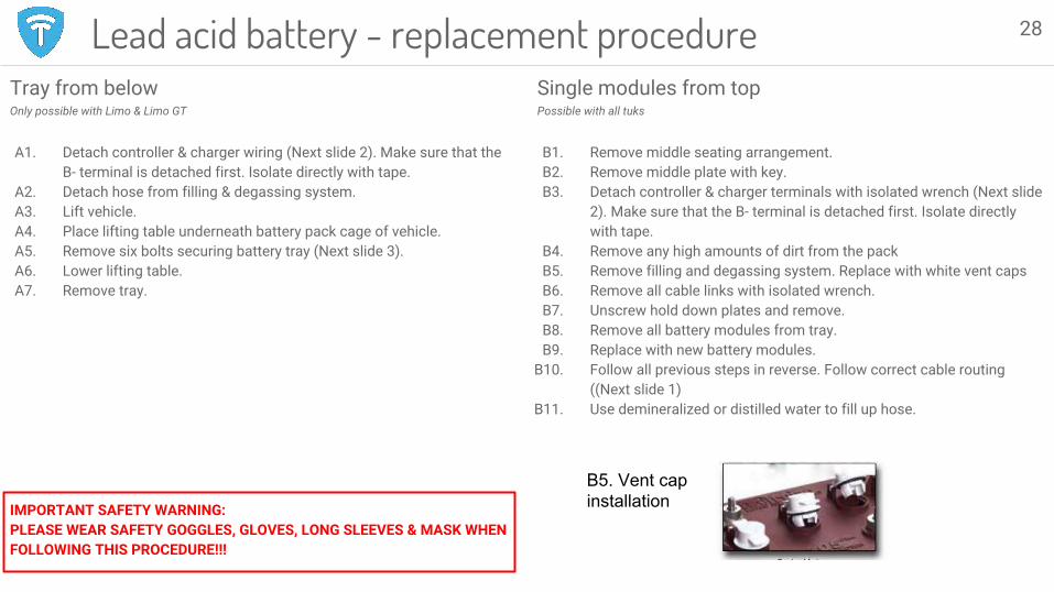
Tray from belowOnly possible with Limo & Limo GT
A1. Detach controller & charger wiring (Next slide 2). Make sure that the B- terminal is detached first. Isolate directly with tape.
A2. Detach hose from filling & degassing system.A3. Lift vehicle.A4. Place lifting table underneath battery pack cage of vehicle.A5. Remove six bolts securing battery tray (Next slide 3).A6. Lower lifting table.A7. Remove tray.
IMPORTANT SAFETY WARNING:PLEASE WEAR SAFETY GOGGLES, GLOVES, LONG SLEEVES & MASK WHEN FOLLOWING THIS PROCEDURE!!!
Lead acid battery - replacement procedureSingle modules from topPossible with all tuks
B1. Remove middle seating arrangement.B2. Remove middle plate with key.B3. Detach controller & charger terminals with isolated wrench (Next slide
2). Make sure that the B- terminal is detached first. Isolate directly with tape.
B4. Remove any high amounts of dirt from the packB5. Remove filling and degassing system. Replace with white vent capsB6. Remove all cable links with isolated wrench. B7. Unscrew hold down plates and remove.B8. Remove all battery modules from tray.B9. Replace with new battery modules.
B10. Follow all previous steps in reverse. Follow correct cable routing ((Next slide 1)
B11. Use demineralized or distilled water to fill up hose.
28
B5. Vent cap installation
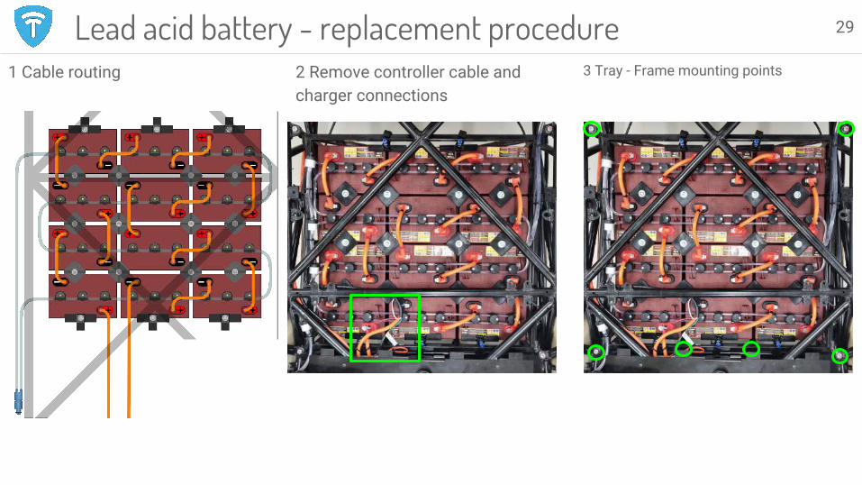
1 Cable routing 2 Remove controller cable and charger connections
3 Tray - Frame mounting points
Lead acid battery - replacement procedure 29

● Batteries are over 30kg, lifting and moving the batteries should be done using the dedicated Trojan lifting strap
● Read the acid and electrical safety instructions in this manual
Whenever one battery module needs replacing, TTF recommends to replace all modules. One fresh module can degrade quickly if the rest of the pack is in poor health.
The battery pack can be replaced by lifting the cells out the vehicle one by one. When installing new cells, please follow the cable and module orientation in image below.
For EUT terminal cable installation follow the next steps:
1. The cable needs to be installed on the outer side of the terminal. The inner side is smaller and suitable for the squared nut.
2. Install the battery cable on the EUT terminal according to the images below.
3. Do a visual check if the surfaces of the terminal and cable fully touch
4. Use a torque wrench to tighten the nut on 14Nm.
5. Apply battery terminal protection spray to protect the terminal from oxidation and dirt.
6. Use the copper bus bars for charger and controller cable connections (image)
Battery modules need to be securely fastened in the battery tray. Make sure to use the battery hold downs on all 18 locations. There are three types of hold downs.
30Lead acid module installation
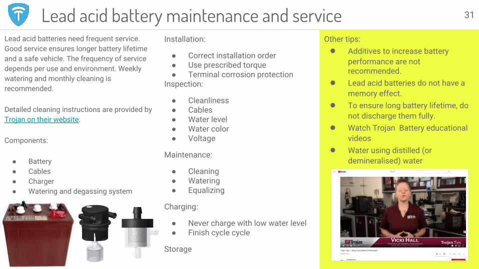
Lead acid batteries need frequent service. Good service ensures longer battery lifetime and a safe vehicle. The frequency of service depends per use and environment. Weekly watering and monthly cleaning is recommended.
Detailed cleaning instructions are provided by Trojan on their website.
Components:
● Battery● Cables● Charger● Watering and degassing system
Installation:
● Correct installation order● Use prescribed torque● Terminal corrosion protection
Inspection:
● Cleanliness● Cables● Water level● Water color● Voltage
Maintenance:
● Cleaning● Watering● Equalizing
Charging:
● Never charge with low water level● Finish cycle cycle
Storage
Other tips: ● Additives to increase battery
performance are not recommended.
● Lead acid batteries do not have a memory effect.
● To ensure long battery lifetime, do not discharge them fully.
● Watch Trojan Battery educational videos
● Water using distilled (or demineralised) water
31Lead acid battery maintenance and service

Range is affected by:
● Battery quality● Vehicle load● Terrain● Climate● Driving style● Powertrain efficiency
Battery quality for lead acid batteries is affected by:
● Charge/discharge cycles○ Number of cycles○ DoD○ Unfinished charge cycles
● Good battery cleanliness and maintenance
● Low water level● Power cable and terminal quality
Battery quality is checked after a full charge:
1. Battery voltage check2. Water weight check3. Water color check
1. Voltage needs to be the same per battery. If voltage varies an equalization charge should be performed*
2. Water weight needs to be the same per cell. If weight varies >0.030 an equalization charge should be performed*
3. If water is brown, the lead plates have degraded and batteries cannot be restored. A milky water color is caused by sulfation. Equalization can prevent further damage. Use hydrometer to check water color.
Equalization is done after a full charge cycle. Simply unplug the charge and replug it to start the process. Equalization charge can take about 2 hours and can be repeated if effect is not sufficient.
*Voltage and water weight values can be found in the user manual.
32Lead acid battery: Troubleshooting
Installation
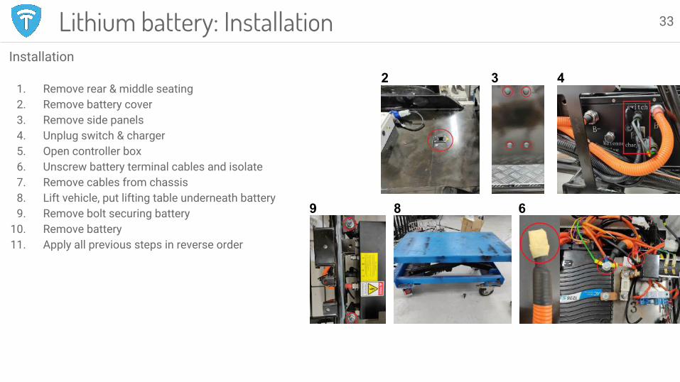
1. Remove rear & middle seating2. Remove battery cover3. Remove side panels4. Unplug switch & charger5. Open controller box6. Unscrew battery terminal cables and isolate7. Remove cables from chassis8. Lift vehicle, put lifting table underneath battery9. Remove bolt securing battery
10. Remove battery11. Apply all previous steps in reverse order
2 3 4
9 8 6
Lithium battery: Installation 33
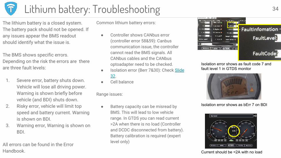
The lithium battery is a closed system. The battery pack should not be opened. If any issues appear the BMS readout should identify what the issue is.
The BMS shows specific errors. Depending on the risk the errors are there are three fault levels:
1. Severe error, battery shuts down. Vehicle will lose all driving power. Warning is shown briefly before vehicle (and BDI) shuts down.
2. Risky error, vehicle will limit top speed and battery current. Warning is shown on BDI.
3. Warning error, Warning is shown on BDI.
All errors can be found in the Error Handbook.
Lithium battery: TroubleshootingCommon lithium battery errors:
● Controller shows CANbus error (controller error 58&59): Canbus communication issue, the controller cannot read the BMS signals. All CANbus cables and the CANbus optoadapter need to be checked.
● Isolation error (Berr 7&30): Check Slide 32.
● Cell balance
Range issues:
● Battery capacity can be misread by BMS. This will lead to low vehicle range. In GTDS you can read current >2A when there is no load (Controller and DCDC disconnected from battery). Battery calibration is required (expert level only)
34
Isolation error shows as fault code 7 and fault level 1 in GTDS monitor
Isolation error shows as bErr 7 on BDI
Current should be <2A with no load
General recommendations● Always make sure to have a clean and
well maintained battery● Always fully unwind power reels to
prevent them from heating up and burn● Use charging equipment that is suited
for high power (1kW for lead acid, 2,5kW for lithium
● Regularly check charging cables and charging cable connections
● Store batteries between 0-40 °C● Never charge a battery when ambient
temperature is below 0°C
Lead acid● Charging develops H2 gas, charge in well
ventilated areasStorage
● Lead acid batteries have a self discharge and drain over time
● Charger jumps to storage mode when finished, it will restart after several days
Troubleshooting● Charger gives error code (count red
blinking light): Check the error handbook.
● Battery voltage is too low: Use a special service charger (Algorithm 1 V1.13) to raise pack voltage above 60V.
● Charger stops after some time: Check for charger errors, check AC power supply. (power reels have heat sensors and load protection.
Charging & storage 35
Lithium● Lithium charger does not show charging
state or progress. Turn vehicle on and view BDI for SOC
● Disconnect charger after charge cycleStorage
● Charge a battery before storage● Complete self discharge will damage the
battery beyond repair:○ A full lithium battery will self
discharge within 6 months○ An empty lithium battery will
self-discharge within 2 weeks.Troubleshooting
● Check if charger is recognised on the CANbus, use GTDS
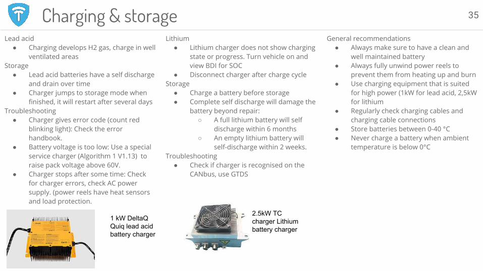
1 kW DeltaQ Quiq lead acid battery charger
2.5kW TC charger Lithium battery charger