servo education nava study guide - philippe le … introduction nava – neurally adjusted...
TRANSCRIPT

SERVO EducationNAVA STUDY GUIDE


NAVA STUDY GUIDEEnglish version1.6
3
| Table of Contents |
TABLE OF CONTENTS
5|Introduction117|NAVA Workflow229|Mode description341|Troubleshooting445|Alarms549|References for NAVA Study Guide6
4 NAVA STUDY GUIDEEnglish version
1.6
| Table of Contents |
1 INTRODUCTION
TABLE OF CONTENTS
6|Introduction1
7|Neuroventilatory coupling1.19|Respiratory control1.2
11|NAVA accessories1.312|Edi Catheter1.414|Edi Module1.5
NAVA STUDY GUIDEEnglish version1.6
5
| Introduction | 1 |
1 INTRODUCTION
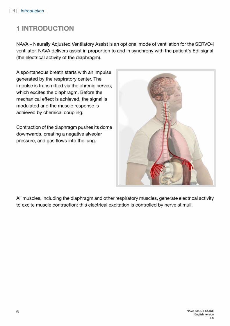
NAVA – Neurally Adjusted Ventilatory Assist is an optional mode of ventilation for the SERVO-iventilator. NAVA delivers assist in proportion to and in synchrony with the patient’s Edi signal(the electrical activity of the diaphragm).
A spontaneous breath starts with an impulsegenerated by the respiratory center. Theimpulse is transmitted via the phrenic nerves,which excites the diaphragm. Before themechanical effect is achieved, the signal ismodulated and the muscle response isachieved by chemical coupling.
Contraction of the diaphragm pushes its domedownwards, creating a negative alveolarpressure, and gas flows into the lung.
All muscles, including the diaphragm and other respiratory muscles, generate electrical activityto excite muscle contraction: this electrical excitation is controlled by nerve stimuli.
6 NAVA STUDY GUIDEEnglish version
1.6
| 1 | Introduction |
1.1 NEUROVENTILATORY COUPLING
ml
μV
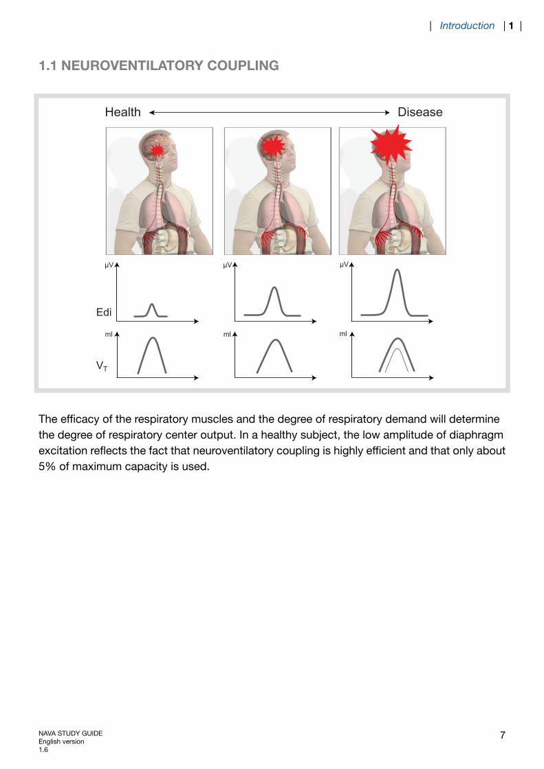
Health Disease
Edi
V T
ml
μV
ml
μV
The efficacy of the respiratory muscles and the degree of respiratory demand will determinethe degree of respiratory center output. In a healthy subject, the low amplitude of diaphragmexcitation reflects the fact that neuroventilatory coupling is highly efficient and that only about5% of maximum capacity is used.
NAVA STUDY GUIDEEnglish version1.6
7
| Introduction | 1 |

In disease, muscle performance may not be up to expectation, leading to an increased outputfrom the respiratory center with the aim of recruiting additional motor units in the diaphragm.
In this example, the increased signal seen inCOPD and post-polio patients thus reflectsthe fact that a larger part of the muscularreserve is used. Only 5-8% of maximumcapacity is used in healthy subjects, while upto 40% is used in COPD patients.
If the diaphragm becomes weaker and/or the inspiratory loadincreases, the diaphragm´s electrical activation must increase tomaintain a given volume. (Adapted from Sinderby et al JAP 1998)
The electrical activity of the diaphragm (Edi) is measured in μV (micro volt). 1 μV = 10-6V, thus1,000,000 μV = 1V.
8 NAVA STUDY GUIDEEnglish version
1.6
| 1 | Introduction |
1.2 RESPIRATORY CONTROL
There are three important components in mechanical ventilation:
1. The timing with which breaths are delivered i.e. the frequency and inspiratory time forassist delivery.
2. The magnitude of the delivered breaths, i.e. the pressure or volume needed to ventilatethe lungs.
3. The magnitude of pressure on expiration, which prevents the lungs from derecruitingbetween inspirations, i.e. the required PEEP level.
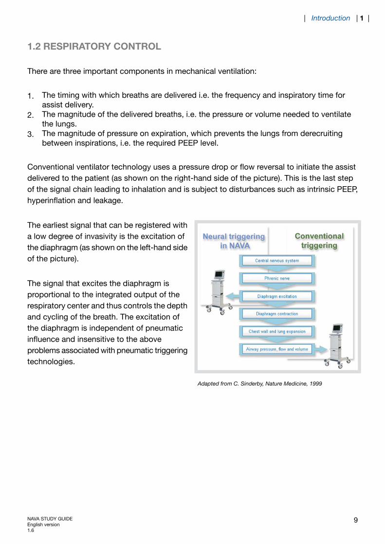
Conventional ventilator technology uses a pressure drop or flow reversal to initiate the assistdelivered to the patient (as shown on the right-hand side of the picture). This is the last stepof the signal chain leading to inhalation and is subject to disturbances such as intrinsic PEEP,hyperinflation and leakage.
The earliest signal that can be registered witha low degree of invasivity is the excitation ofthe diaphragm (as shown on the left-hand sideof the picture).
The signal that excites the diaphragm isproportional to the integrated output of therespiratory center and thus controls the depthand cycling of the breath. The excitation ofthe diaphragm is independent of pneumaticinfluence and insensitive to the aboveproblems associated with pneumatic triggeringtechnologies.
Adapted from C. Sinderby, Nature Medicine, 1999
NAVA STUDY GUIDEEnglish version1.6
9
| Introduction | 1 |
By following diaphragm excitation and adjusting the support level in synchrony with the riseand fall of the electrical discharge, the ventilator and the diaphragm will work with the samesignal input. In effect, this allows the ventilator to function as an extra muscle, unloading extrarespiratory work induced by the disease process.
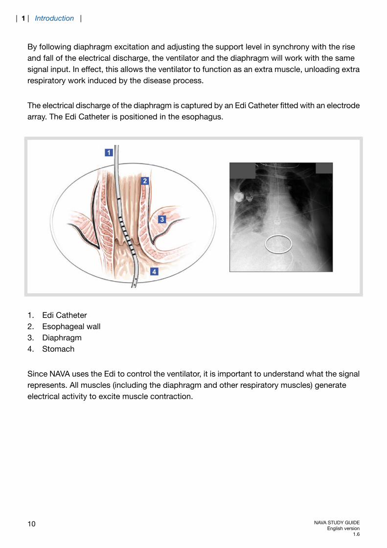
The electrical discharge of the diaphragm is captured by an Edi Catheter fitted with an electrodearray. The Edi Catheter is positioned in the esophagus.
1. Edi Catheter2. Esophageal wall3. Diaphragm4. Stomach
Since NAVA uses the Edi to control the ventilator, it is important to understand what the signalrepresents. All muscles (including the diaphragm and other respiratory muscles) generateelectrical activity to excite muscle contraction.
10 NAVA STUDY GUIDEEnglish version
1.6
| 1 | Introduction |
The electrical excitation is controlled by nerve stimulus and controlled in magnitude by adjustingthe stimulation frequency (rate coding) or the number of nerves sending the stimulus (nervefiber recruitment). Both rate coding and nerve fiber recruitment will be transmitted into musclefiber motor unit action potentials which will be summed up both in time and space to producethe intensity of electrical activity measured in the muscle, in this case the Edi. By means of theEdi signal, NAVA delivers pressure in response to the patient’s respiratory drive.
To reduce the influence of external noise, the measurement of muscle electrical activity isperformed by bipolar differential recordings, where the signal difference between two singleelectrodes is measured.
Patients with chronic respiratory insufficiency may demonstrate signals 5-7 times stronger tocompensate for this insufficiency. Due to the differential recording and low signal amplitude,measurement of Edi is sensitive to electrode filtering, external noise, and cross-talk from othermuscles, e.g. the heart which produces electrical amplitudes about 10-100 times that of thediaphragm. Since the Edi must always be present to initiate a contraction of the diaphragm,it should however always be possible to record the signal in healthy subjects.
1.3 NAVA ACCESSORIES
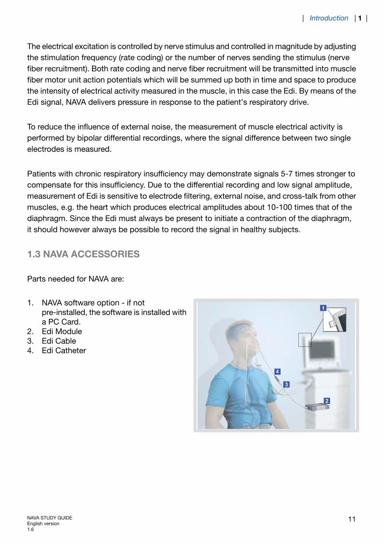
Parts needed for NAVA are:
1. NAVA software option - if notpre-installed, the software is installed witha PC Card.
2. Edi Module3. Edi Cable4. Edi Catheter
NAVA STUDY GUIDEEnglish version1.6
11
| Introduction | 1 |
1.4 EDI CATHETER
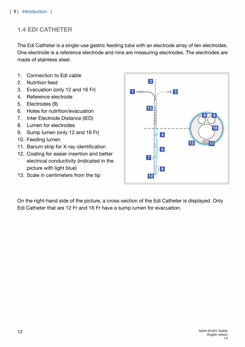
The Edi Catheter is a single-use gastric feeding tube with an electrode array of ten electrodes.One electrode is a reference electrode and nine are measuring electrodes. The electrodes aremade of stainless steel.
8075
7065
6055
501
2
3
5
6
7
8 9
10
1112
13
12
4
1. Connection to Edi cable2. Nutrition feed3. Evacuation (only 12 and 16 Fr)4. Reference electrode5. Electrodes (9)6. Holes for nutrition/evacuation7. Inter Electrode Distance (IED)8. Lumen for electrodes9. Sump lumen (only 12 and 16 Fr)10. Feeding lumen11. Barium strip for X-ray identification12. Coating for easier insertion and better
electrical conductivity (indicated in thepicture with light blue)
13. Scale in centimeters from the tip
On the right-hand side of the picture, a cross-section of the Edi Catheter is displayed. OnlyEdi Catheter that are 12 Fr and 16 Fr have a sump lumen for evacuation.
12 NAVA STUDY GUIDEEnglish version
1.6
| 1 | Introduction |
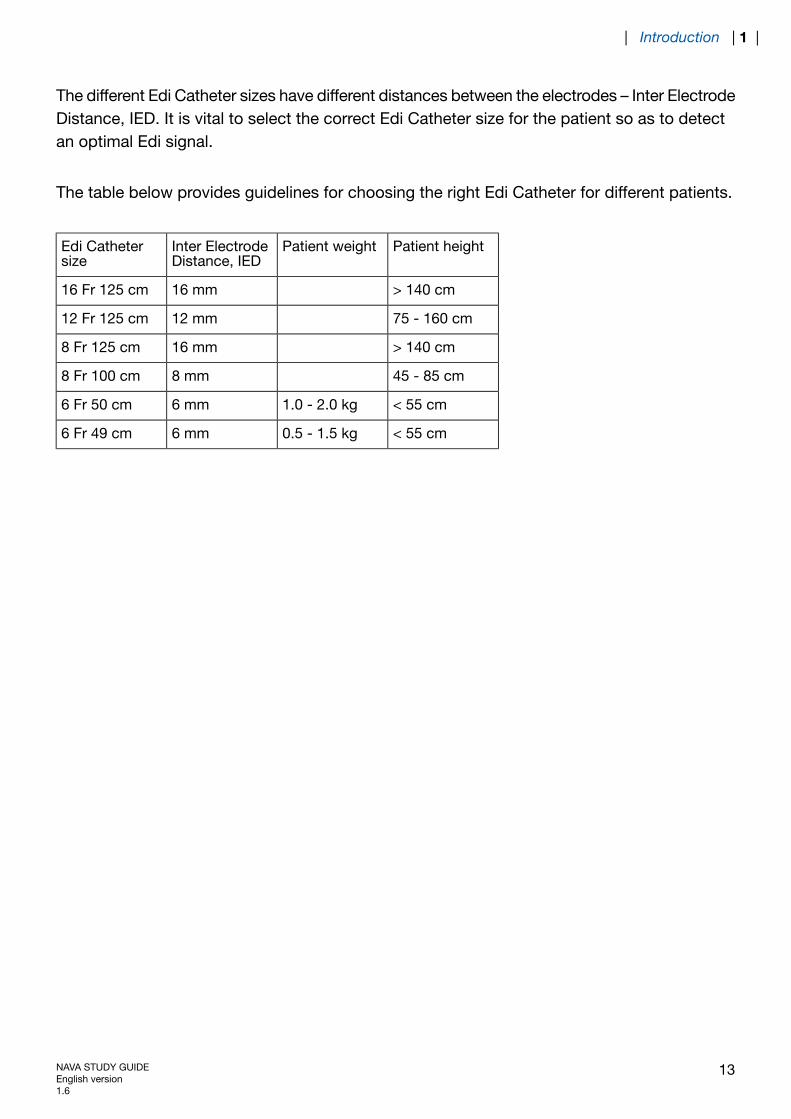
The different Edi Catheter sizes have different distances between the electrodes – Inter ElectrodeDistance, IED. It is vital to select the correct Edi Catheter size for the patient so as to detectan optimal Edi signal.
The table below provides guidelines for choosing the right Edi Catheter for different patients.
Patient heightPatient weightInter ElectrodeDistance, IED
Edi Cathetersize
> 140 cm16 mm16 Fr 125 cm
75 - 160 cm12 mm12 Fr 125 cm
> 140 cm16 mm8 Fr 125 cm
45 - 85 cm8 mm8 Fr 100 cm
< 55 cm1.0 - 2.0 kg6 mm6 Fr 50 cm
< 55 cm0.5 - 1.5 kg6 mm6 Fr 49 cm
NAVA STUDY GUIDEEnglish version1.6
13
| Introduction | 1 |
1.5 EDI MODULE
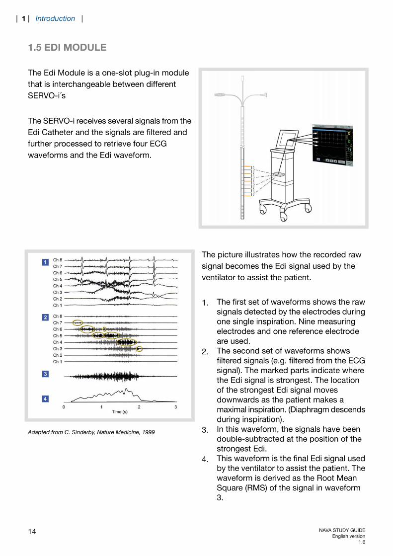
The Edi Module is a one-slot plug-in modulethat is interchangeable between differentSERVO-i´s
The SERVO-i receives several signals from theEdi Catheter and the signals are filtered andfurther processed to retrieve four ECGwaveforms and the Edi waveform.
The picture illustrates how the recorded rawsignal becomes the Edi signal used by theventilator to assist the patient.
1. The first set of waveforms shows the rawsignals detected by the electrodes duringone single inspiration. Nine measuringelectrodes and one reference electrodeare used.
2. The second set of waveforms showsfiltered signals (e.g. filtered from the ECGsignal). The marked parts indicate wherethe Edi signal is strongest. The locationof the strongest Edi signal movesdownwards as the patient makes amaximal inspiration. (Diaphragm descendsduring inspiration).
3. In this waveform, the signals have beendouble-subtracted at the position of thestrongest Edi.
4. This waveform is the final Edi signal usedby the ventilator to assist the patient. Thewaveform is derived as the Root MeanSquare (RMS) of the signal in waveform3.
Adapted from C. Sinderby, Nature Medicine, 1999
14 NAVA STUDY GUIDEEnglish version
1.6
| 1 | Introduction |

When NAVA is installed, the Edi signal is shown as a waveform on the SERVO-i User Interfacein all modes of ventilation as well as in stand-by mode, i.e. in the positioning window.
The Edi peak and Edi min are available as numerical values.
Edi peak – the highest Edi value during one breath cycleEdi min – the lowest Edi value during one breath cycle.
NAVA STUDY GUIDEEnglish version1.6
15
| Introduction | 1 |

16 NAVA STUDY GUIDEEnglish version
1.6
| 1 | Introduction |
2 NAVA WORKFLOW
TABLE OF CONTENTS
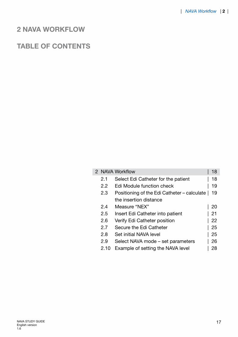
18|NAVA Workflow2
18|Select Edi Catheter for the patient2.119|Edi Module function check2.219|Positioning of the Edi Catheter – calculate
the insertion distance2.3
20|Measure “NEX”2.421|Insert Edi Catheter into patient2.522|Verify Edi Catheter position2.625|Secure the Edi Catheter2.725|Set initial NAVA level2.826|Select NAVA mode – set parameters2.928|Example of setting the NAVA level2.10
NAVA STUDY GUIDEEnglish version1.6
17
| NAVA Workflow | 2 |

2 NAVA WORKFLOW
Note: Refer to the User’s Manual for all safety related details.
The list describes the work flow, which will be further described in the sections below.
Select Edi Catheter for the patient.Insert Edi Module into SERVO-i.Connect Edi Cable to Edi Module.Perform Edi Module function check.Measure NEX and calculate the insertion distance Y for the Edi Catheter.Dip the Edi Catheter in water and insert it into patient.Connect the Edi Catheter to the Edi Cable.Position the Edi Catheter by using the positioning window.Set initial NAVA level.Select NAVA mode – set parameters and backup.Ventilate patient with NAVA.
The Edi signal can be displayed in all ventilatory modes.
2.1 SELECT EDI CATHETER FOR THE PATIENT
Patient heightPatient weightInter ElectrodeDistance, IED
Edi Cathetersize
> 140 cm16 mm16 Fr 125 cm
75 - 160 cm12 mm12 Fr 125 cm
> 140 cm16 mm8 Fr 125 cm
45 - 85 cm8 mm8 Fr 100 cm
< 55 cm1.0 - 2.0 kg6 mm6 Fr 50 cm
< 55 cm0.5 - 1.5 kg6 mm6 Fr 49 cm
18 NAVA STUDY GUIDEEnglish version
1.6
| 2 | NAVA Workflow |
2.2 EDI MODULE FUNCTION CHECK
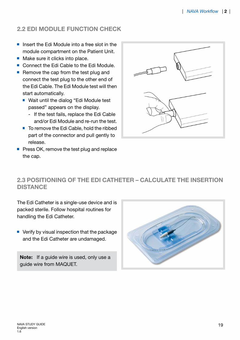
Insert the Edi Module into a free slot in themodule compartment on the Patient Unit.Make sure it clicks into place.Connect the Edi Cable to the Edi Module.Remove the cap from the test plug andconnect the test plug to the other end ofthe Edi Cable. The Edi Module test will thenstart automatically.
Wait until the dialog “Edi Module testpassed” appears on the display.- If the test fails, replace the Edi Cable
and/or Edi Module and re-run the test.To remove the Edi Cable, hold the ribbedpart of the connector and pull gently torelease.
Press OK, remove the test plug and replacethe cap.
2.3 POSITIONING OF THE EDI CATHETER – CALCULATE THE INSERTIONDISTANCE
The Edi Catheter is a single-use device and ispacked sterile. Follow hospital routines forhandling the Edi Catheter.
Verify by visual inspection that the packageand the Edi Catheter are undamaged.
Note: If a guide wire is used, only use aguide wire from MAQUET.
NAVA STUDY GUIDEEnglish version1.6
19
| NAVA Workflow | 2 |
2.4 MEASURE “NEX”
1
2
3
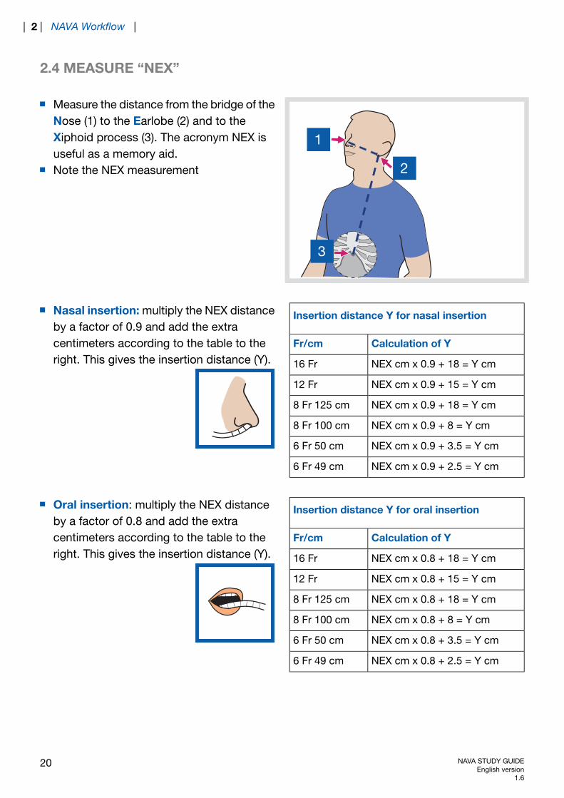
Measure the distance from the bridge of theNose (1) to the Earlobe (2) and to theXiphoid process (3). The acronym NEX isuseful as a memory aid.Note the NEX measurement
Insertion distance Y for nasal insertion
Calculation of YFr/cm
NEX cm x 0.9 + 18 = Y cm16 Fr
NEX cm x 0.9 + 15 = Y cm12 Fr
NEX cm x 0.9 + 18 = Y cm8 Fr 125 cm
NEX cm x 0.9 + 8 = Y cm8 Fr 100 cm
NEX cm x 0.9 + 3.5 = Y cm6 Fr 50 cm
NEX cm x 0.9 + 2.5 = Y cm6 Fr 49 cm
Nasal insertion: multiply the NEX distanceby a factor of 0.9 and add the extracentimeters according to the table to theright. This gives the insertion distance (Y).
Insertion distance Y for oral insertion
Calculation of YFr/cm
NEX cm x 0.8 + 18 = Y cm16 Fr
NEX cm x 0.8 + 15 = Y cm12 Fr
NEX cm x 0.8 + 18 = Y cm8 Fr 125 cm
NEX cm x 0.8 + 8 = Y cm8 Fr 100 cm
NEX cm x 0.8 + 3.5 = Y cm6 Fr 50 cm
NEX cm x 0.8 + 2.5 = Y cm6 Fr 49 cm
Oral insertion: multiply the NEX distanceby a factor of 0.8 and add the extracentimeters according to the table to theright. This gives the insertion distance (Y).
20 NAVA STUDY GUIDEEnglish version
1.6
| 2 | NAVA Workflow |

2.5 INSERT EDI CATHETER INTO PATIENT
Dip the Edi Catheter in water for a few seconds to activatethe coating for easier insertion and better electricalconductivity.
IMPORTANT: Do not apply any other substance thanwater to the Edi Catheter. Other substances (lubricants,gels or any other solvents) might destroy the coatingand disturb the contact with the electrodes.
Insert the Edi Catheter through the nostril or through the mouth until the calculated insertiondistance (Y) is reached.
NAVA STUDY GUIDEEnglish version1.6
21
| NAVA Workflow | 2 |
2.6 VERIFY EDI CATHETER POSITION
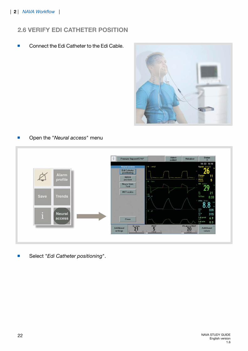
Connect the Edi Catheter to the Edi Cable.
Open the "Neural access" menu
Select "Edi Catheter positioning".
22 NAVA STUDY GUIDEEnglish version
1.6
| 2 | NAVA Workflow |
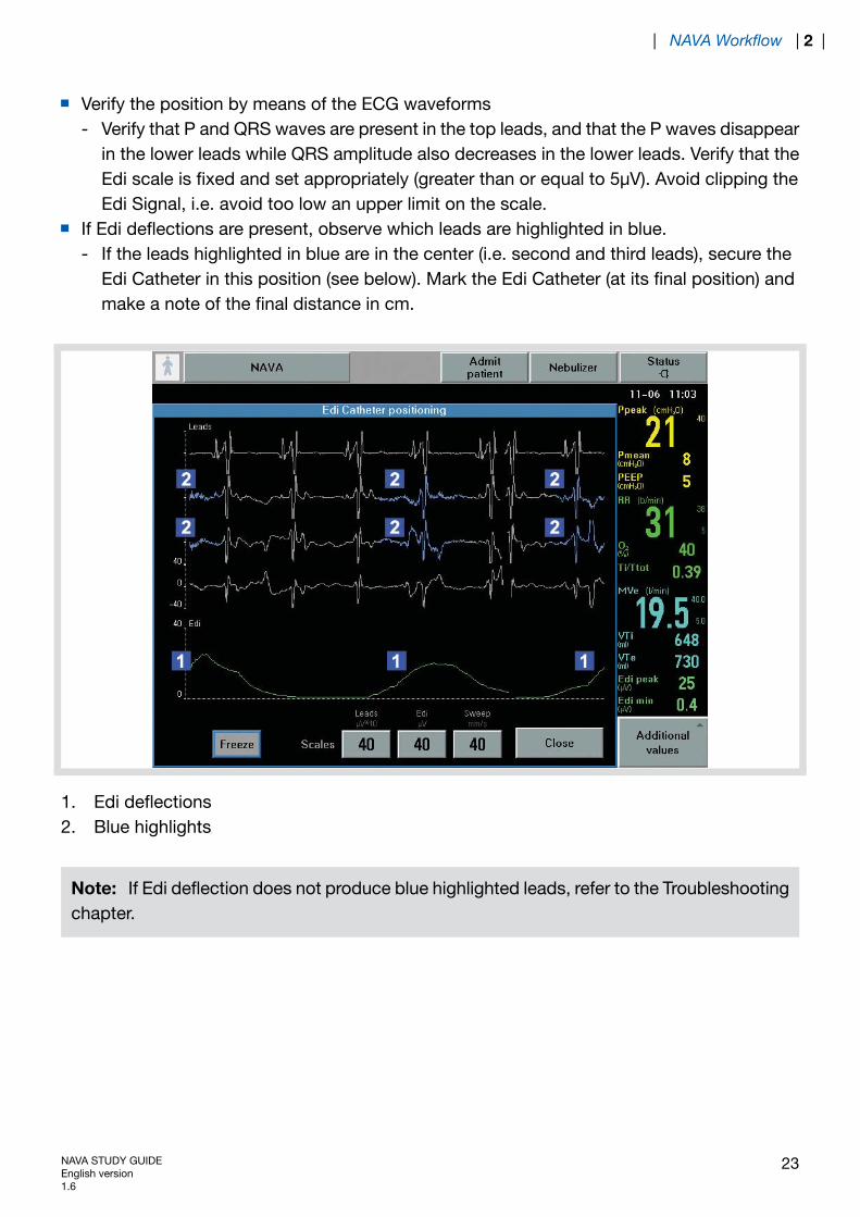
Verify the position by means of the ECG waveformsVerify that P and QRS waves are present in the top leads, and that the P waves disappearin the lower leads while QRS amplitude also decreases in the lower leads. Verify that theEdi scale is fixed and set appropriately (greater than or equal to 5μV). Avoid clipping theEdi Signal, i.e. avoid too low an upper limit on the scale.
-
If Edi deflections are present, observe which leads are highlighted in blue.If the leads highlighted in blue are in the center (i.e. second and third leads), secure theEdi Catheter in this position (see below). Mark the Edi Catheter (at its final position) andmake a note of the final distance in cm.
-
1. Edi deflections2. Blue highlights
Note: If Edi deflection does not produce blue highlighted leads, refer to the Troubleshootingchapter.
NAVA STUDY GUIDEEnglish version1.6
23
| NAVA Workflow | 2 |
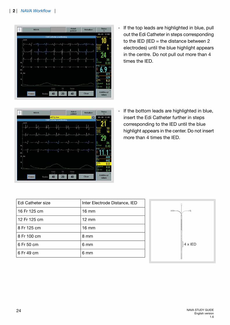
- If the top leads are highlighted in blue, pullout the Edi Catheter in steps correspondingto the IED (IED = the distance between 2electrodes) until the blue highlight appearsin the centre. Do not pull out more than 4times the IED.
- If the bottom leads are highlighted in blue,insert the Edi Catheter further in stepscorresponding to the IED until the bluehighlight appears in the center. Do not insertmore than 4 times the IED.
8075
7065
6055
50
4 x IED
Inter Electrode Distance, IEDEdi Catheter size
16 mm16 Fr 125 cm
12 mm12 Fr 125 cm
16 mm8 Fr 125 cm
8 mm8 Fr 100 cm
6 mm6 Fr 50 cm
6 mm6 Fr 49 cm
24 NAVA STUDY GUIDEEnglish version
1.6
| 2 | NAVA Workflow |
2.7 SECURE THE EDI CATHETER
As a final verification, check:correct position of the marking on the Edi Catheter;-
- appearance of the ECG waveforms;- appearance of the blue highlights on the waveforms.If this does not produce a satisfactory result, refer to the Troubleshooting chapter.Secure the Edi Catheter. Ensure that the Edi Catheter is not secured to the endotrachealtube.
IMPORTANT: Follow hospital routines to check the position of the Edi Catheter when usedas a gastric feeding tube.
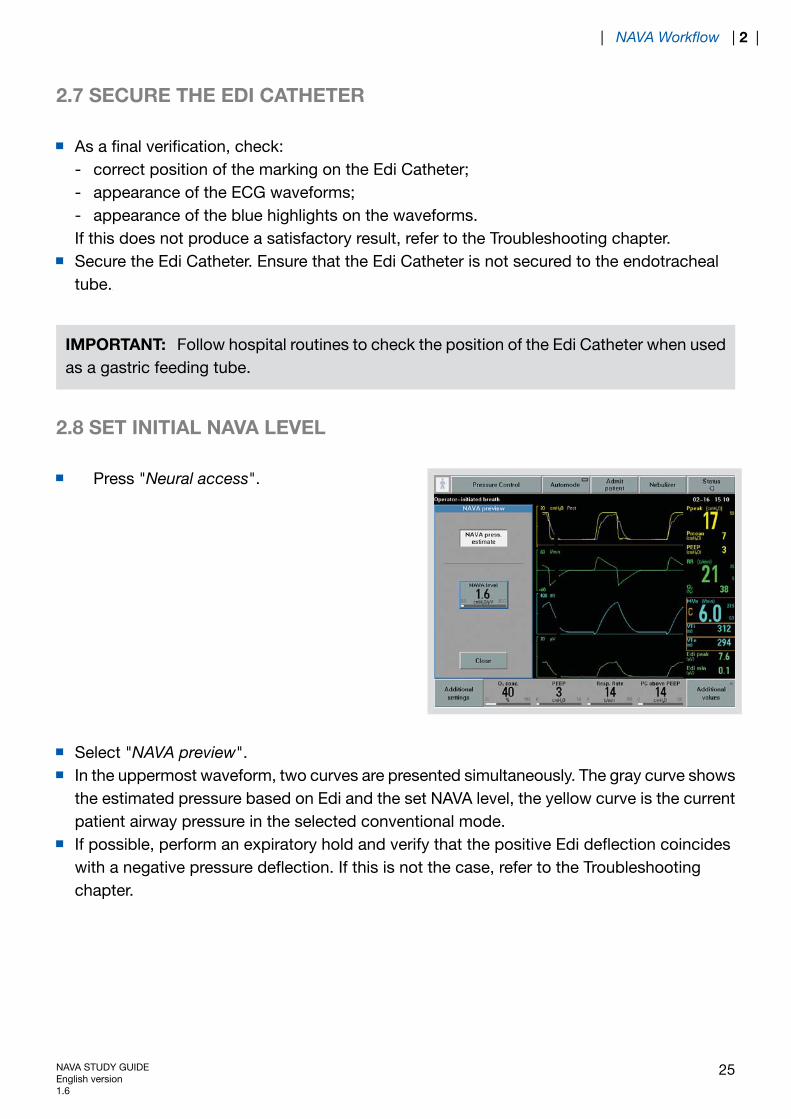
2.8 SET INITIAL NAVA LEVEL
Press "Neural access".
Select "NAVA preview".In the uppermost waveform, two curves are presented simultaneously. The gray curve showsthe estimated pressure based on Edi and the set NAVA level, the yellow curve is the currentpatient airway pressure in the selected conventional mode.If possible, perform an expiratory hold and verify that the positive Edi deflection coincideswith a negative pressure deflection. If this is not the case, refer to the Troubleshootingchapter.
NAVA STUDY GUIDEEnglish version1.6
25
| NAVA Workflow | 2 |
Press "NAVA level" and use the Main rotary dial to set the NAVA level. As a guide, the firstNAVA level to be tried should be the same or a little below the pressure used in the currentmode of ventilation.Press "Close" to save the NAVA level. The NAVA level will be transferred to the NAVAventilation mode window. Note that the patient is still being ventilated in the conventionalmode and that this is an estimate of the pressure to be delivered with NAVA.
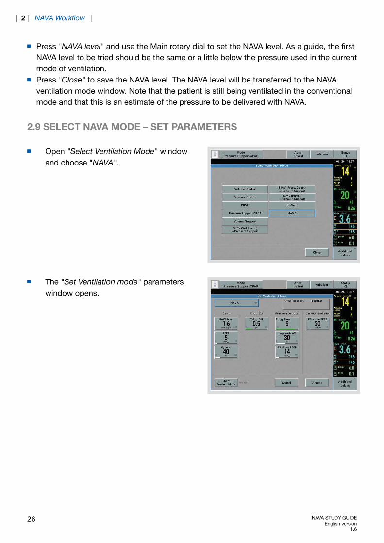
2.9 SELECT NAVA MODE – SET PARAMETERS
Open "Select Ventilation Mode" windowand choose "NAVA".
The "Set Ventilation mode" parameterswindow opens.
26 NAVA STUDY GUIDEEnglish version
1.6
| 2 | NAVA Workflow |

Basic and Trigg. Edi
- NAVA level (cmH2O/μV)- PEEP (cmH2O)- Oxygen concentration (%)- Trigger Edi (μV). Default setting is 0.5 μV (0 - 2 μV).
Pressure Support
- Trigger Sensitivity- Inspiratory Cycle off (%)- PS above PEEP (cmH2O)
Backup ventilation
- PC above PEEP (cmH2O)
NAVA STUDY GUIDEEnglish version1.6
27
| NAVA Workflow | 2 |
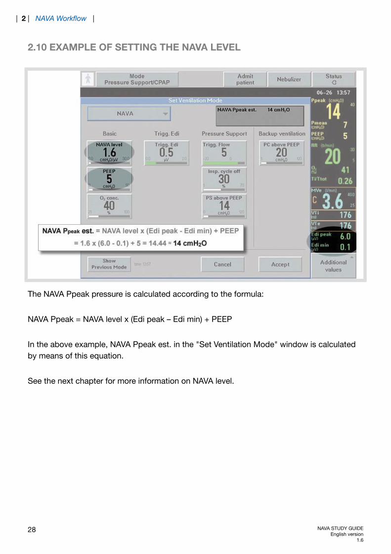
2.10 EXAMPLE OF SETTING THE NAVA LEVEL
The NAVA Ppeak pressure is calculated according to the formula:
NAVA Ppeak = NAVA level x (Edi peak – Edi min) + PEEP
In the above example, NAVA Ppeak est. in the "Set Ventilation Mode" window is calculatedby means of this equation.
See the next chapter for more information on NAVA level.
28 NAVA STUDY GUIDEEnglish version
1.6
| 2 | NAVA Workflow |

3 MODE DESCRIPTION
TABLE OF CONTENTS
30|Mode description3
31|NAVA level3.132|Trigger level3.233|NAVA Respiration Cycle3.334|Additional settings3.435|Running in NAVA mode3.536|Suctioning/disconnection in NAVA3.5.136|Neuro Ventilatory Tool (NVT)3.637|Monitoring of the Edi signal3.738|NAVA backup function3.839|NAVA (PS)3.939|Switching to NAVA (PS)3.9.139|Switching back from NAVA (PS) to
NAVA3.9.2
40|Alarm for asynchrony3.1040|Back to NAVA3.10.1
NAVA STUDY GUIDEEnglish version1.6
29
| Mode description | 3 |

3 MODE DESCRIPTION
NAVA ventilation mode is only available in Invasive ventilation.
There are four basic settings: NAVA level, PEEP, O2 conc. and Edi trigg.NAVA Level setting – value transferred from NAVA preview (0-30 cmH20/μV). Defaultsetting is 1.0 cmH2O/μV.
-
- The Edi trigger level can be set between 0.0 and 2.0 μV.Pressure support: select values for Pneumatic trigger level, Inspiratory cycle off and PressureSupport level.Back-up ventilation: select the Pressure back-up level to achieve adequate ventilation incase of apnea.Press “Accept” to accept the settings and proceed with NAVA ventilation.
30 NAVA STUDY GUIDEEnglish version
1.6
| 3 | Mode description |
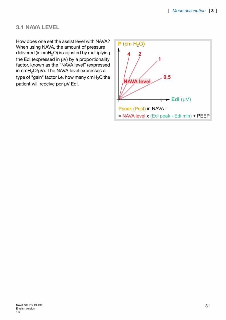
3.1 NAVA LEVEL
P (cm H2O)
Ppeak (Pest)
4 21
0,5
P (cm H2O)
Edi (μV)
Ppeak (Pest) in NAVA = = NAVA level x (Edi peak - Edi min) + PEEP
NAVA level
How does one set the assist level with NAVA?When using NAVA, the amount of pressuredelivered (in cmH2O) is adjusted by multiplyingthe Edi (expressed in μV) by a proportionalityfactor, known as the “NAVA level” (expressedin cmH2O/μV). The NAVA level expresses atype of "gain" factor i.e. how many cmH2O thepatient will receive per μV Edi.
NAVA STUDY GUIDEEnglish version1.6
31
| Mode description | 3 |
3.2 TRIGGER LEVEL
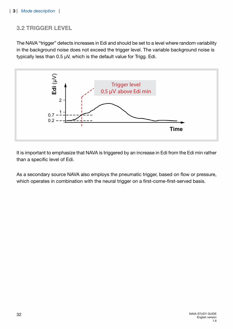
The NAVA “trigger” detects increases in Edi and should be set to a level where random variabilityin the background noise does not exceed the trigger level. The variable background noise istypically less than 0.5 μV, which is the default value for Trigg. Edi.
Time
2
10.70.2
Edi(
μV)
Trigger level0.5 μV above Edi min
It is important to emphasize that NAVA is triggered by an increase in Edi from the Edi min ratherthan a specific level of Edi.
As a secondary source NAVA also employs the pneumatic trigger, based on flow or pressure,which operates in combination with the neural trigger on a first-come-first-served basis.
32 NAVA STUDY GUIDEEnglish version
1.6
| 3 | Mode description |
3.3 NAVA RESPIRATION CYCLE
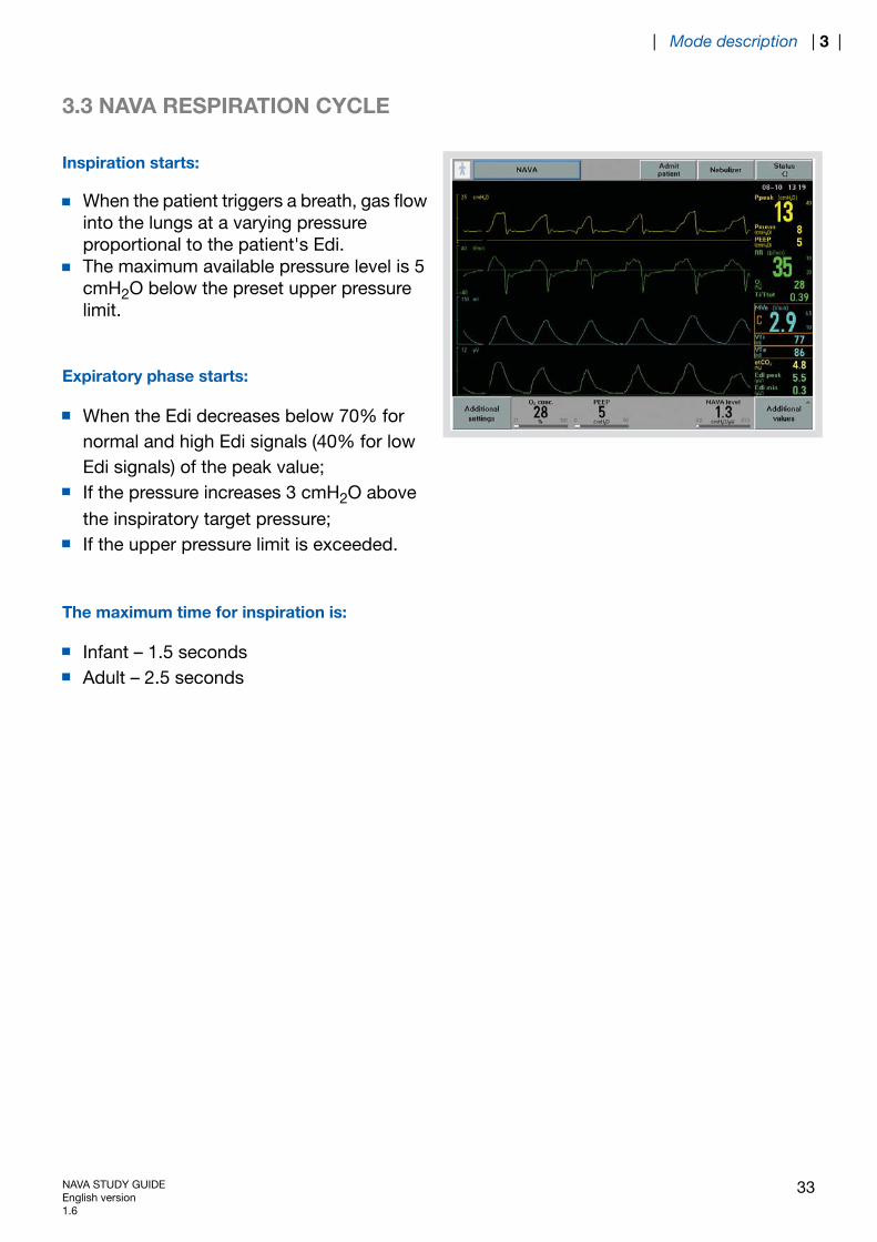
Inspiration starts:
When the patient triggers a breath, gas flowinto the lungs at a varying pressureproportional to the patient's Edi.The maximum available pressure level is 5cmH2O below the preset upper pressurelimit.
Expiratory phase starts:
When the Edi decreases below 70% fornormal and high Edi signals (40% for lowEdi signals) of the peak value;If the pressure increases 3 cmH2O abovethe inspiratory target pressure;If the upper pressure limit is exceeded.
The maximum time for inspiration is:
Infant – 1.5 secondsAdult – 2.5 seconds
NAVA STUDY GUIDEEnglish version1.6
33
| Mode description | 3 |
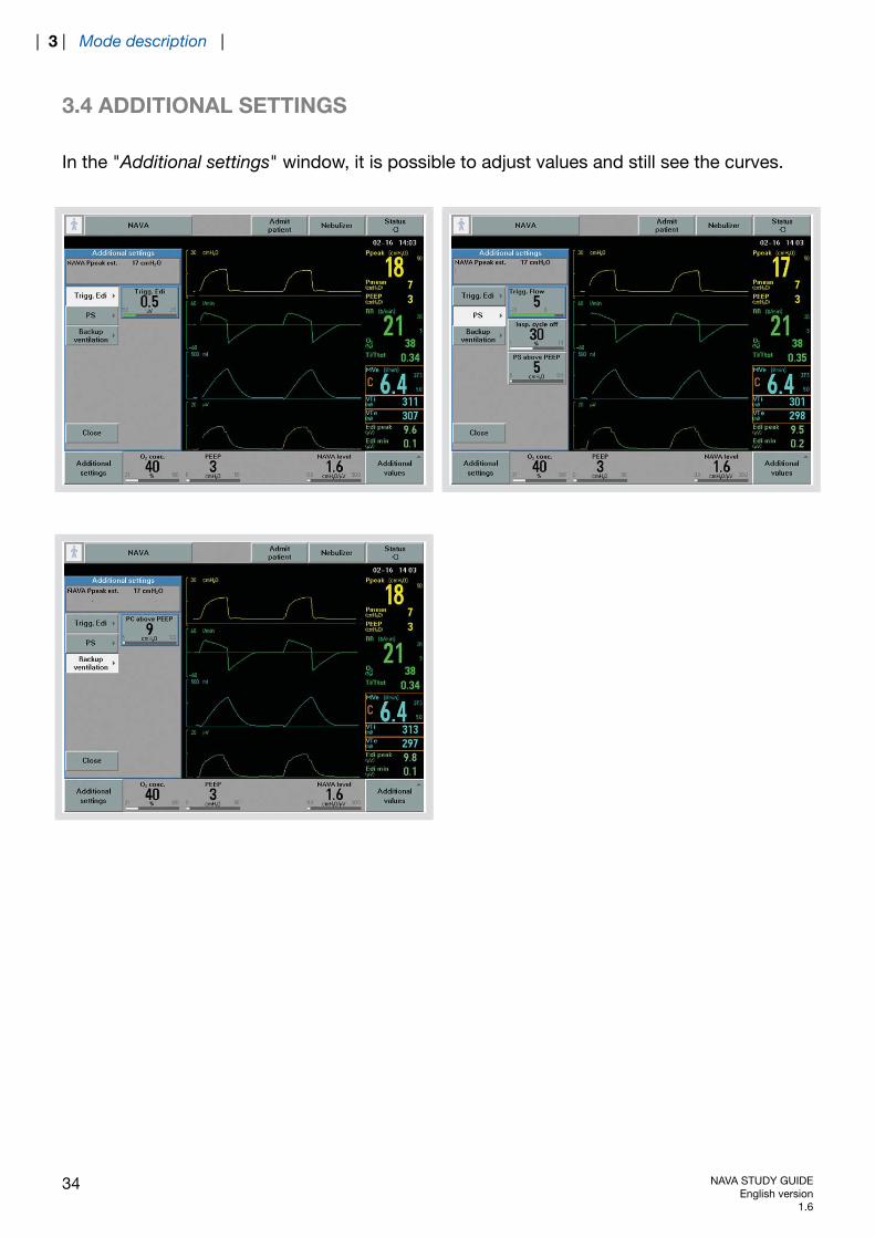
3.4 ADDITIONAL SETTINGS
In the "Additional settings" window, it is possible to adjust values and still see the curves.
34 NAVA STUDY GUIDEEnglish version
1.6
| 3 | Mode description |
3.5 RUNNING IN NAVA MODE
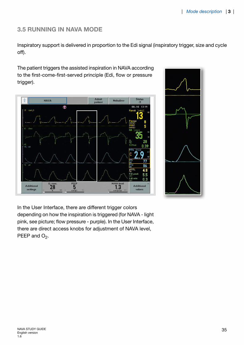
Inspiratory support is delivered in proportion to the Edi signal (inspiratory trigger, size and cycleoff).
The patient triggers the assisted inspiration in NAVA accordingto the first-come-first-served principle (Edi, flow or pressuretrigger).
In the User Interface, there are different trigger colorsdepending on how the inspiration is triggered (for NAVA - lightpink, see picture; flow pressure - purple). In the User Interface,there are direct access knobs for adjustment of NAVA level,PEEP and O2.
NAVA STUDY GUIDEEnglish version1.6
35
| Mode description | 3 |
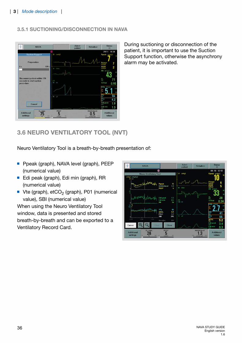
3.5.1 SUCTIONING/DISCONNECTION IN NAVA
During suctioning or disconnection of thepatient, it is important to use the SuctionSupport function, otherwise the asynchronyalarm may be activated.
3.6 NEURO VENTILATORY TOOL (NVT)
Neuro Ventilatory Tool is a breath-by-breath presentation of:
Ppeak (graph), NAVA level (graph), PEEP(numerical value)Edi peak (graph), Edi min (graph), RR(numerical value)Vte (graph), etCO2 (graph), P01 (numericalvalue), SBI (numerical value)
When using the Neuro Ventilatory Toolwindow, data is presented and storedbreath-by-breath and can be exported to aVentilatory Record Card.
36 NAVA STUDY GUIDEEnglish version
1.6
| 3 | Mode description |
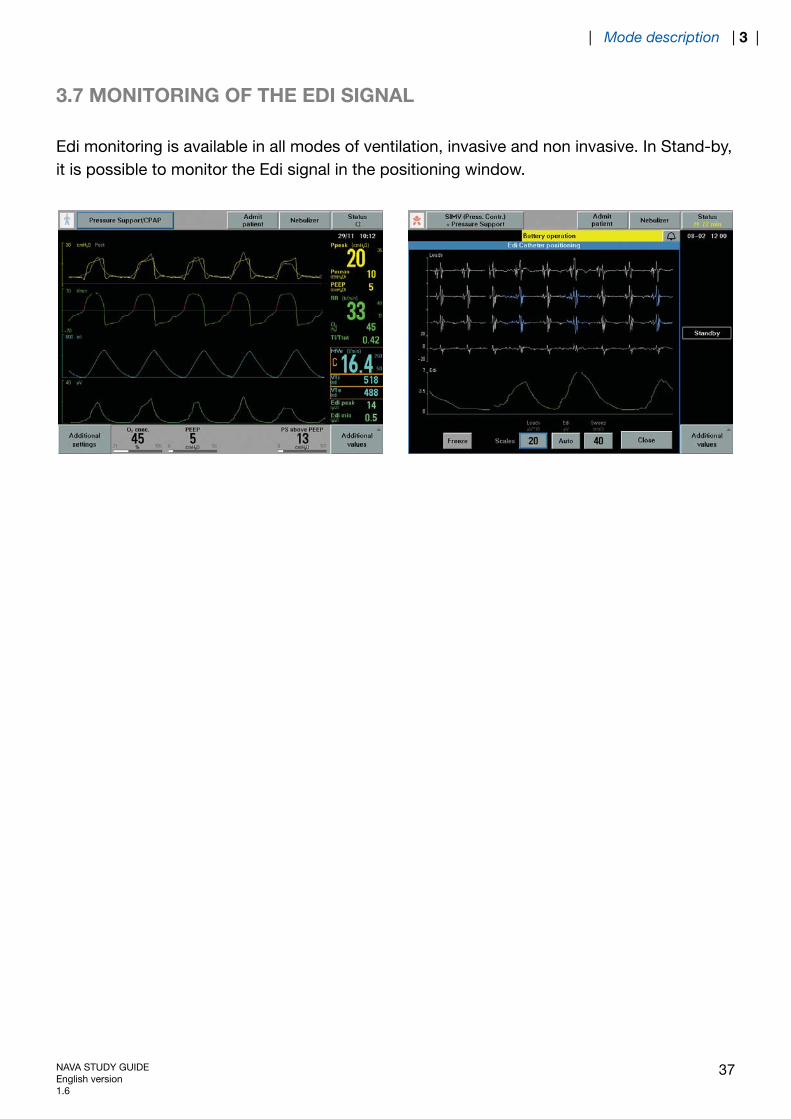
3.7 MONITORING OF THE EDI SIGNAL
Edi monitoring is available in all modes of ventilation, invasive and non invasive. In Stand-by,it is possible to monitor the Edi signal in the positioning window.
NAVA STUDY GUIDEEnglish version1.6
37
| Mode description | 3 |
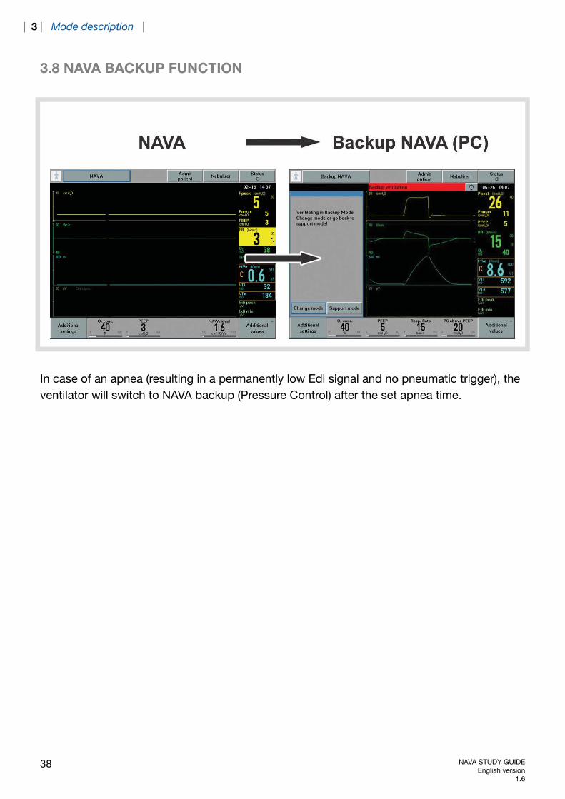
3.8 NAVA BACKUP FUNCTION
In case of an apnea (resulting in a permanently low Edi signal and no pneumatic trigger), theventilator will switch to NAVA backup (Pressure Control) after the set apnea time.
38 NAVA STUDY GUIDEEnglish version
1.6
| 3 | Mode description |
3.9 NAVA (PS)
3.9.1 SWITCHING TO NAVA (PS)
The ventilator switches from NAVA to NAVA (PS) if one or more of the following conditions arefulfilled during NAVA ventilation:
The Edi respiratory rate differs from the pneumatic respiratory rate by more than 25% forat least 5 s. The calculated respiratory rates are based on the last 20 s.The Edi Ti/Ttot is more than 0.5, calculated over the last 20 s if the catheter position isclassified as invalid.The Edi Ti/Ttot is more than 0.6, calculated over the last 20 s if the catheter position isclassified as valid.The Edi Catheter is disconnected.There is ECG leakage into the Edi signal.
Note: Pneumatic respiratory rate and Ti/Ttot are shown in the User Interface. Edi respiratoryrate and Edi Ti/Ttot are not shown on the User Interface.
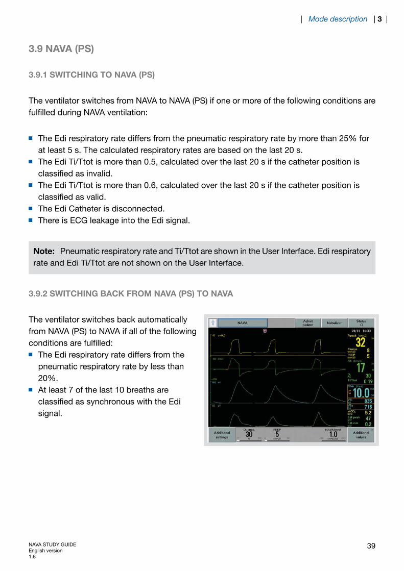
3.9.2 SWITCHING BACK FROM NAVA (PS) TO NAVA
The ventilator switches back automaticallyfrom NAVA (PS) to NAVA if all of the followingconditions are fulfilled:
The Edi respiratory rate differs from thepneumatic respiratory rate by less than20%.At least 7 of the last 10 breaths areclassified as synchronous with the Edisignal.
NAVA STUDY GUIDEEnglish version1.6
39
| Mode description | 3 |
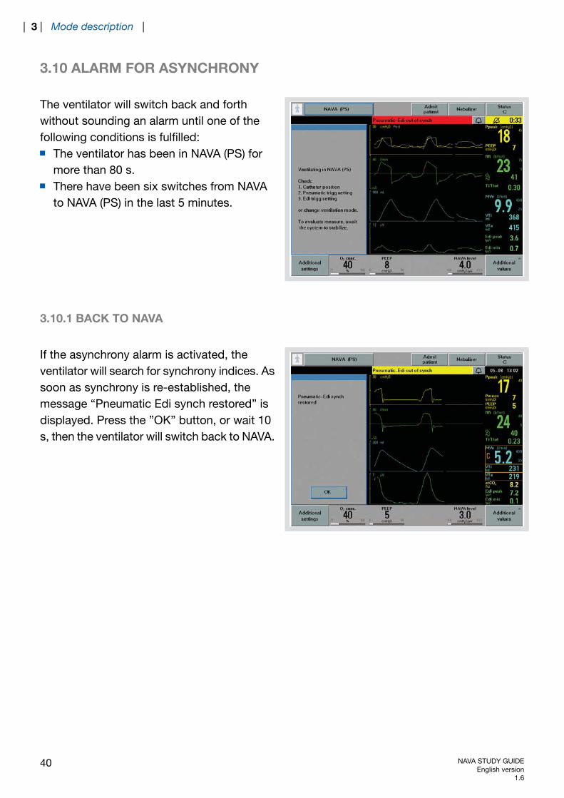
3.10 ALARM FOR ASYNCHRONY
The ventilator will switch back and forthwithout sounding an alarm until one of thefollowing conditions is fulfilled:
The ventilator has been in NAVA (PS) formore than 80 s.There have been six switches from NAVAto NAVA (PS) in the last 5 minutes.
3.10.1 BACK TO NAVA
If the asynchrony alarm is activated, theventilator will search for synchrony indices. Assoon as synchrony is re-established, themessage “Pneumatic Edi synch restored” isdisplayed. Press the ”OK” button, or wait 10s, then the ventilator will switch back to NAVA.
40 NAVA STUDY GUIDEEnglish version
1.6
| 3 | Mode description |
4 TROUBLESHOOTING
TABLE OF CONTENTS
42|Troubleshooting4
42|Low or no Edi signal4.143|The Edi signal is present, but there are no
blue highlights on the ECG waveforms4.2
44|Ways to facilitate synchrony and transitionfrom NAVA (PS) back to NAVA
4.3
NAVA STUDY GUIDEEnglish version1.6
41
| Troubleshooting | 4 |

4 TROUBLESHOOTING
4.1 LOW OR NO EDI SIGNAL
If a low or no Edi signal is detected:
Verify the Edi Catheter positioning.Verify that the effects of muscle relaxants have worn off.Verify the patient's sedation level. The apneic threshold might be higher due to CNSdepressant drugs.Verify, by means of blood gas or end tidal CO2, that the patient is not hyperventilated, asthis may affect the Edi.Too high a PEEP level and/or too high support pressures may diminish diaphragm electricalactivity to a level where it is difficult to detect. In this case, reduction of these levels mayrestore Edi and diaphragm activity.
42 NAVA STUDY GUIDEEnglish version
1.6
| 4 | Troubleshooting |
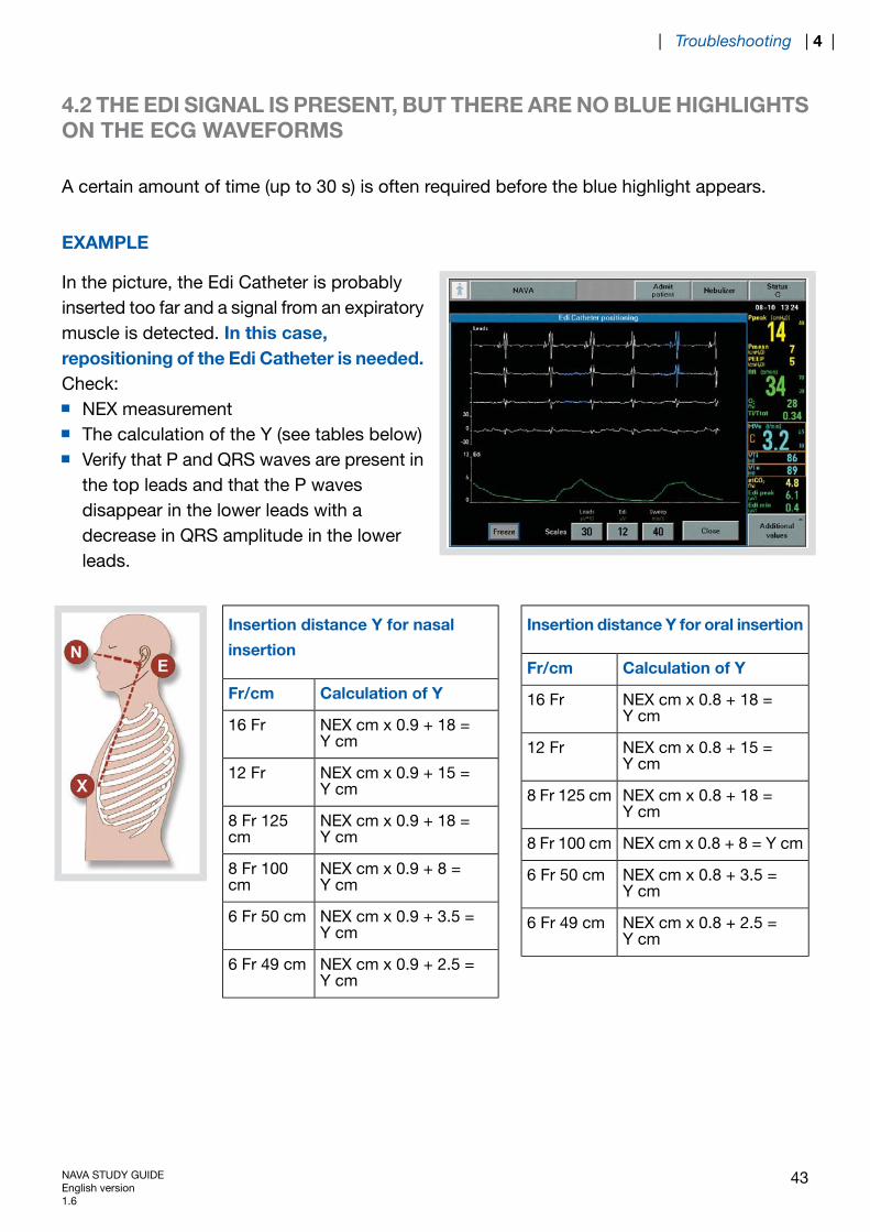
4.2 THE EDI SIGNAL IS PRESENT, BUT THERE ARE NO BLUE HIGHLIGHTSON THE ECG WAVEFORMS
A certain amount of time (up to 30 s) is often required before the blue highlight appears.
EXAMPLE
In the picture, the Edi Catheter is probablyinserted too far and a signal from an expiratorymuscle is detected. In this case,repositioning of the Edi Catheter is needed.Check:
NEX measurementThe calculation of the Y (see tables below)Verify that P and QRS waves are present inthe top leads and that the P wavesdisappear in the lower leads with adecrease in QRS amplitude in the lowerleads.
Insertion distance Y for oral insertion
Calculation of YFr/cm
NEX cm x 0.8 + 18 =Y cm
16 Fr
NEX cm x 0.8 + 15 =Y cm
12 Fr
NEX cm x 0.8 + 18 =Y cm
8 Fr 125 cm
NEX cm x 0.8 + 8 = Y cm8 Fr 100 cm
NEX cm x 0.8 + 3.5 =Y cm
6 Fr 50 cm
NEX cm x 0.8 + 2.5 =Y cm
6 Fr 49 cm
Insertion distance Y for nasal
insertion
Calculation of YFr/cm
NEX cm x 0.9 + 18 =Y cm
16 Fr
NEX cm x 0.9 + 15 =Y cm
12 Fr
NEX cm x 0.9 + 18 =Y cm
8 Fr 125cm
NEX cm x 0.9 + 8 =Y cm
8 Fr 100cm
NEX cm x 0.9 + 3.5 =Y cm
6 Fr 50 cm
NEX cm x 0.9 + 2.5 =Y cm
6 Fr 49 cm
NAVA STUDY GUIDEEnglish version1.6
43
| Troubleshooting | 4 |

4.3 WAYS TO FACILITATE SYNCHRONY AND TRANSITION FROM NAVA(PS) BACK TO NAVA
If the amplitude of the Edi signal is low during NAVA (PS), the pressure support level maysupress the Edi signal. Consider lowering the pressure support level.If there is leakage in the patient´s circuit, consider lowering the pneumatic trigger sensitivityin order to minimize the autotriggering.
44 NAVA STUDY GUIDEEnglish version
1.6
| 4 | Troubleshooting |

5 ALARMS
TABLE OF CONTENTS
46|Alarms5
47|Alarm for asynchrony5.147|Back to NAVA5.1.1
NAVA STUDY GUIDEEnglish version1.6
45
| Alarms | 5 |

5 ALARMS
"Pressure regulation limited" alarm – activated 5 cmH2O below Upper pressure limit.Patient related alarm: "Edi activity low" – can be silenced.
Message and dialog when Edi Module and/or Edi Catheter are disconnected.High priority alarm when Edi Module and/or Edi Catheter are disconnected in NAVA.
46 NAVA STUDY GUIDEEnglish version
1.6
| 5 | Alarms |

5.1 ALARM FOR ASYNCHRONY
The ventilator will switch back and forthwithout sounding an alarm until one of thefollowing conditions is fulfilled:
The ventilator has been in NAVA (PS) formore than 80 s.There have been six switches from NAVAto NAVA (PS) in the last 5 minutes
5.1.1 BACK TO NAVA
If the asynchrony alarm is activated, theventilator will search for synchrony indices. Assoon as synchrony is re-established, themessage “Pneumatic Edi synch restored” isdisplayed. Press the ”OK” button, or wait 10s, then the ventilator will switch back to NAVA.
NAVA STUDY GUIDEEnglish version1.6
47
| Alarms | 5 |
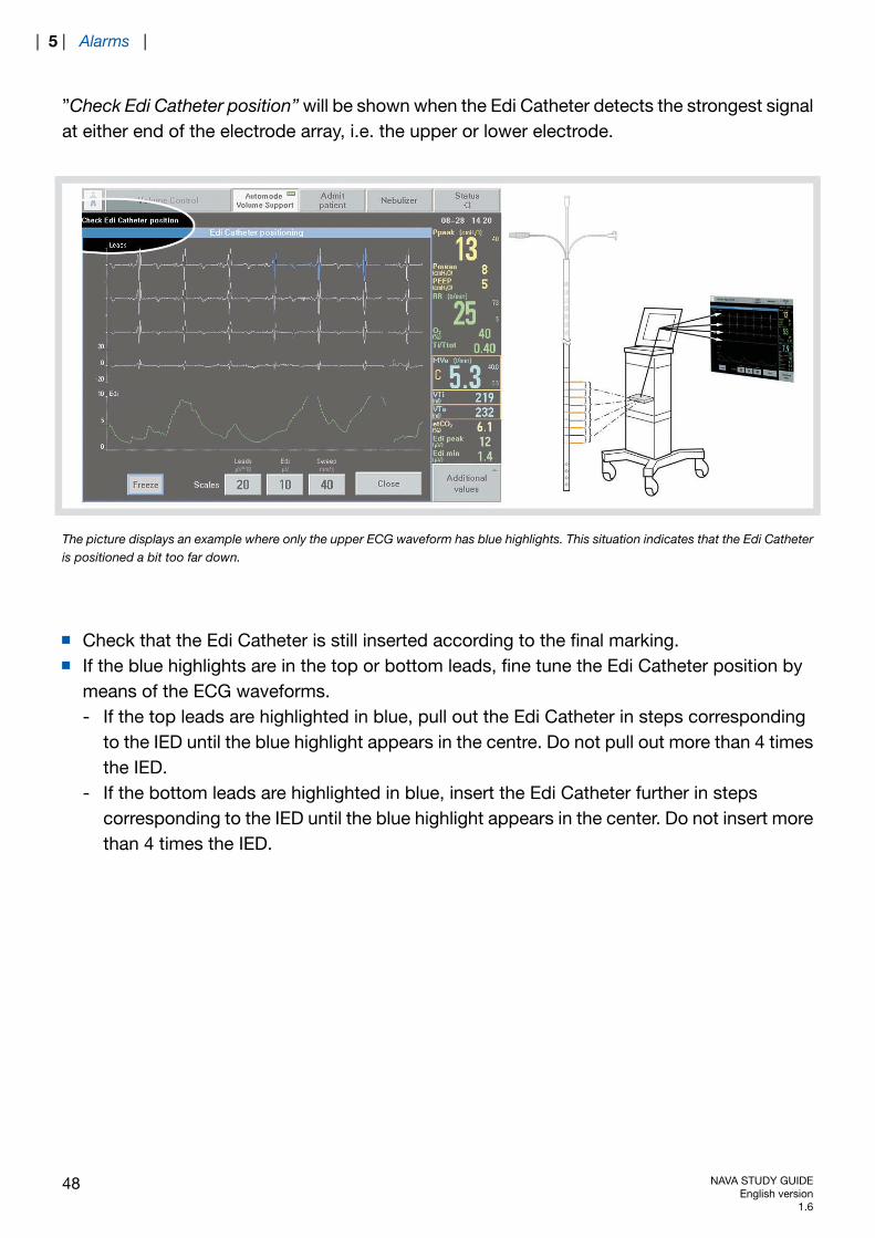
”Check Edi Catheter position” will be shown when the Edi Catheter detects the strongest signalat either end of the electrode array, i.e. the upper or lower electrode.
The picture displays an example where only the upper ECG waveform has blue highlights. This situation indicates that the Edi Catheteris positioned a bit too far down.
Check that the Edi Catheter is still inserted according to the final marking.If the blue highlights are in the top or bottom leads, fine tune the Edi Catheter position bymeans of the ECG waveforms.- If the top leads are highlighted in blue, pull out the Edi Catheter in steps corresponding
to the IED until the blue highlight appears in the centre. Do not pull out more than 4 timesthe IED.
- If the bottom leads are highlighted in blue, insert the Edi Catheter further in stepscorresponding to the IED until the blue highlight appears in the center. Do not insert morethan 4 times the IED.
48 NAVA STUDY GUIDEEnglish version
1.6
| 5 | Alarms |
6 REFERENCES FOR NAVA STUDY GUIDE
6.1 REFERENCES
1. Sinderby C, Beck J. Neurally Adjusted Ventilatory Assist (NAVA): An Update and Summaryof Experiences. Neth J Crit Care 2007:11(5): 243-252.
2. Sinderby C, Beck J, Spahija J, de Marchie M, Lacroix J, Navalesi P, Slutsky AS. Inspiratorymuscle unloading by neurally adjusted ventilatory assist during maximal inspiratory efforts inhealthy subjects. Chest 2007; 131(3): 711-717.
3. Beck J, Campoccia F, Allo JC, Brander L, Brunet F, Slutsky AS, Sinderby C. Improvedsynchrony and respiratory unloading by neurally adjusted ventilatory assist (NAVA) in lung-injuredrabbits. Pediatr Res 2007; 61(3), 289-294.
4. Allo JC, Beck JC, Brander L, Brunet F, Slutsky AS, Sinderby CA. Influence of neurally adjustedventilatory assist and positive end-expiratory pressure on breathing pattern in rabbits withacute lung injury. Crit Care Med 2006; 34(12): 2997-3004.
5. Emeriaud G, Beck J,Tucci M, Lacroix J, Sinderby C. Diaphragm electrical activity duringexpiration in mechanically ventilated infants. Pediatr Res 2006; 59(5): 705-710.
6. Beck J, Gottfried SB, Navalesi P, SkrobikY, Comtois N, Rossini M. Sinderby C. Electricalactivation of the diaphragm during pressure support ventilation in acute respiratory failure. AmJ Respir Crit Care Med 2001; 164(3): 419-424
7. Sinderby C, Spahija, J, Beck J, Kaminski D,Yan S. Comtois N, Sliwinski P. Diaphragmactivation during exercise in chronic obstructive pulmonary disease. Am J Respir Crit CareMed 2001; 163(7): 1637-1641.
8. Sinderby C, Navalesi P, Beck J, SkrobikY, Comtois N, Friberg S, Gottfried SB, LindstromL. Neural control of mechanical ventilation in respiratory failure. Nat Med 1999; 5(12): 1433-1436.
NAVA STUDY GUIDEEnglish version1.6
49
| References for NAVA Study Guide | 6 |

50 NAVA STUDY GUIDEEnglish version
1.6
| 6 | References for NAVA Study Guide |

Maquet Critical Care ABSE-171 95 Solna, SwedenPhone: +46 (0) 8 730 73 00www.maquet.com
For local contact:Please visit our websitewww.maquet.com
GETINGE Group is a leading global provider of equipment andsystems that contributes to quality enhancement and cost efficiencywithin healthcare and life sciences. Equipment, services andtechnologies are supplied under the brands ARJO for patient hygiene,patient handling and wound care, GETINGE for infection control andprevention within healthcare and life science and MAQUET forsurgical workplaces, cardiopulmonary and critical care.
© M
aque
t C
ritic
al C
are
AB
200
8. A
ll rig
hts
rese
rved
. • M
AQ
UE
T re
serv
es t
he r
ight
to
mod
ify t
he d
esig
n an
d s
pec
ifica
tions
con
tain
ed h
erei
n w
ithou
t p
rior
notic
e.•
Ord
er N
o. 6
6 75
357
• P
rinte
d in
Sw
eden
• 0
8041
6 •
Rev
: Rev
00
Eng
lish
•