servo press kit yjkp - advanced force mode...application note – servo press kit yjkp - advanced...
TRANSCRIPT
100206
Application note
Servo Press Kit YJKP - Advanced Force Mode
This Application Note describes the properties, operation and parameterization of the advanced force mode of the servo press kit YJKP.
YJKP

Title ................................................................................................... Servo Press Kit YJKP – Advanced Force Mode
Version ............................................................................................................................................................. 1.10
Document number ....................................................................................................................................... 100206
Original ................................................................................................................................................................ de
Author ............................................................................................................................................................. Festo
Last saved on ........................................................................................................................................ 05.02.2019
Copyright notice This documentation is the intellectual property of Festo AG & Co. KG, which also has the exclusive copyright. Any modification of the content, duplication or reprinting of this documentation as well as distribution to third par-ties can only be made with the express consent of Festo AG & Co. KG.
Festo AG & Co KG reserves the right to make modifications to this document in whole or in part. All brand and product names are trademarks or registered trademarks of their respective owners.
Legal notice Hardware, software, operating systems and drivers may only be used for the applications described and only in conjunction with components recommended by Festo AG & Co. KG.
Festo AG & Co. KG does not accept any liability for damages arising from the use of any incorrect or incomplete information contained in this documentation or any information missing therefrom.
Defects resulting from the improper treatment of devices and modules are excluded from the warranty.
The data and information specified in this document should not be used for the implementation of safety func-tions relating to the protection of personnel and machinery.
No liability is accepted for claims for damages arising from a failure or functional defect. In other respects, the regulations with regard to liability from the terms and conditions of delivery, payment and use of software of Festo AG & Co. KG, which can be found at www.festo.com and can be supplied on request, shall apply.
All data contained in this document do not represent guaranteed specifications, particularly with regard to func-tionality, condition or quality, in the legal sense.
The information in this document serves only as basic information for the implementation of a specific, hypo-thetical application and is in no way intended as a substitute for the operating instructions of the respective manufacturers or the design and testing of the respective application by the end user.
The operating instructions for Festo products can be found at www.festo.com/sp .
Users of this document (function and application) must verify that all functions described here also work cor-rectly in the application. Even after examining this document and while using the specifications contained herein, users nevertheless remain solely responsible for their own applications.
(Festo AG & CO. KG, D-73726 Esslingen, 2019) Internet: http://www.festo.com E-Mail: [email protected]

Table of contents
1 Utilised components/software ................................................................................................................... 5
2 Overview ..................................................................................................................................................... 6
3 Parameterization ........................................................................................................................................ 7
3.1 Influences .................................................................................................................................................... 7
3.2 Pressing parameters.................................................................................................................................... 7
3.3 Limits ........................................................................................................................................................... 7
3.4 Velocity switch (optional) ............................................................................................................................ 8
3.5 Parameterisation procedure ...................................................................................................................... 10
4 Application examples ............................................................................................................................... 11
4.1 Determination of the pressing parameters ................................................................................................ 11
4.1.1 Sample application ...................................................................................................................... 11 4.1.2 Initial pressing parameters .......................................................................................................... 12 4.1.3 Adapting limit values ................................................................................................................... 12 4.1.4 Determining the optimum pressing parameters .......................................................................... 13
4.2 Creating an evaluation method ................................................................................................................. 15
4.3 Comparison of the advanced force mode with the force mode .................................................................. 16
4.4 Step-by-step increasing and decreasing of force ....................................................................................... 19


components/software
Application Note – Servo Press Kit YJKP - Advanced Force Mode 1.10 Page 5 of 19
1 components/software
Type/name Software/firmware version Date of manufacture
Servo Press Kit YJKP General --
Application software for YJKP (GSAY-A4-F0-Z4-1.3.3)
V1.3.3 --
Firmware for controller (CECC-X) V3.4.6 --
Firmware for motor controller (CMMP-AS)
V4.0.1501.2.4 --
Table 1.1: components/software

Overview
Page 6 of 19 Application Note – Servo Press Kit YJKP - Advanced Force Mode – 1.10
2 Overview The intention of the advanced force mode function is to achieve a certain target force. As soon as this force has been reached without violating a limit value, the step will be fulfilled as successful.
In contrast with force mode, a parameterisable braking ramp is used. This reduces the pressing velocity (v_max) from 100% to 1%. As a result, the target force is achieved more precisely and faster.
The advanced force mode has the following properties:
• It is selected as a function in the sequencer. • Both a force build-up and a force release are possible. • The advanced force mode can be used several times in a program in the sequencer.
• The limits “Maximum position” and “Maximum force” are available, which can be monitored through-
out the entire advanced force mode.
• Graphic displays for force/time [F/t] and force/displacement [F/s] are also provided for the analysis and evaluation of the process.
• Optionally, the advanced force mode includes the driving profile velocity switch. The process time can
be optimised using this profile.
• The respective velocity limits of the sizes also apply during advanced force mode.
• The maximum duration of the advanced force mode is 50 s. After that, it is aborted.

Parameterization
Application Note – Servo Press Kit YJKP - Advanced Force Mode 1.10 Page 7 of 19
3 Parameterization
3.1 Influences
During the parameterization of the advanced force mode, different influences must be taken into consideration:
• Velocity: If the velocity is too high, the target force can be exceeded, and the pressing or
servo press can be damaged.
• Pressing/frame: The Force start braking and Velocity parameters must be adapted depending on the
rigidity of the pressing.
• Target force: The Force start braking and Velocity parameters must be adapted depending on the
target force.
3.2 Pressing parameters
• Target force [N]: The force to be pressed.
• Force start braking [N]: The force from which the reduction in velocity begins.
• Velocity [mm/s]: The maximum possible velocity during the pressing procedure.
3.3 Limits
If one of the limits is exceeded, the set “failure reaction” is either executed or aborted. Note: The recommended “failure reaction” must be activated if this setting is possible in the application!
• Max. position [mm]: If the maximum position (absolute) is exceeded, the function is aborted.
• Max. force [N]: If the force is exceeded, the function is aborted.
Size Up to
0.8 kN
Up to
1.5 kN
Up to
4 kN
Up to
7 kN
Up to
12 kN
Up to
17 kN
Limit of max. force [kN] 0.84 1.575 4.2 7.35 12.6 17.85

Parameterization
Page 8 of 19 Application Note – Servo Press Kit YJKP - Advanced Force Mode – 1.10
3.4 Velocity switch (optional) Velocity switching can be activated optionally in advanced force mode. Using this function, an intermediate posi-tion (e.g., position shortly upstream of the pressing) can be approached at high velocity (v_max_2). From there, the system brakes to the set velocity (v_max) without stopping.
With this switching of the speed, the cycle time can be reduced in contrast with a separate positioning step. This is illustrated in the following diagrams:

Parameterization
Application Note – Servo Press Kit YJKP - Advanced Force Mode 1.10 Page 9 of 19
Parameter
• Act: Activation of velocity switch
• Middle position [mm]: At this position, the velocity starts to be reduced from v_max_2 to
v_max.
• Approach velocity [mm/s]: Velocity from the start of force control up to the
middle position (v_max_2)
Note: The velocity is not reduced until the middle position is reached.
When determining the middle position, you must ensure that it is not too close to or on the pressing. Otherwise an excessive approach velocity (v_max_2) can lead to damage to the press and/or part.
Parameterization
Page 10 of 19 Application Note – Servo Press Kit YJKP - Advanced Force Mode – 1.10
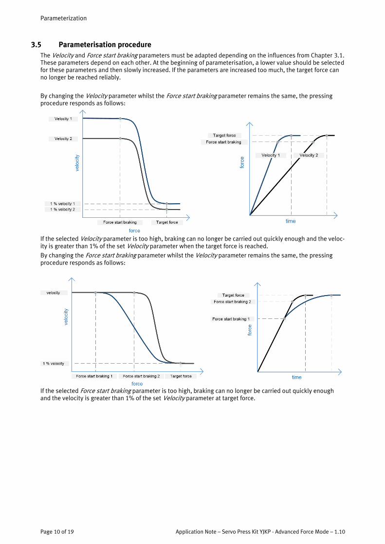
3.5 Parameterisation procedure The Velocity and Force start braking parameters must be adapted depending on the influences from Chapter 3.1. These parameters depend on each other. At the beginning of parameterisation, a lower value should be selected for these parameters and then slowly increased. If the parameters are increased too much, the target force can no longer be reached reliably.
By changing the Velocity parameter whilst the Force start braking parameter remains the same, the pressing procedure responds as follows:
If the selected Velocity parameter is too high, braking can no longer be carried out quickly enough and the veloc-ity is greater than 1% of the set Velocity parameter when the target force is reached.
By changing the Force start braking parameter whilst the Velocity parameter remains the same, the pressing procedure responds as follows:
If the selected Force start braking parameter is too high, braking can no longer be carried out quickly enough and the velocity is greater than 1% of the set Velocity parameter at target force.
Application examples
Application Note – Servo Press Kit YJKP - Advanced Force Mode 1.10 Page 11 of 19
4 Application examples
4.1 Determination of the pressing parameters
4.1.1 Sample application
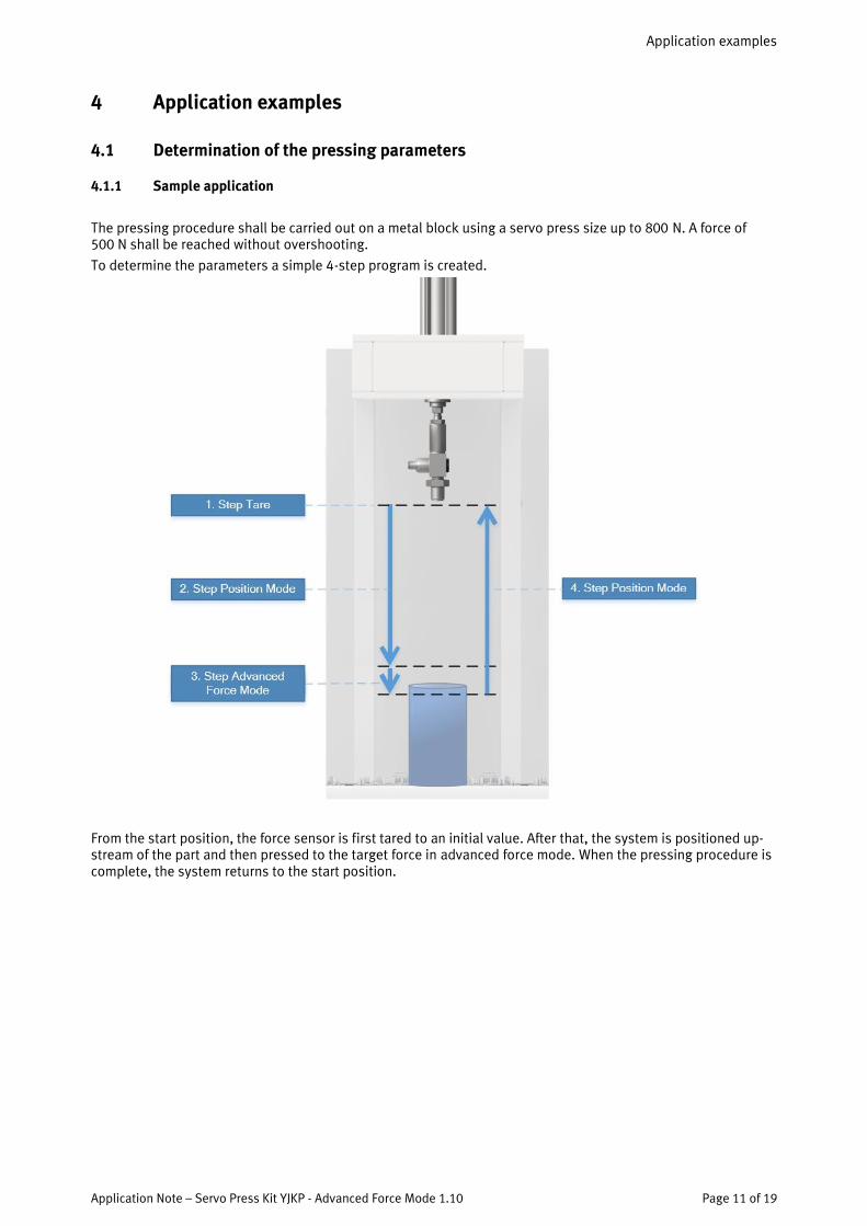
The pressing procedure shall be carried out on a metal block using a servo press size up to 800 N. A force of 500 N shall be reached without overshooting.
To determine the parameters a simple 4-step program is created.
From the start position, the force sensor is first tared to an initial value. After that, the system is positioned up-stream of the part and then pressed to the target force in advanced force mode. When the pressing procedure is complete, the system returns to the start position.

Application examples
Page 12 of 19 Application Note – Servo Press Kit YJKP - Advanced Force Mode – 1.10
4.1.2 Initial pressing parameters
In Step 1/4, the initial pressing parameters are set:
• The recording of the advanced force mode step must be activated in order to assess and adapt the pressing parameters using the recorded curve.
• The target force of 500 N is set. • We recommend that a low force is set under the Force start braking parameter and a slow velocity is set
under the Velocity parameter. Both parameters are adapted later using the method from Chapter 3.5.
4.1.3 Adapting limit values
• The limit values must be adapted depending on the mechanical structure and application.
Application examples
Application Note – Servo Press Kit YJKP - Advanced Force Mode 1.10 Page 13 of 19
4.1.4 Determining the optimum pressing parameters
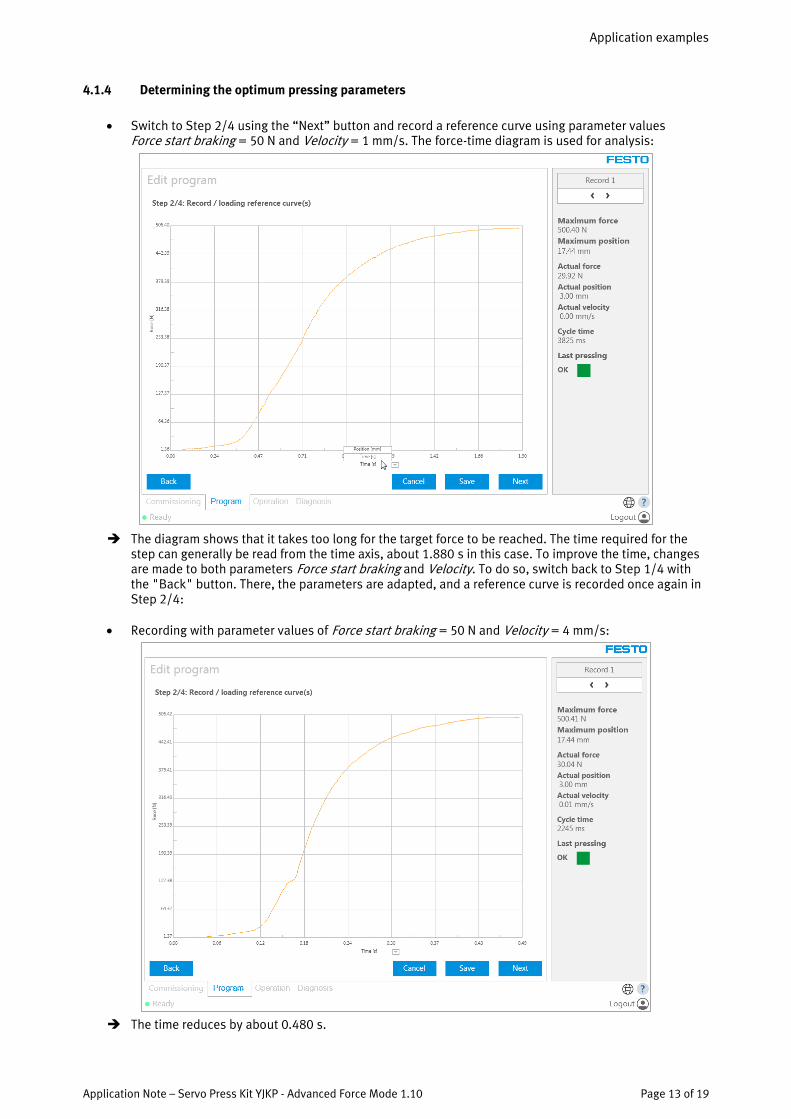
• Switch to Step 2/4 using the “Next” button and record a reference curve using parameter values Force start braking = 50 N and Velocity = 1 mm/s. The force-time diagram is used for analysis:
The diagram shows that it takes too long for the target force to be reached. The time required for the
step can generally be read from the time axis, about 1.880 s in this case. To improve the time, changes are made to both parameters Force start braking and Velocity. To do so, switch back to Step 1/4 with the "Back" button. There, the parameters are adapted, and a reference curve is recorded once again in Step 2/4:
• Recording with parameter values of Force start braking = 50 N and Velocity = 4 mm/s:
The time reduces by about 0.480 s.
Application examples
Page 14 of 19 Application Note – Servo Press Kit YJKP - Advanced Force Mode – 1.10
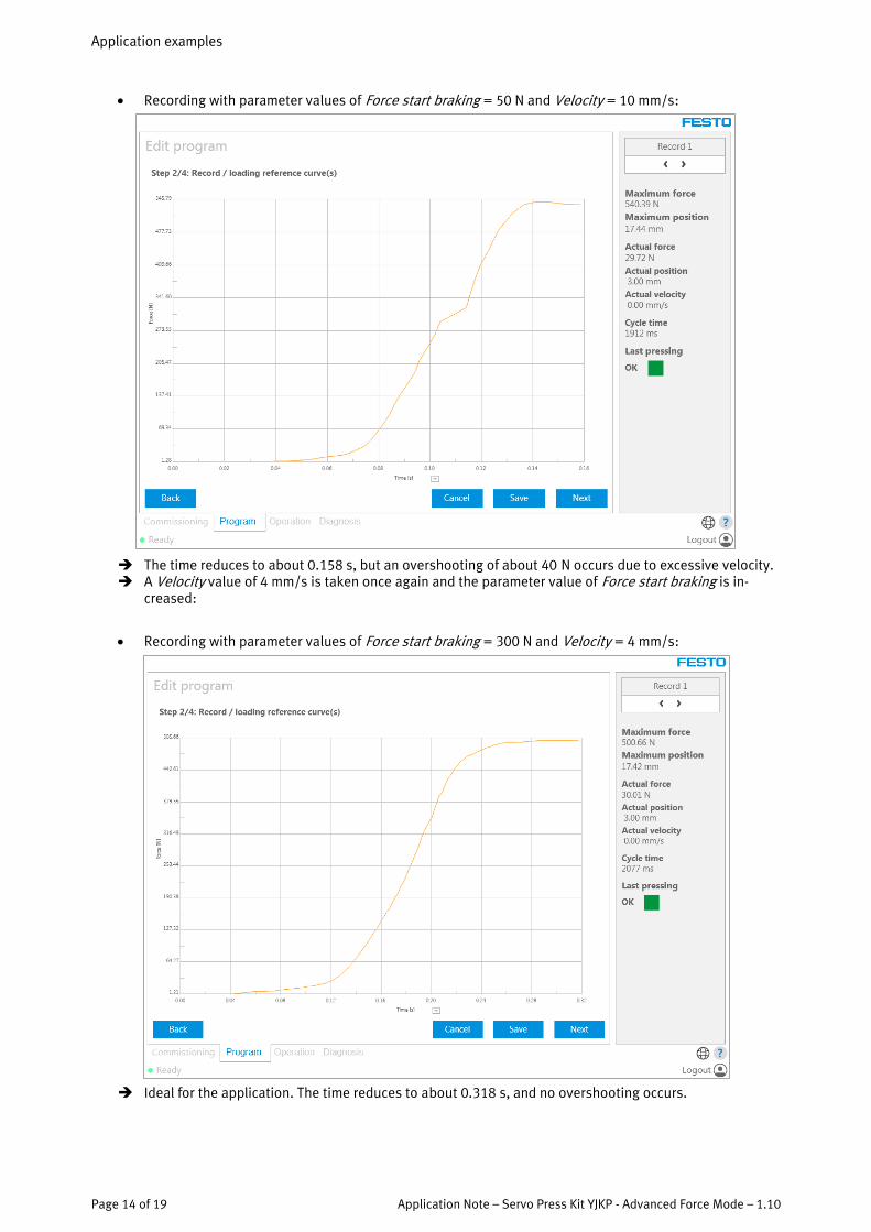
• Recording with parameter values of Force start braking = 50 N and Velocity = 10 mm/s:
The time reduces to about 0.158 s, but an overshooting of about 40 N occurs due to excessive velocity. A Velocity value of 4 mm/s is taken once again and the parameter value of Force start braking is in-
creased:
• Recording with parameter values of Force start braking = 300 N and Velocity = 4 mm/s:
Ideal for the application. The time reduces to about 0.318 s, and no overshooting occurs.

Application examples
Application Note – Servo Press Kit YJKP - Advanced Force Mode 1.10 Page 15 of 19
• Recording with parameter values of Force start braking = 400 N and Velocity = 4 mm/s:
The time reduces to about 0.258 s. This is unsuitable as an overshooting of about 16 N occurs.
4.2 Creating an evaluation method
It is possible to use an evaluation method in the force-position diagram or in the force-time diagram.
To monitor whether the target force has been reached, the following example takes the force-time diagram and applies the "Window" evaluation method:
Using the window, it is possible to monitor whether 500 N are reached and whether an overshoot-
ing with a tolerance of 2% of the target force (= 510 N) is maintained.
Additional evaluation methods can be added and, if necessary, the parameters can be optimised.

Application examples
Page 16 of 19 Application Note – Servo Press Kit YJKP - Advanced Force Mode – 1.10
4.3 Comparison of the advanced force mode with the force mode
The same structure and requirements are used as in the previous Chapter 4.1.1.
Advanced force mode:
The determined optimum parameter values (Force start braking = 300 N, Velocity = 4 mm/s) from the previous Chapter 4.1.4 lead to the following curve:
The step time amounts to about 0.318 s, the cycle time amounts to about 2.077 s and no overshooting
occurs.

Application examples
Application Note – Servo Press Kit YJKP - Advanced Force Mode 1.10 Page 17 of 19
Force mode:
In the following, the parameters for force mode are determined. Here, only the velocity can be changed.
Recording with the same Velocity value (= 4 mm/s) as in advanced force mode:
A similar step time as for advanced force mode of about 300 ms is reached, but an overshooting of
140 N occurs. The overshooting must be strongly reduced.
Recording at a parameter value of Velocity = 1 mm/s:
The step time is about 400 ms longer than in the case of advanced force mode is reached, and an
overshooting of 33 N occurs. The overshooting must be reduced.

Application examples
Page 18 of 19 Application Note – Servo Press Kit YJKP - Advanced Force Mode – 1.10
Recording at a parameter value of Velocity = 0.35 mm/s:
The cycle time amounts to about 3.5 s, the stepping time amounts to about 1,800 ms and an over-
shooting of 6 N occurs. The target force reached therefore lies within the tolerance range of the ap-plication. This is the optimum setting for force mode.
In order for the same requirements on the precision of the joining procedure are reached, the force mode re-quires a step time of about 1,800 ms and the advanced force mode requires a step time of about 300 ms. The advanced force mode is therefore about 6 times faster than force mode.
With the velocity switching function of advanced force mode, the cycle time can be reduced even further.
Application examples
Application Note – Servo Press Kit YJKP - Advanced Force Mode 1.10 Page 19 of 19
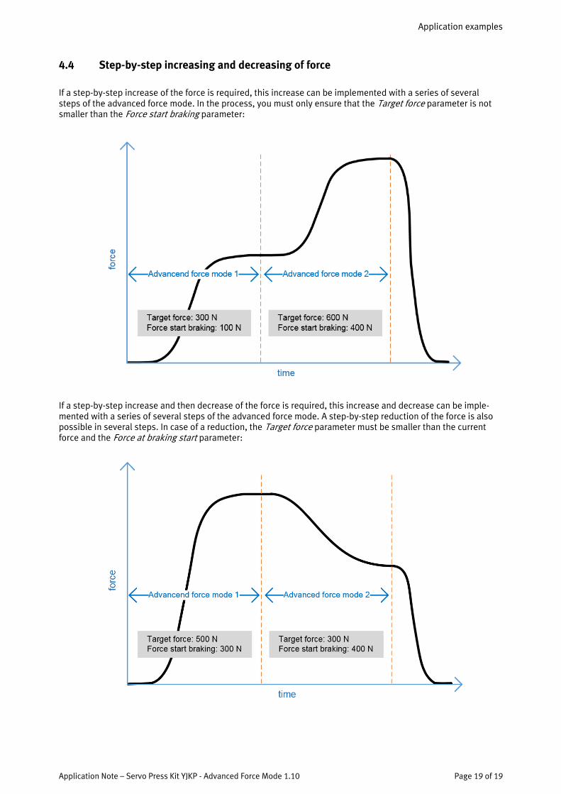
4.4 Step-by-step increasing and decreasing of force
If a step-by-step increase of the force is required, this increase can be implemented with a series of several steps of the advanced force mode. In the process, you must only ensure that the Target force parameter is not smaller than the Force start braking parameter:
If a step-by-step increase and then decrease of the force is required, this increase and decrease can be imple-mented with a series of several steps of the advanced force mode. A step-by-step reduction of the force is also possible in several steps. In case of a reduction, the Target force parameter must be smaller than the current force and the Force at braking start parameter: