session three management of functional safety … three: management of functional safety- gaps in...
TRANSCRIPT

Session Three: Management of Functional Safety- Gaps in the Operation Phase
Safety Control Systems Conference 2015 1
Session Three
Management of Functional Safety – Gaps in the Operation Phase
Andy Yam Functional Expert-Safety Systems, Yokogawa Australia Pty. Ltd.
1 Abstract According to the IEC 61511 standard, the purpose of having a Functional Safety Management (FSM) system during the safety lifecycle is to identify the management activities that are necessary to ensure that the functional safety objectives of the safety instrumented system are met. These activities are separate from the health and safety measures in the workplace. As per the safety lifecycle model in this standard, management of functional safety is a requirement throughout the lifecycle of the plant, including during the conceptual, implementation and operational phases. In the ensuing years after the release of the functional safety standards, a lot of emphasis has been placed on meeting the requirements during the conceptual and implementation phases. However, it is equally important that the Safety Instrumented System (SIS) is operated and maintained in compliance with the standards, especially considering that plants typically are operated for up to 30 years as compared to the Conceptual and Realization Phases, which may last a couple of years. This paper looks at some common gaps in operation and the strategies and activities required for compliance.
2 Standards IEC 61511 Safety Lifecycle (SLC) clearly shows the requirement for verification at every phase of the safety lifecycle. More importantly, is the requirement for management of functional safety throughout the whole SLC, covering all the phases from Phase 1 Hazards and Risks Analysis all the way to Phase 8 Decommissioning. That implies the following must be in place when the plant starts up – all operations and maintenance procedures, competent operations and maintenance staff, SIS performance monitoring systems.

Session Three: Management of Functional Safety- Gaps in the Operation Phase
Safety Control Systems Conference 2015 2
Figure 1 IEC 61511 Safety Lifecycle Model
The same can be said of the IEC 61508. Consider selected clauses from Part 1 here: Clause 6.2.121 states that “individuals who have responsibility for one or more phases of the safety lifecycle shall, in respect of those phases, specify all management and technical activities to ensure the achievement, demonstration and maintenance of FS.” Clause 7.15, titled “Overall operation, maintenance and repair”, specifies that “the objective is to ensure the functional safety of the E/E/PE safety-related systems is maintained to the specified level.” That implies again there is work to do to ensure that after the SIS is installed and the plant is running, the safety integrity of the SIS is maintained to the designed level.
3 Current Focus Since the release of the IEC functional safety standards, a lot of focus has been placed on the conceptual and implementation phases of the safety lifecycle. According to a study of systematic and human failures conducted by the Health and Safety Executive UK (Figure 2), up to 65% of the failures studied occurred during the design, engineering, installation and commissioning phases. Hence, in a way, one can understand why there has been such emphasis on the pre-operation phases of the safety lifecycle (SLC).
1 Functional Safety of Electrical/Electronic/Programmable Electronic Systems IEC 61508 Ed. 2

Session Three: Management of Functional Safety- Gaps in the Operation Phase
Safety Control Systems Conference 2015 3
Figure 2 Study of Systematic and Human Failures - HSE UK
In the projects that the writer has been involved in, where there has been a requirement for safety systems, be they in the Oil and Gas, Petrochemical or in the Power industry, it is observed that there is much effort placed on the conceptual and implementation phases of the safety lifecycle. End-users are fully aware of the need to carry out a hazards and risk analysis, identify Safety Instrumented Functions (SIFs) and to allocate Safety Integrity Level (SIL) targets to these SIFs. They select suitably certified equipment for the SIF hardware, including sensors, logic solvers, final elements and everything else in the safety loop. SIL Verification is carry out during the design phase to ensure the designed SIFs meet their respective SIL targets. However, whether as much effort is spent on the operational and maintenance phase, after the commissioning teams demobilize from site, remains a moot point. This can be further confirmed, on a global level, if we look at the changes made to IEC 61508 for Edition 2 after gaining experience from the first 10 years since Edition 1 was released. The major changes included many important improvements ranging from making competency requirements normative rather than informative, defining new hardware and systematic compliance routes and many other clauses in Design and Engineering, to consideration of security issues. Out of these, just 2 small changes were made to the Operations and Maintenance Phase - one related to taking a single (HFT=0) device offline and another regarding procedures for faults in the SIS.
4 Where the Problem starts When should Project Managers start preparing operation and maintenance regimes in safety related project? The IEC 61508 Safety Lifecycle Cycle clearly shows that we need to carry out “overall operation and maintenance planning” in parallel with our system design and realization (Figure 3). A whole subsection (clause 7.7 IEC 61508-1) is dedicated to this activity.

Session Three: Management of Functional Safety- Gaps in the Operation Phase
Safety Control Systems Conference 2015 4
Very often, the problem is that stakeholders do not include this crucial activity into the overall project scheduling and resourcing. Project Managers need to ensure that priority goes into listing out all the detailed tasks required for this activity and to include these tasks in the overall project planning. On a corporate level, Project Managers could work closely with Operations Management to get an early commitment from Operations, with the aim to include specific statements on process safety in the overall Health, Safety and Environment Policy in the plant. This would help put in place guiding principles and focus attention on Process Safety and Risk Management of which Functional Safety is an integral part. A Functional Safety Manager could be appointed early to champion Functional Safety planning and administration matters.
Figure 3 IEC61508 Safety Lifecycle Diagram
Both the functional safety standards IEC 61508 and IEC 61511 stipulate a final checkpoint, in the form of the final functional safety assessment, prior to the plant coming online. The IEC61511 standard recommends Functional Safety Assessments be carried out at the 5 stages (see Figure 4) with a minimum of one compulsory assessment at Stage 3.

Session Three: Management of Functional Safety- Gaps in the Operation Phase
Safety Control Systems Conference 2015 5
Figure 4 IEC 61511 Functional Safety Assessment Stages
This final safety assessment includes, amongst other things, a scrutiny of the plant readiness for operations. The adequacy of procedures for operation and maintenance of the SIS, and training for the plant personnel to operate and maintain the safety of the SIS is assessed one last time prior to plant start-up. However, it is very rare for a Functional Safety Assessor to be given the authority or having the inclination to put a HOLD to the project momentum in case of any identified shortcomings. Worse still, one wonders if this critical final assessment actually takes place as required in the standards.

Session Three: Management of Functional Safety- Gaps in the Operation Phase
Safety Control Systems Conference 2015 6
5 Unwanted Scenarios Four scenarios are described below in new or recently upgraded plants faced with newly commissioned SISs. This is in the interest of learning valuable lessons about the gaps in Operation and Maintenance in these plants.
5.1 Unwanted Scenario 1 – Where are we? “We know we have some obligation with respect to maintaining our SIS but we do not know what we have to do to maintain our SIS. We can’t find any HAZOPs report, SIL Assignment Report nor is there an SRS. What should we do?” Scenario 1 is indicative of poor project management in the original SIS project. There is no traceability in the document trail and the plant is ‘stuck’ with a SIS which no one knows how to maintain as there is no knowledge of the safety requirements and the designed SIFs. The only way out is to go back to the relevant lifecycle phase and work through the safety lifecycle to a point where the system can be re-validated. One would hope no safety related project ends up like this.
5.2 Unwanted Scenario 2 – Project Completed “We have successfully commissioned the SIS and our plant is running fine. Congratulations, we have put in place a state-of-the-art protection system which is certified for applications up to SIL3. We have complied with the standards in all design and engineering activities. Project successfully completed. We need to hand-over to production to maintain the SIS.” Scenario 2 is typical of a lot of projects in the industry, unfortunately, where the main focus is to meet the critical end-date, which invariably is plant start-up. In the drive to achieve the target start-up date, operation and maintenance issues are not considered a high priority and kept for ‘later’. As mentioned previously, the project work breakdown should include operation and maintenance planning activities and these need to be scheduled into the project schedule.
5.3 Unwanted Scenario 3 – Struggling with Prior-Use Evidence “In our existing plant, we need to justify the SIF design but have no failure rate data for the installed devices other than our maintenance logs of plant failures. These logs are not very complete as our maintenance department has not recorded how each device failed and we cannot be sure they have been recording every failure diligently.” Scenario 3 explains why Route 2H is seldom used for hardware compliance. Proven-in-use evidence requires accurate collection and recording of plant failures for such data to be valid, and the statistical confidence level of such device failure data shall be at least 90%. Similarly, for any revision of target integrity levels based on improved field failure rates, in the first instance, a formal data collection system needs to be put in place.

Session Three: Management of Functional Safety- Gaps in the Operation Phase
Safety Control Systems Conference 2015 7
5.4 Unwanted Scenario 4 – We prefer the old system. “Our operators could troubleshoot easily before with the old system. We have a plant trip and need support to start up the plant. Even though the SOE shows the trip was due to Pre-refractioner Column Low Flow, we suspect it’s due to system failure.” Scenario 4 is an obvious illustration of unfamiliarity on the part of the plant engineers with the new SIS and a lack of confidence to troubleshoot using the new SIS. Untrained SIS personnel can mean assumptions or credit taken during LOPA (operator action) and SIL verification (MTTR) are no longer valid but more critically, it can lead to unsafe situations, where human and systematic failures introduced by untrained personnel prevent a SIF from performing its safe action.
6 Planning for Operation and Maintenance Ideally, this planning is carried out as early as possible in the project, so that sufficient time remains to iron out any issues. All Risk Management and SIS related activities during Operation must be identified. Priority should be given to setting up an effective organization and getting competency of personnel up to the required level. In some plants, Operator Training Simulators need to be prepared in parallel and delivered before the main project, to ensure that the plant operators have sufficient practice and are equipped with the knowledge to efficiently and confidently manage the process using the new technology put in front of them. Critically, once the plant comes online, safe operator action is required from the first day of operation. The next priority should be on clear and concise operation and maintenance procedures.
6.1 Risk Management and SIS Related Activities during Operation and Maintenance A good starting point is to identify all required risk management and SIS related activities in the plant. These activities can be broadly classified as those - For operating the SIS during normal and abnormal situations - Related to SIS Maintenance and Repair - Which are required to maintain the SIS integrity eg proof testing - For preventing an unsafe state during maintenance. For Eg. Precautions
required in case of use of Maintenance Overrides/Bypasses - Concerning Information gathering - For managing changes and modifications - For SIS performance monitoring - periodic review of protection measures and procedures - For identifying any unforseen or new hazards eg. Redoing HAZOPs Planning should also include other related activities like quality assurance (audits, reassessment) and resource management (personnel selection, competency assessment, training etc).

Session Three: Management of Functional Safety- Gaps in the Operation Phase
Safety Control Systems Conference 2015 8
6.2 Personnel In the competence model described by the HSE, UK2, activities that can be performed by an individual or a team are grouped together to be carried out under a ‘role’. Competency criteria to carry out each role is defined by the organization. Departments and individuals responsible for identified operation and maintenance roles should be assigned at an early stage, to ensure that each safety-related role is filled by personnel with relevant qualifications, skills, knowledge and capability. For example, the operator should, on top of his other plant control duties, have a good understanding of - fundamental principles of functional safety - plant hazards being protected against - details of the safety instrumented functions from ‘pipe-to-pipe’ - manual actions including Maintenance Override and emergency shutdowns - how to respond to alarms Performing competency assessments early allows any shortcoming to be identified and addressed in a timely fashion. Where training alone is insufficient, a reassignment of the personnel may have to be re-considered. Sometimes the whole staffing strategy may have to be re-considered. For example, the end-user may use vendor specialist support thence allowing plant personnel bedding-in time to gain confidence and sufficient practical experience to be able to operate the new technology competently. Ideally, key personnel are also involved in the planning and preparation towards plant operation and maintenance in their respective areas, as they may contribute valuable input from their practical experience.
6.3 Documents and Information from Design All SIS related requirement and design documents important for the operation and maintenance of the SIS are required to be transferred from the Project team. These include latest versions of: - HAZOPs Report - SIL Selection Report - SRS including Safety Integrity and Functional Requirements - SIL Verification - SIS Design As-built documents - Test and Validation Records, including any management of change
documents These documents should be kept updated throughout the lifetime of the SIS. The SIL Verification report in conjunction with the SRS provide details of the proof test frequencies required to maintain the SIS safety integrity. Other documents like - Vendor Specific Operation and Maintenance Manuals - Safety Manuals of SIS devices
2 Managing Competence for Safety-related Systems, HSE UK

Session Three: Management of Functional Safety- Gaps in the Operation Phase
Safety Control Systems Conference 2015 9
must be provided and referred to for maintenance activities, as these specify specific application constraints and required periodic testing.
6.4 Procedures to prepare for Operating/Maintaining the SIS All modes of operation of the plant including start-up, shutdown and normal operation, need to be considered in describing the operation and maintenance activities of the SIS. The following areas require particular attention in developing the SIS procedures:
6.4.1 Management of Maintenance Override/Bypass/Inhibits
The procedure for implementing and removing a bypass shall be clearly defined and any restriction during use highlighted to avoid systematic failures being introduced. Any facility for maintenance override or bypass shall be secured by strict procedural control (eg. Management approval), in combination with secured access (eg. Password or key-switch protection). Consider the situation where one transmitter, out of a pair voted 1oo2, has failed and the failure is detected by the transmitter diagnostics. The SIS voting degrades to 1oo1. The maintenance team then by mistake, overrides the good transmitter from the control room and remove the failed one for repairs. If the replacement part takes weeks to arrive, that means that the affected SIF has been effectively masked by the wrong override action for potentially the duration of the repair period. Therefore, the process of activating the bypass must go through a clear step-by-step procedure, where each action is taken is verified to ensure there is no error. Communication between shifts regarding any activated bypass shall be formalised, to alert all parties of the degraded SIF and to avoid systematic errors being introduced, with change of shifts. A log must be kept of all instances of bypasses, with details of requestor, approver, time and date of activation and deactivation, field device affected, and purpose of the bypass. Duration of signal bypass should be limited, with safeguards in place in case the maintenance override extends beyond the pre-defined period. These safeguards could be in the form of requirement for approval by higher management and pre-warning alarm prior to expiry of the bypass period. Verification of removal of the signal override should be part of procedure. SIS signal forcing is not allowed during operation, even though it is commonly used during site acceptance testing.
6.4.2 Procedures for Proof Testing and Inspections
The starting point to prepare the framework for proof testing would be an ‘as-built’ database of all safety related devices. Each device should be clearly identified with a unique tag and the database should include details like SIF number, trip set-point, device model and version, proof test interval and manufacturer instructions regarding target failure rate, how to proof-test etc.

Session Three: Management of Functional Safety- Gaps in the Operation Phase
Safety Control Systems Conference 2015 10
The method to proof test each device type shall be defined in clear steps to eliminate any uncertainty in the field when the technician carries out the proof testing. The proof test technique should be based on vendors’ manuals to ensure correct and safe testing. Unclear or incorrect test procedures can lead to introduction of systematic errors or a lower test coverage than claimed. Failures discovered during proof-testing shall be repaired immediately or within the repair time used in SIL calculations, as the concept of taking credit for proof testing is on the premise that detected dangerous failures are repaired to bring the SIF back to ‘as new’ state. Specific instructions on how to place the tested device back into service and to validate that this has been correctly done is required to prevent errors being introduced. For example, if a technician went to calibrate a pressure transmitter in the field, he first isolates the transmitter from the process using a 3-way test valve, and then connect the calibrator to the test point to inject pressure over the range required for calibration. Satisfying himself that the transmitter is accurate over the operating range, he then proceeds to bleed the pressure from the test line and disconnects the calibrator from the test point. If he misses the step to turn the three-way valve back to “in service” the transmitter will now measure atmospheric rather than process pressure. Standard templates for recording proof testing shall be prepared and these should include details like device tag, serial number, test procedure, person conducting the test, any bypass activated, test results and record of having placing the system back online.
6.4.3 Management of SIS Failures
Actions in response to SIS failures shall be defined. These actions include - any manual action required to maintain the risk reduction while the SIS is
being repaired - efficient trouble-shooting, - correct and safe repair procedure - re-validation after repair Clear and precise procedures shall be designed to ensure that no systematic failure is introduced in the repair process. SIS failures are to be recorded with details of device ID, location, type of device, mode of failure (failed-safe, failed-dangerous), related SIF(s), cause of failure, how failure was detected- whether during a Plant trip or failure to trip, during periodic inspection and testing, during normal operation or otherwise.
6.4.4 Verification of Actions in SIS Operations and Maintenance As for other phases in the SIS SLC, activities in the Operations Phase including activation and removal of maintenance overrides, repair and testing need to include verification, to check for correctness and adherence to defined procedures. Verification activities can be made more structured with the use of check-sheets to ensure all key areas have been covered. Record of verification is to be kept for traceability.

Session Three: Management of Functional Safety- Gaps in the Operation Phase
Safety Control Systems Conference 2015 11
6.4.5 Information Collection Key data regarding the SIS is required to be collected. These include information on SIS failures, proof-test and partial stroke test results; and information on plant trips, whether scheduled, spurious or due to genuine process demand on the SIS action. Formal data collection methods in accordance with international standards (e.g., IEC 60300-3-2 or ISO 14224) are recommended to be put in place for above data collection. A formal data collection will stand up to legal scrutiny in case of collected data being used to justify a review of SIS targets.
6.4.6 Management of Change Procedure for Modifications
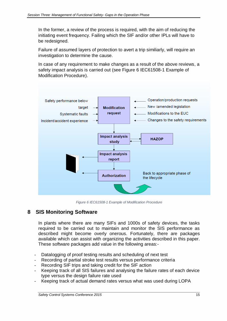
In the event of any requirement to modify the SIS, a management of change procedure shall be followed (see Figure 6 IEC61508-1 Example of Modification Procedure) to ensure that the change is implemented without compromising the capability of the SIS to protect against plant hazards.
6.5 Audits and Re-assessment Allocation shall be made to allow for periodic and independent functional safety audits of the organization for SIS activities. Among the key areas to be covered during such audits, - Adherence to specified procedures - Competency of assigned staff - Documentation - Verifications and reviews - Actual field audit of SIFs Re-assessment is recommended to be carried out after attaining sufficient operating and maintenance experience and is required whenever there is a modification.

Session Three: Management of Functional Safety- Gaps in the Operation Phase
Safety Control Systems Conference 2015 12
7 Operation and Maintenance – Monitoring of SIS Performance Figure 5 SIS Monitoring shows a flow chart for SIS monitoring activities during Operation and Maintenance. The SIS health is monitored by keeping track of key SIS performance indicators and comparing these against design figures.
Figure 5 SIS Monitoring

Session Three: Management of Functional Safety- Gaps in the Operation Phase
Safety Control Systems Conference 2015 13
7.1 SIS safety integrity A good measure of the performance of the SIS is the actual failures of SIS components experienced at site, specifically the dangerous undetected failures experienced. These failures can be revealed during normal operation, proof testing, partial stroke testing, plant trips or scheduled plant shutdowns. Comparing the number of these failures in operation versus their expected failure rate gives an indication of the SIS performance. The SIS’ safety integrity must not be lower than what was expected during design stage. Therefore, if the recorded undetected dangerous failures are higher than the expected no. of failure in the operating period, then there is cause to review the failure rate assumed during the design phase. The expected number of failures Fexp for an identical type of device is given by Equation 1:
Equation 1 Expected Failures
where n = Number of such devices in operation T = Operating period during which devices are tested at least once λDU = Dangerous undetected failure rate assumed in SIF design
Example. There are 1000 Safety Sensor Type X operating in a plant. The vendor safety manual gives λDU of the device as 1.8 E-06/hr. Over a year of operation, these sensors are proof tested every six months, and the number of sensors that had dangerous failures revealed during proof tests was 3. The expected number of dangerous undetected failure over the one year is given by Fexp = 1000x 8760 x 1.8E-06 := 15 (rounded to next lower integer)
Since the actual number of dangerous undetected failures encountered is less than Fexp, one can conclude that the performance of the safety sensor X is within design target.
In the example above the safety sensor type encountered an actual dangerous undetected failure count which was fewer than the expected number of failures based on the actual number of unit-operation hrs. In the case that the encountered dangerous failures are greater than or even close to Fexp, an investigation into the possibility of reducing the failures shall be carried out. A review of the cause analysis of the failures might reveal one of the following root causes which may have been overlooked: - Device is used in an overly harsh environment
Fexp= n x T x λDU

Session Three: Management of Functional Safety- Gaps in the Operation Phase
Safety Control Systems Conference 2015 14
- Device is used outside its specification limits, causing increased failures - Wrong installation - Human factor in operation - Incorrect maintenance causing degradation Corrective action to address the identified cause is required to improve the SIS performance. Where no direct or indirect cause can be found for the higher than expected number of failures, it can be that the assumed λDU is too optimistic. Until further data or findings prove otherwise, it is advisable to add a field factor into the failure rate for calculating PFDavg. Field factor κ is given by
Equation 2 Field Factor
Where Fact is actual number of failures during the same period and Fexp is expected number of failures over an operating period
Equation 3 Failure Rate taking into account Field Factor
Where λ'DU = Device failure rate after taking into account actual field experience. More frequent proof test interval may have to be adopted if particular SIFs, which include the device, fail to meet the SIL target with λ'DU.
7.2 Demand frequency The concepts of risk reduction and SIL rely on estimated demand rates on the
SIS for protection against identified hazards. To check the design intent, the
number of genuine trips or plant shutdowns can be measured against assumed
demand rates.
If it is found that the plant is tripped more frequently than assumed during SIL
Selection, it may show that
- the frequency of initiating events is higher than expected and/or
- Other independent protection layers (IPLs) are not functioning as intended
κ = Fact
Fexp
λ'DU = κ x λDU
Session Three: Management of Functional Safety- Gaps in the Operation Phase
Safety Control Systems Conference 2015 15
In the former, a review of the process is required, with the aim of reducing the
initiating event frequency. Failing which the SIF and/or other IPLs will have to
be redesigned.
Failure of assumed layers of protection to avert a trip similiarly, will require an
investigation to determine the cause.
In case of any requirement to make changes as a result of the above reviews, a
safety impact analysis is carried out (see Figure 6 IEC61508-1 Example of
Modification Procedure).
Figure 6 IEC61508-1 Example of Modification Procedure
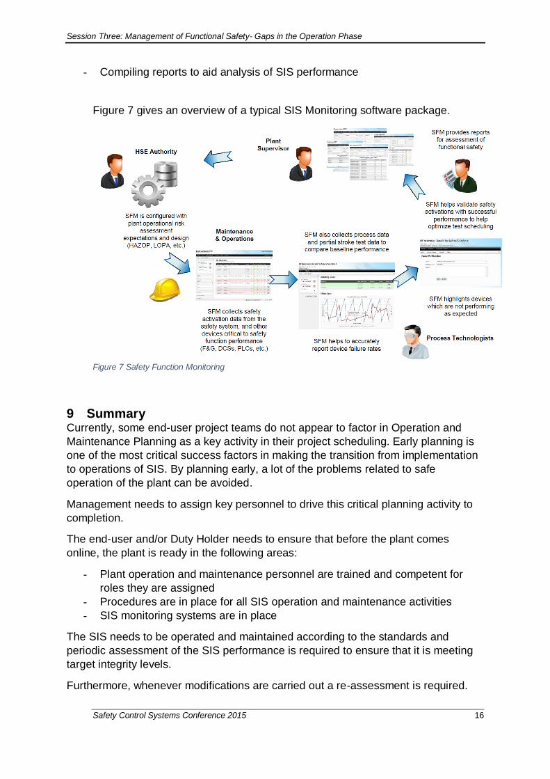
8 SIS Monitoring Software In plants where there are many SIFs and 1000s of safety devices, the tasks required to be carried out to maintain and monitor the SIS performance as described might become overly onerous. Fortunately, there are packages available which can assist with organizing the activities described in this paper. These software packages add value in the following areas:-
- Datalogging of proof testing results and scheduling of next test - Recording of partial stroke test results versus performance criteria - Recording SIF trips and taking credit for the SIF action - Keeping track of all SIS failures and analysing the failure rates of each device
type versus the design failure rate used - Keeping track of actual demand rates versus what was used during LOPA
Session Three: Management of Functional Safety- Gaps in the Operation Phase
Safety Control Systems Conference 2015 16
- Compiling reports to aid analysis of SIS performance Figure 7 gives an overview of a typical SIS Monitoring software package.
Figure 7 Safety Function Monitoring
9 Summary Currently, some end-user project teams do not appear to factor in Operation and
Maintenance Planning as a key activity in their project scheduling. Early planning is
one of the most critical success factors in making the transition from implementation
to operations of SIS. By planning early, a lot of the problems related to safe
operation of the plant can be avoided.
Management needs to assign key personnel to drive this critical planning activity to
completion.
The end-user and/or Duty Holder needs to ensure that before the plant comes
online, the plant is ready in the following areas:
- Plant operation and maintenance personnel are trained and competent for
roles they are assigned
- Procedures are in place for all SIS operation and maintenance activities
- SIS monitoring systems are in place
The SIS needs to be operated and maintained according to the standards and
periodic assessment of the SIS performance is required to ensure that it is meeting
target integrity levels.
Furthermore, whenever modifications are carried out a re-assessment is required.
Session Three: Management of Functional Safety- Gaps in the Operation Phase
Safety Control Systems Conference 2015 17
Functional Safety Audits shall be carried out on the plant for adherence to FSM
procedures.

Session Three: Management of Functional Safety- Gaps in the Operation Phase
Safety Control Systems Conference 2015 18
References: 1. Functional Safety of Electrical/Electronic/Programmable Electronic Safety-
related Systems, IEC 61508 Parts1-7 Edition 2 2. Functional Safety – Safety Instrumented Systems for the Process Industry,
IEC61511 Parts 1-3 Edition 1 3. Managing competence for safety-related systems, HSE UK 2007 4. Application of IEC 61508 and IEC 61511 in the Norwegian Petroleum Industry
No.: 070 Rev 02 Date: October 2004