shapa technical bulletin no · pdf fileshapa technical bulletin no. 12 discharge aids page 1...
TRANSCRIPT

SHAPA Technical Bulletin No. 12
Discharge Aids
Page 1 of 34 August 2007
SHAPA Technical Bulletin No.12
Discharge Aids

SHAPA Technical Bulletin No. 12
Discharge Aids
Page 2 of 34 August 2007
Discharge Aids This bulletin was originally prepared as a paper for the Particulate Solids Group of the
AIChemE by;
Lyn Bates - Ajax Equipment Ltd. (SHAPA member)
Shrikant Dhodapkar - Dow Chemicals
George Klinzing - Pittsburgh University
Introduction
A wide variety of bulk solids are processed and handled throughout industry, from very fine
powders, as pigments, clays, talc, to coarse granules, flakes and fibrous products.
Bulk material, such as agricultural grains, have been stored in silos since the ancient
Egyptian civilisation. Vessels of many shapes and sizes have since been built though a
process of trial and error, to store a huge range of bulk materials in virtually all spheres of
industry. Particle technology has evolved considerably over the last 50 years, to produce a
coherent set of theories and design guidelines for practitioners in the industry, (1). However,
there are many challenging materials whose behavior cannot be easily accommodated by
current theories. For instance, it is difficult to design a reliable storage system based solely
on gravity flow for fibrous, spring-like, wet / moist, stick & tacky, visco-elastic, highly
compressible, caking prone and very fine bulk materials. For these types of materials,
applications where conventional design does not provide an acceptable solution and retrofit
situations where operating difficulties are encountered, discharge aids or discharge systems
are often used to secure discharge and empty the contents of silos
These devices are almost invariably selected based on past industrial experience or by a
process of trial & error. Selection must take into account constraints that are imposed by the
process and the available space. There is usually a significant economic penalty for incorrect
or sub-optimal choice of a discharge system in terms of extended commissioning costs,
production delays and interruptions, loss of output, product wastage, loss of quality,
increased maintenance and manual attention cost.
The objective of this paper is to summarise information on dischargers that are currently
prevalent in industry. An effort is also made to provide guidelines for their selection and
specification as part of an integral design, or for retrofit to overcome operating problems.

SHAPA Technical Bulletin No. 12
Discharge Aids
Page 3 of 34 August 2007
Mined Minerals Chemicals Plastics Agricultural Products Food
Coal Pigments Plastic powders (PE, PP, PET, PVC) Wood Chips & Shavings Flour
Clays Portland Cement Rubbery pellets and crumbs Animal Feeds Bran
Flourspar Detergents Plastic chips and flakes Grains Cereal
Gypsum Carbon Black Rubber chips Diary feed Corn Starch
Perlite Metal Oxides Shredded recycle Dried milk Powdered Sugar
Diatomaceous Earth Calcium Carbonate Soft and tacky pellets Hulls (rice, cottonseed, oat) Chocolate
Talc Herbicides High oil and fat feeds Ground grains
Alumina powder Cellulosic derviates Shredded straws and stalks
Iron Ore Pharmaceutical powders
Lime Sludge
Soda Ash Fertilizers
Bentonite
Phosphates
Table 1. Examples of challenging bulk materials used in various industries

SHAPA Technical Bulletin No. 12
Discharge Aids
Page 4 of 34 August 2007
Background
Discharge aids may be defined as devices that stimulate or improve bulk solids flow out of
bulk storage container. Items may be installed downstream of discharge aids to provide a
means to shut off or regulate the flow of bulk solids. Slide gate valves and feeders are
examples of discharge controllers. A discharge system can either be integrated with the silo
or installed as an add-on, depending on the design and reason for its inclusion. [2].
It is important to distinguish between the basic objectives of discharger aids and those of
feeders to avoid misapplications. The primary purpose of a discharger aid is to promote
flow, not necessarily to regulate it, and without regard to the order of zone discharge. A
feeder, on the other hand, depends on the material flowing reliably to its inlet. Feeders
influence the flow regime developed in the storage container and will not function if flow in
the bin is unreliable. A feeder and its supply hopper are therefore an integral system.
Types of Flow Problems
The more common forms of flow difficulty are concerned with the restriction of flow, either
complete or erratic stoppages, or a delivery rate less than that required. Circumstances also
arise where the discharge rate is in excess of requirements, uncontrollable, in an unsuitable
condition for handling, process or use or is incomplete.
These difficulties arise for a number of different reasons, such as: -
- Arching, where the product forms a blockage over the outlet and flow ceases.
Two basic types of arch can create a stable obstruction over a hopper outlet. One is
that created by the bulk strength of a cohesive material being able to span the
dimension of the opening. The other is when lumps come together to make a
continuous structural across the orifice by virtue of the contact points offering a static
relationship that makes a continuous load path as in a bridge.
- Piping, where material empties from a central core above the outlet up to the surface
level of the stored material but no further product collapses into the empty flow
channel.
- Irregular flow, where the discharge rate is erratic or subject to cyclic variations, that
is not compatible with the specific process requirements of the operation.
- Flushing, a form of uncontrollable flow, generally due to the presence of excess air
or gas in the voids that dilates the bulk material to a weak condition with virtually
zero shear strength.
- Static zones of storage that subsequently offer problems due to deterioration of flow
property or product quality because of extended residence time.
- Residue unable to discharge by gravity.
- Segregation, that leads to flow or processing difficulties or loss of quality.
- Particle attrition causing operation problems, hazards or loss of quality.

SHAPA Technical Bulletin No. 12
Discharge Aids
Page 5 of 34 August 2007
Designing for Reliable Flow
A scientific design based on best practice, measured properties of the bulk material and
knowledge of various special techniques can avoid most of these problems. However, apart
from the awkward nature of some bulk materials, many storage units are constructed on
standard forms that are convenient for manufacture but do not take appropriate account of
the bulk material properties. Whereas these serve well with many materials that have good
flow characteristics, they can fail badly with various fine, damp or lumpy products and
others that are of a poor flow nature or are sensitive to various aspects of bulk storage.
Various types of flow patterns develop in bin/silos, depending on the shape of the
converging section and the particle-wall friction. (3). Of particular interest are ‘Mass Flow’,
where all the contents are in motion during discharge, ‘Expanded Flow’ where contents in
the outlet region are all in motion, but static zones form in higher regions, and ‘Non-Mass
Flow’, where there is no slip of material on the walls of the bin. A Mass Flow pattern has
benefits in providing best conditions for flow through small outlets and avoiding
indeterminate storage periods for products that are time-sensitive. Expanded Flow offers the
flow benefits of Mass Flow, but is not suitable for products that deteriorate with time, unless
the bin is fully emptied before being refilled. Non-Mass Flow bins are adequate for free
flowing products that similarly do not that deteriorate with time, and may even be used with
products that do degrade or exhibit time-dependent problems, provided the bin is fully
emptied every time before these difficulties arise.
The first and most important decision in hopper selection is to choose a flow pattern for
discharge that is compatible with the nature of the bulk material to be stored. Measurement
of contact friction then allows the required wall slope of a chosen shape to be determined for
slip in Mass Flow, or establish ultimate self-clearing in non-mass flow. A design procedure
for testing bulk materials enables an outlet size to be determined that secures reliable flow in
hoppers of different shapes, with circular, square or slot-shaped openings. It is good practice
to first explore the prospects of a design that work by gravity without additional assistance,
as this offers operational simplicity and minimum maintenance.
Salient points to keep in mind are -.
• The 'Angle of repose' is NOT a basis for silo design
• Measurement of the materials flow properties and wall friction angle are basic design
parameters. A 'representative' sample must be obtained and tests conducted in
appropriate process conditions. Note - All 'worst' conditions must be considered.
• Mass flow design results in a more predictable flow pattern and requires a smaller
outlet size compared to a non-mass flow design.
• Selection of the converging bin section shape, cone, pyramid, wedge or chisel, has a
major influence on the design. It is difficult to secure mass flow with a pyramid
shape because product tends to stick in converging corners. Wedge shape is best for
flow, but a feeder is usually required to extract from the whole outlet area.
• The feeder design and hopper interface must not inhibit the required flow pattern
within the silo. A feeder MUST extract product across the entire cross-section of a
hopper outlet to enable Mass Flow.

SHAPA Technical Bulletin No. 12
Discharge Aids
Page 6 of 34 August 2007
Before considering a discharge aid to address a bin/silo flow problem, it is prudent to
examine the bulk material nature and its flow properties in relation to the existing design.
Hopper modifications may provide a more suitable solution, especially if the problem stems
from an unsuitable flow pattern. Such alternatives may comprise: -
Steeper Hopper: Replacing a shallow hopper with a steeper hopper section is the most
positive way to obtain reliable mass flow, if sufficient headroom is available. Replacing the
region near the outlet forms an 'Expanded Flow' construction to secure the flow benefits of
mass flow, but will not elimination ‘dead’ regions of storage in higher regions of the hopper.
Liners and Coatings: It may be practical to reduce wall friction by the use of liners (e.g.
UHMWPE, polished or 2B finish stainless steel or various types of epoxies and plasma
coatings). It is essential that such changes are based on measured values of friction.
Hopper Shape: Replacing a pyramid or conical section with a plane flow hopper, even one
that applies only to a relatively small outlet region, can secure a significant flow benefits.
More involved geometry can secure even better flow benefits, but these require some
specialised expertise.
Flow Inserts: Hopper inserts are fitted for a host of different reasons, [4]. Some are of
proprietary design or require particular expertise but others are relatively simple in principle
and require only limited knowledge of bulk technology. It must be emphasised that any
fitting that is placed within the flow path of a bulk material may be exposed to high forces,
wear and will be responsible for changes to the flow pattern. Detailed consideration must
therefore be given to the security of the item and the effects that will be created.
Flow Aids: The addition of flow aids, for example fumed silica, is sometimes used to reduce
the cohesive strength of difficult to handle products. Similarly, anti-caking, desiccant, anti-
static and lubricating additives are used for various applications.
There remain many circumstances where gravity flow design is not feasible. For such
applications, a discharge system must be used to achieve reliable discharge. For example: -
• Where the poor flow nature of the material requires a larger outlet size than is
compatible with the feeder of choice or the downstream process. Fibrous,
interlocking, spring-like, wet / moist, stick & tacky, visco-elastic, highly
compressible, soft, caking-prone and very fine powders exemplify such materials.
• Uncontrolled variability in the material flow properties makes it difficult to ensure a
reliable design.
• Where current space constraints, usually headroom and especially in retrofit
situations, do not allow the use of steep walled hoppers.
• The discharge rate of the size of hopper outlet needed for reliable flow is either too
high, too low or needs to be controlled to suit subsequent equipment.

SHAPA Technical Bulletin No. 12
Discharge Aids
Page 7 of 34 August 2007
Ideally, the prospect of using a discharge system should be identified at the initial design
stage of storage silos and details appropriately factored into the structure, including stress
calculations and headroom for installation and maintenance. Failure to do so may seriously
impede the choice of initial equipment or seriously limit the options for retrofit. It is good
practice to include some spare headroom, wherever practical.
Classification of Discharge Aids
Reviews of discharge aids are given by Reed, [5] and Woodcock, [6]. They can be broadly
classified into two categories based on the form of flow promoting mechanism employed:
1. Active devices:- These devices can be grouped into three types -
• Pneumatic
• Vibratory
• Mechanical
2. Passive devices:-
• Hopper shape and construction, - plane flow hoppers, hopper design with
one-dimensional convergence (e.g. Diamondback™ hopper), Sigma Two
relaxation, low friction liners.
• Insert systems, - 'Cone-in-Cone, Compaction shields, Inverted cone, 'Hoops
stress cutters', Flow modifiers.
All discharge aids work using one or more of the following principles: -
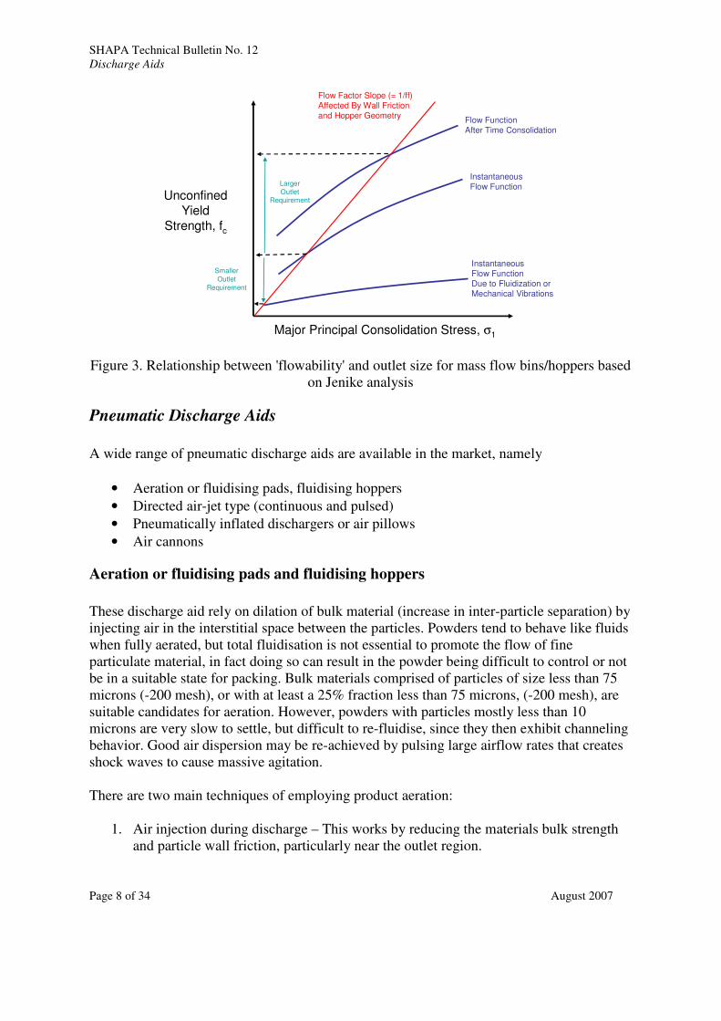
a) Dilate the material to enhance flow. The flow function of dilated material exhibits
significantly lower unconfined yield strength (see Figure 3) thereby making it flow
better. (Air injection may be used to dilate the bulk or inhibit time consolidation due
to settlement).
b) Induce stresses that exceed the strength of the bulk material. (Vibration and
mechanical agitators may be used to deform the bulk).
c) Reduce the friction between particles and the wall of flow channel. (Change the
surface finish to a contact friction of lower value)
d) Modify the flow regime to one more favorable to flow.
e) Alter the bulk material flow properties by additives or surface modifiers. (Inhibit
particle to particle adhesion or 'caking').
SHAPA Technical Bulletin No. 12
Discharge Aids
Page 8 of 34 August 2007
Unconfined
Yield
Strength, fc
Major Principal Consolidation Stress, σ1
InstantaneousFlow Function
Flow FunctionAfter Time Consolidation
Flow Factor Slope (= 1/ff)Affected By Wall Friction and Hopper Geometry
Larger
OutletRequirement
InstantaneousFlow FunctionDue to Fluidization orMechanical Vibrations
Smaller
Outlet
Requirement
Figure 3. Relationship between 'flowability' and outlet size for mass flow bins/hoppers based
on Jenike analysis
Pneumatic Discharge Aids
A wide range of pneumatic discharge aids are available in the market, namely
• Aeration or fluidising pads, fluidising hoppers
• Directed air-jet type (continuous and pulsed)
• Pneumatically inflated dischargers or air pillows
• Air cannons
Aeration or fluidising pads and fluidising hoppers
These discharge aid rely on dilation of bulk material (increase in inter-particle separation) by
injecting air in the interstitial space between the particles. Powders tend to behave like fluids
when fully aerated, but total fluidisation is not essential to promote the flow of fine
particulate material, in fact doing so can result in the powder being difficult to control or not
be in a suitable state for packing. Bulk materials comprised of particles of size less than 75
microns (-200 mesh), or with at least a 25% fraction less than 75 microns, (-200 mesh), are
suitable candidates for aeration. However, powders with particles mostly less than 10
microns are very slow to settle, but difficult to re-fluidise, since they then exhibit channeling
behavior. Good air dispersion may be re-achieved by pulsing large airflow rates that creates
shock waves to cause massive agitation.
There are two main techniques of employing product aeration:
1. Air injection during discharge – This works by reducing the materials bulk strength
and particle wall friction, particularly near the outlet region.

SHAPA Technical Bulletin No. 12
Discharge Aids
Page 9 of 34 August 2007
2. Continuous air injection during storage – This works by inhibiting de-aeration and
the gain of bulk strength of the whole mass due to time settlement.
It should be determined whether the bulk material has a tendency to flush/flood or flow
uncontrollably in fluidised state. In such cases, option #2 is more suitable. The amount of air
required to avoid high strength gain of fine powders due to time settlement is very small, but
the technique is not appropriate for products that rapidly de-aerate (particle size greater than
200 microns).
Excessive fluidisation can result in bubbling and the elutriation of fines. It can also aggravate
the segregation of coarse and fine fractions within the hopper.
Aeration or fluidisation pads are easily mounted on existing hoppers as retrofits (Figure 4).
Sintered media, multi-layer metal mesh or woven media is typically used as air distributor.
Uniform air distribution is achieved by maintaining a large pressure drop across the media.
The air consumption is typically 10 ft3/min per square foot of pad area. These inject air only
when discharge is required. They generate a pressure differential between the injection pint
and the hopper outlet, providing both a driving force and a supply of air to satisfy the void
demand of bulk expansion for flow.
Bulk control can be achieved by use of an aeration pad that covers the whole container base.
Dilatation of the bulk improves the materials ‘flowability’ by reducing both wall friction and
inter-particle cohesion. Activation of the entire hopper section allows a shallow hopper
design to be employed (Figure 5). This may be supplied with a low, controlled-volume
injection during storage, to stabalise the flow condition whilst the material is static, and
increase the degree of aeration by injecting a higher rate of air for discharge. It is critical to
supply oil free, clean and dry air for aeration to avoid product contamination. Appropriate
arrangements must also be made to exhaust excess air and contain entrained dust at the top
of the bin/silo.
Directed air jets
Directed jets can be effective in using the kinetic energy of air-jets to dislodge material from
surrounding hopper wall and provide better gas dispersion through turbulence generation
(Figure 4). The effective radius of these jets is limited to 1- 2 feet. Therefore, the jets must
be placed in effective locations or multiple units need to be installed on the hopper wall to
avoid dead zones. These jets can be timed and pulsed to minimise gas consumption. It is
critical to supply oil free, clean and dry air to avoid contamination and prevent plugging of
fine nozzles.
The crucial flow region for discharge is that near the outlet, because the smaller span at this
location is the most likely place for stoppages to form. Clearing this region, or part of the
periphery of the orifice, is equivalent to having a larger opening that can be sufficient for the
remaining contents to discharge.

SHAPA Technical Bulletin No. 12
Discharge Aids
Page 10 of 34 August 2007
AerationPads
Fluidizing
Directional JetsAeration
Pads
Fluidizing
Directional Jets
Figure 4. Aeration or fluidisation discharge aids
Aeration FlowAeration Flow
Figure 5. Fluidising hopper
SHAPA Technical Bulletin No. 12
Discharge Aids
Page 11 of 34 August 2007
Inflatable
Pads
Uninflated
Inflatable
Pads
Inflated
Inflatable
Pads
Uninflated
Inflatable
Pads
Inflated
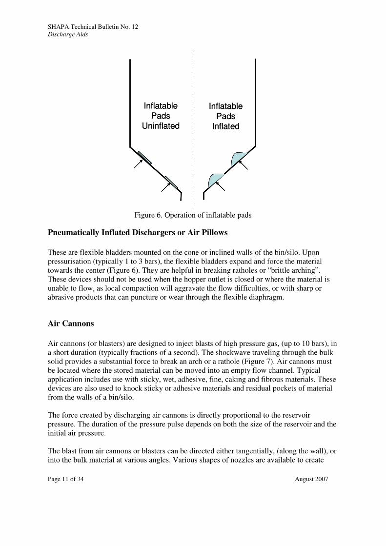
Figure 6. Operation of inflatable pads
Pneumatically Inflated Dischargers or Air Pillows
These are flexible bladders mounted on the cone or inclined walls of the bin/silo. Upon
pressurisation (typically 1 to 3 bars), the flexible bladders expand and force the material
towards the center (Figure 6). They are helpful in breaking ratholes or “brittle arching”.
These devices should not be used when the hopper outlet is closed or where the material is
unable to flow, as local compaction will aggravate the flow difficulties, or with sharp or
abrasive products that can puncture or wear through the flexible diaphragm.
Air Cannons
Air cannons (or blasters) are designed to inject blasts of high pressure gas, (up to 10 bars), in
a short duration (typically fractions of a second). The shockwave traveling through the bulk
solid provides a substantial force to break an arch or a rathole (Figure 7). Air cannons must
be located where the stored material can be moved into an empty flow channel. Typical
application includes use with sticky, wet, adhesive, fine, caking and fibrous materials. These
devices are also used to knock sticky or adhesive materials and residual pockets of material
from the walls of a bin/silo.
The force created by discharging air cannons is directly proportional to the reservoir
pressure. The duration of the pressure pulse depends on both the size of the reservoir and the
initial air pressure.
The blast from air cannons or blasters can be directed either tangentially, (along the wall), or
into the bulk material at various angles. Various shapes of nozzles are available to create

SHAPA Technical Bulletin No. 12
Discharge Aids
Page 12 of 34 August 2007
different dispersion patterns. When operating multiple air cannons, those at the bottom
should be fired first, and the other moving progressively upwards at regular intervals. These
devices should not be used for continuous operation. They are most useful for restarting flow
after long downtime, after a process upset or for terminally clearing the bin after gravity
flow has cleared what will discharge of its own accord.
Every blast causes a reactionary force on the silo wall, so reinforcement of walls near the
blasters fittings must be considered, especially for retrofit situations. Large chunks of caked
or consolidated material may be dislodged from a wall, arch or rathole, to generate
significant impact stresses within the silo. The silo and any associated equipment must
accommodate such conditions.
Figure 7. Air Cannon or air blasters
Vibratory Discharge Aids
Metal bars, mallets and sledge hammers are primitive discharge aids that are commonly
found in solids handling plants. Unsightly deformations and dents, ('hammer rash'), is very
commonly seen on hoppers that are used to handle difficult flow products. While the practice
of mechanical vibrations is old, research on pressure wave propagation in within bulk
materials and the effect of vibrations on flowability is limited and of mixed effect, [7].
The information provided here is a combination of fundamental research, empirical
knowledge and best practices based on experience.
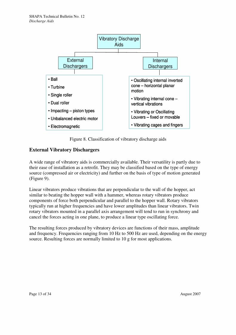
Vibratory discharge aids can be attached externally to the shell of a bin/silo as near as
practical to the outlet or attached to elements/internals directly in the path of material flow
(see Figure 8). These devices are used to address flow problems (arching, bridging or
ratholing) or incomplete material withdrawal due sticking on hopper walls.
SHAPA Technical Bulletin No. 12
Discharge Aids
Page 13 of 34 August 2007
Vibratory Discharge
Aids
External
DischargersInternal
Dischargers
• Ball
• Turbine
• Single roller
• Dual roller
• Impacting – piston types
• Unbalanced electric motor
• Electromagnetic
• Oscillating internal inverted cone – horizontal planar
motion
• Vibrating internal cone –
vertical vibrations
• Vibrating or Oscillating
Louvers – fixed or movable
• Vibrating cages and fingers
Figure 8. Classification of vibratory discharge aids
External Vibratory Dischargers
A wide range of vibratory aids is commercially available. Their versatility is partly due to
their ease of installation as a retrofit. They may be classified based on the type of energy
source (compressed air or electricity) and further on the basis of type of motion generated
(Figure 9).
Linear vibrators produce vibrations that are perpendicular to the wall of the hopper, act
similar to beating the hopper wall with a hammer, whereas rotary vibrators produce
components of force both perpendicular and parallel to the hopper wall. Rotary vibrators
typically run at higher frequencies and have lower amplitudes than linear vibrators. Twin
rotary vibrators mounted in a parallel axis arrangement will tend to run in synchrony and
cancel the forces acting in one plane, to produce a linear type oscillating force.
The resulting forces produced by vibratory devices are functions of their mass, amplitude
and frequency. Frequencies ranging from 10 Hz to 500 Hz are used, depending on the energy
source. Resulting forces are normally limited to 10 g for most applications.

SHAPA Technical Bulletin No. 12
Discharge Aids
Page 14 of 34 August 2007
Figure 9. Classification of external vibratory discharge aids
A useful formula [5] relating peak acceleration (g force) to frequency and amplitude is given
below:
'g' force = 0.1022 x amplitude (inches) x frequency (cycles / sec)
Air driven devices need a lubricated, compressed air supply. The frequency, amplitude and
air consumption are proportional to the supply pressure.
Selection of Vibration Type Based on Application
Linear versus Rotary:
Rotary vibrators are recommended for dry, cohesive products that tend arch or form ratholes.
These types of vibrators are mounted on hopper walls with rigid mounting techniques.
Linear impacting and non-impacting vibrators are used for sticky or wet products. Linear
vibrators are most effective when the hopper walls can flex to some extent. There is
however, a significant overlap in the application uses of rotary and linear vibrators.
Acceptable noise levels in the process area may inhibit the type of vibrator that can be used.
Vibrators should never be run with the discharge valve closed and material is in the hopper
as it is likely to result in severe compaction of the product, especially with a fine powder.
Rotary vibrators may incur resonant transitions during startup and as they more slowly run
down, so may not be suitable for applications where frequent on/off cycling is required.
External Vibratory Discharge Aids
Air Driven Electric Driven
Rotary Linear Rotary Linear
• Ball
• Turbine
• Single roller
• Dual roller
• Continuous impacting (piston)
• Continuous non-impacting (piston)
• Single impacting (piston)
• Electric motor unbalanced load
• Electromagnetic

SHAPA Technical Bulletin No. 12
Discharge Aids
Page 15 of 34 August 2007
Frequency and Amplitude:
The force imparted by a vibrator is a function of its frequency and amplitude. The
frequencies may range from (10 Hz to 500 Hz) and amplitudes may range from 0.01 inches
to 0.5 inches.
Electromagnetic and linear (piston type) vibrators are generally capable of producing
frequencies in the range of 20 to 120 Hz. Rotary (electric) type vibrators operate between 10
to 60 Hz. Very high frequencies, ranging from 100 to 500 Hz, are generated by air operated
roller, ball or turbine type vibrators.
Table 2. Selection of vibrations based on application
Type of Vibration Application
Low Frequency (<30 Hz) – High
Amplitude Vibrations
Coarse or large particles, material sticking
to wall, electrostatic problem, wet materials
Medium to High Frequency (30 Hz to 60
Hz) and Low Amplitude
Compacting materials, discharge of fine
dry powders, reduces wall friction to create
mass flow
Very High Frequency (> 60 Hz) and Low
Amplitude
Hopper cleaning, chute flow, de-aeration,
discharge of fine dry powders
Force Requirement:
A rule of thumb often quoted in the industry is to – “Use 1 lb. of force for every 10 lb. of dry
material in the slope portion of the bin”. This is a good starting point. Higher level of force is
required for bins with thick walls (pressure vessels) or materials that absorb vibrations (e.g.
rubber crumbs, soft plastic pellets).
Installation of Vibrators
Proper Mounting:
Improper mounting of vibrators can result in fatigue and failure of hopper wall or the mount
itself thereby resulting in safety incidents. Most vendors agree on the following guidelines
for installation:
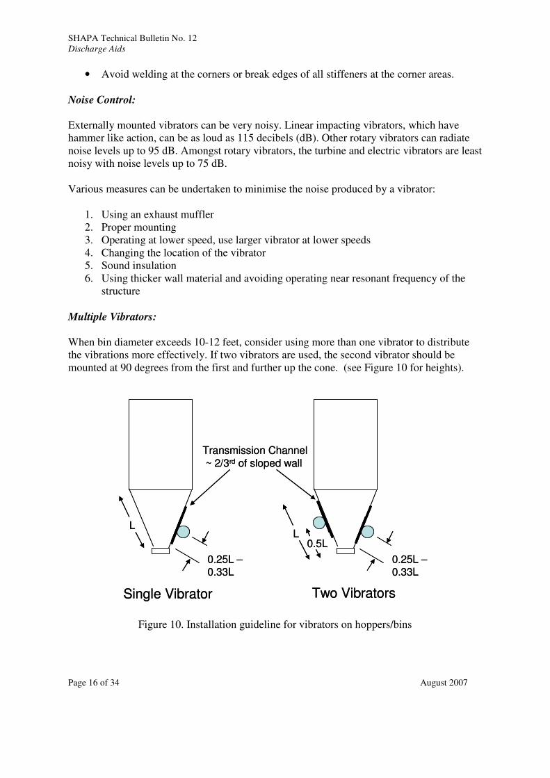
• The transmission channel (see Figure 10) should be approximately 2/3rd
of the length
of the sloped wall
• Always use stitch weld to mount the transmission channel or a stiffener plate to the
hopper wall. A stitch weld of one to two inches with an equal spacing between the
welds is recommended. Leave the ends free of weld. Continuous weld creates
brittleness and results in failures.
SHAPA Technical Bulletin No. 12
Discharge Aids
Page 16 of 34 August 2007
• Avoid welding at the corners or break edges of all stiffeners at the corner areas.
Noise Control:
Externally mounted vibrators can be very noisy. Linear impacting vibrators, which have
hammer like action, can be as loud as 115 decibels (dB). Other rotary vibrators can radiate
noise levels up to 95 dB. Amongst rotary vibrators, the turbine and electric vibrators are least
noisy with noise levels up to 75 dB.
Various measures can be undertaken to minimise the noise produced by a vibrator:
1. Using an exhaust muffler
2. Proper mounting
3. Operating at lower speed, use larger vibrator at lower speeds
4. Changing the location of the vibrator
5. Sound insulation
6. Using thicker wall material and avoiding operating near resonant frequency of the
structure
Multiple Vibrators:
When bin diameter exceeds 10-12 feet, consider using more than one vibrator to distribute
the vibrations more effectively. If two vibrators are used, the second vibrator should be
mounted at 90 degrees from the first and further up the cone. (see Figure 10 for heights).
L
0.25L –0.33L
L
0.25L –0.33L
0.5L
Single Vibrator Two Vibrators
Transmission Channel
~ 2/3rd of sloped wall
L
0.25L –0.33L
L
0.25L –0.33L
0.5L
Single Vibrator Two Vibrators
Transmission Channel
~ 2/3rd of sloped wall
Figure 10. Installation guideline for vibrators on hoppers/bins

SHAPA Technical Bulletin No. 12
Discharge Aids
Page 17 of 34 August 2007
Internal Vibratory Dischargers
Bin Activators
A bin activator consists of an inverted cone or baffle suspended across the outlet hopper with
supports (Figure 11). There is an annular space between the inverted cone and the outlet
hopper through which the material from the bin/silo can flow towards the outlet hopper. The
entire assembly oscillates in a horizontal elliptical plane at frequencies ranging from 10 to 50
Hz (typically 30 Hz) and amplitudes ranging from 1/16 to ½ inch. Single or dual exciters can
be used to impart vibrations. The inverted cone serves three purposes: -
a. Imparts force into the bulk to break potential arches.
b. Reduces stresses in the outlet region by shielding flow over the outlet
c. Provides a slot-like outlet and pseudo-plane flow, offering a favorable flow shape.
Some vendors provide additional baffles or venting in the outlet hopper to assist flow and
prevent compaction.
The intensity of vibration can be changed by moving the eccentric weights on the drive
motors. Desirable discharge rates can be achieved by suitable combination of width of
annular space, outlet size, vibration frequency/amplitude and on-off cycles. There is lack of
consensus amongst various vendors regarding on-off cycling of bin activators. On one hand,
vibrating product for extended periods with the outlet closed can result in compaction and
arching problem so is best avoided, but constant cycling of the unit can result in mechanical
failures.
The resonant frequency of isolated assembly is usually lower than the operating frequency.
Therefore, the unit will often pass through a resonant “shudder” when the motor is stopped
and the machine is running down. For frequent cycling operations, a motor breaking control
system is recommended. This will minimise resonant vibrations that can damage mechanical
components and weigh cells (if installed).
Bin activators have been successfully adapted and applied to various industries:
Chemical Industry: Explosion proof motors, self cleaning design, corrosion resistant
design
Agricultural Products: Steeper cones for deeper penetration into the bulk material for light
and springy products
Diary/Food Industry: Smooth stainless material of construction, sealed cones, FDA
compliant materials for flexible boot
Coal/Foundry Industry: Abrasion resistant design and high temperature components
The advantages of bin activators can be summarised as follows:
• Reduces effective outlet size as compared to gravity flow design. Makes it easier to
interface with a feeder.
• Helps to restart material flow after long duration (time consolidation) or discharge
caked material

SHAPA Technical Bulletin No. 12
Discharge Aids
Page 18 of 34 August 2007
• Reduces overall headroom requirement by using shallower cone
Bin activators are typically sized based on guiding principles developed by various vendors
through years of applications (and errors!!). Some general guidelines are shown in Table 3.
However, we must caution the readers that flow properties (flow function / shear
characteristics) of the material must always be measured to estimate arching and rathole
dimensions. A bin activator would be ineffective if the arching or rathole dimension is larger
than the diameter of the bin activator. The bin/silo design above the activator should still
follow principles outlined by Jenike [1].
The bin activator should not be operated with the outlet valve closed or feeder turned off. It
may result in compaction of material in the outlet cone. For applications where the bin
activator is not discharging freely, and a feeder or flow control device is being used. The
outlet must be fully ‘live’ and the discharge rate not restricted to less than a third of the bin
activators uninhibited discharge capacity. Where low feed rates are required, the discharger
should empty to a surge hopper with the feeder and a high level probe to stop the flow when
the surge hopper is full.

SHAPA Technical Bulletin No. 12
Discharge Aids
Page 19 of 34 August 2007
Figure 11. Typical bin activator designs
Table 3. Preliminary sizing of bin activator based on material properties
Material Description Bin Activator / Bin Diameter Ratio
Normally granular free-flowing. Bridging caused
by temperature and humidity 1/4 → 1/3
Sluggish powder; slightly cohesive, typical
particle size ranging from 50 to 150 microns 1/3 → 1/2
Fine adhesive or sticky, flaky, easily fluidisable 1/2 → 2/3
Fibrous, flakes, light chips, long strands, shavings,
sticky materials. 2/3 → 1
Cone Discharge Valve
Cone valves evolved from bin activators by combining the functions of discharge aid (bin
activator) with shut off valve (discharge element). The cone acts as a discharge aid by lifting
up and imparting vibrations into the bulk material (Figure 12). The rest position of the cone
shuts off the flow to the outlet. These cones can be operated in series (one on top of the
other) for bins/silos with high aspect ratio. While these devices provide some control over
discharge rates, they can not always be used as feeders. In some applications, unsatisfactory
sealing around the inverted cone can cause product leakage (esp. with fine powders). These
valves have been successfully adapted to IBC applications.

SHAPA Technical Bulletin No. 12
Discharge Aids
Page 20 of 34 August 2007
Cone Valve Closed
and Sealed
Cone Liftedand Vibrating
Cone Valve Closed
and Sealed
Cone Liftedand Vibrating
Figure 12. Cone valve operation
Slotted Bottom Dischargers
Vibrating Fixed Louvers
A vibrating drive and tray frame contain a removable feed tray in which is fitted a number of
flat blades inclined at a certain angle (Figure 13). Each blade acts as a vibratory feeder.
When the vibrations are stopped, the overlap between the blades prevents flow of product
under the action of angle of repose. The blade dimension and angle are determined
empirically by lab trials. The unit can be driven by electro-mechanical or electro-magnetic
drives.
This discharge aid does not transmit vibrations further into the bin/silo, therefore, it will not
initiate flow above its location. The material must flow into it under the action of gravity.
The unit must be sized such that its size is greater than the arching or rathole diameters.
These devices can also be used as feeders since the discharge rate can be controlled by
changing the amplitude of vibrations. Given that there is no means for positive shut off,
some sort of valve must be installed downstream.
Vibrating Pivotable Louvers
This concept adds to the above design by pivoting the louvers (Figure 14). As a result, it
achieves three functions: -:
1. Promotes and maintains reliable flow
2. Acts as a flow regulating device (feeder) for downstream equipment
3. Serves as a valve to shut-off flow when not in operation (similar to slide gate)

SHAPA Technical Bulletin No. 12
Discharge Aids
Page 21 of 34 August 2007
This design is more adaptable to variations in material properties since the angle and
discharge opening can be dynamically changed. Additional mechanical complexity,
however, increases maintenance in harsh conditions.
Vibrating dischargers tend not to perform well with products that absorb vibrations or
mechanically interlock (e.g. wood shaving, ground plastic films, cellulose fibers etc.).
Figure 13. Slotted vibratory bottom feeder

SHAPA Technical Bulletin No. 12
Discharge Aids
Page 22 of 34 August 2007
Figure 14. Slotted and movable vibratory bottom feeder
Sonic Horns
Horns are used to dislodge sticky or adhesive powders and fluidise fine powders using sound
waves. High frequency air waves are produced that can disturb the structure of a bulk
material. Their use must be considered on a case-by-case basis and noise considerations
taking into account.
Movable or Vibrating Screen
Flow is initiated by vibrating an expanded metal screen which is mounted inside of and
parallel to the hopper wall (Figure 15). The metal screen is fixed to a shaker assembly. A
support bar welded to the hopper supports the shaker reaction spring and shaker assembly.
The shaker which is air operated imparts a thrusting action to the screen with an amplitude
(typically ±1/8”) promoting the solids discharge.

SHAPA Technical Bulletin No. 12
Discharge Aids
Page 23 of 34 August 2007
Figure 15. Movable screen discharger
Mechanical Discharge Aids
Mechanical devices of various proprietary designs are being employed to move the bulk
solids out of silos, stockpiles and other storage facilities. Broadly speaking, these mechanical
devices either rely on extracting stored bulk material towards the outlet or agitated/condition
the material for reliable flow under gravity (Figure 16).

SHAPA Technical Bulletin No. 12
Discharge Aids
Page 24 of 34 August 2007
Mechanical
Discharge Aids
Material
ExtractorsMaterial
Conditioners
Fixed
Configuration
• Multiple screws in parallel
• Circular discharger
• Rotary table discharger
• Rotating screws in flat bottom silos
• Rotating screws in hoppers
• Screw-tube type dischargers
• Plow discharger
• Sliding frame in flat bottom silos
• Circular hopper discharger with arch breaker
• Ribbons and conditioning augers
• Spiders and rotating paddles
• Elastomeric hopper walls
• Inflatable bladders or balloons
Moving
ConfigurationAgitators Flexible Walls
Figure 16. Classification of mechanical discharge aids
Material extractors
Material extractors are designed to suit the existing hopper or silo designs. Consideration is
given to the flow property of bulk solids and the extent of consolidation with respect to time.
These devices are expensive, and can only be viable if storing a large quantity of solids.
Fixed Configuration
Following are some of the types:
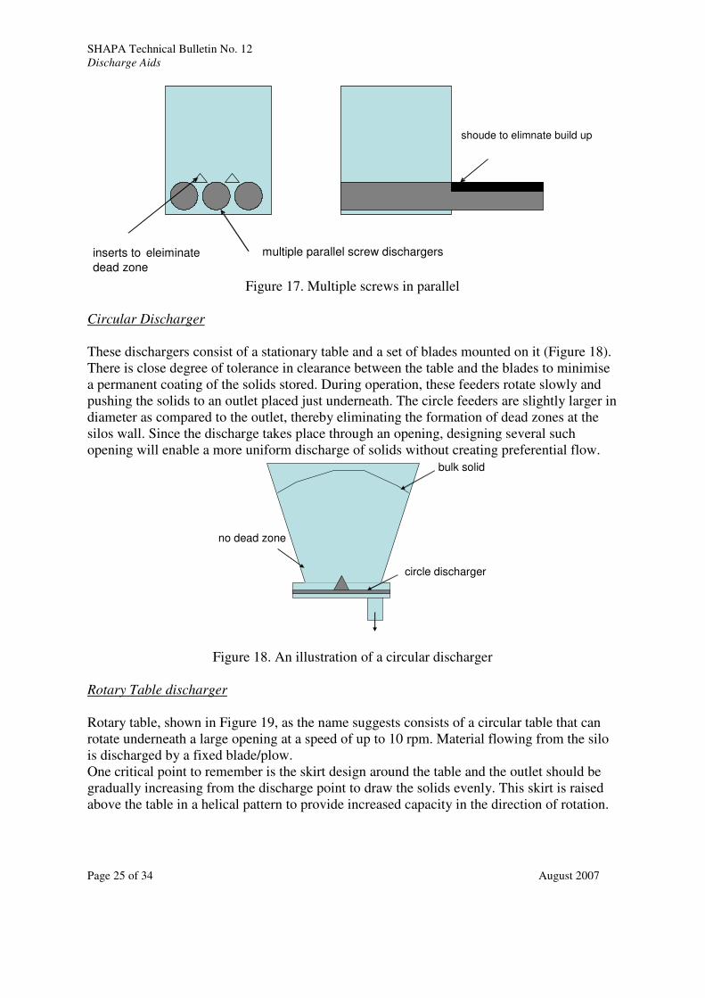
Single or Multiple Screws in Parallel
These are normally considered as part of an integrated design with the bin shape. In the case
illustrated in Figure 17, a set of screw dischargers are used to discharge solids. These
particular units cover almost the entire cross section of the silo, rotating slowly up to 5 rpm.
The conveying part of the design is shrouded to prevent the uncontrolled ‘carry-over’ of
solids.
The design of the flights depends on the solids flow properties and there are several flight
designs and pitch to diameter ratios that govern the extraction pattern of solids. For
progressive discharge, these discharges require gradually increasing pitch to draw the solids
evenly. Ribbon screw flights are used for fine and cohesive solids such as micro talc.
SHAPA Technical Bulletin No. 12
Discharge Aids
Page 25 of 34 August 2007
shoude to elimnate build up
multiple parallel screw dischargersinserts to eleiminate
dead zone
Figure 17. Multiple screws in parallel
Circular Discharger
These dischargers consist of a stationary table and a set of blades mounted on it (Figure 18).
There is close degree of tolerance in clearance between the table and the blades to minimise
a permanent coating of the solids stored. During operation, these feeders rotate slowly and
pushing the solids to an outlet placed just underneath. The circle feeders are slightly larger in
diameter as compared to the outlet, thereby eliminating the formation of dead zones at the
silos wall. Since the discharge takes place through an opening, designing several such
opening will enable a more uniform discharge of solids without creating preferential flow.
circle discharger
bulk solid
no dead zone
Figure 18. An illustration of a circular discharger
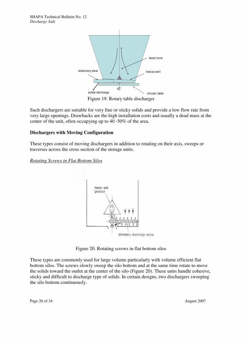
Rotary Table discharger
Rotary table, shown in Figure 19, as the name suggests consists of a circular table that can
rotate underneath a large opening at a speed of up to 10 rpm. Material flowing from the silo
is discharged by a fixed blade/plow.
One critical point to remember is the skirt design around the table and the outlet should be
gradually increasing from the discharge point to draw the solids evenly. This skirt is raised
above the table in a helical pattern to provide increased capacity in the direction of rotation.
SHAPA Technical Bulletin No. 12
Discharge Aids
Page 26 of 34 August 2007
dead zone
circular table
helical skirt
solids discharge
stationary plow
Figure 19. Rotary table discharger
Such dischargers are suitable for very fine or sticky solids and provide a low flow rate from
very large openings. Drawbacks are the high installation costs and usually a dead mass at the
center of the unit, often occupying up to 40 -50% of the area.
Dischargers with Moving Configuration
These types consist of moving dischargers in addition to rotating on their axis, sweeps or
traverses across the cross section of the storage units.
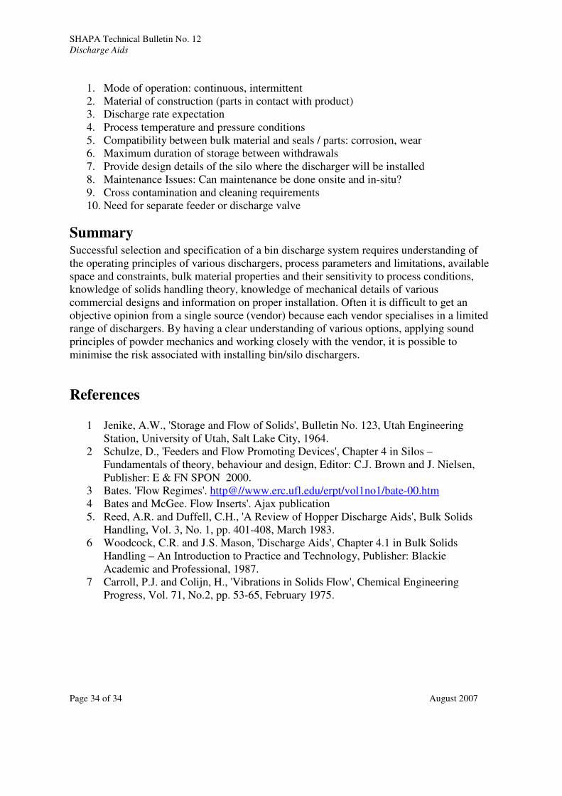
Rotating Screws in Flat Bottom Silos
Figure 20. Rotating screws in flat bottom silos
These types are commonly used for large volume particularly with volume efficient flat
bottom silos. The screws slowly sweep the silo bottom and at the same time rotate to move
the solids toward the outlet at the center of the silo (Figure 20). These units handle cohesive,
sticky and difficult to discharge type of solids. In certain designs, two dischargers sweeping
the silo bottom continuously.

SHAPA Technical Bulletin No. 12
Discharge Aids
Page 27 of 34 August 2007
The drives for screw re-claimers usually have hydraulic motors for better control and start up
torque. The drives can be either housed inside the storage facility, in which case accessibility
is through the outlet. The drives can also be located outside for some of the above types in
which case the outlet design has to accommodate the drives. In case of longitudinal or
rectangular storage facility, drives are placed at one end of the facility while the cables move
back and forth with the discharger
A major drawback of all the units described above is securing access for maintenance and
repair if the discharger breaks down in a pile of bulk solid As this has happened, it is
sensible to pay attention to the design of the latter by calculating the stresses and torques due
to solids, particularly while starting the unit. Additionally, providing blinded ports along the
periphery of silosl enables the discharger to be pulled out for maintenance or any other
reason. Good engineering design is necessary for these designs to be robust and reliable.
Screw-tube Discharger
A recent version of these designs as shown in Figure 21 has a tube and a screw re-claimer is
housed inside of it. The tube rotates independently of the screw and uniformly reclaims the
bulk solids through slots along the length of the tube. The inner screw transports the material
to the end of the tube where it is discharged to a take-away conveyor.
These types consume significantly lower power compared to normal screw dischargers. This
is due to less friction of solids on the tube than the work content of the screw action.
Attrition is also lower in screw-tube types and hence better product integrity is maintained.
Rotating Tube Screw
Conveyor
Direction of Flow Reclaim Openings
Figure 21. An illustration of a screw-tube type discharger
Plow Discharger
The plow dischargers are simple and are easy to maintain. Normally are located under a
conical silo or traveling under a long stockpile. As the plow rotates, it pushes the solids, and
loosens the solid above it and the discharge occurs. In some cases, two plows are used.

SHAPA Technical Bulletin No. 12
Discharge Aids
Page 28 of 34 August 2007
One of the disadvantages of the plow feeder is the dead zone that can extend along the wall
since the penetration of the plow falls short of the silo wall. In order to circumvent this [ 2],
the hopper design at the interface of the plow must include either a straight part or the plow
length has to be longer than the hopper part. In order to overcome the dead zone at the
central part, a cone insert has to be designed properly as shown in Figure 22.
Sliding Frame in Flat Bottom Silos
The sliding frame in a flat bottom silo consists of a frame sliding to and fro on top of it and
promoting solids to fall into a slot across the middle of the floor, on to a screw (Figure 23).
This type of discharger was mainly developed to deal with bulk solids of the most severe
flow characteristics, such as high water content, compressible, highly cohesive materials
(e.g. partially dewatered sewage sludge, paper pulp waste etc.) that cannot be easily be
handled by other means.
Figure 22. Illustration of a plow type discharger

SHAPA Technical Bulletin No. 12
Discharge Aids
Page 29 of 34 August 2007
Figure 23. Illustration of a sliding frame
As opposed to a sliding frame, A variation in the design is the ‘walking floor’ type. This
consists of a flat silo floor frame divided into several strips, which oscillate alternately to and
fro alongside each other. At one end of the assembly there is a clearance down which solids
fall on to a screw conveyor.
Agitators
Hopper Discharger with Arch Breaker
These devices are inside the cone of the silo driven from a universal joint at the outlet. The
length of the arm is almost equal to the slope length of the hopper cone, and rotates slowly,
being free to move and shear the bulk solid. These devices can be retrofitted to an existing
silo without the need to cut the whole bottom off the vessel. Again they can discharge
materials for which gravity-discharge hoppers would be. Impractical.
Figure 24. An illustration of a circular hopper discharger with arch breaker
Ribbons and Conditioning Augers

SHAPA Technical Bulletin No. 12
Discharge Aids
Page 30 of 34 August 2007
Metering or dosing solids that are cohesive, is often undertaken by an augur with a
surrounding ribbon flight for disturbing the solid in the feed hopper
Similar ‘conditioning’, or agitating augurs can also be used in a vertical axis,to assist flow
onto a screw feeder.
Figure 25. An example of conditioning auger
Spiders and Rotating Paddles
In certain cases, spiders and rotating paddle can be fitted in side a hopper. The motion
loosens the solid and hence promotes in discharge.
Flexible walls
Agitation to solids contained in hopper is also imparted by using walls that are totally
flexible or have elastomeric panels on the sides walls. The walls can be inflated or a slow
massaging applied mechanically.to help the solids to flow.
Inflation of the bladders or balloons can be effected by air, forcing the solid to flow. The
sequences of pulsing these inflations must be determined by trials and a procedure has to be
worked out for a given solid or one may consolidate the solid. The operating temperature
may also limit the usage of these types.
Passive Discharge Aids
Gravity flow can also be assisted by using passive devices that change the stresses and flow
patterns within the converging section in a favorable way. BINSERT™, inverted cone
(Chinese Hat) or pyramid and Diamondback™ hoppers are examples of such devices.

SHAPA Technical Bulletin No. 12
Discharge Aids
Page 31 of 34 August 2007
Whilst inserts can offer considerable operating and flow benefits, they are generally the
domain of specialists as it is necessary to consider the following issues:
• Ease of cleaning: passive devices limit access to regions where blocking is most
likely to occur.
• Variability in flow properties: passive devices can be designed to operate within a
limited range of wall friction and cohesive strength.
• Stresses: the loads acting on inserts and its supports can be quite large. Therefore
structural design must be carefully evaluated.
• Impact forces: structural integrity to handle impact forces during filling.
• Fabrication tolerances: define tolerances required for operation.
• Pressure rating of vessel (esp. with flat surfaces such as on Diamondback™
hoppers).
• Effect on secondary operations: Special gas distribution system needs to be designed
to achieve uniform distribution in hopper and purge bins.
Other approaches include use of smooth liners and addition of flow additives to improve
product flowability and/or reduce caking tendency.
Operation of Dischargers – Intermittent vs. Continuous
Bins/hoppers/silo discharger systems can be operated in a number of ways.
1. Operation of discharger required continuously because the critical arching dimension
for instantaneous flow is larger than the outlet.
2. Bin outlet is sufficiently large to provide reliable flow once the flow is initiated. The
outlet size is larger than arching dimension based on instantaneous flow conditions.
Discharger is only required to initiate flow upon stoppage. In such situations, it is
advisable not to overuse a bin discharger.
3. Bin outlet is sized for typical process operating conditions. The discharger is
operated only in case of extended time storage during shut down or unexpected
process upsets.
Selection of Dischargers
STEPS:
a. Determine the maximum operating bounds of variability of the bulk material
and secure the following measured properties: cohesion, time consolidation,
flowability, particle size distribution, fluidisation characteristics, variability in
material, abrasiveness, friability, stickiness, wall friction characteristics,
moisture%, dust explosion potential.

SHAPA Technical Bulletin No. 12
Discharge Aids
Page 32 of 34 August 2007
b. Understand process requirements: installation (existing vs. new silos), height
constraints, feed-out demand, acceptable attrition and abrasion, maintenance
requirements, availability of utilities (compressed air vs. electricity).
c. Short list the class of dischargers that would be suitable for a given
application based on initial set of questions. There might be cases where more
than one method is suitable. See Table 4.
d. Drill down deep into each of the categories to identify suitable dischargers. At
this point, one must consider retrofit situation and new bin/silo design
separately. Retrofit situation imposes many constraints, such as –
1) Ease of installation in existing space
2) Available utilities (electricity, compressed air, inert gas)
3) Access for maintenance
4) Ability to performance maintenance without emptying the product
5) Need for ancillary equipment
6) Effect on process safety and safety during maintenance
7) Need to install discharge aid without shutting down the process
8) Cost
e. Conduct vendor trial, pilot scale test or verify in field.
f. Go back to step c if the concept does not perform satisfactorily during vendor
trials.
Table 4. Preliminary Selection of Discharger Type
Discharger Class Suitable For Unsuitable For
Pneumatic type Powders – cohesive and
fluidisable,
Caked materials, moisture
level is critical, large
particles, floodable,
potential dust explosion
Vibrational type Cohesive, caking, brittle
arching, sticky
powders that tend to
consolidate with vibrations,
spongy, soft,
Mechanical type Very difficult to handle
materials, moisture level is
critical, materials with dust
explosion potential
Silos with high aspect ratio;
friable, springy, soft and
abrasive materials
Passive type Materials that are
marginally unsuitable for
typical hopper design,
locations where utilities (air
/ electricity) are not
available
Materials with high
variability in flow
properties, sticky and
caking type.
Pitfalls with Vendor Trials

SHAPA Technical Bulletin No. 12
Discharge Aids
Page 33 of 34 August 2007
As pointed out earlier, the process of selection of bin dischargers is still very empirical and
dictated by experience of the plant and the vendor with similar material. After making a
preliminary shortlist, the reader is advised to conduct trials at the facility of a reputable
vendor. This is particularly true for proprietary designs. In our experience, a successful trial
often times does not always translate into successful implementation. Here are a few reasons
why -
• The test material was not representative of the actual product being handled. There
are certain limitations imposed by conducting an offline and offsite test.
• The process conditions (temperature, humidity, pressure) are significantly different
that those in the test lab.
• Performance of the bin discharger is sensitive to operating conditions.
• The design does not scale up very well or scale up not well understood.
• The vendor may not be competent or have experience in product class which you are
testing.
• It is difficult to anticipate process upset conditions.
• Mechanical robustness, maintenance and fouling issues are difficult to gauge with a
short term test.
Interfacing Dischargers with Feeders
Dischargers feeding into downstream processes use feeders to regulate the flow rate of
product. It is important to interface the feeders at the outlet of the discharger properly such
that material is uniformly withdrawn across the entire outlet. Preferential withdrawal of
material from one region can lead to dead zones, unexpected stresses, segregation and
potential caking of material. The illustrations in Figure 26 can be extended in principle to
almost all other types of dischargers.
Figure 26. Examples of incorrect interfacing discharger with feeders
Specification of Dischargers
The following line items must be covered while specifying a discharger.
SHAPA Technical Bulletin No. 12
Discharge Aids
Page 34 of 34 August 2007
1. Mode of operation: continuous, intermittent
2. Material of construction (parts in contact with product)
3. Discharge rate expectation
4. Process temperature and pressure conditions
5. Compatibility between bulk material and seals / parts: corrosion, wear
6. Maximum duration of storage between withdrawals
7. Provide design details of the silo where the discharger will be installed
8. Maintenance Issues: Can maintenance be done onsite and in-situ?
9. Cross contamination and cleaning requirements
10. Need for separate feeder or discharge valve
Summary Successful selection and specification of a bin discharge system requires understanding of
the operating principles of various dischargers, process parameters and limitations, available
space and constraints, bulk material properties and their sensitivity to process conditions,
knowledge of solids handling theory, knowledge of mechanical details of various
commercial designs and information on proper installation. Often it is difficult to get an
objective opinion from a single source (vendor) because each vendor specialises in a limited
range of dischargers. By having a clear understanding of various options, applying sound
principles of powder mechanics and working closely with the vendor, it is possible to
minimise the risk associated with installing bin/silo dischargers.
References
1 Jenike, A.W., 'Storage and Flow of Solids', Bulletin No. 123, Utah Engineering
Station, University of Utah, Salt Lake City, 1964.
2 Schulze, D., 'Feeders and Flow Promoting Devices', Chapter 4 in Silos –
Fundamentals of theory, behaviour and design, Editor: C.J. Brown and J. Nielsen,
Publisher: E & FN SPON 2000.
3 Bates. 'Flow Regimes'. http@//www.erc.ufl.edu/erpt/vol1no1/bate-00.htm
4 Bates and McGee. Flow Inserts'. Ajax publication
5. Reed, A.R. and Duffell, C.H., 'A Review of Hopper Discharge Aids', Bulk Solids
Handling, Vol. 3, No. 1, pp. 401-408, March 1983.
6 Woodcock, C.R. and J.S. Mason, 'Discharge Aids', Chapter 4.1 in Bulk Solids
Handling – An Introduction to Practice and Technology, Publisher: Blackie
Academic and Professional, 1987.
7 Carroll, P.J. and Colijn, H., 'Vibrations in Solids Flow', Chemical Engineering
Progress, Vol. 71, No.2, pp. 53-65, February 1975.