shapa technical paper 5 understanding ... - solids handling papers may 2015... · wolfson centre...
TRANSCRIPT

SHAPA TECHNICAL PAPER 5
Understanding and Controlling Attrition and Wear
in Pneumatic Conveying
DR MSA Bradley
Wolfson Centre for Bulk Solids Handling Technology
University of Greenwich
SHAPA Technical Paper No. 5
Understanding and Controlling Attrition and Wear
in Pneumatic Conveying
Dr MSA Bradley
Wolfson Centre for Bulk Solids Handling Technology
University of Greenwich
Introduction
Article developed from a paper first published at a seminar entitled Successful Pneumatic
Conveying organised by the Institution of Mechanical Engineers in Coventry in February
1999
April 2002
SHAPA Technical Paper No. 5
Understanding and Controlling Attrition and Wear
in Pneumatic Conveying
Dr MSA Bradley
Wolfson Centre for Bulk Solids Handling Technology
University of Greenwich
Introduction
Particle attrition, that is to say the breakage of particles in conveying usually leading to the
generation of dust, and pipeline wear, usually at bends, may seem uneasy bedfellows in a
single study. However, they are both caused by the same phenomenon, that is the impact of
particles against the inside walls of the pipe. Consequently, the same measures are effective,
in most cases, at controlling both.
This paper gives a review of the causes of these two problems, the consequences, and the
techniques which may be applied to overcome them in a practical context.
1. THE PROBLEMS
Particle degradation is in most cases undesirable because it can result in
Increased dust content in the product, in turn leading to
problems with dust emission in further handling and
poorer “handleability” of the material, e.g. hang-ups in hoppers, pipeline blockages etc.
Structural damage to the particles, e.g. cracking the shell of grains leading to processing
problems
Increased breadth of particle size distribution, making segregation more severe
Problems with customer perception of the product
Wear in pipelines is equally undesirable because it usually gives rise to
Mess arising from spillage of material through punctures in pipes
Unplanned maintenance in replacing bends and pipeline components
Downtime on process (this is usually the biggest cost by far)
Contamination of transported product with wear particles (usually iron, which causes
“yellowing” of white materials)
2 April 2002

SHAPA Technical Paper No. 5
Understanding and Controlling Attrition and Wear
in Pneumatic Conveying
The occurrence of these problems of wear and particle attrition in pneumatic conveying has
historically been so common that it has put some users off this form of transport, or at least
earned it a bad reputation. In recent years, however, the understanding of the causes of these
effects, and the consequent development of techniques to overcome them, has progressed very
greatly to the point where it is now possible to convey materials which would previously have
caused too many problems.
2. THE MAIN ISSUES
The main mechanism of particle breakage and pipeline wear are one and the same; collisions
between particles and pipe wall, especially at bends. As a particle approaches a bend, so it is
travelling at almost the same velocity as the air, but once it enters the bend it tends to go in a
straight line and collide with the outer wall of the bend, whereas the air is deflected around the
bend. This is purely due to the inertia of the particle, and the particles have to be very small (a
handful of microns) to follow the airflow instead of colliding with the bend wall.
The resulting damage to the particle and the pipe surface are dependent on a number of
factors, as follows.
3. THE ROLE OF VELOCITY
3 April 2002
Puncture point
Fig. 1
A demonstration bend of solid clear acrylic,
worn by the passage of alumina particles
Fig 2
Photograph of a typical pneumatic
conveying line puncture
(viewed from inside the pipe, and from the
direction of flow)
SHAPA Technical Paper No. 5
Understanding and Controlling Attrition and Wear
in Pneumatic Conveying One of the main keys to avoiding the problems in question, is to understand the effect of
particle velocity, which is of course closely related to air velocity.
The energy expended in a collision is a direct function of the velocity beforehand. Consequently,
both particle degradation or fragmentation, and wear of the pipe surface, increases with
increasing particle impact velocity. This relates directly to the deceleration forces experienced by
the particles when impacting against pipeline bends, misalignments etc.
The degree of degradation or wear depends on the mechanical properties, shape and size of
the particles and the mechanical properties and geometry of the pipe wall. However, the
general trend is well documented; for example
Erosion =k.(particle velocity)n
where
k = a constant and
n = a power usually between 2.2 and 2.8 for most materials
is often used to model the rate of wear (Ref. 6), showing that for example a 25% increase in
particle velocity will give rise to something between a 60% and 90% increase in rate of wear.
Particle breakage is less easily quantified, but is usually recognised to follow a similar trend,
i.e. increased velocity leads to disproportionately increased particle damage.
Given this type of relationship, the primary strategy for minimising the degradation and wear
has to be one of reducing particle velocity as far as possible - even small reductions in
velocity will always bring big reductions in these problems.
4. DILUTE AND DENSE PHASE CONVEYING
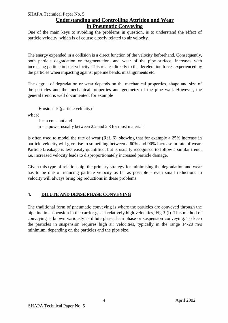
The traditional form of pneumatic conveying is where the particles are conveyed through the
pipeline in suspension in the carrier gas at relatively high velocities, Fig 3 (i). This method of
conveying is known variously as dilute phase, lean phase or suspension conveying. To keep
the particles in suspension requires high air velocities, typically in the range 14-20 m/s
minimum, depending on the particles and the pipe size.
4 April 2002
SHAPA Technical Paper No. 5
Understanding and Controlling Attrition and Wear
in Pneumatic Conveying
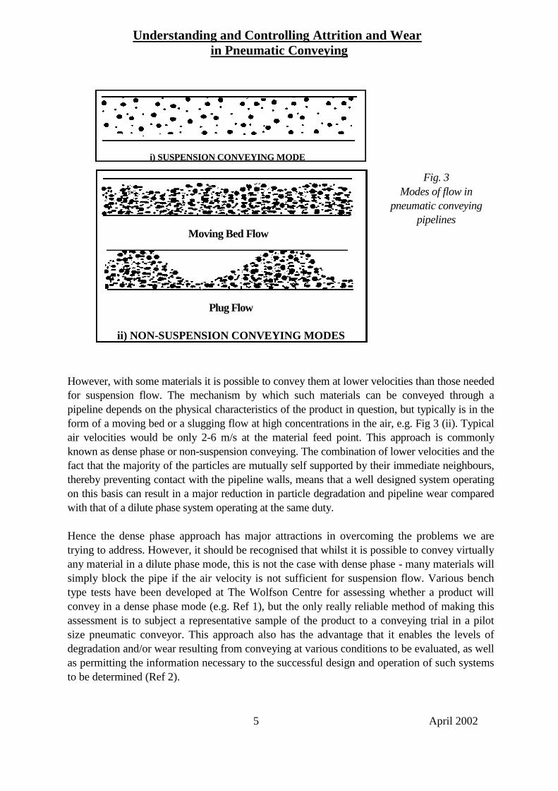
Fig. 3
Modes of flow in
pneumatic conveying
pipelines
However, with some materials it is possible to convey them at lower velocities than those needed
for suspension flow. The mechanism by which such materials can be conveyed through a
pipeline depends on the physical characteristics of the product in question, but typically is in the
form of a moving bed or a slugging flow at high concentrations in the air, e.g. Fig 3 (ii). Typical
air velocities would be only 2-6 m/s at the material feed point. This approach is commonly
known as dense phase or non-suspension conveying. The combination of lower velocities and the
fact that the majority of the particles are mutually self supported by their immediate neighbours,
thereby preventing contact with the pipeline walls, means that a well designed system operating
on this basis can result in a major reduction in particle degradation and pipeline wear compared
with that of a dilute phase system operating at the same duty.
Hence the dense phase approach has major attractions in overcoming the problems we are
trying to address. However, it should be recognised that whilst it is possible to convey virtually
any material in a dilute phase mode, this is not the case with dense phase - many materials will
simply block the pipe if the air velocity is not sufficient for suspension flow. Various bench
type tests have been developed at The Wolfson Centre for assessing whether a product will
convey in a dense phase mode (e.g. Ref 1), but the only really reliable method of making this
assessment is to subject a representative sample of the product to a conveying trial in a pilot
size pneumatic conveyor. This approach also has the advantage that it enables the levels of
degradation and/or wear resulting from conveying at various conditions to be evaluated, as well
as permitting the information necessary to the successful design and operation of such systems
to be determined (Ref 2).
5 April 2002
ii) NON-SUSPENSION CONVEYING MODES
i) SUSPENSION CONVEYING MODE
Moving Bed Flow
Plug Flow

SHAPA Technical Paper No. 5
Understanding and Controlling Attrition and Wear
in Pneumatic Conveying It must be recognised that pipeline bores and associated hardware for systems operating at the
same duty but in dilute or dense phase modes are likely to be quite different. A dense phase
system is likely to be built around a high-pressure blow tank feeder operating on a batch-wise
basis. The pipeline will be smaller than a traditional lean phase system for the same duty, but
the conveying line pressure drop for dense phase transport will be much higher, e.g. 2-6 bar
compared with 0.5-1 bar. Consequently, the significantly higher expansion effects in a dense
phase system means that towards the end of the conveying pipeline the air and particle
velocities may be of the same order as a lean phase system operating at the same duty.
Irrespective of the type of system under consideration it is possible to control air velocities
and therefore particle velocities within reasonable limits by the technique described in the
next section.
An important consideration with dense phase conveying, where particle breakage or pipeline
wear are important, is to avoid the tank at high pressure rapidly venting down the pipeline at the
end of the conveying cycle. At this point the tank has emptied out of solids, but still contains air
at high pressure and as the pipeline itself starts to empty so the reducing volume of material in the
pipeline will be accelerated to high velocities by the pressure of air remaining in the tank. It has
been shown that the very high air velocities present in this phase of the cycle known as
“blowdown” can lead to very high wear and/or high product attrition. Avoiding blowdown means
shutting off the air supply when the tank pressure begins to drop, and possibly beginning the vent
the tank to another location so that there is just enough air left in the tank to complete the cycle of
transport but avoid the high pressure venting along the line. With some materials, notably very
permeable granular materials like plastic pellets or granulated sugar, the air can be shut off and
the tank vented before the tank is empty; the material is left in the pipeline while the tank is
refilled, and conveying will restart when the tank is repressurised. This is a good way of avoiding
blowdown altogether. However, with many materials, this approach will result in a totally
blocked conveying line which cannot be restarted. Some special conveying systems on the
market incorporate air injectors at various points along the pipeline, which enables restarting of a
partially filled line, even with materials which would otherwise cause blockages under such shut-
down conditions, and this is an effective way of avoiding the blowdown problem. Another
approach is to use two blow tanks, either in parallel or in series, to feed the line - when one tank
is empty the other one takes over the feeding duty, or tops up the conveying tank, so that the line
is kept operating continuously thus avoiding blowdown conditions.
5. STEPPED BORE PIPELINES
Increasing the bore of the conveying pipeline at strategic points along its length is an effective
way of controlling the air velocities in the pipeline. As the conveying air flows along the
pipeline its pressure decreases and, as a result, the air velocity increases. This is why it is
almost always the bend at the end of the system which wears out most often! Increasing the
bore of the conveying line at strategic locations along its length allows the air velocities to be
kept down, thereby reducing particle attrition and wear.
6 April 2002
SHAPA Technical Paper No. 5

Understanding and Controlling Attrition and Wear
in Pneumatic Conveying The positioning of the step to the next available pipe size is crucial if the approach is to
operate to maximum effect. If the step in bore is too soon the velocity will be below that for
reliable conveying and a blockage is liable to result; conversely, should the step be too far
down the pipeline the maximum benefit of the approach in terms of reducing particle
velocities and associated attrition and wear will not be fully realised.
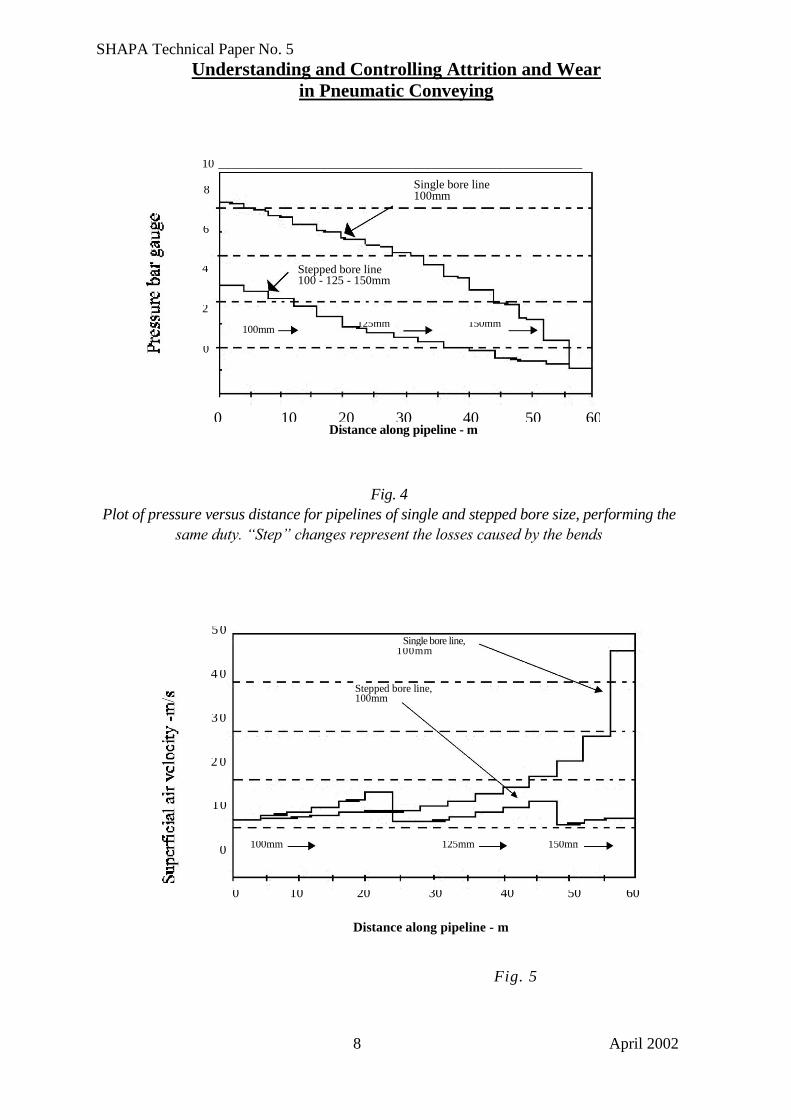
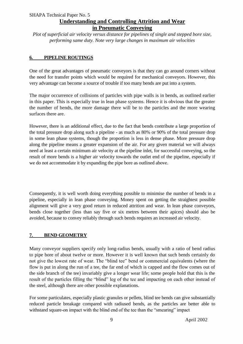
The advantages of this approach vary from application to application, but a design study shown
in Figs 4 and 5 serves well to illustrate the point with regard to wear. This is based on a system
with 15 bends conveying material at 60 tonnes per hour over a pipe run of 60 metres. The design
pickup velocity was 11.8 m/s. In this study, the pipeline was feeding to a metallurgical reactor at
1.3 bar gauge, but the same principle applies if the system is exhausting to atmosphere. With a
pipeline of a single bore size (100mm), the pressure drop was predicted to be 7 bar, and the
outlet air velocity would have been 48 m/s; if the pipe bore was increased to 125 and then
150mm at appropriate points, the pressure drop reduced to 3.5 bar and the maximum air velocity
to 18 m/s. An air velocity of 48 m/s would have caused severe wear of the bends when
conveying the abrasive metal concentrate into the reactor; reducing it to 18 m/s would yield at
least an eight-fold increase in the bend life!
This has most advantage with long distance or dense phase systems, where high pressure
drops lead to high outlet air velocities, but the strong effect velocity has on both particle
attrition and wear means it has merits even for shorter, lower pressure systems. Wherever the
pressure drop in conveying is more than about 0.4 bar, this is an effective technique.
In the past, the major impediment to using stepped bores to maximum effect has been the
difficulty in predicting the pressure profile of the conveying air along the pipeline and
therefore the optimum position of the step to the next bore. However, a method has recently
been developed that enables the benefits of the approach to be maximised (Refs 2, 3).
7 April 2002
SHAPA Technical Paper No. 5
Understanding and Controlling Attrition and Wear
in Pneumatic Conveying
Fig. 4
Plot of pressure versus distance for pipelines of single and stepped bore size, performing the
same duty. “Step” changes represent the losses caused by the bends
Distance along pipeline - m
Fig. 5
8 April 2002
10 ____________________________________________________________
8 Single bore line 100mm
6
4 Stepped bore line 100 - 125 - 150mm
2
125mm 150mm 100mm
0
0 10 20 30 40 50 60 Distance along pipeline - m
4 0
2 0
3 0
5 0
10
0
0 10 20 30 40 50 60
100mm 125mm 150mm
Stepped bore line, 100mm
Single bore line, 100mm
SHAPA Technical Paper No. 5
Understanding and Controlling Attrition and Wear
in Pneumatic Conveying Plot of superficial air velocity versus distance for pipelines of single and stepped bore size,
performing same duty. Note very large changes in maximum air velocities
6. PIPELINE ROUTINGS
One of the great advantages of pneumatic conveyors is that they can go around corners without
the need for transfer points which would be required for mechanical conveyors. However, this
very advantage can become a source of trouble if too many bends are put into a system.
The major occurrence of collisions of particles with pipe walls is in bends, as outlined earlier
in this paper. This is especially true in lean phase systems. Hence it is obvious that the greater
the number of bends, the more damage there will be to the particles and the more wearing
surfaces there are.
However, there is an additional effect, due to the fact that bends contribute a large proportion of
the total pressure drop along such a pipeline - as much as 80% or 90% of the total pressure drop
in some lean phase systems, though the proportion is less in dense phase. More pressure drop
along the pipeline means a greater expansion of the air. For any given material we will always
need at least a certain minimum air velocity at the pipeline inlet, for successful conveying, so the
result of more bends is a higher air velocity towards the outlet end of the pipeline, especially if
we do not accommodate it by expanding the pipe bore as outlined above.
Consequently, it is well worth doing everything possible to minimise the number of bends in a
pipeline, especially in lean phase conveying. Money spent on getting the straightest possible
alignment will give a very good return in reduced attrition and wear. In lean phase conveyors,
bends close together (less than say five or six metres between their apices) should also be
avoided, because to convey reliably through such bends requires an increased air velocity.
7. BEND GEOMETRY
Many conveyor suppliers specify only long-radius bends, usually with a ratio of bend radius
to pipe bore of about twelve or more. However it is well known that such bends certainly do
not give the lowest rate of wear. The “blind tee” bend or commercial equivalents (where the
flow is put in along the run of a tee, the far end of which is capped and the flow comes out of
the side branch of the tee) invariably give a longer wear life; some people hold that this is the
result of the particles filling the “blind” leg of the tee and impacting on each other instead of
the steel, although there are other possible explanations.
For some particulates, especially plastic granules or pellets, blind tee bends can give substantially
reduced particle breakage compared with radiused bends, as the particles are better able to
withstand square-on impact with the blind end of the tee than the “smearing” impact
9 April 2002

SHAPA Technical Paper No. 5
Understanding and Controlling Attrition and Wear
in Pneumatic Conveying with the outside of a long sweep. Recent detailed work at The Wolfson Centre (Ref 4) has
shown this advantage to be very product-specific, for example with rice blind tees gave the
lowest degradation, whereas with sugar and barley radiused bends gave by far the lowest
degradation. In due course it may be that some simple guidance on choice of bend geometry
for minimum degradation will emerge, however in the mean time when faced with a choice of
bend geometry for minimal degradation, it remains important to undertake some short tests on
a rig such as used in this work (Fig. 6).
The drawback of using blind tee bends is that they give rise to substantially higher pressure
drops, in turn leading to greater air expansion along the pipeline, resulting in higher air
velocities and greater wear towards the end of the pipeline. In a system with perhaps just two
or three bends they are worth considering, but where there are more than this, blind tees can
introduce more problems than they solve.
Blind tees should never be used in dense phase conveyors, as the increased pressure drop is
far too great when the material is flowing in “slugs”.
Fig. 6
Schematic of the test rig used for investigation of the effect of bend geometry on particle attrition.
8. BEND MATERIAL
10 April 2002
Receiving Hopper Air Mass Flow Rate Measurement Equipment
Exhauster
Test Bend Load Cell
Pressure Transducer
F e e d H o p p e r

SHAPA Technical Paper No. 5
Understanding and Controlling Attrition and Wear
in Pneumatic Conveying Different materials perform very differently when subject to impact erosion. Extensive studies
of the wear resistance of various materials have been undertaken at many laboratories over the
past decades using a variety of different erosion testing machines, however the machine which
appears to have emerged as offering the best chance of obtaining meaningful results is that
illustrated in fig. 7 below, originally developed by Kleis in Tallinn, Estonia, and improved by
Burnett and Deng at Greenwich.
Fig. 7 (above)
Essential components of the spinning-disc erosion tester used in the studies reported in this
paper. Particles fed into the centre of the spinning disc are accelerated along the radial tubes
and flung out against targets of test material (steel, basalt etc.) ranged in a circle around the
disc
High performance steels
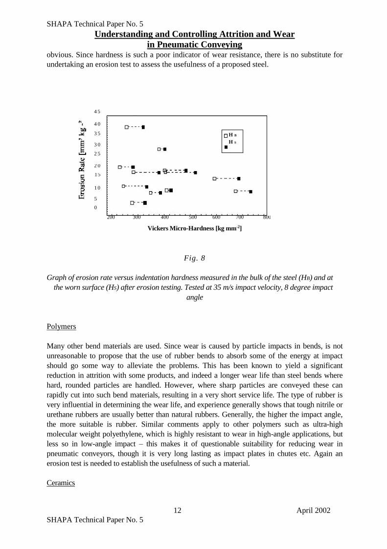
Special steels are probably the most commonly used wear resistant materials. Considerable work
has been done to investigate what mechanical properties determine the erosion resistance of
steels, using the erosion test rig depicted in Fig. 7, and the results have been perhaps surprising;
Fig 8 shows the results of a plot of erosion rate of several steels subject to low-angle impact from
sand particles, versus steel hardness (Ref. 5). The lack of any correlation will be
11 April 2002
SHAPA Technical Paper No. 5
Understanding and Controlling Attrition and Wear
in Pneumatic Conveying obvious. Since hardness is such a poor indicator of wear resistance, there is no substitute for
undertaking an erosion test to assess the usefulness of a proposed steel.
Vickers Micro-Hardness [kg mm-2]
Fig. 8
Graph of erosion rate versus indentation hardness measured in the bulk of the steel (HB) and at
the worn surface (HS) after erosion testing. Tested at 35 m/s impact velocity, 8 degree impact
angle
Polymers
Many other bend materials are used. Since wear is caused by particle impacts in bends, is not
unreasonable to propose that the use of rubber bends to absorb some of the energy at impact
should go some way to alleviate the problems. This has been known to yield a significant
reduction in attrition with some products, and indeed a longer wear life than steel bends where
hard, rounded particles are handled. However, where sharp particles are conveyed these can
rapidly cut into such bend materials, resulting in a very short service life. The type of rubber is
very influential in determining the wear life, and experience generally shows that tough nitrile or
urethane rubbers are usually better than natural rubbers. Generally, the higher the impact angle,
the more suitable is rubber. Similar comments apply to other polymers such as ultra-high
molecular weight polyethylene, which is highly resistant to wear in high-angle applications, but
less so in low-angle impact – this makes it of questionable suitability for reducing wear in
pneumatic conveyors, though it is very long lasting as impact plates in chutes etc. Again an
erosion test is needed to establish the usefulness of such a material.
Ceramics
12 April 2002
SHAPA Technical Paper No. 5
4 5
4 0
3 5
3 0
2 5
H B
H S
2 0
15
1 0
5
0
200 300 400 500 600 700 800
Understanding and Controlling Attrition and Wear
in Pneumatic Conveying The use of hard non-metallic bend materials to resist wear is well established, and this can be
quite effective with some conveyed particles. Ceramics are the largest group and range from
relatively cheap cast basalt rock through more expensive fused aluminas to exotic carbides of
silicon and boron. The problem is that here again, hardness is a very poor indicator of wear
resistance in an erosion situation.
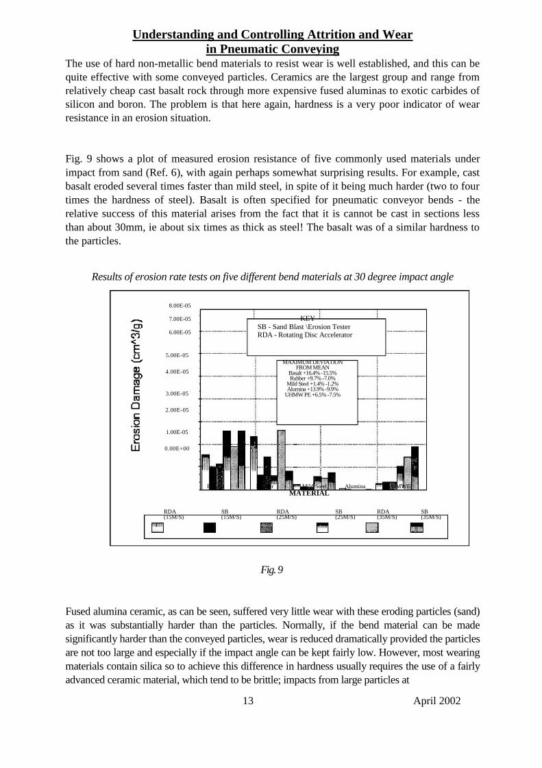
Fig. 9 shows a plot of measured erosion resistance of five commonly used materials under
impact from sand (Ref. 6), with again perhaps somewhat surprising results. For example, cast
basalt eroded several times faster than mild steel, in spite of it being much harder (two to four
times the hardness of steel). Basalt is often specified for pneumatic conveyor bends - the
relative success of this material arises from the fact that it is cannot be cast in sections less
than about 30mm, ie about six times as thick as steel! The basalt was of a similar hardness to
the particles.
Results of erosion rate tests on five different bend materials at 30 degree impact angle
Fused alumina ceramic, as can be seen, suffered very little wear with these eroding particles (sand)
as it was substantially harder than the particles. Normally, if the bend material can be made
significantly harder than the conveyed particles, wear is reduced dramatically provided the particles
are not too large and especially if the impact angle can be kept fairly low. However, most wearing
materials contain silica so to achieve this difference in hardness usually requires the use of a fairly
advanced ceramic material, which tend to be brittle; impacts from large particles at
13 April 2002
Fig. 9
RDA (15M/S)
0.00E+00
8.00E-05
7.00E-05
6.00E-05
4.00E-05
2.00E-05
5.00E-05
3.00E-05
1.00E-05
Bassalt Rubber Mild Steel Alumina UHMWE
MATERIAL
SB (15M/S)
KEY SB - Sand Blast \Erosion Tester RDA - Rotating Disc Accelerator
RDA (25M/S)
MAXIMUM DEVIATION FROM MEAN
Basalt +16.4% -15.5% Rubber +9.7% -7.0%
Mild Steel +1.4% -1.2% Alumina +13.9% -9.9%
UHMW PE +6.5% -7.5%
SB (25M/S)
RDA (35M/S)
SB (35M/S)
SHAPA Technical Paper No. 5
Understanding and Controlling Attrition and Wear
in Pneumatic Conveying high angles tend to break the surface of the ceramic and cause high wear. In many instances
the relatively high cost of such ceramics can be recouped fairly quickly through the avoidance
of downtime and unplanned maintenance; reduced lifetime cost can often result through the
use of these slightly more expensive materials in conjunction with good design.
In the instance shown, both rubber and polyethylene also eroded at high rates compared with
mild steel.
In the absence of general rules for predicting erosion resistance, the best way of choosing a bend
material for minimal operating cost for the time being remains the use of a characterisation test in
a rig such as that shown in Fig. 7.
9. PIPE FITTING
The importance of accurate alignment of pipeline components is often overlooked; yet it is quite
common for severe wear to occur just after joints in a long straight pipe, where particles have hit
the edge presented by misaligned sections and bounced across to the other side of the pipe,
causing wear and eventually puncture. The same misalignment is also likely to increase particle
degradation. To minimise this it is well worthwhile expending some effort on accurate alignment
to avoid such edges against the flow. When using flanged joints, the clearance between flange
and pipe o/d, and clearances in the boltholes, will make it impossible to ensure truly accurate
alignment. In this respect, slip-on strap-clamp type couplings are better as they go straight on to
the outside of the pipe and ensure no misalignment of the pipe ends. Using such couplings will
often give rise to the need for secure pipe support, as they mostly do not give as positive a
location of bends as do flanged joints.
10. SUMMARY OF DESIGN FOR MINIMISING PARTICLE ATTRITION AND
BEND WEAR
The key points to note for either effect are:-
Use the lowest possible air velocity for reliable flow (this is by far the biggest effect)
Convey in dense phase if possible (sadly for many materials this is not possible; there
is no point in trying to “force” a material to convey in dense phase if it won’t do so
reliably)
Use stepped bore pipelines if the pressure drop is more than about 0.4 bar
Minimise the numbers of bends
Choose appropriate geometries of bends if this helps with the product in question
Ensure correct pipe alignment to eliminate edges against the flow
Prevent a blow tank from venting its charge of air along the pipeline as it empties
Choose bend materials for wear resistance if necessary; consider polymers, metals and
ceramics but commission a wear test before making a decision.
14 April 2002
SHAPA Technical Paper No. 5
Understanding and Controlling Attrition and Wear
in Pneumatic Conveying
To amplify the latter point, the effectiveness of the lining material should be tested to ensure it
has a beneficial effect, since the benefit is very dependent on the particles being conveyed.
Alternatively, allow for easy replacement if cheap steel bends are used and regarded as regular
maintenance items.
11. RESEARCH FOR THE FUTURE
Recent efforts in this area have focussed on developing the characterisation side, i.e.
improving the accuracy and understanding of the erosion and particle attrition test rigs which
are in use to produce “erosiveness” figures for bulk solids against bend materials and
“friability” figures for the particles. Currently, attention is turning to the use of these figures
to make more accurate predictions of expected bend life and levels of particle damage in the
plant pipelines.
For wear, Research Council funding was allocated some three years ago to pursue a joint
project between Cambridge and Greenwich Universities and four industrial sponsors, to
develop just such a design and troubleshooting tool for engineers to use. Erosion testing rigs at
the Department of Materials Science at Cambridge and The Wolfson Centre at Greenwich are
being used, together with a full industrial scale pipeline test rig at The Wolfson Centre, to
produce erosion data, explore the mechanics of particle transport, and test predictions; the
Centre for Numerical Modelling at Greenwich is undertaking particle trajectory modelling.
The industrial sponsors bring experience in designing, supplying and using pneumatic
conveying systems, and the facilities to test bend life predictions.
The ultimate goal of the team is to produce a simple spreadsheet model, PC-based, which can
be used by non-specialist engineers to optimise the costs of operating pneumatic conveying
systems in the field. This will have benefits for anyone who uses blowing lines for
transporting hard particles, especially in the minerals, power, port, food and many other
industries.
Currently the project is approaching fruition, and a test protocol and software tool will be
available in the near future. In the mean time, users should take some comfort in the fact that
the current state of knowledge is at least sufficient to enable significant improvements to
plants which have serious wear problems, and allow some forward planning to minimise
problems on new plants.
With regard to particle breakage, work being undertaken through the “QPM” (Quality in
Particulate-Based Manufacturing) project being pursued collaboratively between the
universities of Greenwich and Surrey, and eight industrial partners, has resulted in a version of
the rotating disc erosion tester for measuring the friability of particles in handling; this
15 April 2002
SHAPA Technical Paper No. 5
Understanding and Controlling Attrition and Wear
in Pneumatic Conveying work is being validated at present and the technique will be available shortly. This tester
supersedes the rig shown in fig. 6, and enables the breakage tendency of particles to be
measured much more quickly and cheaply. Predictions of breakage in a plant can then be
made even before the plant is built; this will enable much more effective elimination of such
problems before major costs are incurred..
More information on these developments can be obtained from The Wolfson Centre,
University of Greenwich (www.bulksolids.com).
16 April 2002

SHAPA Technical Paper No. 5
Understanding and Controlling Attrition and Wear
in Pneumatic Conveying
REFERENCES
1 Mainwaring, NJ, 'The Effect of the Physical Properties of Bulk Solid Materials on
Modes of Dense Phase Pneumatic Conveying'., PhD Thesis, Thames Polytechnic, 1988.
2 Bradley, MSA, 'An Improved Method of Predicting Pressure Drop Along Pneumatic
Conveying Pipelines', Proc. 3rd Int. Conf. on Bulk Materials Storage, Handling
and Transportation, Newcastle, Australia, June 1989.
3 Bradley MSA, Pittman, AN, Woodhead SR, ‘Practical Experience with the Design and
Analysis of Pneumatic Conveying Pipelines: Advantages of Employing the Latest
Methods’, Proc 8th Int. Sypm Freight Pipelines, Pittsburgh, USA, Sept 1995
4 The Analysis of Particle Degradation in Pneumatic Conveyors Utilising a Pilot
Sized Test Facility, Accepted for future publication in Proc IMechE Part E
5 O’Flynn DJ, PhD Thesis 1998, University of Greenwich
6 Burnett AJ, PhD Thesis 1996, University of Greenwich
17 April 2002