shop drawing review - mkc associates, inc. csd/09-ed1-045a new...corrections or comments made on a...
TRANSCRIPT

Architecture - Engineering - Planning www.mkcinc.com
Mansfield, Ohio New Philadelphia, Ohio Powell, Ohio 419-525-1102 - phone 330-364-8871 - phone 740-657-3202 - phone 419-525-1428 - fax 330-343-3075 - fax 740-657-1717 - fax
SHOP DRAWING REVIEW
✔
REVIEWEDFURNISH AS CORRECTEDREVISE AND RESUBMITREJECTEDSUBMIT SPECIFIED ITEM
Date:Todd Moore / DLayBy: Feb 6, 2012
Comments:
This review is only for general conformance with (1) the design concept and (2) the informationgiven in the construction documents. Corrections or comments made on a shop drawing duringthis review do not relieve the contractor from compliance with the requirements of the plans andspecifications. Approval of a specific item does not include approval of an assembly of whichthe item is a component. The contractor remains responsible for: dimensions to be confirmed andcorrelated at the job site; information that pertains solely to the fabrication process or to themeans, methods, techniques, sequences and procedures of construction; coordination of theWork with that of all other trades; and performing all Work in a safe and satisfactory manner.
1. The block engine coolant heater shall be 2500 watt, 208 volt single phase. The contractor shall provide 20A-2P breakerinstalled in available space in lieu of 120 volt circuit, new homerun shall be 2#12 & 1#12 GND-3/4”C from same panel. Thespecified 120 volt breaker shall become spare.
2. A remote push button type Emergency stop for the generator shall be located adjacent to the remote annunciator.
3. The maintenance kit shall include all applicable items per specification section 26 32 13, 1.10.
File Name:
263213-1 Generator

Westlake City SchoolsSubmittal Cover Sheet
(To be filled out and submitted with each submittal)
School ___High School___ Contractor: _Turner Logistics Date __1/24/12___
Item:____Generator & ATS___________________
Specification Section: __263213 _ Sub Specification Section: ____263600____________
Contractor’s Submittal # __263213-01__Revision # __0____ Submittal Type ___PDF__________
Lead Time After Approval (wks) _10__ Manufacturer/Supplier: _Kohler/Buckeye Power Sales_
Intended Area of Use, Drawing # and Detail Reference: _____________________________________
Contractor Stamp
APPROVEDBuckeye Power Sales
_____________________________Mark Cronin
_____________________________1-24-12
CM Stamp
TURNER/RESOURCE
Reviewed for general acceptance only. This review does not relieve the Contractor of the responsibility for making the work conform to the requirements of the contract. The Contractor is responsible for all dimensions, correct fabrication and accurate fit with the work of other trades.
SUBJECT TO ARCHITECT’S APPROVAL
Signed: ____________________ Date: _____________
CM Submittal #: ________________________________
Architect Stamp Engineer Stamp
DC 2/3/12
235216-1
263213-1

PROJECT SUBMITTAL
MARK PEPERA OFFICE OF THE TREASURER
BOARD OF EDUCATION OF THE WESTLAKE CITY
SCHOOL DISTRICT
400REOZJ
PROJECT: WESTLAKE HIGH SCHOOL LOCATION: WESTLAKE, OH


B U C K E Y E P O W E R S A L E S C O M P A N Y, I N C .
TABLEOF
CONTENTSBill of Material…………………………………………Pages 3-6 Spec Sheets……………………………………………..Pages 7-58 Generator Data Sheet, pages 8-12 Alternator Data Sheet, pages 13-16 Controller Data Sheet, pages 17-20 Enclosure/Fuel Tank Data Sheet, pages 21-24 Battery Charger Data Sheet, pages 25-28 Line Circuit Breaker Data Sheet, pages 29-42 Remote Annunciator Data Sheet, page 43-46 Transfer Switch Data Sheet, pages 47-58 Emissions Data…………………………………………Pages 59-60 Dimensional Drawings………………………………....Pages 61-68 Generator Drawing, pages 62-64 Enclosure Drawing, page 65 Fuel Tank Drawing, page 66 Transfer Switch Drawing, pages 67-68 Wiring Schematics ……………………………………..Pages 69-76 Controller Schematic, page 70 Controller Wiring Diagram, pages 71-72 Remote Serial Annunciator Diagram, pages 73-74
Transfer Switch Schematic, page 75 Transfer Switch Wiring Diagram, page 76 Miscellaneous…………………………………………..Pages 77-86 Battery Charger Drawing, page 78 Block Heater Drawing, page 79 Line Circuit Breaker Drawings, pages 80-86 Warranty………………………………………………...Pages 87-90 Prototype Test Certifications. ……………………….….Pages 91-94 Prestartup Checklist………..……………………………Pages 95-98

TABLE OF CONTENTSSection Sub-Section LiteratureQuoteModel 400REOZJ Spec SheetsModel KCS-DMTD-0260B Spec SheetsModel KCS-DMTD-0400B Spec SheetsAlternator Data
Alternator Data Sheet 5M4027Emissions Data
Emissions Data Emissions DataEPA Certificate EPA CertificateSCAQMD Permit SCAQMD Permit
Dimensional DrawingsGenerator ADV-7916Accessories ADV-7917Controller ADV-7985Enclosure/Tank Pkg ADV-7990Transfer Switch ADV-7184
Wiring Schematic DiagramsController Schematic Diagram ADV-8000Controller Wiring Diagram GM77987Controller Wiring Diagram GM78246Interconnection Diagram GM78246Remote Serial Annunciator ADV-6990Remote Serial Annunciator GM62554Enclosure Accessories ADV-7035Transfer Switch GM51949Transfer Switch GM51951
MiscBattery Charger ADV-5971Battery Charger Assembly 233968Block Heater GM75809Block Heater GM76113Block Heater GM76113Circuit Breaker ADV-5912Circuit Breaker X-6305Circuit Breaker Mounting ADV-8030
WarrantyWarranty TP-5373Warranty TP-5374Warranty TP-5561Warranty TP-6087
CertificationISO9001 Certificate G15-152Prototype Test Certificate G18-56
Pre-Startup ChecklistPre-Startup Checklist PreStartUpCheckList
2

Job Name: Westlake High SchoolOffer:T110211WH-003800
Version 1.011/2/2011
Page 1
Page 1
DID YOU KNOW BUCKEYE POWER HAS RENTAL GENERATORS To: Mark Pepera
Office of the Treasurer Board of Education of the Westlake City School District 27200 Hilliard Blvd. Westlake, OH 44145
From: Mark CroninPower System SalesBuckeye Power Sales8465 Tower Park DriveTwinsburg, Ohio 44087P: 330-425-9165 F:[email protected]
GENERATOR SET
Model: 400REOZJ
This generator set equipped with a 5M4027 alternator operating at 277/480 volts is rated for 400 kW/500 kVA.Output amperage: 601
ConfigurationQty Description
1 400REOZJ Generator Set, 24V, 60Hz 1 Bracket, LCB Mounting
1 MTG, LCB D-Frame 150A, D to D
1 Panel, J-Box Barrier
1 Panel, J-Box Closure
1 LCB, 150A, DGP, EL, 100%
1 Breaker 1 Right Components
1 Breaker 1 Left Components
1 Breaker Accessories (All Breakers)
1 Nameplate Rating, Standby 130C
1 Decal, UL2200 Listing (Diesel)
1 Voltage,60Hz,277/480V,3Ph,4W,0.8PF
1 Alternator,5M4027, Isolation Mtd,12 Lead
1 Cooling System, Unit Mtd., Radiator, 50C
1 Skid & Mounting, 5M
1 Air Intake, Standard Duty3

Job Name: Westlake High SchoolOffer:T110211WH-003800
Version 1.011/2/2011
Page 2
Page 2
1 Controller, DEC3000, 24V Reconn 1500A
1 Control & Harness, DEC3000
1 Block Heater, 2500W, 190/208V, 1 Ph
1 Run Relay, 24V
1 DEC3000 2Input/5Output Module
1 Flexible Fuel Line
1 Air Cleaner Restriction Ind.
1 Coolant in Genset 17 gals.
1 Battery Charger, Float w/Alarm, 24V-10A
2 Lit Kit, General Maint., 400REOZJ
1 Warranty, 5 Year Comprehensive
1 RSA II, ATS Annunciator
1 Skid Extension, Sound Level 2
1 UL tested Label & Approval w/Genset
1 LCB, 400A, DGP, EL, 100%
1 Shunt Trip, 24VDC, HD/JD/DG Frame
1 Panel, J-Box Closure
1 Panel, J-Box Barrier
1 MTG, LCB D-Frame 400A, D to D
1 Bracket, LCB Mounting
1 Neutral
1 Bus, ABC Lead
1 Power Factor Test,0.8,3Ph Only
1 Certified Test Report
1 Tank Extension, Enclosure
1 Enclosure, Sound L2 Steel
1 774 Gallon (24 Hour) , Double Wall, Subbase Diesel Fuel Tank 5 Gallon Spill Containment Leak Detector Alarm Panel Fuel Level Switches – One (1) Low Level and One (1) High Level Combustible Liquids Label Tank Equipped with accessories to comply with State of Ohio Requirements NOTE: On Site Fuel Tank Pressure Testing As Required By The State of Ohio Fire Marshall To Be Performed By Others NOTE: DIESEL FUEL BY OTHERS
Dimensions – Enclosure & Subbase Tank : 230” L x 70” W x 118” HWeight – Enclosure & Tank (without fuel): 14,834 lbs
4

Job Name: Westlake High SchoolOffer:T110211WH-003800
Version 1.011/2/2011
Page 3
Page 3
AUTOMATIC TRANSFER SWITCH
ATS-1
Model: Model KCS-DMTD-0260B
3 Pole, 4 Wire, Solid Neutral, 0260 Amps, Kohler Standard rated automatic transfer switch, Model KCS-DMTD-0260B, rated 480V, 60 Hz, complete with all standard equipment and housed in a NEMA 4 enclosure.
ConfigurationQty Description
1 KCS-DMTD-0260B 1 Warranty, 5 Year Comprehensive
AUTOMATIC TRANSFER SWITCH
ATS-2
Model: Model KCS-DMTD-0400B
3 Pole, 4 Wire, Solid Neutral, 0400 Amps, Kohler Standard rated automatic transfer switch, Model KCS-DMTD-0400B, rated 480V, 60 Hz, complete with all standard equipment and housed in a NEMA 4 enclosure.
ConfigurationQty Description
1 KCS-DMTD-0400B 1 Warranty, 5 Year Comprehensive
5

Job Name: Westlake High SchoolOffer:T110211WH-003800
Version 1.011/2/2011
Page 4
Page 4
1 Start-up including – antifreeze, lube oil, batteries, preparation (single visit during normal business hours) 1 Warranty – five (5) year comprehensive 1 Load bank test – two (2) hours performed during start-up 1 Annual maintenance agreement 1 Maintenance kit 1 Certified test reports – 0.8 pF 2 Operation and maintenance manual
6

Spec Sheets
7

400REOZJDiesel
Standard Features• Kohler Co. provides one-source responsibility for the
generating system and accessories.• The generator set and its components are prototype-
tested, factory-built ,and production-tested.• The 60 Hz generator set offers a UL 2200 listing.• The generator set accepts rated load in one step.• The 60 Hz generator set meets NFPA 110, Level 1,
when equipped with the necessary accessories andinstalled per NFPA standards.
• A one-year limited warranty covers all systems andcomponents. Two- and five-year extended warrantiesare also available.
• Alternator Features:o The pilot-excited, permanent magnet (PM) alternator
provides superior short-circuit capability.o The brushless, rotating-field alternator has broad
range reconnectability.• Other Features:
o Controllers are available for all applications. Seecontroller features inside.
o The low coolant level shutdown prevents overheating(standard on radiator models only).
o Integral vibration isolation eliminates the need forunder-unit vibration spring isolators.
o An electronic, isochronous governor delivers precisefrequency regulation.
o Multiple circuit breaker configurations.Generator Set Ratings
Standby130CRatings
Alternator Voltage Ph Hz kW/kVA Amps5M4027 277/480 3 60 400/500 601RATINGS: All three-phase units are rated at 0.8 power factor. Standby Ratings: The standby rating is applicable to varying loads for the duration of a power outage. There is no overload capability for this rating.Prime Power Ratings: At varying load, the number of generator set operating hours is unlimited. A 10% overload capacity is available for one hour in twelve. Ratings are in accordance with ISO-8528-1 andISO-3046-1. For limited running time and continuous ratings, consult the factory. Obtain technical information bulletin (TIB-101) for ratings guidelines, complete ratings definitions, and site condition derates. Thegenerator set manufacturer reserves the right to change the design or specifications without notice and without any obligation or liability whatsoever.
400REOZJDiesel
Alternator Voltage Ph Hz kW/kVA Amps5M4027 277/480 3 60 400/500 601
8

Model: 400REOZJ, continued
Alternator Specifications
Specifications AlternatorAlternator manufacturer KohlerType 4-Pole, Rotating-FieldExciter type Brushless, Permanent-Magnet, Pilot ExciterLeads, quantity 12, ReconnectableVoltage regulator Solid State, Volts/HzInsulation NEMA MG1Insulation: Material Class HInsulation: Temperature Rise 130°C, 150°C, StandbyBearing: quantity, type 1, SealedCoupling Flexible discAmortisseur windings FullRotor balancing 125%Voltage regulation, no-load to full-load (with lessthan 0.5% drift due to temp. variation)
Controller Dependent
One-Step Load Acceptance 100% of ratingUnbalanced load capability 100% of Rated Standby Current
• Sustained short-circuit current of up to 300% of the rated current for up to 10 seconds.• Sustained short-circuit current enabling down stream circuit breakers to trip without collapsing the alternator field.• Self-ventilated and dripproof construction.• Vacuum-impregnated windings with fungus-resistant epoxy varnish for dependability and long life.• Superior voltage waveform from a two-thirds pitch stator and skewed rotor.• Brushless alternator with brushless exciter for excellent load response.
Engine
Engine SpecificationsEngine Manufacturer John DeereEngine Model 6135HF485Engine: type 4-Cycle, Turbocharged, Charge Air-CooledCylinder arrangement 6, InlineDisplacement, L (cu. in.) 13.5 (824)Bore and stroke, mm (in.) 132 x 165 (5.2 x 6.5)Compression ratio 16.0:1Piston speed, m/min. (ft./min.) 594 (1950)Main bearings: quantity, type 7, Replaceable InsertRated rpm 1800Max. power at rated rpm, kWm (BHP) 460 (617)Cylinder head material Cast IronCrankshaft material Forged SteelValve (exhaust) material Intake Nickel-Chromium Head, Chromium-Silicone StemGovernor: type, make/model JDEC Electronic L15Frequency regulation, no-load to-full load IsochronousFrequency regulation, steady state ±0.25%Frequency FixedAir cleaner type, all models Dry
Model: 400REOZJ, continued
9

Model: 400REOZJ, continued
Exhaust
Exhaust SystemExhaust Manifold Type DryExhaust flow at rated kW, m³/min. (cfm) 81 (2860)Exhaust temperature at rated kW, dry exhaust, °C(°F)
471 (880)
Maximum allowable back pressure, kPa (in. Hg) Min. 4 (1.2) Max. 10 (3.0)Exh. outlet size at eng. hookup, mm (in.) See ADV Drawing
Engine Electrical
Engine Electrical SystemBattery charging alternator: Ground (negative/positive) Negative Volts (DC) 24 Ampere rating 60Starter motor rated voltage (DC) 24Battery, recommended cold cranking amps (CCA): Qty., CCA rating each Two, 950Battery voltage (DC) 12
Fuel
Fuel SystemFuel type DieselFuel supply line, min. ID, mm (in.) 13 (0.50)Fuel return line, min. ID, mm (in.) 10 (0.38)Max. lift, fuel pump: type, m (ft.) Electronic, 2.1 (6.8)Max. fuel flow, Lph (gph) 196.5 (51.9)Fuel prime pump ElectronicFuel Filter Secondary 2 Microns@ 98% EfficiencyFuel Filter Primary 10 MicronsFuel Filter Water Separator YesRecommended fuel #2 Diesel
Lubrication
Lubrication SystemType Full PressureOil pan capacity, L (qt.) 40.0 (42.3)Oil pan capacity with filter, L (qt.) 42.0 (44.4)Oil filter: quantity, type 1, CartridgeOil cooler Water-Cooled
Model: 400REOZJ, continued
10

Model: 400REOZJ, continued
Cooling
Radiator SystemAmbient temperature, °C (°F) 50 (122)Engine jacket water capacity, L (gal.) 18 (4.8)Radiator system capacity, including engine, L (gal.) 67.2 (17.8)Engine jacket water flow, Lpm (gpm) 469 (124)Heat rejected to cooling water at rated kW, dryexhaust, kW (Btu/min.)
231 (13148)
Heat rejected to air charge cooler at rated kW, dryexhaust, kW (Btu/min.)
122 (6944)
Water pump type CentrifugalFan diameter, including blades, mm (in.) 965 (38)Fan, kWm (HP) 18 (24)Max. restriction of cooling air, intake and dischargeside of radiator, kPA (in. H20)
0.125 (0.5)
* Enclosure with internal silencer reduces ambient temperature capability by 5°C (9°F).
Operation Requirements
Air RequirementsRadiator-cooled cooling air, m³/min. (scfm) * 651 (23000)Combustion air, m³/min. (cfm) 34 (1201)Heat rejected to ambient air: Engine, kW (Btu/min.) 147 (8367)Heat rejected to ambient air: Alternator, kW (Btu/min.)
40 (2277)
*Air density = 1.20 kg/m³ (0.075 lbm/ft³)
Fuel Consumption
Diesel, Lph (gph), at % load RatingStandby Fuel Consumption at 100% load 115.7 Lph (30.6 gph)Standby Fuel Consumption at 75% load 83.8 Lph (22.1 gph)Standby Fuel Consumption at 50% load 57.9 Lph (15.3 gph)Standby Fuel Consumption at 25% load 31.9 Lph (8.4 gph)Prime Fuel Consumption at 100% load 101.3 Lph (26.8 gph)Prime Fuel Consumption at 75% load 75.1 Lph (19.8 gph)Prime Fuel Consumption at 50% load 52.1 Lph (13.8 gph)Prime Fuel Consumption at 25% load 29.6 Lph (7.8 gph)
Model: 400REOZJ, continued
Fuel Consumption
Diesel, Lph (gph), at % load RatingStandby Fuel Consumption at 100% load 115.7 Lph (30.6 gph)
11

Model: 400REOZJ, continued
Dimensions and Weights
Overall Size, L x W x H, mm (in.): 3630 x 1725 x 1993 (142.9 x 67.9 x 78.5)Weight (radiator model), wet, kg (lb.): 3901 (8600)
NOTE: This drawing is provided for reference only and should not be used for planning installation. Contact your local distributorfor more detailed information.
Model: 400REOZJ, continued
NOTE: This drawing is provided for reference only and should not be used for planning installation. Contact your local distributorfor more detailed information.
PLEASE SEE DRAWING ADV7990 FORGENERATOR/ENCLOSURE/FUEL TANKINSTALLATION AND DIMENSIONS.
12

Alternator Data
13

TIB-102 15M4027 60 Hz 4/09k
TIB-102
TECHNICAL INFORMATION BULLETIN
Alternator Data SheetAlternator Model: 5M4027
* Voltage refers to wye (star) connection, unless otherwise specified. Kohler Co. reserves the right to change the design or specificationswithout notice and without any obligation or liability whatsoever.
Alternator Data Sheet5M4027
14

TIB-1022 5M4027 60 Hz 4/09k
TYPICAL DYNAMIC CHARACTERISTICSAlternator Model: 5M4027
Voltage refers to wye (star) connection, unless otherwise specified. Kohler Co. reserves the right to change the design or specificationswithout notice and without any obligation or liability whatsoever.
15

TIB-102 35M4027 60 Hz 4/09k
5M4027, 60 Hz, Low Wye or Delta ConnectionSHORT CIRCUIT DECREMENT CURVE
Full Load Current: 1788 Amps Steady State S.C. Current: 5364 Amps Max. 3 ph. Symm. S.C. Current: 9770 Amps
5M4027, 60 Hz, High Wye ConnectionSHORT CIRCUIT DECREMENT CURVE
Full Load Current: 775 Amps Steady State S.C. Current: 2325 Amps Max. 3 ph. Symm. S.C. Current: 5657 Amps
16

Generator Set Controller
Kohler� Decision-Maker� 3000 Controller
General Description and Function
The Decision-Maker� 3000 generator set controller provides
advanced control, system monitoring, and system diagnostics
for optimum performance.
The Decision-Maker� 3000 controller meets NFPA 110, Level 1
when equipped with the necessary accessories and installed
per NFPA standards.
The Decision-Maker� 3000 controller uses patented software
logic to manage sophisticated functions, such as voltage
regulation and alternator thermal overload protection, normally
requiring additional hardware. Additional features include:
� A digital display and pushbutton/rotary selector dial provide
easy local access to data.
� Measurements selectable in metric or English units.
� Scrolling display shows critical data at a glance.
� Digital display of power metering (kW and kVA).
� Integrated hybrid voltage regulator providing ±0.5%
regulation.
� Built-in alternator thermal overload protection.
Industrial Generator Set Accessories
Decision-Maker� 3000
Volts L1--L2:
480.0 V
G6-100 10/10a Page 1
Generator Set Controller
Kohler Decision-Maker 3000 Controllerr� r�
17

G6-100 10/10a Page 2
FAULT
OFF/RESET AUTO RUN ALARM SILENCE/
LAMP TEST
����� ����
� ��� �
Emergency Stop Switch
Digital Display
Master Control Buttons
Off--Reset/Auto/Run
with Lights
Pushbutton/Rotary
Selector Dial
Alarm Silence/Lamp
Test Button with Light
Annunciator Fault Light
Red--Shutdown,
Yellow--Warning
USB Connection
Alarm Horn (located
inside the controller)
User Interface Controls and Components
� Emergency stop switch
� Backlit LCD digital display with two lines of 12 characters
(see User Interface Displays for menus)
� Alarm horn indicates generator set shutdown and warning faults
� Environmentally sealed membrane keypad with three master control
buttons with lights
� Off/Reset (red)
� Auto (green)
� Run (yellow)
� Pushbutton/rotary selector dial for menu navigation
� Rotate dial to access main menus
� Push dial and rotate to access sub menus
� Press dial for 3 seconds to return to top of main menu
� Annunciator fault light
� System shutdown (red)
� System warning (yellow)
� Alarm silence/lamp test button
� Alarm silence
� Lamp test
� USB connection
� Allows software upgrades
� Provides access for diagnostics
� Dedicated user inputs
� Remote emergency stop switch
� Remote 2-wire start for transfer switch
� Auxiliary shutdown
� Integrated hybrid voltage regulator
� Auto-resettable circuit protection mounted on circuit board
� One relay output standard. Optional five relay output available.
� One analog and three digital inputs standard. Optional two inputs
available.
NFPA 110 Requirements
In order to meet NFPA 110, Level 1 requirements, the generator set
controller monitors the engine/generator functions and faults shown
below.
� Engine functions:
� Overcrank
� Low coolant temperature warning
� High coolant temperature warning
� High coolant temperature shutdown
� Low oil pressure shutdown
� Low oil pressure warning
� High engine speed
� Low fuel (level or pressure) *
� Low coolant level
� EPS supplying load
� High battery voltage
� Low battery voltage
� General functions:
� Master switch not in auto
� Battery charger fault *
� Lamp test
� Contacts for local and remote common alarm
� Audible alarm silence button
� Remote emergency stop *
* Functions require optional input sensors or kits
User Interface Displays
The listing below has � denoting main menus and � denoting sub-menus.
� Overview
� Software version
� Active shutdowns and warnings (if any are present)
� Engine run time, total hours
� Average voltage line-to-line
� Frequency
� Average current
� Coolant temperature
� Fuel level or pressure *
� Oil pressure
� Battery voltage
� Engine Metering
� Engine speed
� Oil pressure
� Coolant temperature
� Battery voltage
� Generator Metering
� Total power, VA
� Total power, W
� Rated power, %
� Voltage, L--L and L--N for all phases
� Current, L1, L2, L3
� Frequency
� GenSet Information
� Generator set model number
� Generator set serial number
� Controller serial number
� GenSet Run Time
� Engine run time, total hours
� Engine loaded, hours
� Number of engine starts
� Total energy, kWh
� GenSet System
� System voltage
� System frequency, 50 or 60 Hz
� System phase, single or three (wye or delta)
� Power rating, kW
� Amp rating
� Power type, standby or prime
� Measurement units, metric or English (user selectable)
� Alarm silence, always or auto only (NFPA 110)
� GenSet Calibration
� Voltage, L--L and L--N for all phases
� Current, L1, L2, L3
� Reset calibration
� Voltage Regulation
� Adjust voltage, ±10%
� Digital Inputs
� Input settings and status
� Digital Outputs
� Output settings and status
� Analog Inputs
� Input settings and status
� Event Log
� Event history (stores up to 1000 system events)
* Function requires optional input sensors or kits
18

G6-100 10/10a Page 3
Controller Features
� AC Output Voltage Regulator Adjustment. The voltage
adjustment provides a maximum of ±10% of the system voltage.
� Alarm Silence. The controller can be set up to silence the alarm
horn only when in the AUTO mode for NFPA-110 application or
Always for user convenience.
� Alternator Protection. The controller provides generator set
overload and short circuit protection matched to each alternator for
the particular voltage/phase configuration.
� Automatic Restart. The controller automatic restart feature
initiates the start routine and recrank after a failed start attempt.
� Common Failure Relay. This relay is integrated on the controller
circuit board. Contacts are rated 2 amps at 32 VDC or 0.5 amp at
120 VAC.
� Cyclic Cranking. The controller has programmable cyclic cranking.
� ECM Diagnostics. The controller displays engine ECM fault code
descriptions to help in engine troubleshooting.
� Engine Start Aid. The starting aid feature provides control for an
optional engine starting aid.
� Event Logging. The controller keeps a record (up to 1000 entries)
for warning and shutdown faults. This fault information becomes a
stored record of system events and can be reset.
� Historical Data Logging. Total number of generator set successful
starts is recorded and displayed.
� Integrated Hybrid Voltage Regulator. The voltage regulator
provides ±0.5% no-load to full-load regulation with three-phase
sensing.
� Lamp Test. Press the alarm silence/lamp test button to verify
functionality of the indicator lights.
� Measurement Units. The controller provides selection of English
or metric displays.
� Power Metering. Controller digital display provides kW and kVA.
� Programming Access (USB). Provides software upgrades and
diagnostics.
� Remote Reset. The remote reset function resets faults and allows
restarting of the generator set without going to the master control
switch off/reset position.
� RSA II Remote Monitoring Panel. The controller is compatible
with the Kohler� Remote Serial Annunciator (RSA II).
� Run Time Hourmeter. The generator set run time is displayed.
� Time Delay Engine Cooldown (TDEC). The TDEC provides a time
delay before the generator set shuts down.
� Time Delay Engine Start (TDES). The TDES provides a time delay
before the generator set starts.
Controller Functions
The following chart shows which functions cause a warning or shutdown.
All functions are available as relay outputs.
Warning causes the fault light to show yellow and sounds the alarm horn
signaling an impending problem.
Shutdown causes the fault light to show red, sounds the alarm horn, and
stops the generator set.
Warning
Function
Shutdown
Function
Engine Functions
Critically high fuel level * �
ECM communication loss �
ECM diagnostics � �
Engine over speed ��
Engine start aid active
Engine under speed �
Fuel tank leak * � �
High battery voltage �
High coolant temperature � ��
High fuel level * �
Low battery voltage �
Low coolant level �
Low coolant temperature �
Low cranking voltage �
Low engine oil level * � �
Low fuel level (diesel models) * � �
Low fuel pressure (gas models) * �
Low oil pressure � ��
No coolant temperature signal �
No oil pressure signal �
Overcrank ��
Speed sensor fault �
General Functions
Alarm horn silenced
Analog inputs � �
Battery charger fault * �
Chicago code active *
Common fault (includes �) �
Common warning �
Digital inputs � �
Emergency stop ��
Engine cooldown (delay) active
Engine start delay active
Engine started
Engine stopped
EPS supplying load
Generator running
Input/output communication loss �
Internal failure �
Master switch not in auto �
NFPA 110 alarm active
Remote start
System ready
Generator Functions
AC sensing loss � �
Alternator protection �
Ground fault input * �
kW overload �
Locked rotor �
Overfrequency �
Overvoltage (each phase) �
Underfrequency �
Undervoltage (each phase) �
� Standard functions
� Available user functions
* Functions require optional input sensors or kits
� Items included with common fault shutdown
19

© 2009, 2010 by Kohler Co., All rights reserved.
DISTRIBUTED BY:
G6-100 10/10a Page 4
Controller Specifications
Decision-Maker� 3000—Software Version 1.00 or higher
� Power source with circuit protection: 12- or 24-volt DC
� Power drain: 200 milliamps
� Humidity range: 5% to 95% noncondensing
� Operating temperature range: --40°C to +70°C (--40°F to +158°F)
� Storage temperature range: --40°C to +85°C (--40°F to +185°F)
� Standards:
� CE Directive
� NFPA 99
� NFPA 110, Level 1
� UL 508
� ASTM B117 (salt spray test)
� Panel dimensions—W x H, 229 x 160 mm (9.0 x 6.3 in.)
Decision-Maker� 3000 Available Options
� Float/Equalize Battery Charger available with 6 or 10 amp DC volt
output. The 10 amp models are available with and without NFPA
alarm to signal a battery charger fault.
� Prime Power Switch prevents battery drain during generator set
non-operation periods and when the generator set battery cannot
be maintained by an AC battery charger.
� Remote Emergency Stop Switch available as a wall mounted
panel to remotely shut down the generator set.
� Remote Monitoring Panel. The Kohler� Remote Serial
Annunciator (RSA II) enables the operator to monitor the status of
the generator set from a remote location, which may be required for
NFPA 99 and NFPA 110 installations.
� Run Relay provides a relay indicating that the generator set is
running.
� Shunt Trip Wiring provides relay outputs to trip a shunt trip circuit
breaker and to signal the common fault shutdowns. Contacts rated
at 10 amps at 28 VDC or 120VAC.
� Two Input/Five Output Module provides a generator set mounted
panel with two inputs and five relay outputs.
Kohler Power Systems
Asia Pacific Headquarters
7 Jurong Pier Road
Singapore 619159
Phone (65) 6264-6422, Fax (65) 6264-6455
KOHLER CO., Kohler, Wisconsin 53044 USA
Phone 920-457-4441, Fax 920-459-1646
For the nearest sales and service outlet in the
US and Canada, phone 1-800-544-2444
KohlerPower.com
Availability is subject to change without notice. Kohler Co. reserves the
right to change the design or specifications without notice and without
any obligation or liability whatsoever. Contact your local Kohler�
generator set distributor for availability.
20

Industrial Generator Set AccessoriesSound Enclosure
with Fuel TankPackage
Sound Enclosure Standard Features• Internal silencer, flexible exhaust connector and rain
cap.• Mounts to generator set skid. Steel construction with
hinged and removable doors.• Fade-, scratch-, and corrosion-resistant Kohler®
cream beige polyurethane enamel.• Lockable, flush-mounted door latches.• Air inlet louvers reduce rain entry.• Internal vertical discharge plenum directs air up to
reduce noise.• Accoustic insulation that meets UL 94 HF1
flammability classification.• Sound enclosure offering level 2 sound reduction
using acoustic insulation. See specification at theback of this document for sound pressure dB(A) at 7m (23 ft.)
Subbase Fuel Tank Features• The above-ground rectangular secondary
containment tank mounts directly to the generator set,below the generator set skid (subbase).
• Both the inner and outer tanks have emergency reliefvents.
• Flexible fuel lines are provided with subbase fuel tankselection. Stainless steel fuel lines are an availableoption.
• The secondary containment tank´s constructionprotects against fuel leaks or ruptures. The inner(primary) tank is sealed inside the outer (secondary)tank. The outer tank contains the fuel if the inner tankleaks or ruptures.
• State tanks with varying capacities are an availableoption.
Sound Enclosurewith Fuel Tank
Package
Sound Enclosure Standard Features
Subbase Fuel Tank Features
21

Sound Enclosure with Fuel Tank Package, continued
Sound Enclosure Features• Heavy-duty formed panels, solid construction. Preassembled package offering corrosion resistant, dent resilient structure
mounting directly to the generator set skid.• Polyurethane enamel paint. Superior finish, durability, and appearance.• Internal exhaust silencer offering maximum component life and operator safety.• Service access. Multi-personnel doors for easy access to generator set control and servicing of the fuel fill, fuel gauge, oil
fill, and battery.• Interchangeable modular panel construction. Allows complete serviceability or replacement without compromising
enclosure design.• Bolted panels facilitate service, future modification upgrades, or field replacement.• Cooling/combustion air intake. Weather protective designs using fixed air inlet louvers. Sized for maximum cooling airflow.• Cooling air discharge. Attenuated models offering an internal vertical discharge scoop that redirects cooling air up and above
the enclosure to reduce noise.• Attenuated design using dual silencers connected in series and acoustic insulation UL 94 HF1 listed for flame resistance.
Sound Enclosure with Fuel Tank Package, continued
22

Sound Enclosure with Fuel Tank Package, continued
Subbase Fuel Tank• Extended operation. Optional tank capacities of multiple hour requirements.• UL listed. Secondary containment generator set base tank meeting UL 142 tank requirements.• NFPA compliant. Designed to comply with the installation standards of NFPA 30 and NFPA 37.• Integral external lift lugs. Enables crane with spreader-bar lifting of the complete package (empty tank, mounted generator
set, and enclosure) to ensure safety.• Emergency pressure relief vents. Vents ensure adequate venting of inner and outer tank under extreme pressure and/or
emergency conditions.• Normal vent with cap. Vent is raised above lockable fuel fill.• Fuel level sender with fuel level and low and high fuel warning annunciated through the generator set controller.• Leak detection switch. Annunciates a contained primary tank fuel leak condition at generator set control.• Electrical stub-up area.Fuel TankCapacity,L (gal.)
Est.Fuel
SupplyHours at
60 Hzwith Full
Load
Max.Length,mm (in.)
Max.Width,
mm(in.)
Enclosureand Fuel
TankLength,mm (in.)
Enclosureand Fuel
TankWidth, mm
(in.)
Enclosureand Fuel
TankWeight, kg
(lb.)
Enclosureand Fuel
TankHeight, mm
(in.)
FuelTank
Height(H), mm
(in.)
SoundPressure
at 7m(23ft.),dB(A)
Max.Height,
mm(in.)
Weight,kg (lb.)
2930 (774) 24 5830(230)
1779(70)
6729(14834)
3007 (118) 584(23)
73
Sound Enclosure with Fuel Tank Package, continued
Fuel TankCapacity,L (gal.)
(774)
Est.Fuel
SupplyHours at
60 Hzwith Full
Load24
Max.Length,mm (in.)
(230)
Max.Width,
mm(in.)
(70)
Enclosureand Fuel
TankWeight, kg
(lb.)
(14834)
Enclosureand Fuel
TankHeight, mm
(in.)
(118)
FuelTank
Height(H), mm
(in.)
(23)
SoundPressure
at 7m(23ft.),dB(A)
73
23

Sound Enclosure with Fuel Tank Package, continued
AccessoriesEnclosure Silencer OptionInternal Silencer, sound enclosure, level 2
Miscellaneous Enclosure AccessoriesSkid Extensions. Steel construction (for aluminum or steelenclosures)
Sound Enclosure with Fuel Tank Package, continued
24

Industrial Generator Set AccessoriesFloat/Equalize
Battery Charger
Standard Features• Kohler automatic battery chargers feature two
charging modes to keep lead-acid and nickel-cadmium batteries fully charged without overcharging.The battery charger automatic float-to-equalizeoperation maintains battery voltage with no manualintervention.
• Temperature compensation feature preventsovercharging or undercharging battery at high/lowambient temperatures.
• Current-limiting circuitry prevents battery charger fromoverload at low battery voltage and during a shortcircuit. The ten amp DC current limit allows the batterycharger to remain connected to the battery duringengine cranking.
• Battery charger complies with NFPA 110 coderequirements when equipped with optional alarmcircuit board. Alarm board features low batteryvoltage, high battery voltage, and battery chargermalfunction alarm contacts.
SpecificationsInstalled Battery NFPA 110 Alarm Outputs Output Number of Cells
Voltage Amps Lead Acid Ni-CdGM78809-KA1 Yes 24 10 12 18
Battery Charger Kit GM78809-KP1Input Voltage 120/240 VACInput Frequency 120/240VAC, 50/60 HzDC Voltage Regulation ±1%Dimensions (L x W x D) 271 x 143 x 422 mm (10.67 x 5.63 x 16.63 in.)Weight 11.8 kg (26 lb.)
Float/EqualizeBattery Charger
OutputVoltage Amps
24 10
25

Float/Equalize Battery Charger, continued
Automatic Float to Equalize
When the battery loses its charge, the battery chargeroperates in the High Rate Constant Current Mode until thebattery voltage rises to the preset equalize level.At thepreset equalize level, the battery charger switches to theconstant voltage Equalize Mode until the current requiredto maintain this voltage drops to 50% of the batterycharger's high rate current.The battery charger thenswitches to the lower constant voltage Float Mode whenthe battery nears full charge. The battery chargercontinues to operate in this mode until AC input powerdisconnects or the current required to maintain the batteryat the float voltage setting exceeds 6 amps.
Temperature Compensation
The battery charger compensates for battery temperatureusing a negative temperature coefficient. The batterycharger provides temperature compensation of -2mv/°Cper cell over the ambient temperature range of -40°C upto 60°C. The temperature compensation automaticallyadjusts the float and equalize voltage settings to preventthe battery from overcharging at high ambienttemperatures and undercharging at low ambienttemperatures.
Float/Equalize Battery Charger, continued
26

Float/Equalize Battery Charger, continued
Standard Features
• Ammeter and voltmeter indicate battery charging rate with 5% full-scale accuracy. POWER ON lamp indicates batterycharger is operating.
• AC input and DC output fuses prevent battery charger damage from abnormal overload and short-circuit conditions.
• Operational temperature range is from 40°C (--40°F) to 60°C (140°F). Battery charger float equalize voltageautomatically adjust throughout the temperature range.
• Reverse polarity protection circuitry prevents battery charger from energizing if improperly connected.
• Internal terminal blocks for AC input and DC output/ sensing lead connections.
• DC voltage regulation of ±1% from no load to full load and AC input line voltage variations of ±10%.
• UL listed/CSA certified.
• Wall-mount, slotted enclosure with knockouts for customer conduit installation. Reconnection blocks allowoperation at 120 or 240 volts AC, single phase, 50 or 60 hertz.
• Battery charger circuitry protected from AC line and DC load voltage spikes and transients.
• Terminal block for remote battery sensing leads.
• Automatic float-to-equalize operation with individual potentiometer adjustments. Charge up to 12 lead-acid or 18nickel-cadmium battery cells.
• No adjustments are necessary for lead-acid or nickel-cadmium batteries.
• Oversized transformer and SCR heatsink allow constant current charging at 10 amps up to the equalize voltagesetting for fastest battery charging.
Note: The battery charger will discharge the engine starting battery(ies) when the battery charger is connected to thebattery(ies) and is not connected to an AC power supply. To prevent engine starting battery(ies) discharge, install batterycharger relay kit GM39659.
Float/Equalize Battery Charger, continued
27

Float/Equalize Battery Charger, continuedFloat/Equalize Battery Charger, continued
28

PowerPact® D-Frame Circuit Breakers and SwitchesGeneral Information
708/2009© 2007–2009 Schneider Electric
All Rights Reserved
Section 1—General Information
Introduction
PowerPact® D-frame electronic trip molded case circuit breakers are designed to protect electrical systems from damage caused by overloads and short circuits. All circuit breakers are designed to open and close a circuit by nonautomatic means and to open the circuit automatically on a predetermined overcurrent. The D-frame circuit breakers use an electronic trip system to signal the circuit breaker to open automatically.
For information on other PowerPact molded case circuit breakers manufactured by Square D®, see the Class 611, 612 and 613 catalogs.
Features and Benefits
D-frame electronic trip circuit breakers:
• Provide overload and short-circuit protection• Are true RMS sensing devices• Provide means to manually disconnect power to the circuit • Provide enhanced coordination by their adjustability• Provide high interrupting ratings and withstand ratings• Use many of the same accessories as other PowerPact circuit breakers• Have a wide range of NEMA and IEC operating mechanisms
Table 1: D-Frame Circuit Breakers and Switches
Circuit Breaker Switches Motor Circuit Protectors
Rated Current (A) 150–600 A 400 A, 600 A 400–600 A
Application
pushto
trip
pushto
trip
29

© 2007–2009 Schneider ElectricAll Rights Reserved
PowerPact® D-Frame Circuit Breakers and Switches General Information
808/2009
Table 2: Catalog Numbering
Interrupting Rating
UL/CSA/NOM IEC 60947-2 Icu/Ics
240 Vac 480 Vac 600 Vac 220/240 Vac 380/440/415 Vac 500/525 Vac 250 Vdc 500 Vdc
G 65 kA 35 kA 18 kA 65/65 kA 35/35 kA 18/18 kA 20 kA 20 kA
J 100 kA 65 kA 25 kA 100/100 kA 65/65 kA 25/25 kA 20 kA 20 kA
L 125 kA 100 kA 25 kA 125/125 kA 100/100 kA 50/50 kA 20 kA 20 kA
1 4P circuit breaker available in plug-in, draw-out and rear-connected only. Availability of 4P bus-connected and lug configurations to be announced.
Trip Unit
E20 STR23SP (LS)E53 STR53UP-F (LSI)E54 STR53UP-FT (LSIG)E58 STR53UP-FI (LSI)E59 STR53UP-FTI (LSIG)F40 150, 250, or 400 A Frame Only (No trip unit)F60 600 A Frame Only (No trip unit)M36 400 A Motor Circuit Protector (MCP)M42 600 A Motor Circuit Protector (MCP)S40 400 A Molded Case SwitchS60 600 A Molded Case Switch
Poles
3 3P4 4P1
5 4P+Oversized Neutral1
I-Line® Phasing(Future Offering)
Frame
Amperage
150 60–150 A250 100–250 A400 160–400 A600 240–600 A000 Switch
Voltage
6 600 Vac7 500 Vdc
(Future)
Terminations
L Lugs Line/Load SideM Lugs ON Side, Bus OFF SideP Lugs OFF Side, Bus ON SideF Bus Bar Both SidesS Rear ConnectedN Plug-InD Drawout
Interruption Rating (kA)
Accessory Suffix Code (See Table 3 and Section 6)
D L L 3 6 250 T – – – – –
Brand
blank Square DN Schneider Electric
Table 3: Accessory Suffix Codes (Building Sequence as Listed)
(1) Auxiliary Switch (3) Shunt TripVoltage
(4) Undervoltage Release UVR (5) Motor Operator
Suffix Contacts Kit No. Suffix Kit No. Suffix Kit No. Suffix Voltage Kit No.AA 1A/1B Standard S29450 SK S29384 24 Vac UK S29404 ML 48/60 Vac S32839AB 2A/2B Standard 2x S29450 SL S29385 48 Vac UL S29405 MA 120 Vac S32840AE 1A/1B Low Level S29482 SA S29386 120 Vac UA S29406 MD 277 Vac S32841AF 2A/2B Low Level 2x S29482 SD S29387 208–277 Vac UD S29407 MF 380/415 Vac S32845
(2) Alarm/Overcurrent Trip SwitchSH S29388 380–480 Vac UH S29408 MH 440/480 Vac S32847SJ S29389 525–600 Vac UJ S29409 MO 24/30 Vdc S32843
Suffix Switch Kit No. SN S29382 12 Vdc UN S29402 MP 48/60 Vdc S32844BC Alarm Switch (SD) S29450 SO S29390 24 Vdc UO S29410 MR 110/130 Vdc S32845
BH Alarm Switch (SD) Low-Level S29452 SU S29391 30 Vdc UU S29411
MS 250 Vdc S32846
(6) IEC Style Rotary HandleBD SDE Standard S29450 SP S29392 48 Vdc UP S29412BJ SDE Low-Level S29452 SV S29383 60 Vdc UV S29403 Suffix Handle Type (color) Kit No.
BE SD and SDE Standard 2 S29450 SR S29393 125 Vdc UR S29413
RD12 Direct Mount (black) 32597RE12 Extended Door Mount (black) 32598
BK SD and SDE Low-Level 2 S29452 SS S29394 250 Vdc US S29414
RT12 Telescoping (black) 32603RD22 Direct Mount (red) 32599RE22 Extended Door Mount (red) 32600— MCC Conversion Accessory 32606
30

PowerPact® D-Frame Circuit Breakers and SwitchesGeneral Information
908/2009© 2007–2009 Schneider Electric
All Rights Reserved
Features
PowerPact electronic trip circuit breakers have a molded case made of a glass-reinforced insulating material (thermal set composite resin) that provides high dielectric strength. These circuit breakers:
• Are available in either dual-rated UL/IEC or IEC-only constructions• Dual-rated UL/IEC circuit breakers are also CSA and ANCE certified• Are manufactured in unit-mount, plug-in and drawout constructions• Share common tripping of all poles• Can be mounted and operated in any position• Are available in motor circuit protector and automatic molded case switch constructions• Can be reverse connected, without restrictive LINE and LOAD markings• Meet the requirements of NEC® Sections 240-6 by providing a means to seal the rating plug and
trip unit adjustments• Have field-interchangeable trip units
Circuit Breaker Ratings
Interrupting Rating
The interrupting rating is the highest current at rated voltage which the circuit breaker is designed to safely interrupt under standard test conditions. Circuit breakers must be selected with interrupting ratings equal to or greater than the available short-circuit current at the point where the circuit breaker is applied to the system (unless it is a branch device in a series-rated combination). Interrupting ratings are shown on the front of the circuit breaker.
Ampere Rating (Continuous Current Rating)
The ampere rating (or continuous current rating) (Ir) is the maximum current that a circuit breaker can carry. The sensor size (In) is the maximum ampere rating for a specific circuit breaker and is based on the size of the sensor inside the circuit breaker (sensors are an integral part of the D-frame circuit breaker and cannot be removed or replaced). This value is printed in a window above the trip unit.
NOTE: The maximum ampere rating a circuit breaker family can carry is called the frame size. Sensor size is less than or equal to frame size.
The ampere rating of an electronic trip circuit breaker is determined by the mathematical equation:
Ampere Rating = Sensor Size (Io) x Long-Time (Ir)
The rating plug varies the circuit breaker ampere rating as a function of its sensor size. Rating plugs have nine dial settings; the multiplier values corresponding with each setting are printed on the rating plug. The maximum setting range is 0.4–1.0 x In.
Table 4: UL/IEC Circuit Breaker Interrupting Ratings (See Table 18 and Table 22 for additional ratings.)
Circuit Breaker
UL/CSA Rating (60 Hz)IEC 60947-2 Rating (50/60 Hz)
240 Vac 380/415 Vac
240 Vac 480 Vac 600 Vac Icu Ics Icu IcsDG 65 kA 35 kA 18 kA 85 kA 85 kA 45 kA 45 kADJ 100 kA 65 kA 25 kA 100 kA 100 kA 70 kA 70 kADL 150 kA 100 kA 25 kA 150 kA 150 kA 150 kA 150 kA
31
© 2007–2009 Schneider ElectricAll Rights Reserved
PowerPact® D-Frame Circuit Breakers and Switches General Information
1408/2009
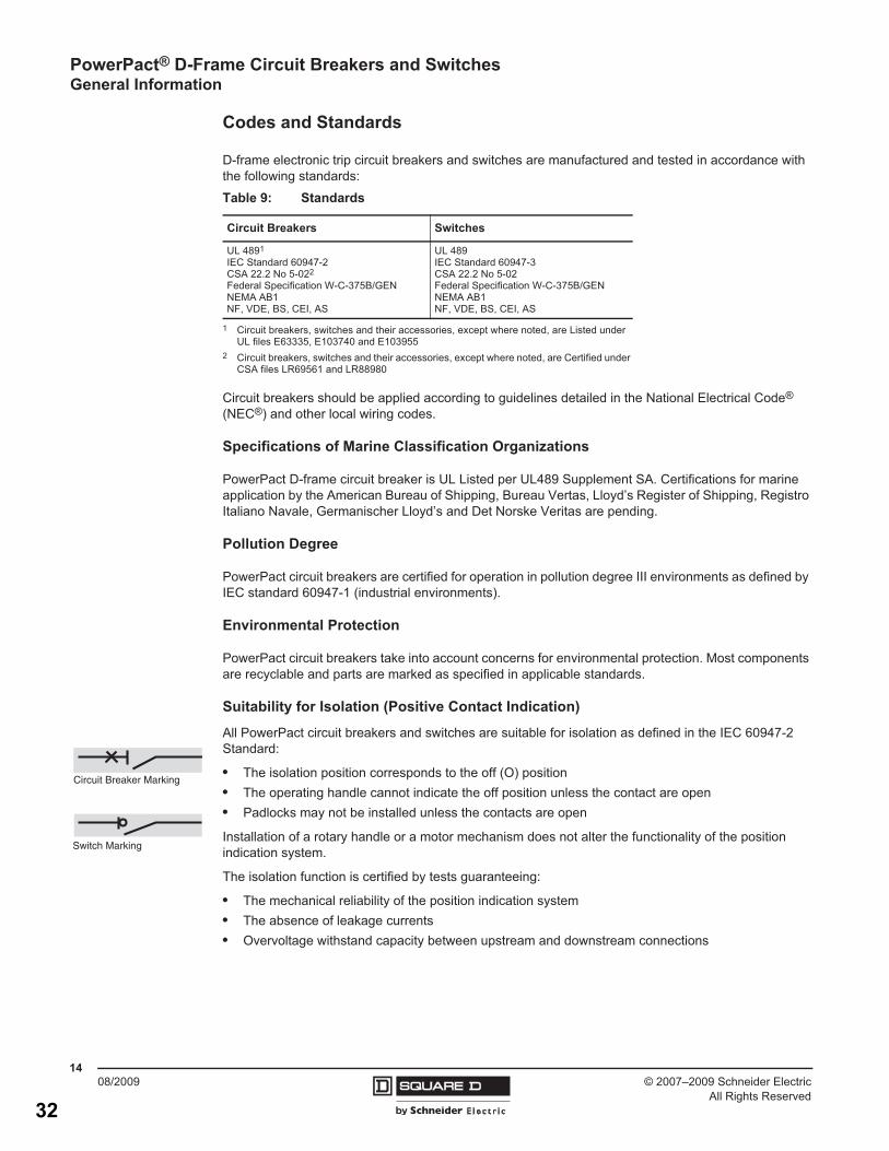
Codes and Standards
D-frame electronic trip circuit breakers and switches are manufactured and tested in accordance with the following standards:
Circuit breakers should be applied according to guidelines detailed in the National Electrical Code® (NEC®) and other local wiring codes.
Specifications of Marine Classification Organizations
PowerPact D-frame circuit breaker is UL Listed per UL489 Supplement SA. Certifications for marine application by the American Bureau of Shipping, Bureau Vertas, Lloyd’s Register of Shipping, Registro Italiano Navale, Germanischer Lloyd’s and Det Norske Veritas are pending.
Pollution Degree
PowerPact circuit breakers are certified for operation in pollution degree III environments as defined by IEC standard 60947-1 (industrial environments).
Environmental Protection
PowerPact circuit breakers take into account concerns for environmental protection. Most components are recyclable and parts are marked as specified in applicable standards.
Suitability for Isolation (Positive Contact Indication)
All PowerPact circuit breakers and switches are suitable for isolation as defined in the IEC 60947-2 Standard:
• The isolation position corresponds to the off (O) position• The operating handle cannot indicate the off position unless the contact are open• Padlocks may not be installed unless the contacts are open
Installation of a rotary handle or a motor mechanism does not alter the functionality of the position indication system.
The isolation function is certified by tests guaranteeing:
• The mechanical reliability of the position indication system• The absence of leakage currents• Overvoltage withstand capacity between upstream and downstream connections
Table 9: Standards
Circuit Breakers Switches
UL 4891
IEC Standard 60947-2 CSA 22.2 No 5-022
Federal Specification W-C-375B/GENNEMA AB1NF, VDE, BS, CEI, AS
1 Circuit breakers, switches and their accessories, except where noted, are Listed under UL files E63335, E103740 and E103955
2 Circuit breakers, switches and their accessories, except where noted, are Certified under CSA files LR69561 and LR88980
UL 489IEC Standard 60947-3CSA 22.2 No 5-02Federal Specification W-C-375B/GENNEMA AB1NF, VDE, BS, CEI, AS
Circuit Breaker Marking
Switch Marking
32

PowerPact® D-Frame Circuit Breakers and SwitchesElectronic Trip Units
1708/2009© 2007–2009 Schneider Electric
All Rights Reserved
Section 2—Electronic Trip Units
Trip Units for PowerPact® D-Frame Circuit Breakers
PowerPact D-frame circuit breakers are equipped with current sensors and an STR electronic trip unit. Current sensors are available in two different sizes:
• 400 A frame—150, 250 and 400 A versions• 600 A frame—600 A version
STR trip units provide protection for loads, from 60 to 600 A:
• STR23SP and STR53UP for standard protection can be mounted on all circuit breakers• Trip unit STR53UP offers a greater number of optional indication and measurement functions,
protection settings and ground-fault protection• STR23SP-OSN for oversized neutral protection (factory-installed only)• STR53UP for generator supplied network protection and long cable runs• STR23SP and STR53UP trip units are available on 4P circuit breakers with sealable, three-position
neutral protection setting:
— 4P 3D (no neutral protection)— 4P 3D + N/2 (neutral protection at 0.5 x Ir) where Ir is trip unit current setting— 4P 4D (neutral protection at Ir) where Ir is trip unit current setting.
33

© 2007–2009 Schneider ElectricAll Rights Reserved
PowerPact® D-Frame Circuit Breakers and Switches Electronic Trip Units
1808/2009
Table 12: Trip Units
STR23SP STR53UP
Overload Protection (Long-Time)
Tripping Threshold (A) In 20–70°C Adjustable (48 Settings)
0.4–1 x InAdjustable (32 Settings)0.4–1 x In
Tripping Time (s)(Min–Max)
— Fixed AdjustableAt 1.5 x Ir 120–180 17–25 34–50 69–100 138–200 277–400
At 6 x Ir 5–7.5 0.8–1 1.6–2 3.2–4 6.4–8 12.8–16
At 7.2 x Ir 3.2–5.0 0.5–0.7 1.1–1.4 2.2–2.8 4.4–5.5 8.8–11
Short-Circuit Protection (Short Time)
TrippingIM/ISD Adjustable (7 Settings) 2–9 x Ir Adjustable (7 Settings) 1.5–7 x Ir
Accuracy ± 15%
Time Delay(ms)
Max. Overcurrent Time Before Tripping Fixed � 40Adjustable (4 Settings + Constant I2t Function)
� 15 � 60 � 140 � 230
Total Breaking Time � 60 � 60 � 140 � 230 � 350
Short-Circuit Protection (Instantaneous)
Tripping Threshold (A) Fixed � 9 x In Adjustable (7 Settings) 1.5–7 x Ir
Adjustable Neutral Protection (Three Position Switch) (STR23SP OSN1 only)
Switch Settings Protection Level
Position 1 4P 3D No Neutral Protection —
Position 2 4P 3D + N/2 0.5 x Ir —
Position 3 4P 4D 1.0 x Ir —
Electronic Trip Unit (Field Replaceable)
Trip Unit2 Trip Function Suffix Cat. No.Long-Time, Short-Time and Fixed Instantaneous Protection STR23SP LS E20 36940
Long-Time, Short-Time, Instantaneous Protection and Options
STR53UP-F LSI E53 36942STR53UP-FT LSIG E54 36943STR53UP-FI LSI E58 36944STR53UP-FTI LSIG E59 36945Communication Wiring — — 32441Replacement Battery — — 32434
1 Oversized Neutral2 F - Fault Indicator; T = Residual-Type Ground-Fault Protection; I = Ammeter
34

PowerPact® D-Frame Circuit Breakers and SwitchesElectronic Trip Units
1908/2009© 2007–2009 Schneider Electric
All Rights Reserved
Electronic Trip Unit STR23SP and SR23SP-OSN (Oversized Neutral)
Protection
• Long-time (LT) overload protection, adjustable threshold, based on the actual RMS current:— Adjustable threshold (2) using six Io base settings (0.5–1) and fine adjustment Ir with eight
settings (0.8–1)— Non-adjustable tripping time (2)
• Short-time (ST) short-circuit protection:— Adjustable threshold Im (3)— Fixed time delay (4)
• Instantaneous (I) short-circuit protection, fixed threshold (5)• Neutral protection available on standard 4P circuit breakers; protection level controlled using three-
position switch:— 4P 3D: no protection of neutral— 3D + N/2: neutral protection at 0.5 Ir— 4P 4D: neutral protection at Ir
• Neutral protection for STR23SP-OSN (oversized neutral) available on four-pole circuit breakers equipped with oversized neutral protection; protection level controlled using three-position switch:— 4P 3D: no protection of neutral— 3D + N/2: neutral protection at 0.75 x Ir— 4P 4D: neutral protection at 1.5 x Ir
Indications
Load indication (LED) in front (6):
• Lights solid at 90% of Ir threshold• Flashes at > 105% or greater of Ir threshold
Test
Test connector in front (7) allows connection to the test kit, to check circuit breaker operation after fitting the trip unit or other accessories.
Setting Example
Question: what is the overload protection threshold of a 400 A D-frame circuit breaker equipped with trip unit STR23SP where Io - 0.5 and Ir - 0.8?
I
t
0
1
3
5
Ir Im
2
4ImIr
STR 23 SP
x Io
-test
+
90105 %Iralarm
x In
7 1 36
.5
.63.7
.91
.8.85
.9.95
1
.88.93
.98
.8
234
5 67
9
x Ir
Io = sensorIr
long timeIm
short time
0615
3065
Definitions
I = Current
In = Nominal Current = Sensor Rating
Io = Course Adjustment x In
Ir = Long-Time (LT) Pickup x Io
Im = Short-Time (ST) Pickup x Ir
35

© 2007–2009 Schneider ElectricAll Rights Reserved
PowerPact® D-Frame Circuit Breakers and Switches Electronic Trip Units
2008/2009
Answer: In x Io x Ir = 400 x 0.5 x 0.8 = 160 A
The same trip unit with the same settings, mounted on a 600 A frame circuit breaker, will have the following tripping threshold: In x Io x Ir = 600 x 0.5 x 0.8 = 240 A.
Electronic Trip Unit STR53UP
Protection
• Long-time (LT) overload protection, adjustable threshold, based on actual rms current, as defined by IEC 60947-2, appendix F:
— Adjustable threshold (1) using six Io base settings (0.5–1) and fine adjustment Ir with eight settings ranging (0.8–1)
— Adjustable tripping time (2)
• Short-time (ST) short-circuit protection:
— Adjustable threshold Isd (3)— Adjustable time delay (4), with or without constant I2t function
• Instantaneous (Ii) short-circuit protection, adjustable threshold (5)• Neutral protection available on standard 4P circuit breakers; protection level controlled using three-
position switch:
— 4P 3D: no protection of neutral— 3D + N/2: neutral protection at 0.5 Ir— 4P 4D: neutral protection at Ir
Overload Indications (%Ir)
• LED (9) lights solid when current exceeds 0.9 Ir• LED (9) flashes when current exceeds long-time threshold Ir
Fault Indications
LEDs indicate the type of fault that caused tripping:
• Overload (LT protection) or abnormal component temperature (> Ir)• Short-circuit (ST or instantaneous protection) (> Isd)• Ground-fault (if ground-fault protection option is present) > Ig• Microprocessor malfunction—both (> Ir and > Isd) LEDs go on, plus the > Ig LED, if the ground
fault protection option is present
The LEDs are battery powered with spare batteries supplied in the adapter box. When a fault occurs, the LED indicating type of fault shuts off after approximately 10 minutes to conserve battery power.
> Ih
> Im
> Ir
μ P
testSTR 53 UP
Io
x In
-test
+
31 2 4 5
(s) @ 6 Ir
.3 .3.2
.1
0
.2
.1
0on I2t off
.90 .93.95
.98
1
.88
.85
.8
.8 .9
1
.7
.6
.5
1.5 .6
.7
.8
1
.4
.3
.2x Io
Ir Isd
x Ir
Ii
x In
Ig
x In
tr tsd(s) .4 .4
.3
.2
.1
.3
.2
.1on I2t off
tg(s)
%Ir >Ir >Isd >Ig
A
In I1 I2 I3 IsdIr li
tr
tsd
6 9
8
8
4
2
0,5
4 56
7
7
3
2
1.5
4 68
9
9
3
2
1.5
Ir Isd I I
t
0
8 71
2
3
4
5
6
7
0615
3067
Definitions
I = Current
In = Nominal Current = Sensor Rating
Io = Course Adjustment x In
Ir = Long-Time (LT) Pickup x Io
Im = Short-Time (ST) Pickup x Ir
Isd = Instantaneous Pickup
Ig = Ground-Fault Pickup
36

Industrial Generator Set Accessories
Standard Features
� The line circuit breaker interrupts the generator set
output during a short circuit and protects the wiring
when an overload occurs. Use the circuit breaker to
manually disconnect the generator set from the load
during generator set service.
� Circuit breaker kits are mounted to the generator set
and are available standard with load-side lugs or
bus bars and neutral bus bar.
� Kohler Co. offers a wide selection of molded-case
line circuit breaker kits including single and dual
configurations for each generator set.
� Four types of line circuit breakers are available:
� Magnetic trip
� Thermal magnetic trip
� Electronic trip
� Electronic with Ground Fault Circuit Interruption
(GFCI) trip
� In addition, line circuit breakers are offered with 80%
and 100% ratings (thermal magnetic available only
in 80% rating).
� Single line circuit breaker kits allow circuit protection
of the entire electrical system load.
� Dual line circuit breaker kits allow circuit protection
of selected priority loads from the remaining
electrical system load.
� Line circuit breakers comply with the following codes
and standards unless otherwise stated.
� UL 489 Molded Case Circuit Breakers
� UL 1077 Supplementary Protectors
� UL 2200 Stationary Engine Generator Assemblies
Line Circuit Breakers 20--2250 kW
Dual Circuit Breaker Kit with Neutral Bus Bar
20--300 kW Model Shown
Single Circuit Breaker Kit with Neutral Bus Bar
20--300 kW Model Shown
G6-88 9/10d
Line Circuit Breakers 20--2250 kW
37

G6-88 9/10d
Line Circuit Breaker Types
Magnetic Trip
The magnetic trip features an electromagnet in series with the
load contacts and a moveable armature to activate the trip
mechanism. When a sudden and excessive current such as a
short circuit occurs, the electromagnet attracts the armature
resulting in an instantaneous trip (UL 1077 circuit breakers).
Thermal Magnetic Trip
Thermal magnetic trip contains a thermal portion with a
bimetallic strip that reacts to the heat produced from the load
current. Excessive current causes it to bend sufficiently to trip
the mechanism. The trip delay is dependant on the duration
and excess of the overload current. Elements are factory-
calibrated. A combination of both thermal and magnetic
features allows a delayed trip on an overload and an
instantaneous trip on a short circuit condition.
Electronic Trip
These line circuit breakers use electronic controls and miniature
current transformers to monitor electrical currents and trip when
preset limits are exceeded.
Electronic with Ground Fault Trip
The ground fault trip feature is commonly referred to as Ground
Fault Circuit Interruption (GFCI). Models with GFCI compare
current flow in phase and neutral lines, and trip when current
unbalance exists.
Ground fault trip units are an integral part of the circuit breaker
and are not available as field-installable kits. The ground fault
pickup switch sets the current level at which the circuit breaker
will trip after the ground fault delay. Ground fault pickup values
are based on circuit breaker sensor plug only and not on the
rating plug multiplier. Changing the rating plug multiplier has no
effect on the ground fault pickup values.
80% Rated Circuit Breaker
Most molded-case circuit breakers are 80% rated devices. An
80% rated circuit breaker can only be applied at 80% of its
rating for continuous loads as defined by NFPA 70. Circuit
conductors used with 80% rated circuit breakers are required to
be rated for 100% of the circuit breaker’s rating.
The 80% rated circuit breakers are typically at a lower cost than
the 100% rated circuit breaker but load growth is limited.
100% Rated Circuit Breaker
Applications where all UL and NEC restrictions are met can use
100% rated circuit breakers where 100% rated circuits can carry
100% of the circuit breaker and conductor current rating.
The 100% rated circuit breakers are typically at a higher cost
than the 80% rated circuit breaker but have load growth
possibilities.
When applying 100% rated circuit breakers, comply with the
various restrictions including UL Standard 489 and NEC
Section 210. If any of the 100% rated circuit breaker restrictions
are not met, the circuit breaker becomes an 80% rated circuit
breaker.
Accessories
� Alarm Switch
The alarm switch indicates that the circuit breaker is in a tripped
position caused by an overload, short circuit, ground fault, the
operation of the shunt trip, an undervoltage trip, or the push-to-
trip pushbutton. The alarm resets when the circuit breaker is
reset.
� Auxiliary Contacts
These switches send a signal indicating whether the main
circuit breaker contacts are in the open or closed position.
� Bus Bars (units without circuit breakers installed)
Bus bar kits are available on alternators with leads for
connection to the generator set when circuit breakers are not
ordered. Bus bar kits offer a convenient way to connect load
leads to the generator set when a circuit breaker is not present.
� Ground Fault Annunciation
A relay contact for customer connection indicates a ground fault
condition and is part of a ground fault alarm.
� Lockout Device (padlock attachment)
This field-installable handle padlock attachment is available for
manually operated circuit breakers. The attachment can
accommodate three padlocks and will lock the circuit breaker in
the OFF position only.
� Neutral Lugs
Various neutral lug sizes are available to accommodate multiple
cable sizes for connection to the bus bar only.
� Overcurrent Trip Switch
The overcurrent trip switch indicates that the circuit breaker has
tripped due to overload, ground fault, or short circuit and returns
to the deenergized state when the circuit breaker is reset.
� Undervoltage Trip, 12 VDC or 24 VDC
The undervoltage trips the circuit breaker when the control
voltage drops below the preset threshold of 35%--70% of the
rated voltage.
� Shunt Trip, 12 VDC or 24 VDC
A shunt trip option provides a solenoid within the circuit breaker
case that, when momentarily energized from a remote source,
activates the trip mechanism. This feature allows the circuit
breaker to be tripped by customer-selected faults such as
alternator overload or overspeed. The circuit breaker must be
reset locally after being tripped. Tripping has priority over
manual or motor operator closing.
� Shunt Trip Wiring
Connects the shunt trip to the generator set controller.
Line Circuit Breaker Types
100% Rated Circuit BreakerElectronic Trip
38

G6-88 9/10d
Line Circuit Breaker Specifications
80% Rating Circuit Breaker
Gen. Set
kW
Alt.
Model
Ampere
Range Trip Type
C. B.
Frame
Size
20--60 4P/4Q
30--100
Magnetic, UL 1077
E
(480 V
max.)
Magnetic, UL 1077
with 12 V shunt trip
Magnetic, UL 1077
with 24 V shunt trip
15--150 Thermal magnetic H
175--250 Thermal magnetic J
60--180 4S/4V
30--100
Magnetic, UL 1077
E
(480 V
max.)
Magnetic, UL 1077
with 12 V shunt trip
Magnetic, UL 1077
with 24 V shunt trip
15--150 Thermal magnetic H
175--250 Thermal magnetic J
300--400 Thermal magnetic L
600
Electronic
D
Electronic GFCI
700--800 Thermal magnetic M
800 Electronic
P
800 Electronic GFCI
200--300 4UA
15--150 Thermal magnetic H
175--250 Thermal magnetic J
300--400 Thermal magnetic L
600
Electronic
D
Electronic GFCI
700--800 Thermal magnetic M
1000--1200 Thermal magnetic P
800--1200 Electronic
P
800--1200 Electronic GFCI
350--900
(small ext.
box)
(no 5M4044)
4M/5M
w/leads
300--400 Thermal magnetic L
600
Electronic
D
Electronic GFCI
700--800 Thermal magnetic M
1000--1200 Thermal magnetic P
800--1200
Electronic
P
Electronic GFCI
350--900
(large ext.
box) (no
5M4044) *�
4M/5M
w/leads1600--2500
Thermal magnetic
RElectronic
Electronic GFCI
1000-- 2250
and 900 kW
with 5M4044
(large
ext. box) *�
5M/7M
w/bus
bars
1200--2500
Thermal magnetic
RElectronic
Electronic GFCI
* Available as front or rear facing circuit breaker on junction box.
Front facing circuit breakers are not available on the
600--2000REOZM, 600--2000REOZMB, and 400--800RZW models
� Front facing circuit breakers for 450/500REOZVB models are available
for units with standard air cleaner and not with heavy-duty air cleaner.
� The 5M4044 is a 4-bus alternator and has bus-type mounting.
� Contact the factory for this rating.
100% Rating Circuit Breaker
Gen. Set kW
Alt.
Model
Ampere
Range Trip Type
C. B.
Frame
Size
20--60 4P/4Q 150--400
Electronic
D
Electronic GFCI
60-180 4S/4V
150--400
Electronic
D
Electronic GFCI
600--800
Electronic
P
Electronic GFCI
200--300 4UA
150--400
Electronic
D
Electronic GFCI
600--1200
Electronic
P
Electronic GFCI
350--900
(small ext. box)
(no 5M4044)
4M/5M
w/leads
150--400
Electronic
D
Electronic GFCI
600--1200
Electronic
P
Electronic GFCI
350--900
(large ext. box)
(no 5M4044) *�
4M/5M
w/leads
1600--2500
Electronic
R
Electronic GFCI
3000
Electronic
NW
Electronic GFCI
1000-- 2250 and
900 kW with
5M4044 (large
ext. box) *�
5M/7M
w/bus
bars
1200--2500
Electronic
R
Electronic GFCI
3000
Electronic
NW
Electronic GFCI
Circuit Breaker Lugs Per Phase (Al/Cu)
Frame Size Ampere Range Wire Range
E
(480 V max.)30--100
Up to two wire terminals fitting
10-32 or 1/4-20 stud
H 15--150 One #14 to 3/0
J
175 One 1/0 to 4/0
200--250 One 3/0 to 350 kcmil
L 300--400 One #1 to 600 kcmil Al
D
150--400
One #2 to 500 kcmil Al
One #2 to 600 kcmil Cu
600
Two 2/0 to 500 kcmil Al
Two 2/0 to 350 kcmil Cu
M 700-800 Three 3/0 to 500 kcmil
P
600-800 Three 3/0 to 500 kcmil
1000-1200 Four 3/0 to 500 kcmil
R 1600-2500 (8) lugs per phase rated for
(1) #4--600 kcmil or
(2) 1/0--250 kcmilNW 2500/3000
Interrupting Ratings
Interrupting Rating
Code
240 Volt,
kA
480 Volt,
kA
600 Volt,
kA
B 10 — —
D 25 18 14
G 65 35 18
J 100 65 25
K (except P Frame) 65 � 65 � 65 �
K (P Frame) 65 � 50 � 50 �
L (except NW Frame) 125 � 100 � 50 �
H (NW Frame) 100 � 100 � 85 �
L (NW Frame) 200 � 150 � 100 �
Line Circuit Breaker Specifications
D350--900
M/5M
150--400
Electronic
D
150--400
39

© 2007, 2010 by Kohler Co. All rights reserved.
DISTRIBUTED BY:
G6-88 9/10d
Line Circuit Breaker Applications
Single Circuit Breaker Installations
A generator set with a single circuit breaker installed typically
feeds a single transfer switch and then a distribution panel.
This allows protection of the entire system.
To Remaining
Building Loads
To Priority Load(s)
Line C.B.
Single line circuit breaker configuration where circuit breaker trip
can trip causing all power to building loads including priority load
to be disrupted.
ATS
Distribution
Panel
Distribution
Panel
Dual Circuit Breaker Installations
A generator set with dual circuit breakers installed is used to
segregate critical loads. Typically, one circuit breaker will feed a
main transfer switch with noncritical loads and the other circuit
breaker will feed a second transfer switch that feeds critical
loads.
To Remaining
Building Loads
To Priority Load(s)
First
Line C.B.
Second
Line C.B.
Dual line circuit breaker configuration where first circuit breaker
can trip allowing second circuit breaker to continue supplying
power to priority load(s).
ATS ATS
Distribution
Panel
Distribution
Panel
Dual Circuit Breaker Combinations
Alternator
Model
First
C. B. Frame
Size
Second
C. B. Frame
Size Comments
4P/4Q/4S/
4V/4UA
H —
J —
4S/4V/4UA L —
4P/4Q/4S/
4V/4UAD —
100% rating, standard or
GFCI
4S/4V/4UA
M —
P —
100% rating, standard or
GFCI
4P/4Q/4S/
4V/4UA
H H
J H or J
4S/4V/4UA L H, J, or L
4P/4Q/
4S/4VD H, J, L, or D 100% rating, no GFCI
4UA D H, J, L, or D
Primary or sec. available as
100% rating, std. or GFCI
Alternator
Model
First
C. B. Frame
Size
Second
C. B. Frame
Size Comments
4S/4V M H, J, L, or D 100% rating, no GFCI
4UA M H, J, L, or D D available as GFCI
4S/4V P H, J, L, or D 100% rating, no GFCI
4UA
P H, J, L, or D
P and/or D available as
GFCI
P P 100% rating, no GFCI
4M/5M/7M All —
Dual circuit breaker
configurations available as
Engineered Specials
KOHLER CO., Kohler, Wisconsin 53044 USA
Phone 920-457-4441, Fax 920-459-1646
For the nearest sales and service outlet in the
US and Canada, phone 1-800-544-2444
KohlerPower.com
Availability is subject to change without notice. Kohler Co. reserves the
right to change the design or specifications without notice and without any
obligation or liability whatsoever. Contact your local Kohler� generator set
distributor for availability.
Kohler Power Systems
Asia Pacific Headquarters
7 Jurong Pier Road
Singapore 619159
Phone (65) 6264-6422, Fax (65) 6264-6455
Line Circuit Breaker Applications
40

PowerPact® D-Frame Circuit Breakers and SwitchesTrip Curves
5908/2009© 2007–2009 Schneider Electric
All Rights Reserved
Section 11—Trip Curves
STR23SP STR53UP10 000
5 000
2 000
1 000
500
200100
50
20
10
5
2
1.5
.2
.1.05
.02
.01
.005
.002
.001.5 .7 1 2 3 4 5 7 10 20 30 50 70100 200300
t(s)
I / Ir
I = 11 x In
Ir = 0.4–1 x In
Im = 2–9 x Ir
Reflex Tripping:t < 10 ms
0615
3218 10 000
5 000
2 000
1 000
500
200100
50
20
10
5
2
1.5
.2
.1.05
.02
.01
.005
.002
.001.5 .7 1 2 3 4 5 7 10 20 30 50 70100 200300
I / Ir
Tsd = 0–0.3 s
Reflex Tripping:t < 10 ms
Isd = 1.5I2t = OFF
Isd = 1.5I2t = ON
Ir = 0.4–1 x Intr = 1–8 s (6 Ir)
For Hot Start (0.9 x Ir) DivideMax. Time by 2, Min. Time by 4
Isd = 1.5–7 x Ir
Ii = 1.5–9 x in
t(s)
0615
3219
41

42

Remote Annunciator RSA II
for Kohler� Controllers
� Monitors the generator set equipped with one of the following
controllers:
Decision-Maker� 550 Software Version 2.10 and higher
Decision-Maker� 3+ Software Version 1.13 and higher
KPC 1000 Version 1.37 and higher
� Allows monitoring of the common alarm, remote testing of the
automatic transfer switch, and monitoring of the normal/
emergency source with one of the following controllers:
MPAC� 1000 Version 1.27 and higher
MPAC� 1500 Version 1.00 and higher
� Configuration via a personal computer (PC) software.
� RSA II panel includes writable surfaces (four white boxes in
illustration) for user-defined selections.
� Uses Modbus� protocol, an industry standard.
� Controller connections:
RS-485 for serial bus network
USB device port for PC
12-/24-volt DC power supply
120/208 VAC power supply (available accessory)
� Meets the National Fire Protection Association Standard
NFPA 110, Level 1.
Dimensions
� Dimensions—W x H x D, mm (in.). Also fits in a standard
203 mm x 203 mm (8 in. x 8 in.) Hoffman box.
Surface Mounted:
203 x 203 x 56 (8.0 x 8.0 x 2.2)
Flush Mounted:
203 x 203 x 58 (8.0 x 8.0 x 2.3)
Flush mounting plate W1: 229 (9.0)
Modbus� is a registered trademark of Schneider Electric.
Industrial Generator Set Accessories
Remote Annunciator (RSA II)
Surface Mounted Flush Mounted
WW
W1
D
D
H
H
RSA II
RSA II with ATS Controls
Failure
N
/Aux.
G6-95 2/09b
Remote Annunciator (RSA II)
43

G6-95 2/09b
Fault and Status Conditions Fault LEDs Fault Horn
System
Ready LED
Generator
Running LED
Communication
Status LED
Overcrank Shutdown Red On Red Off Green
High Engine Temperature Warning * Yellow On Red Green Green
High Engine Temperature Shutdown Red On Red Off Green
Low Oil Pressure Warning * Yellow On Red Green Green
Low Oil Pressure Shutdown Red On Red Off Green
Overspeed Shutdown Red On Red Off Green
Emergency Stop * Red On Red Off Green
Low Coolant Level/Aux. Shutdown Red On Red Off Green
Low Coolant Temperature * Yellow On Red Off Green
Low Cranking Voltage Yellow On Red Off Green
Low Fuel—Level or Pressure * Yellow On Red Green or Off Green
Not-In-Auto Red On Red Green or Off Green
Common Fault Red On Green Green or Off Green
Battery Charger Failure (550 controller) * Yellow On Red Green or Off Green
Battery Charger Failure (16-light controller) * Yellow On Green Green or Off Green
High Battery Voltage * Yellow Off Green Green or Off Green
Low Battery Voltage * Yellow Off Green Green or Off Green
User Input #1 (Warning) Yellow Off Green Green or Off Green
User Input #1 (Shutdown) Red On Green Off Green
User Input #2 (Warning) Yellow Off Green Green or Off Green
User Input #2 (Shutdown) Red On Green Off Green
User Input #3 (Warning) (550 controller) � Yellow Off Green Green or Off Green
User Input #3 (Shutdown) (550 controller) � Red On Green Off Green
EPS Supplying Load Yellow Off Green Green Green
Communications Status (Fault mode) — Off Green or Red Green or Off Red
ATS Fault (RSA II with ATS Controls only) Red On Red or Yellow Green or Off Green
Green LEDs appear as steady on when activated.
Yellow LEDs slow flash when activated except steady on with EPS supplying load and high battery voltage.
Red LEDs slow flash when activated except fast flash with loss of communication and not-in-auto.
Specifications
� LED indicating lights for status, warning, and/or shutdown.
See the above chart for details.
� Power source with circuit protection: 12- or 24-volt DC
� Power source with120/208 VAC, 50/60 Hz adapter (option)
� Power draw: 200 mA
� Humidity range: 0% to 95% noncondensing
� Operating temperature range: --20°C to +70°C
(--4°F to +158°F)
� Storage temperature range: --40°C to +85°C
(--40°F to +185°F)
� Standards:
� NFPA 110, level 1
� UL 508 recognized
� CE directive
� NFPA 99
� EN6II-4-4 fast transient immunity
� RS-485 Modbus� isolated port @ 9.6/19.2/38.4/57.6 kbps
(default is 19.2 kbps)
� USB device port
� NEMA 2 enclosure
ATS Controls (RSA II with ATS controls only)
� ATS position LED (normal or emergency)
� Power source indicator LED (normal or emergency)
� ATS fault LED
� Key-operated spring-loaded test switch
(Re-Transfer/Auto/Test)
NFPA Requirements
� NFPA 110 compliant
� Engine functions:
� High battery voltage warning *
� High engine temperature shutdown
� High engine temperature warning *
� Low battery voltage warning *
� Low coolant level/aux. shutdown
� Low coolant temperature warning *
� Low cranking voltage
� Low fuel warning (level or pressure) *
� Low oil pressure shutdown
� Low oil pressure warning *
� Overcrank shutdown
� Overspeed shutdown
� General functions:
� Audible alarm silence
� Battery charger fault *
� Lamp test
� Master switch not-in-auto
* May require optional kit or user-provided device to enable function and
LED indication.
� Digital input #3 is factory-set for high battery voltage on the 16-light
controller.
Modbus� is a registered trademark of Schneider Electric.
44

G6-95 2/09b
Fault and Status LEDs and Lamp Test Switch
Alarm Horn. Horn sounds giving a minimum 90 dB at
0.1 m (0.3 ft.) audible alarm when a warning or shutdown
fault condition exists except on high/low battery voltage or EPS
supplying load.
Alarm Silenced. Red LED lights when alarm horn is
deactivated by alarm silence switch (lamp test switch).
Alarm Silence Switch. Switch quiets the alarm during
servicing. The horn will reactivate upon additional faults.
ATS Fault. Red LED lights when ATS fails to transfer.
Aux. See Low Coolant Level/Aux.
Battery Charger Failure. LED lights if battery charger
malfunctions. Requires battery charger with alarm contact.
(High/Low) Battery Voltage. LED flashes if battery or
charging voltage drops below preset level. LED lights steady
if battery voltage exceeds preset level.
Common Fault. LED lights when a single or multiple
common faults occur.
Communication Status. Green LED lights indicating
annunciator communications functional. Red LED indicates
communication fault.
Emergency Power System (EPS) Supplying Load. LED
lights when the generator set is supplying output current (550
controller) or when transfer switch is in the emergency position
(16-light controller).
Emergency Stop. LED lights and engine stops when
emergency stop is made. May require a local emergency
stop switch on some 16-light controllers.
Generator Running. LED lights when generator set is in
operation.
(Generator Switch) Not In Auto. LED lights when generator
set master switch is in RUN or OFF/RESET position.
High Engine Temperature. Red LED lights if engine has shut
down because of high engine coolant temperature. Yellow
LED lights if engine coolant temperature approaches shutdown
range. Requires warning sender on some models.
Lamp Test Switch. Switch tests all the annunciator indicator
LEDs and horn.
Low Coolant Level. LED lights when engine coolant level is
below acceptable range on radiator-mounted generator sets
only. When used with a 16-light controller, the LED indicates
low coolant level or an auxiliary fault shutdown. Requires user-
supplied low coolant level switch on remote radiator models.
Low Coolant Temperature. LED lights if optional engine block
heater malfunctions and/or engine coolant temperature is too
low. Requires prealarm sender on some models.
Low Cranking Voltage. LED lights if battery voltage drops
below preset level during engine cranking.
Low Fuel (Level or Pressure). LED lights if fuel level in tank
approaches empty with diesel models or fuel pressure is low on
gas models. Requires customer-supplied switch.
Low Oil Pressure. Red LED lights if generator set shuts down
because of insufficient oil pressure. Yellow LED lights if engine
oil pressure approaches shutdown range. Requires warning
sender on some models.
Overcrank. LED lights and cranking stops if engine does not
start in either continuous cranking or cyclic cranking modes.
Overspeed. LED lights if generator set shuts down because of
overspeed condition.
System Ready. Green LED lights when generator set master
switch is in AUTO position and the system senses no faults.
Red LED indicates system fault.
User-Defined Digital Inputs #1, #2, and #3. Monitors three
digital auxiliary inputs (status, warnings, and/or shutdowns).
Individual red LEDs flash when a fault occurs or the status
changes. User-defined digital input #1 and #2 are selected via
the RSA II master for local or remote (generator set or ATS).
The user-defined digital input can be assigned at the controller
or via PC software.
16-Light Controller. When remote, digital input #1 and #2
are tied to the communication module. When local, they are
tied directly to the RSA II master. Digital input #3 is factory-set
for high battery voltage.
550 Controller. When remote, digital inputs #1, #2, and #3
are tied to controller digital inputs (D7, D8, and D10). When
local, user-defined digital inputs #1 and #2 are tied directly to
the RSA II master. Input #3 can only be configured for local or
remote (generator set).
Communications (Shown with RSA II with ATS Controls)
Local Single (Master) Connection
A single RSA II connects directly to the controller’s
communication port with an RS-485 cable.
Generator set
controller
Remote
annunciator
(master)
PC
(user-supplied)Use RS-485, see Note*
Available on 550 controller
with KBus only
Communication
Module
(16-light only)
Transfer Switch
Use RS-485,
see Note*
Local Multiple (Master/Slave) Connections
A single RSA II master connects directly to the controller’s
communication port with an RS-485 cable. Additional RSA IIs
(slaves) can connect to the single master RSA II. Status of the
RSA II (master) is annunciated on the RSA II (slave) panel.
Communication
Module
(16-light only)
Generator set
controller
Remote
annunciator
(master)
Remote
annunciator
(slave)
Remote
annunciator
(slave)
Transfer Switch
Use RS-485,
see Note*
Use RS-485,
see Note*
Note*: Use RS-485 for a total of up to 1220 m (4000 ft.) maximum from the first device to the last device.
45

© 2009, 2009 by Kohler Co. All rights reserved.
DISTRIBUTED BY:
G6-95 2/09b
Modbus�/Ethernet, Single Master or Multiple Master/Slave Connections
(Shown with RSA II with ATS Controls)
An RSA II master communicates with a controller and RSA II
slaves through an Ethernet network. A Modbus�/Ethernet
converter is required for each RSA II and controller. RS-485
cable connects the RSA II to the converter. Category 5e (Cat
5e) network cable connects the Modbus�/Ethernet converter to
the Ethernet.
Note: When combining RSA II remote annunciators with the
RSA 1000 it is permissible provided that the master
remote annunciator is a RSA II remote annunciator.
Note*: UseRS-485 for a total of up to 1220 m (4000 ft.) maximum
from the first device to the last device.
Generator set
Controller
Remote Annunciator
(Master)
Communication
Module
(16-light only)
Ethernet
Remote Annunciator
(Slave)
Modbus�/Ethernet
Converter
Modbus�/Ethernet
Converter
Remote Annunciator
(Slave)
Modbus�/Ethernet
Converter
Transfer
Switch
Modbus�/Ethernet
Converter
Use RS-485,
see Note*
Use RS-485,
see Note*
Use RS-485,
see Note*
Use RS-485,
see Note*
Use RS-485,
see Note*
Accessories
� Power source adapter kit 120/208 VAC, 50/60 Hz.
� Modbus�/Ethernet converter GM41143-KP2 for serial to
Ethernet communication.
� Communication module GM32644-KA1 or GM32644-KP1 is
required with Decision-Maker� 3+ controllers.
Modbus� is a registered trademark of Schneider Electric.
Kohler Power Systems
Asia Pacific Headquarters
7 Jurong Pier Road
Singapore 619159
Phone (65) 6264-6422, Fax (65) 6264-6455
Availability is subject to change without notice. Kohler Co. reserves the
right to change the designor specificationswithout noticeandwithoutany
obligation or liability whatsoever. Contact your local Kohler� generator
set distributor for availability.
KOHLER CO., Kohler, Wisconsin 53044 USA
Phone 920-565-3381, Fax 920-459-1646
For the nearest sales and service outlet in the
US and Canada, phone 1-800-544-2444
KohlerPower.com
46

Model KCS-DMTD-0260B
Transfer Switch Standard Features• UL 1008 listed at 480 VAC file #E58962 (automatic), #E86894
(nonautomatic)• CSA certification available• IBC seismic certification available• Standard-transition or programmed-transition modes of
operation with either automatic or non-automatic control• Available in 2, 3, or 4 pole configurations• Electrically operated, mechanically held mechanism• Double-throw, mechanically interlocked design (break-before-
make power contacts)• Solid, switched, or overlapping neutral (make-before-break)• High withstand and close-on ratings• Design suitable for emergency and standby applications on all
classes of load, 100% tungsten rated through 400 amps• Standard-transition transfer time less than 100 milliseconds (6
cycles @ 60 Hz)• Silver alloy main contacts• Gold-flashed engine start contacts rated 2 amps @ 30 VDC/250
VAC• Front-accessible contacts for easy inspection• Front-replaceable main and arcing contacts (800-4000 amps)• Reliable, field-proven solenoid mechanism• Switching mechanisms lubricated for life• Internal manual operating handle• Main shaft auxiliary position-indicating contacts (rated 10 amps
@ 32 VDC/250 VAC)• NEMA type 1, 12, 3R, 4, and 4X enclosures available
MPAC® 1500 Controller
Standard Features• Microprocessor-based controller• Environmentally sealed user interface• LCD display, 4 lines x 20 characters, backlit• Dynamic function keypad with tactile feedback pushbuttons
allows complete programming and viewing capability at the door• LED indicators: Source available, transfer switch position,
service required (fault), and “not in auto"• Broadrange voltage sensing (208-600 VAC) on all phases• Phase-to-phase sensing and monitoring with 0.5% accuracy on
both sources• Frequency sensing with 0.5% accuracy on both sources• Anti-single phasing protection• Phase rotation sensing for three-phase systems• Real-time clock with battery backup and automatic adjust for
daylight saving time and leap year• Time-stamped event log• Fail-safe transfer for loaded test and exercise functions• DIP switches: password disable and maintenance• Modbus® RTU and Modbus® TCP/IP protocols• (Modbus® register map available)• RJ45 connector for 10/100 ethernet connection• USB port with read/write compatibility• Isolated RS-485 ports• One-year limited warranty
Programmable Features• Programming and monitoring methods:
o Monitoring and password-protected programming atthe door using the keypad and display
o Program and monitor using a PC with Monitor IIIintegrated generator set and ATS monitoring software
o Transfer files through the USB port• System voltage and frequency• Voltage unbalance• Over/undervoltage and over/underfrequency for all phases of the
normal and emergency sources• Time delays• Load/no load/auto-load test and load/no-load exercise functions• Programmable inputs and outputs• Load control outputs (load stepping)• Selectable operating modes: utility-generator, generator-
generator, or utility-utility• Load bank control for exercise or test• Pre/post-transfer, 9 individual time delays for selected loads• ABC/BAC/none phase rotation selection with error detection• Resettable historical data• In-phase monitor• Password protection, 3 security levels
Model KCS-DMTD-0260B
47

KCS-DMTD-0260B, continued
User Interface LED Indicators• Contactor position: source N and source E• Source available: source N and source E• Service required (fault indication)• Not in automatic mode
LCD Display• System status• Line-to-line voltage• Line-to-neutral voltage• Active time delays• Source frequency• Preferred source selection• System settings• Common alarms• Load current, each phase (requires optional current
transformers)• Inputs and outputs• Faults• Time/date• Address• Event history• Maintenance records• Exerciser schedule• Exerciser mode• Time remaining on active exercise
Dynamic Function Tactile Keypad Operations• Scroll up/down/forward/back• Increase/decrease/save settings• End time delay• Start/end test• Reset fault• Lamp test
DIP Switches• Maintenance mode• Password disable
Event HistoryView up to 99 time and date-stamped events on the display or ona personal computer equipped with optional Monitor III software.Download up to 2000 events with Monitor III software or downloadcomplete event history file to a PC or a memory device connectedto the USB port.
Main Logic Board Inputs and Outputs• Two (2) programmable inputs• Two (2) programmable outputs, isolated form C (SPDT) contacts
rated 1 amp @ 30 VDC, 500 mA @120 VAC
Main Board I/O Specifications Output contact type Isolated form C (SPDT) Output contact rating 1 amp @ 30 VDC, 500 mA
@120 VAC I/O terminals wire size range #12-24 AWG
Communications• USB port with read/write capability• Isolated RS-485 ports• RJ-45 connector for 10/100 ethernet connection• Modbus® RTU and Modbus® TCP/IP protocols (Modbus®
register map available)• USB Port. Upload or download files from a PC or a memory
device through the USB port.o Application software o Event history fileso Language fileso Parameter settingso Usage reportso Feature configuration
USB Data Logger• Time-stamped voltage and frequency readings• Minimum and maximum current and voltage readings for a
selected time period
Programmable Features• System voltage, 208 600 VAC *• System frequency, 50/60 Hz *• Single/three-phase operation *• Standard/programmed-transition operation *• Preferred source selection• Phase rotation: ABC/BAC/none selection with error detection• Voltage and frequency pickup and dropout settings• Voltage unbalance, enable/disable• In-phase monitor: enable/disable and phase angle• Transfer commit/no commit• Source/source mode: utility/gen, gen/gen, utility/utility, or utility/
gen/gen for 3-source systems• Passwords, system and test• Time, date, automatic daylight saving time enable/disable• Time delays (see table)• Exerciser: calendar mode, loaded/unloaded up to 21 events• Test: loaded/unloaded/auto load (1-60 minutes)• Remote test: loaded/unloaded• Automatic override on generator failure (loaded test and
exercise)• Peak shave delay enable/disable• Current monitoring †• Pre/post-transfer, 9 individual time delays for selected loads• Current-based load control settings: high/low current levels and
load add/remove priority for 9 separate loads †• Prime power sequence alternates between two generator sets• Resettable historical data
* System parameters factory-set per order.† Requires optional current sensing kit Modus® is a registered trademark of Schneider Electric.
KCS-DMTD-0260B, continued
48

KCS-DMTD-0260B, continued
Programmable Inputs• External time delay input• External battery fault• External common fault• Inhibit transfer• Load shed to force transfer to OFF (programmed-transition
models only; requires accessory)• Peak shave/area protection input• External test• Three-source system disable
Programmable Outputs• Chicago alarm control• Common alarm events• Contactor position• Exercise active• Failure to acquire standby source• Failure to transfer• Generator engine start, source N and E• I/O module faults• Load bank control• Load control active (pre/post transfer delay, up to 9 outputs)• Loss of phase fault, source N and E• External battery fault• Non-emergency transfer• Not in automatic mode• Over/underfrequency faults, source N and E (generator)• Over/undervoltage faults, source N and E• Peak shave/area protection active• Phase rotation error, source N and E• Preferred source supplying load• Software-controlled relay outputs (4 maximum)• Source available, preferred and standby• Standby source supplying load• Synchronizing output• Test active• Transfer switch auxiliary contact fault• Transfer switch auxiliary contact open• Voltage unbalance
Voltage and Frequency SensingParameter Default Adjustment Range Undervoltage dropout 90% of pickup 75%-98% Undervoltage pickup 90% of nominal 85%-100% Overvoltage dropout * 115% of nominal* 106%-135% Overvoltage pickup 95% of dropout 95%-100% Unbalance enable Disable Enable/Disable Unbalance dropout 20% 5%-20% Unbalance pickup 10% 3%-18% Voltage dropout time 0.5 sec. 0.1-9.9 sec. Underfrequency dropout 99% of pickup 95%-99% Underfrequency pickup 90% of nominal 80%-95% Overfrequency dropout 101% of pickup 101%-115% Overfrequency pickup 110% of nominal 105%-120% Frequency dropout time 3 sec. 0.1-15 sec. * 690 volts, maximum. Default = 110% for 600 volt applications.
Adjustable Time DelaysTime Delays Default Adjustment Range
Engine start, Source S2 3 sec. 0-60 sec. †Engine start, Source S1 (gen/gen)3 sec.Engine cooldown, Source S2 5 sec.
0-60 min.Engine cooldown, S1 (gen/gen) 2 sec.Fail to acquire standby source 1 min.Fail to acquire preferred source 1 min.Transfer, preferred to standby 3 sec.Transfer, standby to preferred 15 min.Transfer,off to standby 1 sec.Transfer, off to preferred 1 sec.Fail to synchronize 30 sec. Auto load test duration 30 min. 1-60 min.
(1 min. increments)Prime power run duration 0 min. 6 min. - 100 days.
(6 min. increments)Load control Time Delays:Pretransfer to preferred 0 sec.
0-60 min.Post-transfer to preferred 0 sec.Pretransfer to standby 0 sec.Post-transfer to standby 0 sec.Load add Source1/Source2 0 sec.Load remove Source1/Source2 0 sec.Note: Time delays are adjustable in 1 second increments, exceptas noted.† Engine start can be extended to 60 minutes with an ExternalBattery Supply Module Kit.
KCS-DMTD-0260B, continued
49

KCS-DMTD-0260B, continued
Environmental Specifications Operating Temperature -20°C to 70°C (-4°F to 158°F) Storage Temperature -40°C to 85°C (-40°F to 185°F) Humidity 5% to 95% noncondensing
Input and Output Connection SpecificationsComponent Wire Size Range Main board I/O terminals #12-24 AWG I/O module terminals #14-24 AWG
Auxiliary Position Indicating Contacts(rated 10 Amps @ 32 VDC/250 VAC)
Switch Rating(Amps)
Number of Contacts IndicatingNormal, EmergencyStandard
0260 8, 8
UL-Listed Solderless Screw-Type Terminals forExternal Power Connections
Normal, Emergency, and Load TerminalsSwitchRating,Amps
Normal,Emergency and
Load (perphase)
Neutral (3-pole)
Ground
0260 (1) #4 AWG to600 KCMIL OR(2) 1/0- TO 250
KCMIL
(3) #4 AWG to600KCMIL OR(6) 1/0- TO 250
KCMIL
(3) #4 AWGto 600
KCMIL or (6)1/0- to 250
KCMILUse 75 degree C minimum Cu/AL wire for power connections
Ground Bus, Mechanical Lugs (Optional)Switch Rating, amps Range of Wire Sizes
0260 #14 to 1/0 AWG
Codes and Standards
• The ATS meets or exceeds the requirements of the followingspecifications:
• Underwriters Laboratories UL 508, Standard for IndustrialControl Equipment
• Underwriters Laboratories UL 1008, Standard for AutomaticTransfer Switches for Use in Emergency Standby Systems file# E58962 (automatic), # E86894 (nonautomatic)
• CSA C22.2 No. 178 certification at 600 VAC available, file#LR58301
• NFPA 70, National Electrical Code• NFPA 99, Essential Electrical Systems for Health Care Facilities• NFPA 110, Emergency and Standby Power Systems• IEEE Standard 446, IEEE Recommended Practice for
Emergency and Standby Power Systems for Commercial andIndustrial Applications
• NEMA Standard ICS 10-2005, Electromechanical AC AutomaticTransfer Switch Equipment
• EN61000-4-4 Fast Transient Immunity Severity Level 4• IEC 60947-6-1, Low Voltage Switchgear and Control Gear;
Multifunction Equipment; Automatic Transfer SwitchingEquipment
• EN61000-4-5 Surge Immunity Class 4 (voltage sensing andprogrammale inputs only)
• EIC Spedifications for EMI/EMC Immunity:o CISPR 11, Radiated Emissionso IEC 1000-4-2, Electrostatic Dischargeo IEC 1000-4-3, Radiated Electromagnetic Fieldso IEC 1000-4-4, Electrical Fast Transients (Bursts)o IEC 1000-4-5, Surge Voltageo IEC 1000-4-6, Conducted RF Disturbanceso IEC 1000-4-8, Magnetic Fieldso IEC 1000-4-11, Voltage Dips and Interruptions
• IEEE 472 (ANSI C37.90A) Ring Wave Test• Seismic certification in accordance with the International Building
Code availableo IBC 2000, referencing ASCE 7-98 and ICC AC-156 o IBC 2003, referencing ASCE 7-02 and ICC AC-156o IBC 2006, referencing ASCE 7-05 and ICC AC-156
Accessory kit is required for seismic certification
Weights and Dimensions
See ADV drawings for weights and dimensions. Allow 15% additional weight for packing materials.
NEMA Type Amps Poles Height Width Depth Weight
KCS-DMTD-0260B, continued
50

KCS-DMTD-0260B, continued
Withstand and Close-On Ratings (WCR)Standard Transition Model
Maximum current in RMS symmetrical amperes when coordinated with customer-supplied fuses or circuit breakers.
Withstand Current Ratings in RMS Symmetrical AmperesAny Circuit Breaker Current-Limiting Fuses
CurrentLimiting Fuse
Rating
Max. FuseAmps
Max. FuseType
SpecificBreakerRating
Any BreakerRating
Short TimeWithstand
Ratings
Short TimeDuration,
Cycles
TestedVoltages,
VAC200000 600 J 42000 35000 N/A - 600200000 800 L 42000 35000 N/A - 600200000 600 J 50000 35000 N/A - 480200000 800 L 50000 35000 N/A - 480200000 600 J 65000 65000 N/A - 240200000 800 L 65000 65000 N/A - 240
? All values are available symmetrical RMS amperes and tested in accordance with the withstnad and close-on requiements of UL 1008. Applicationrequirements may permit higher withstand ratings for certain size switches. Contact Kohler Co. for assistance.* Short time ratings are provided for applications involving breakers that do not have instantaneous trips for systems coordination.** Any breaker ratings are based on 3 cycles for 260-4000 amps. Applicable to breakers with instantaneous trip elements.
KCS-DMTD-0260B, continued
51

KCS-DMTD-0260B, continuedKCS-DMTD-0260B, continued
K C S D M T D 0 2 6 0 B
52

Model KCS-DMTD-0400B
Transfer Switch Standard Features• UL 1008 listed at 480 VAC file #E58962 (automatic), #E86894
(nonautomatic)• CSA certification available• IBC seismic certification available• Standard-transition or programmed-transition modes of
operation with either automatic or non-automatic control• Available in 2, 3, or 4 pole configurations• Electrically operated, mechanically held mechanism• Double-throw, mechanically interlocked design (break-before-
make power contacts)• Solid, switched, or overlapping neutral (make-before-break)• High withstand and close-on ratings• Design suitable for emergency and standby applications on all
classes of load, 100% tungsten rated through 400 amps• Standard-transition transfer time less than 100 milliseconds (6
cycles @ 60 Hz)• Silver alloy main contacts• Gold-flashed engine start contacts rated 2 amps @ 30 VDC/250
VAC• Front-accessible contacts for easy inspection• Front-replaceable main and arcing contacts (800-4000 amps)• Reliable, field-proven solenoid mechanism• Switching mechanisms lubricated for life• Internal manual operating handle• Main shaft auxiliary position-indicating contacts (rated 10 amps
@ 32 VDC/250 VAC)• NEMA type 1, 12, 3R, 4, and 4X enclosures available
MPAC® 1500 Controller
Standard Features• Microprocessor-based controller• Environmentally sealed user interface• LCD display, 4 lines x 20 characters, backlit• Dynamic function keypad with tactile feedback pushbuttons
allows complete programming and viewing capability at the door• LED indicators: Source available, transfer switch position,
service required (fault), and “not in auto"• Broadrange voltage sensing (208-600 VAC) on all phases• Phase-to-phase sensing and monitoring with 0.5% accuracy on
both sources• Frequency sensing with 0.5% accuracy on both sources• Anti-single phasing protection• Phase rotation sensing for three-phase systems• Real-time clock with battery backup and automatic adjust for
daylight saving time and leap year• Time-stamped event log• Fail-safe transfer for loaded test and exercise functions• DIP switches: password disable and maintenance• Modbus® RTU and Modbus® TCP/IP protocols• (Modbus® register map available)• RJ45 connector for 10/100 ethernet connection• USB port with read/write compatibility• Isolated RS-485 ports• One-year limited warranty
Programmable Features• Programming and monitoring methods:
o Monitoring and password-protected programming atthe door using the keypad and display
o Program and monitor using a PC with Monitor IIIintegrated generator set and ATS monitoring software
o Transfer files through the USB port• System voltage and frequency• Voltage unbalance• Over/undervoltage and over/underfrequency for all phases of the
normal and emergency sources• Time delays• Load/no load/auto-load test and load/no-load exercise functions• Programmable inputs and outputs• Load control outputs (load stepping)• Selectable operating modes: utility-generator, generator-
generator, or utility-utility• Load bank control for exercise or test• Pre/post-transfer, 9 individual time delays for selected loads• ABC/BAC/none phase rotation selection with error detection• Resettable historical data• In-phase monitor• Password protection, 3 security levels
Model KCS-DMTD-0400B
53

KCS-DMTD-0400B, continued
User Interface LED Indicators• Contactor position: source N and source E• Source available: source N and source E• Service required (fault indication)• Not in automatic mode
LCD Display• System status• Line-to-line voltage• Line-to-neutral voltage• Active time delays• Source frequency• Preferred source selection• System settings• Common alarms• Load current, each phase (requires optional current
transformers)• Inputs and outputs• Faults• Time/date• Address• Event history• Maintenance records• Exerciser schedule• Exerciser mode• Time remaining on active exercise
Dynamic Function Tactile Keypad Operations• Scroll up/down/forward/back• Increase/decrease/save settings• End time delay• Start/end test• Reset fault• Lamp test
DIP Switches• Maintenance mode• Password disable
Event HistoryView up to 99 time and date-stamped events on the display or ona personal computer equipped with optional Monitor III software.Download up to 2000 events with Monitor III software or downloadcomplete event history file to a PC or a memory device connectedto the USB port.
Main Logic Board Inputs and Outputs• Two (2) programmable inputs• Two (2) programmable outputs, isolated form C (SPDT) contacts
rated 1 amp @ 30 VDC, 500 mA @120 VAC
Main Board I/O Specifications Output contact type Isolated form C (SPDT) Output contact rating 1 amp @ 30 VDC, 500 mA
@120 VAC I/O terminals wire size range #12-24 AWG
Communications• USB port with read/write capability• Isolated RS-485 ports• RJ-45 connector for 10/100 ethernet connection• Modbus® RTU and Modbus® TCP/IP protocols (Modbus®
register map available)• USB Port. Upload or download files from a PC or a memory
device through the USB port.o Application software o Event history fileso Language fileso Parameter settingso Usage reportso Feature configuration
USB Data Logger• Time-stamped voltage and frequency readings• Minimum and maximum current and voltage readings for a
selected time period
Programmable Features• System voltage, 208 600 VAC *• System frequency, 50/60 Hz *• Single/three-phase operation *• Standard/programmed-transition operation *• Preferred source selection• Phase rotation: ABC/BAC/none selection with error detection• Voltage and frequency pickup and dropout settings• Voltage unbalance, enable/disable• In-phase monitor: enable/disable and phase angle• Transfer commit/no commit• Source/source mode: utility/gen, gen/gen, utility/utility, or utility/
gen/gen for 3-source systems• Passwords, system and test• Time, date, automatic daylight saving time enable/disable• Time delays (see table)• Exerciser: calendar mode, loaded/unloaded up to 21 events• Test: loaded/unloaded/auto load (1-60 minutes)• Remote test: loaded/unloaded• Automatic override on generator failure (loaded test and
exercise)• Peak shave delay enable/disable• Current monitoring †• Pre/post-transfer, 9 individual time delays for selected loads• Current-based load control settings: high/low current levels and
load add/remove priority for 9 separate loads †• Prime power sequence alternates between two generator sets• Resettable historical data
* System parameters factory-set per order.† Requires optional current sensing kit Modus® is a registered trademark of Schneider Electric.
KCS-DMTD-0400B, continued
54

KCS-DMTD-0400B, continued
Programmable Inputs• External time delay input• External battery fault• External common fault• Inhibit transfer• Load shed to force transfer to OFF (programmed-transition
models only; requires accessory)• Peak shave/area protection input• External test• Three-source system disable
Programmable Outputs• Chicago alarm control• Common alarm events• Contactor position• Exercise active• Failure to acquire standby source• Failure to transfer• Generator engine start, source N and E• I/O module faults• Load bank control• Load control active (pre/post transfer delay, up to 9 outputs)• Loss of phase fault, source N and E• External battery fault• Non-emergency transfer• Not in automatic mode• Over/underfrequency faults, source N and E (generator)• Over/undervoltage faults, source N and E• Peak shave/area protection active• Phase rotation error, source N and E• Preferred source supplying load• Software-controlled relay outputs (4 maximum)• Source available, preferred and standby• Standby source supplying load• Synchronizing output• Test active• Transfer switch auxiliary contact fault• Transfer switch auxiliary contact open• Voltage unbalance
Voltage and Frequency SensingParameter Default Adjustment Range Undervoltage dropout 90% of pickup 75%-98% Undervoltage pickup 90% of nominal 85%-100% Overvoltage dropout * 115% of nominal* 106%-135% Overvoltage pickup 95% of dropout 95%-100% Unbalance enable Disable Enable/Disable Unbalance dropout 20% 5%-20% Unbalance pickup 10% 3%-18% Voltage dropout time 0.5 sec. 0.1-9.9 sec. Underfrequency dropout 99% of pickup 95%-99% Underfrequency pickup 90% of nominal 80%-95% Overfrequency dropout 101% of pickup 101%-115% Overfrequency pickup 110% of nominal 105%-120% Frequency dropout time 3 sec. 0.1-15 sec. * 690 volts, maximum. Default = 110% for 600 volt applications.
Adjustable Time DelaysTime Delays Default Adjustment Range
Engine start, Source S2 3 sec. 0-60 sec. †Engine start, Source S1 (gen/gen)3 sec.Engine cooldown, Source S2 5 sec.
0-60 min.Engine cooldown, S1 (gen/gen) 2 sec.Fail to acquire standby source 1 min.Fail to acquire preferred source 1 min.Transfer, preferred to standby 3 sec.Transfer, standby to preferred 15 min.Transfer,off to standby 1 sec.Transfer, off to preferred 1 sec.Fail to synchronize 30 sec. Auto load test duration 30 min. 1-60 min.
(1 min. increments)Prime power run duration 0 min. 6 min. - 100 days.
(6 min. increments)Load control Time Delays:Pretransfer to preferred 0 sec.
0-60 min.Post-transfer to preferred 0 sec.Pretransfer to standby 0 sec.Post-transfer to standby 0 sec.Load add Source1/Source2 0 sec.Load remove Source1/Source2 0 sec.Note: Time delays are adjustable in 1 second increments, exceptas noted.† Engine start can be extended to 60 minutes with an ExternalBattery Supply Module Kit.
KCS-DMTD-0400B, continued
55

KCS-DMTD-0400B, continued
Environmental Specifications Operating Temperature -20°C to 70°C (-4°F to 158°F) Storage Temperature -40°C to 85°C (-40°F to 185°F) Humidity 5% to 95% noncondensing
Input and Output Connection SpecificationsComponent Wire Size Range Main board I/O terminals #12-24 AWG I/O module terminals #14-24 AWG
Auxiliary Position Indicating Contacts(rated 10 Amps @ 32 VDC/250 VAC)
Switch Rating(Amps)
Number of Contacts IndicatingNormal, EmergencyStandard
0400 8, 8
UL-Listed Solderless Screw-Type Terminals forExternal Power Connections
Normal, Emergency, and Load TerminalsSwitchRating,Amps
Normal,Emergency and
Load (perphase)
Neutral (3-pole)
Ground
0400 (1) #4 AWG to600 KCMIL OR(2) 1/0- TO 250
KCMIL
(3) #4 AWG to600KCMIL OR(6) 1/0- TO 250
KCMIL
(3) #4 AWGto 600
KCMIL or (6)1/0- to 250
KCMILUse 75 degree C minimum Cu/AL wire for power connections
Ground Bus, Mechanical Lugs (Optional)Switch Rating, amps Range of Wire Sizes
0400 #14 to 1/0 AWG
Codes and Standards
• The ATS meets or exceeds the requirements of the followingspecifications:
• Underwriters Laboratories UL 508, Standard for IndustrialControl Equipment
• Underwriters Laboratories UL 1008, Standard for AutomaticTransfer Switches for Use in Emergency Standby Systems file# E58962 (automatic), # E86894 (nonautomatic)
• CSA C22.2 No. 178 certification at 600 VAC available, file#LR58301
• NFPA 70, National Electrical Code• NFPA 99, Essential Electrical Systems for Health Care Facilities• NFPA 110, Emergency and Standby Power Systems• IEEE Standard 446, IEEE Recommended Practice for
Emergency and Standby Power Systems for Commercial andIndustrial Applications
• NEMA Standard ICS 10-2005, Electromechanical AC AutomaticTransfer Switch Equipment
• EN61000-4-4 Fast Transient Immunity Severity Level 4• IEC 60947-6-1, Low Voltage Switchgear and Control Gear;
Multifunction Equipment; Automatic Transfer SwitchingEquipment
• EN61000-4-5 Surge Immunity Class 4 (voltage sensing andprogrammale inputs only)
• EIC Spedifications for EMI/EMC Immunity:o CISPR 11, Radiated Emissionso IEC 1000-4-2, Electrostatic Dischargeo IEC 1000-4-3, Radiated Electromagnetic Fieldso IEC 1000-4-4, Electrical Fast Transients (Bursts)o IEC 1000-4-5, Surge Voltageo IEC 1000-4-6, Conducted RF Disturbanceso IEC 1000-4-8, Magnetic Fieldso IEC 1000-4-11, Voltage Dips and Interruptions
• IEEE 472 (ANSI C37.90A) Ring Wave Test• Seismic certification in accordance with the International Building
Code availableo IBC 2000, referencing ASCE 7-98 and ICC AC-156 o IBC 2003, referencing ASCE 7-02 and ICC AC-156o IBC 2006, referencing ASCE 7-05 and ICC AC-156
Accessory kit is required for seismic certification
Weights and Dimensions
See ADV drawings for weights and dimensions. Allow 15% additional weight for packing materials.
NEMA Type Amps Poles Height Width Depth Weight
KCS-DMTD-0400B, continued
56

KCS-DMTD-0400B, continued
Withstand and Close-On Ratings (WCR)Standard Transition Model
Maximum current in RMS symmetrical amperes when coordinated with customer-supplied fuses or circuit breakers.
Withstand Current Ratings in RMS Symmetrical AmperesAny Circuit Breaker Current-Limiting Fuses
CurrentLimiting Fuse
Rating
Max. FuseAmps
Max. FuseType
SpecificBreakerRating
Any BreakerRating
Short TimeWithstand
Ratings
Short TimeDuration,
Cycles
TestedVoltages,
VAC200000 600 J 42000 35000 N/A - 600200000 800 L 42000 35000 N/A - 600200000 600 J 50000 35000 N/A - 480200000 800 L 50000 35000 N/A - 480200000 600 J 65000 65000 N/A - 240200000 800 L 65000 65000 N/A - 240
? All values are available symmetrical RMS amperes and tested in accordance with the withstnad and close-on requiements of UL 1008. Applicationrequirements may permit higher withstand ratings for certain size switches. Contact Kohler Co. for assistance.* Short time ratings are provided for applications involving breakers that do not have instantaneous trips for systems coordination.** Any breaker ratings are based on 3 cycles for 260-4000 amps. Applicable to breakers with instantaneous trip elements.
KCS-DMTD-0400B, continued
57

KCS-DMTD-0400B, continuedKCS-DMTD-0400B, continued
K C S D M T D 0 4 0 0 B
58

Emissions Data
59

UNITED STATES ENVIRONMENTAL PROTECTION AGENCY OFFICE OF TRANSPORTATION AND AIR QUALITY WASHINGTON, DC 20460
CERTIFICATE OF CONFORMITY
Pursuant to Section 111 and Section 213 of the Clean Air Act (42 U.S.C. sections 7411 and 7547) and 40 CFR Part 60 andPart 1039, and subject to the terms and conditions prescribed in those provisions, this certificate of conformity is herebyissued with respect to the test engines which have been found to conform to applicable requirements and which representthe following stationary and nonroad engines, by engine family, more fully described in the documentation required by 40CFR Part 60 and 1039, and produced in the stated model year.
This certificate of conformity covers only those new stationary and nonroad compression-ignition engines which conform in all material respects to the design specifications that applied to those engines described in the documentation requiredby 40 CFR Part 60 and 1039 and which are produced during the model year stated on this certificate of the saidmanufacturer, as defined in 40 CFR Part 60 and 1039.
This certificate of conformity is conditional upon compliance of said manufacturer with the averaging, banking andtrading provisions of 40 CFR Part 1039, Subpart H. Failure to comply with these provisions may render this certificatevoid ab initio.
It is a term of this certificate that the manufacturer shall consent to all inspections described in 40 CFR Part 1068 andauthorized in a warrant or court order. Failure to comply with the requirements of such a warrant or court order may leadto a revocation or suspension of this certificate for reasons specified in 40 CFR Part 1039. It is also a term of thiscertificate that this certificate may be revoked or suspended or rendered void ab initio for other reasons specified in 40CFR Part 1039.
This certificate does not cover stationary and nonroad engines sold, offered for sale, or introduced, or delivered forintroduction, into commerce in the U.S. prior to the effective date of the certificate.
2011 MODEL YEAR
Manufacturer:Engine Family:
g/kW-hr
NR (130-560)Intended Service Class:DIESELFuel Type:NMHC + NOx: 3.6NOx: .19PM:
Certificate Number:
FELs:
JOHN DEERE POWER SYSTEMSBJDXL13.5103JDX-NRCI-11-20
NAEffective Date:
Karl J. Simon, DirectorCompliance and Innovative Strategies DivisionOffice of Transportation and Air Quality
10/5/2010Date Issued: 10/5/2010
60

Dimensional Drawings
61

PLEASE SEE DRAWING ADV7990FOR GENERATOR/ENCLOSURE/FUEL TANK INSTALLATION ANDDIMENSIONS.
62
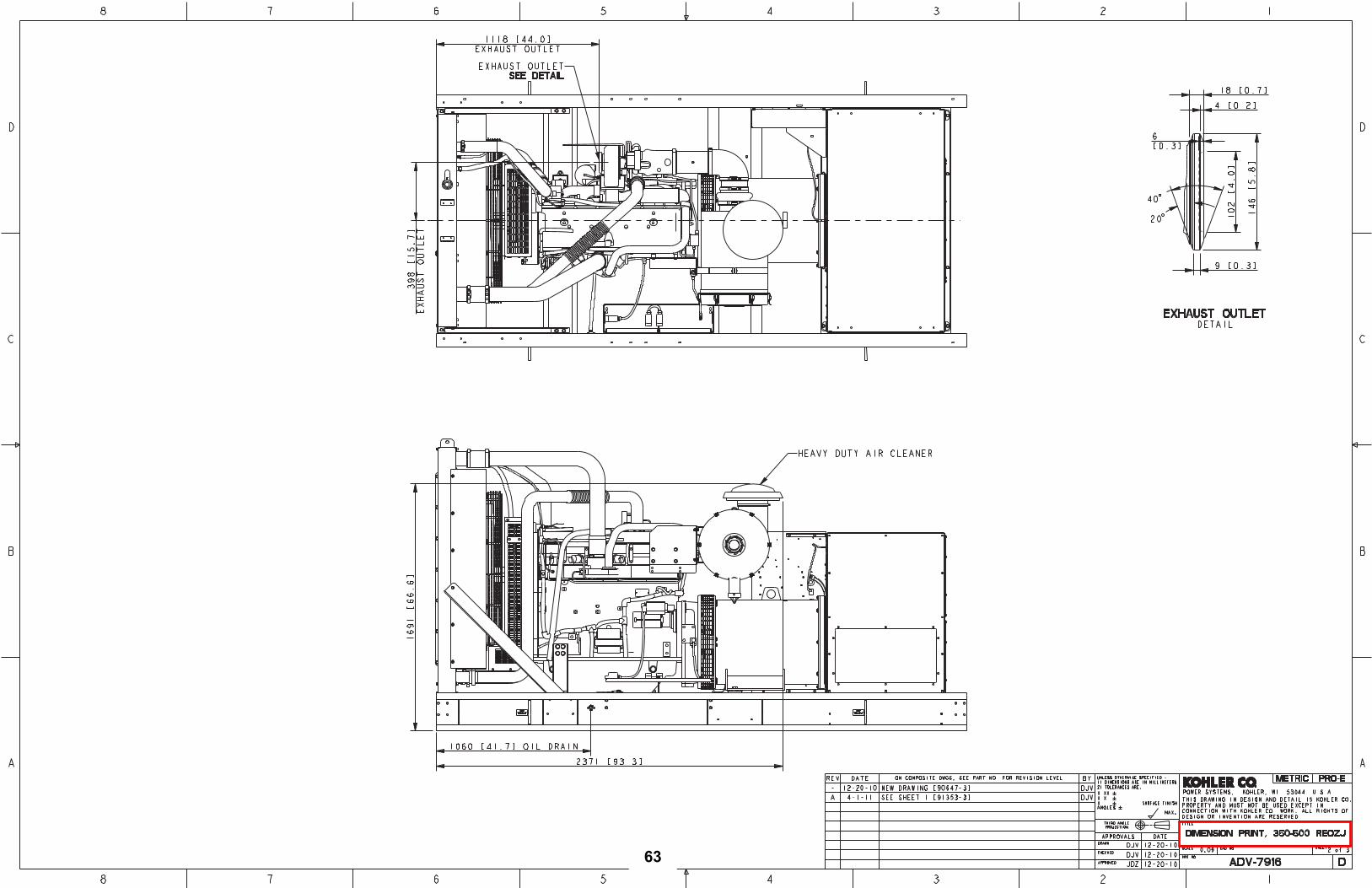
63

64

65

66

67

68

Wiring Schematics
69

70

71
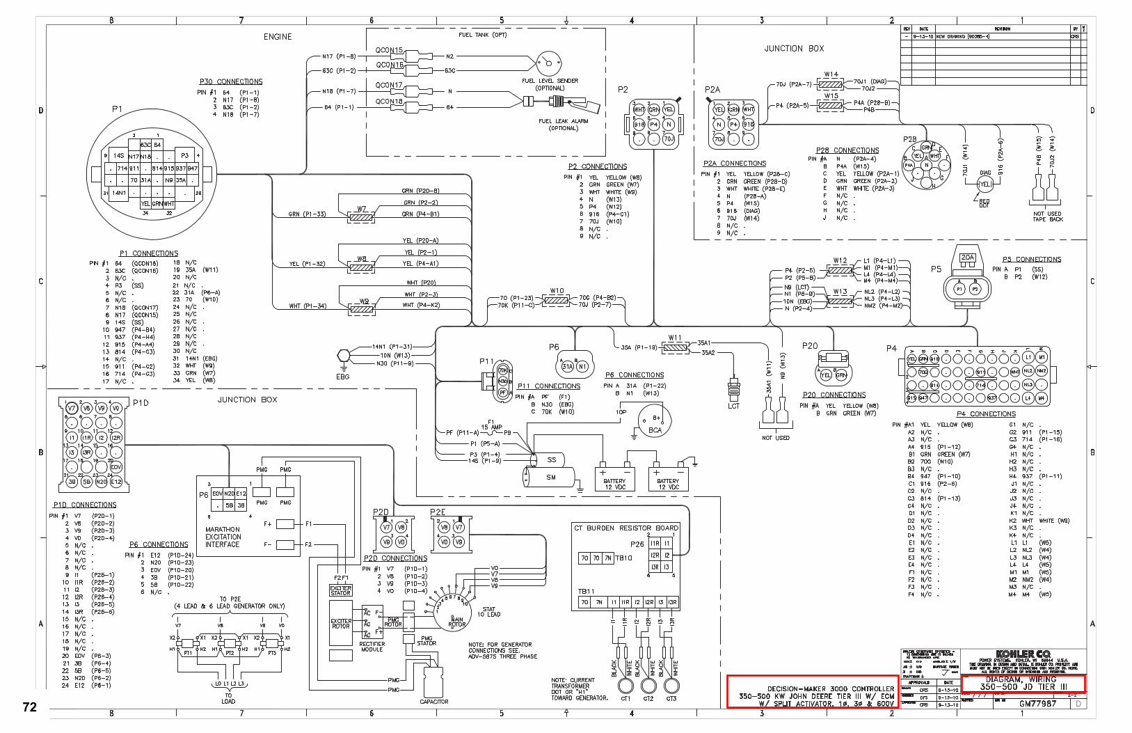
72

73

74

75

76

Miscellaneous
77

78

79

80

81

82

83
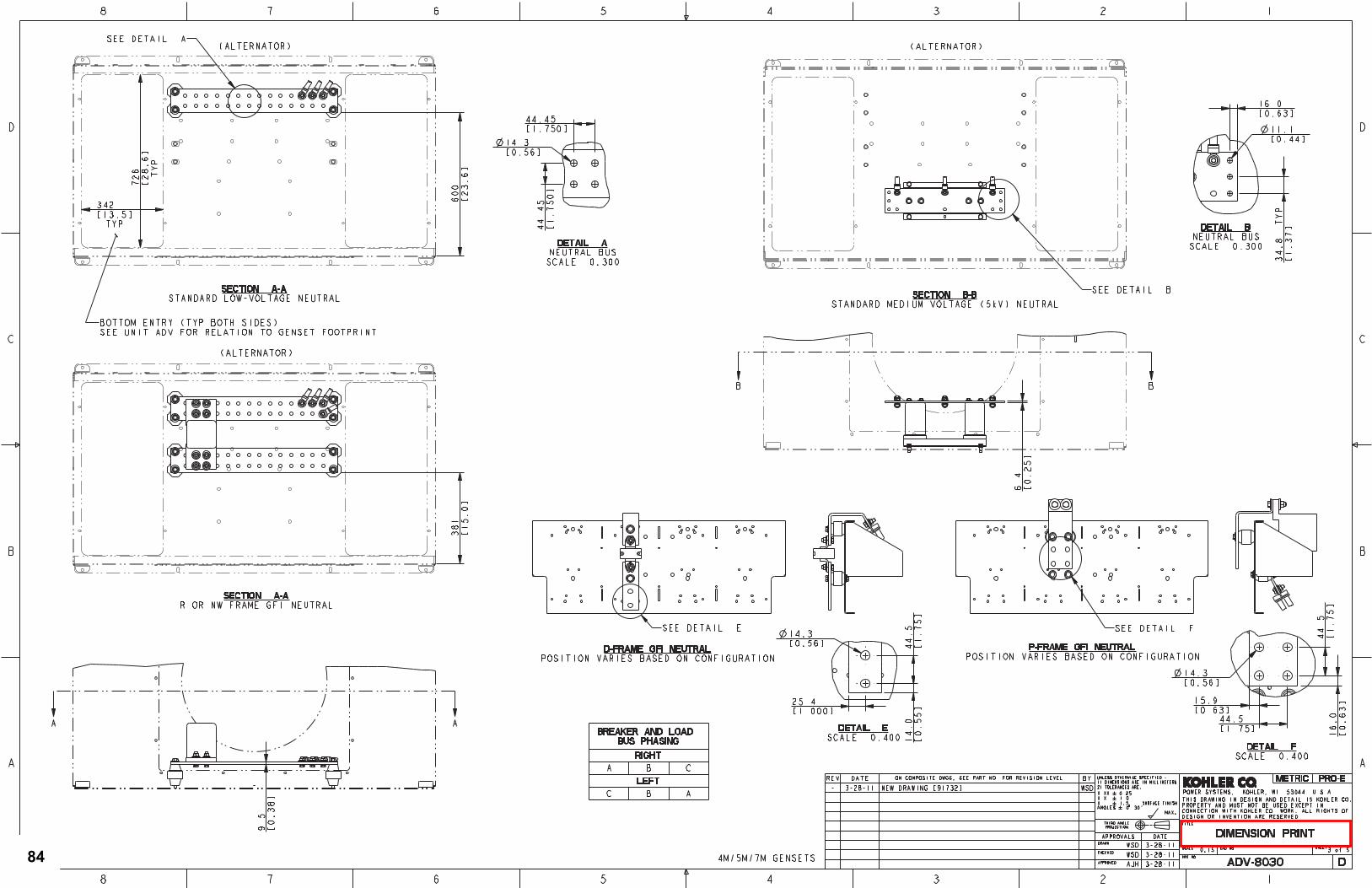
84

85

86

Warranty
87

A Startup Notification form must be on file at Kohler Co. A Startup Notification form must be completed by Seller and received atKohler Co. within 60 days after the date of initial startup. Standby systems not registered within 60 days of startupwill automatically beregistered by Kohler Co. using the Kohler Co. ship date as the startup date.
To obtain warranty service, call 1-800-544-2444 for your nearest authorized Kohler service representative, or write Kohler Co.,Generator Service Department, Kohler, WI 53044 USA.
KOHLERCO.SHALLNOTBELIABLEFORSPECIAL, INCIDENTAL,ORCONSEQUENTIALDAMAGESOFANYKIND including,butnot limited to, incidental consequential laborcosts, installationcharges, telephonecharges,or transportationcharges inconnectionwiththe replacement or repair of defective parts.
This is our exclusive written warranty. We make no other express warranty, nor is anyone authorized to make any in our behalf.
ANY IMPLIED OR STATUTORY WARRANTY, INCLUDING ANY WARRANTY OF MERCHANTABILITY OR FITNESS OFPURCHASE, is expressly limited to the duration of this warranty.
Some states do not allow limitations on how long an implied warranty lasts, or the exclusion or limitation of incidental or consequentialdamages, so the above limitation or exclusion may not apply to you.
This warranty gives you specific legal rights, and you may also have other rights which vary from state to state.
TP-5561 12/99c
Extended Five-Year or Three Thousand (3000)-HourComprehensive Stationary Standby Limited WarrantyThis Kohler Standby Generator System has been manufactured and inspected with care by experienced craftsmen. If you are theoriginal purchaser, Kohler Co.warrants for five years or three thousand (3000) hours,whichever occurs first, that the systemwill be freefrom defects in material and workmanship if properly installed, maintained, and operated in accordance with Kohler Co.’s instructionmanuals. A Kohler distributor, dealer, or authorized representative must perform startup.
This warranty is not effective unless a proper extended warranty registration form and warranty fee have been sent to
Kohler Co. within one year of supervised startup.
During thewarranty period, repair or replacement atKohler Co.’s optionwill be furnished freeof charge for parts, provided an inspectionto Kohler Co.’s satisfaction discloses a defect in material and workmanship, and provided that the part or parts are returned toKohler Co. or anauthorizedservicestation, if requested. This extendedwarrantyexpires five full yearsafter dateof startupor after3000hours of operation, whichever occurs first.
This warranty does not apply to malfunctions caused by damage, unreasonable use, misuse, or normal wear and tear while in yourpossession.
The following will not be covered by this warranty:
1. Normal engine wear, routine tuneups, tuneup parts,adjustments, and periodic service.
2. Damage caused by accidents, improper installation orhandling, faulty repairs not performed by an authorizedservice representative, or improper storage.
3. Damage caused by operation with improper fuel or atspeeds, loads, conditions, modifications, or installationcontrary topublishedspecificationsor recommendations.
4. Damage caused by negligent maintenance such as:
a. Failure to provide the specified type and sufficientlubricating oil.
b. Failure to keep the air intake and cooling fin areasclean.
c. Failure to service the air cleaner.d. Failure to provide sufficient coolant and/or cooling air.e. Failure to perform scheduled maintenance as
prescribed in supplied manuals.f. Failure to exercise with load regularly.
5. Original installation charges and startup costs.
6. Starting batteries and the following related expenses:
a. Labor charges related to battery service.b. Travel expense related to battery service.
7. Engine coolant heaters, heater controls, and circulatingpumps after the first year.
8. Rental of equipment during performance of warrantyrepairs.
9. Non-Kohler-authorized repair shop labor without priorapproval from the Kohler Co. Warranty Department.
10. Parts purchased from sources other than Kohler.Replacement of a failedKohler part with a non-Kohler partvoids warranty on that part.
11. Radiators replaced rather than repaired.
12. Fuel injection pumpsnot repaired locally by an authorizedservicing dealer.
13. Engine fluids such as fuel, oil, or coolant/antifreeze.
14. Shop supplies such as adhesives, cleaning solvents, andrags.
15. Expenses incurred investigating performancecomplaintsunless the problem is caused by defective Kohlermaterials or workmanship.
16. Maintenance items such as fuses, filters, spark plugs,loose/leaking clamps, and adjustments.
KOHLER CO. Kohler, Wisconsin 53044Phone 920-565-3381, Fax 920-459-1646For the nearest sales/service outlet in theUS and Canada, phone 1-800-544-2444KohlerPowerSystems.com
88

Extended Five-Year ComprehensiveTransfer Switch Limited Warranty
This Kohler product has been manufactured and inspected with care by experienced craftsmen. If you are the original purchaser,Kohler Co.warrants for five years that thesystemwill be free fromdefects inmaterial andworkmanship if properly installed,maintained,andoperated inaccordancewithKohler Co. instructionmanuals. AKohlerdistributor, dealer,orauthorizedrepresentativemustperformstartup.
This warranty is not effective unless a proper extended warranty registration form and warranty fee have been sent to
Kohler Co. within one year of supervised startup.
During thewarranty period, repair or replacement atKohler Co.’s optionwill be furnished freeof charge for parts, provided an inspectionto Kohler Co.’s satisfaction discloses a defect in material and workmanship, and provided that the part or parts are returned toKohler Co. or an authorized service station, if requested. This extended warranty expires five full years after date of startup.
This warranty does not apply to malfunctions caused by damage, unreasonable use, misuse, or normal wear and tear while in yourpossession.
A Startup Notification form must be on file at Kohler Co. A Startup Notification form must be completed by Seller and received atKohler Co.within 60 days after the date of initial startup. Product not registeredwithin 60days of startupwill automatically be registeredby Kohler Co. using the Kohler Co. ship date as the startup date.
To obtain warranty service, call 1-800-544-2444 for your nearest authorized Kohler service representative or write Kohler Co.,Generator Service Department, Kohler, WI 53044 USA.
KOHLERCO.SHALLNOTBELIABLEFORSPECIAL, INCIDENTAL,ORCONSEQUENTIALDAMAGESOFANYKIND including,butnot limited to, incidental consequential laborcosts, installationcharges, telephonecharges,or transportationcharges inconnectionwiththe replacement or repair of defective parts.
This is our exclusive written warranty. We make no other express warranty, nor is anyone authorized to make any on our behalf.
ANY IMPLIEDORSTATUTORYWARRANTY, INCLUDINGANYWARRANTYOFMERCHANTABILITYORFITNESSOFPURPOSE,is expressly limited to the duration of this warranty. Some states do not allow limitations on how long an implied warranty lasts, or theexclusion or limitation of incidental or consequential damages, so the above limitation or exclusion may not apply to you.
This warranty gives you specific legal rights, and you may also have other rights that vary from state to state.
The following will not be covered by the warranty:
1. Normal wear, periodic service, and routine adjustments.
2. Damage caused by accidents, improper installation orhandling, faulty repairs not performed by an authorizedservice representative, or improper storage.
3. Damage caused by operation above or below ratedcapacity, voltage, or frequency; modifications; orinstallation contrary to published specifications, codes,recommendations, and accepted industry practices.
4. Original installation charges and startup costs.
5. Damage caused by negligent maintenance such as:
a. Failure to provide a clean, dry environment.b. Failure to perform recommended exercising.c. Failure to perform scheduled maintenance as
prescribed in supplied manuals.d. Useof other than factory-suppliedor -approved repair
parts and/or procedures.
6. Rental of equipment during performance of warrantyrepairs.
7. Non-Kohler-authorized repair shop labor without priorapproval from the Kohler Co. Warranty Department.
8. Expenses incurred investigating performancecomplaintsunless the problem is caused by defective Kohlermaterials or workmanship.
9. Maintenance items such as fuses, lamps, andadjustments.
10. Transfer switch main contacts.
TP-6087 2/00b
KOHLER CO. Kohler, Wisconsin 53044Phone 920-565-3381, Fax 920-459-1646For the nearest sales/service outlet in theUS and Canada, phone 1-800-544-2444KohlerPowerSystems.com
89

90

Certification
91

92

93

G18-56 12/05a
Kohler Standby/Prime Generator Set Test Program
Testing is an integral part of quality assurance. In keepingwith ouruncompromising commitment to quality, safety,
and reliability, every Kohler Standby/Prime power generator set undergoes an extensive series of prototype and
production testing.
Prototype Testing
Prototype testing includes the potentially destructive
tests necessary to verify design, proper function of
protective devices and safety features, and reliability
expectations. Kohler’s prototype testing includes the
following:
� Alternator temperature rise test per NEMA
MG1-32.6. Standby and prime ratings of the
alternator are established during this test.
� Maximum power test to assure that the prime
mover and alternator have sufficient capacity to
operate within specifications.
� Alternator overload test per NEMA MG1-32.8.
� Steady-state load test to ensure voltage regulation
meets or exceeds ANSI C84.1, NEMAMG1-32.17
requirementsand toverifycompliancewithsteady-
state speed control specifications.
� Transient test to verify speed controls meets or
exceeds specifications.
� Transient load tests per NEMA MG1-32.18, and
ISO 8528 to verify specifications of transient
voltage regulation, voltage dip, voltage overshoot,
recovery voltage, and recovery time.
� Motor starting tests per NEMA MG1-32.18.5 to
evaluate capabilities of generator, exciter, and
regulator system.
� Three-phase symmetrical short-circuit test per
NEMA MG1-32.13 to demonstrate short circuit
performance, mechanical integrity, ability to
sustain short-circuit current.
� Harmonic analysis, voltage waveform deviation
per NEMA MG1-32.10 to confirm that the
generator set is producing clean voltage within
acceptable limits.
� Generator set cooling and air flow tests to verify
maximum operating ambient temperature.
� Reliability tests to demonstrate product durability,
followed by root cause analysis of discovered
failures and defects. Corrective action is taken to
improve thedesign,workmanship, or components.
� Acoustical noise intensity and sound attenuation
effects tests.
Production Testing
In production, Kohler Standby/Prime generator sets
are built to the stringent standards established by the
prototype program. Every Kohler Generator set is
fully tested prior to leaving the factory. Production
testing includes the following:
� Stator and exciterwinding high-potential test onall
generators. Surge transient tests on stators for
generators 180 kW or larger. Continuity and
balance tests on all rotors.
� One-step, full-load pickup tests to verify that the
performance of each generator set, regulator, and
governor meets published specifications.
� Regulation and stability of voltage and frequency
are testedandverifiedatno load, 1/4 load, 1/2 load,
3/4 load, and full-rated load.
� Voltage, amperage, frequency and power output
ratings verified by full-load test.
� The proper operation of controller logic circuitry,
prealarm warnings, and shutdown functions is
tested and verified.
� Any defect or variation from specification
discoveredduring testing is correctedand retested
prior to approval for shipment to the customer.
Torsional analysis data, to verify torsional effects are not detrimental and that the generator set will provide
dependable service as specified, is available upon request.
Kohler offers other testing at the customer’s request at an additional charge. These optional tests include power
factor testing, customized load testing for specific application, witness testing, and a broad range of
MIL-STD-705c testing. A certified test report is also available at an additional charge.
KOHLER CO. Kohler, Wisconsin 53044
Phone 920-565-3381, Fax 920-459-1646
For the nearest sales/service outlet in the
US and Canada, phone 1-800-544-2444
KohlerPowerSystemscom
94

Prestartup Checklist
95

96

Columbus, Ohio Cincinnati, Ohio Cleveland, Ohio Indianapolis, Indiana 6850 Commerce Court Drive 7782 Service Center Drive 8465 Tower Drive 1229 Indy Place P.O. Box 489 West Chester, Ohio 45069 P.O. Box 394 Indianapolis, Indiana 46214 Blacklick, Ohio 43004-0489 Telephone (800) 368-7422 Twinsburg, Ohio 44087-0394 Telephone (800) 632-0339 Telephone (800) 523-3587 Telephone (800) 966-2825 __________________________________________________________________________________________________________________________________________
Pre Start-Up Checklist
Attn: ___________________________ Fax/email: ____________________ Company: ______________________ Project: _____________________
Included with your generator package is a complete start-up service. Before this service can be scheduled the following checklist must be completed, signed and returned to the service department for the appropriate branch listed above.
Check
1. _____Generator must be bolted to the concrete pad which has been engineered to meet code.
2._____Exhaust System Indoor units must have the exhaust completely installed. The flexible connector must not be used as an offset of 90 degree. An engineered thimble MUST be used were the exhaust penetrates the roof or wall. At the termination there must a rain cap on vertical discharge and on horizontal discharge there must be either a rain cap or the pipe cut off at a 45 degree with bird screen installed.
Outdoor units require the exhaust to be completely installed including the rain cap which must be able to open and close freely. Rain caps may be secured for shipping.
3. _____ Load Conductors Generator load conductors must be connected to the generator output breaker and the transfer switch. If different size lugs are needed contact your sales representative and note they may take 3 weeks to deliver. Generators generally have the neutral bonded to ground from the factory. If the system requires a solid neutral then the jumper on the generator must be removed. It is usually from the ground stud on the main alternator to the neutral bar.
4. _____ Control Wiring Control wiring should be in a conduit separate from the load conductors. Start wires need to be a minimum of number 18 and labeled #3. They need to be pulled up into the generator controller and to the connection point in the transfer switch. The service technician can land these. If start wires are in the same conduit as the load conductors they should be shielded.
5. _____ Remote Annunciator Remote annunciator panel requires 2 number 14awg minimum from the generator to the annunciator. A Belden 9841 cable is also required. 3 number 14’s are required from
97

the transfer switch to the annunciator. If using with a building network contact the service department for proper installation requirements.
6. _____ Utility Power Utility power must be connected and available to the transfer switch. Don’t plug thecontroller in! Building loads must be available. Transfer switch must be allowed to be tested. Transfer Switch must be powered down to plug in controller. Power outages will occur during testing.
7. _____ Radiator Ductwork Cooling system duct at radiator must be installed. Intake and exhaust louvers must be operational.
8. _____ Diesel Fuel System Fuel tank must have pressure test completed before scheduling start up. The tank should be at least 75% full with #2 off highway diesel supreme.
9. _____ Spark Ignited Engines Fuel system must be installed per the Kohler installation manual, TP-5700, pages 21-24 and 32. Gas pressure MUST be 4-6 oz or 7-11 inches of water column at the generator fuel inlet at all times. Supply volume must be sized for 100% rated load. Volume requirement is supplied on the generator data sheet.
10. ____ Block Heater Block heater must be wired for the appropriate voltage. Do Not Energize!
11. ____ Battery Charger Battery charger must be installed and wired. Check installation instructions. If charger is more than 15 feet from batteries, additional sensing wires may be required. If this is a NFPA 110 installation 3 additional wires must be pulled from the charger to the generator controller for alarms.
Start-up dates are reserved on a first come first serve basis and require at least 1-2 week notice.
Starts up are to be performed during normal business hours and generally can be completed in 1-2 business days. If after hours testing is required there will be additional charges.
If there is anything on this list that is marked as being ready and it is not, requiring a second trip, the contractor will be held responsible for the additional trip charges.
__________________________________ __________________________ ________ Name (print) Signature Date
98