shop online at - omega engineering · shop online at omega.com® user’s ... adjusted manually...
TRANSCRIPT

OS212 SERIESIR Temperature Sensors
®
e-mail: [email protected] latest product manuals:
omegamanual.info
Shop online atomega.com ®
User’s Guide®
MADE IN UNITED KINGDOM

Servicing North America:U.S.A.: One Omega Drive, Box 4047ISO 9001 Certified Stamford CT 06907-0047
Tel: (203) 359-1660FAX: (203) 359-7700e-mail: [email protected]
Canada: 976 BergarLaval (Quebec) H7L 5A1, CanadaTel: (514) 856-6928FAX: (514) 856-6886e-mail: [email protected]
For immediate technical or application assistance:
U.S.A. and Canada: Sales Service: 1-800-826-6342/1-800-TC-OMEGA®
Customer Service: 1-800-622-2378/1-800-622-BEST®
Engineering Service: 1-800-872-9436/1-800-USA-WHEN®
Mexico: En Espanol: (001) 203-359-7803FAX: (001) 203-359-7807e-mail: [email protected]@omega.com.mx
Servicing Europe:Benelux: Managed by the United Kingdom Office
Toll-Free: 0800 099 3344 TEL: +31 20 347 21 21FAX: +31 20 643 46 43 e-mail: [email protected]
Czech Republic: Frystatska 184, 733 01 Karvina , Czech RepublicTel: +420 (0)59 6311899FAX: +420 (0)59 6311114Toll Free: 0800-1-66342e-mail: [email protected]
Germany/Austria: Daimlerstrasse 26, D-75392 Deckenpfronn, GermanyTel: +49 (0)7056 9398-0FAX: +49 (0)7056 9398-29Toll Free in Germany: 0800 639 7678e-mail: [email protected]
United Kingdom: One Omega Drive, River Bend Technology CentreISO 9002 Certified Northbank, Irlam, Manchester
M44 5BD United Kingdom Tel: +44 (0)161 777 6611FAX: +44 (0)161 777 6622Toll Free in United Kingdom: 0800-488-488e-mail: [email protected]
OMEGAnet® Online Service Internet e-mailomega.com [email protected]
It is the policy of OMEGA Engineering, Inc.to comply with all worldwide safety and EMC/EMIregulations that apply. OMEGA is constantly pursuing certification of its products to the EuropeanNew Approach Directives. OMEGA will add the CE mark to every appropriate device uponcertification.The information contained in this document is believed to be correct, but OMEGA accepts no liability for anyerrors it contains, and reserves the right to alter specifications without notice.WARNING: These products are not designed for use in, and should not be used for, human applications.
®

3
›OS212 Series non-contact infrared sensors measure temperatures from -20°C to 500°C and pro-vide a linear 4 to 20mA output. This output signal is compatible with almost any indicator, control-ler, recorder, data logger etc., without the need for special interfacing or signal conditioning.
The sensor’s emissivity setting can be adjusted from 0.2 to 1.0 to cope with different target mate-rials and is controlled by a 4-20 mA input. This gives the opportunity to adjust the emissivity setting automatically from a programmable logic controller (PLC). Alternatively the emissivity setting can be adjusted manually using the optional OS210-PT module. If the 4-20 mA input is left open or short-circuit the emissivity setting defaults to 0.95.
OS212 SerieS SpecificatiOnS
temperature range vs field-of-View tablefield of View -20ºc to 100ºc 0ºc to 250ºc 0ºc to 500ºc
2:1 OS212-LT OS212-MT -15:1 OS152-LT OS152-MT OS152-HT30:1 OS302-LT OS302-MT OS302-HTø5mm @ 100mm OS802-LT OS802-MT OS802-HT
Output 4-20 mAAccuracy ±1% of reading or ±1ºC whichever is greaterRepeatability ± 0.5% of reading or ± 0.5ºC whichever is greaterEmissivity 0.2 to 1.0 via 4-20 mA inputResponse Time, t90 240 ms (90% response)Spectral Range 8 to 14 μmSupply Voltage 24 V DC (28 V DC max.)Min. Sensor Voltage 6 V DCMax. Loop Impedance 900 Ω ( 4-20 mA output)Input Impedance 50 Ω MechanicalConstruction Stainless SteelDimensions 18 mm diameter x 103 mm longThread Mounting M16 x 1 mm pitchCable Length 1 mWeight with Cable 95 genvironMentalEnvironmental Rating IP65Ambient Temperature Range 0ºC to 70ºCRelative Humidity 95% max. non-condensing
OS210-pt SpecificatiOnSOutput 4-20 mASupply Voltage 24 V DC (13 V to 28 V DC)Display Format 3.5 digit LCDDisplay Units Emissivity (0.2 to 1.0) or current (4 - 20 mA)Adjustment Push-buttons (raise/lower/set)MechanicalConstruction Polycarbonate with gasket, transparent lid (PC) and quick release screwsMounting SurfaceDimensions 65 mm tall x 50 mm wide x 35 mm deepWeight 72 genvironMentalEnvironmental Rating IP65Ambient Temperature Range 0ºC to 70ºCRelative Humidity 95% max. non-condensing
engl
ish
4 ›
InstallatIonThe installation process consists of the following stages: Preparation Mechanical installation Electrical installation
Please read the following sections thoroughly before proceeding with the installation.
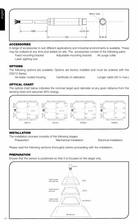
preparatIonEnsure that the sensor is positioned so that it is focused on the target only.
accessorIesA range of accessories to suit different applications and industrial environments is available. These may be ordered at any time and added on-site. The accessories consist of the following parts. Fixed mounting bracket Adjustable mounting bracket Air purge collar Laser sighting tool
optIonsThe following options are available. Options are factory installed and must be ordered with the OS212 Series. Air/water cooled housing Certificate of calibration Longer cable (30 m max.)
optIcal cHartThe optical chart below indicates the nominal target spot diameter at any given distance from the sensing head and assumes 90% energy.
1000
103
12
18
M16 x 1mm
Distance: Sensor to object (inches)
Distance: Sensor to object (mm)
11.945.2
78.6
0.51.8
3.1
0 19.7 39.4
0
11.9
0 500 1000
Spo
t Dia
.(in
ches
) S
pot D
ia.
(mm
)
Spo
t Dia
.(in
ches
) S
pot D
ia.
(mm
)
Distance: Sensor to object (inches)
Distance: Sensor to object (mm)
Spo
t Dia
.(in
ches
) S
pot D
ia.
(mm
) Distance: Sensor to object (inches)
Distance: Sensor to object (mm)
11.9
0.5
61.9111.9
0.52.4
4.40 4 8
0
0
5.0
0.20
100
3.9
12.5
0.49
200
7.9
100 200
D:S 15:1D:S 2:1
Distance: Sensor to object (inches)
Distance: Sensor to object (mm)
11.928.6 45.2
0.51.1 1.8
0 19.7 39.4
0 500 1000
Spo
t Dia
.(in
ches
) S
pot D
ia.
(mm
)
D:S 30:1
Sensor
BEST
GOOD
INCORRECT
Background
Target greater than spot size
Target equal tospot size
Target smallerthan spot size
OS212 OS152 OS302 OS802
engl
ish

5
›Distance anD spot sizeThe size of the area (spot size) to be measured determines the distance between the sensor and the target. The spot size must not be larger than the target. The sensor should be mounted so that the measured spot size is smaller than the target.
aMbient teMperatureThe sensor is designed to operate in ambient temperatures from 0°C to 70°C. For ambient tem-peratures above 70°C, an air/water-cooled housing will be required.
Avoid thermal shock. Allow 20 minutes for the unit to adjust to large changes in ambient tem-perature.
atMospheric QualitySmoke, fumes or dust can contaminate the lens and cause errors in temperature measurement. In these types of environment the air purge collar should be used to help keep the lens clean.
electrical interference To minimise electromagnetic interference or ‘noise’, the sensor should be mounted away from motors, generators and such like.
WiringCheck the distance between the sensor and the indicating/controlling device. If necessary, the OS212 Series sensor can be ordered with a longer cable attached.
poWer supplyBe sure to use a 24 V DC (25 mA) power supply.
mecHanIcal InstallatIonAll sensors come with a 1m cable and a mounting nut. The sensor can be mounted on brackets or cut outs of your own design, or you can use the fixed and adjustable mounting bracket acces-sories which are shown below. Note: the sensor should be grounded at one point, either the cable shield termination or the sensor housing, but not both.
12.0
45.0
50.0 50.0
40.0
9.0
15.0
25.0 25.0
60° Rotation 60° Rotation
60° Rotation
9.0
48.0
Fixed Bracket Adjustable Bracket
2 x Mounting Holes M4 Clearance 2 x Mounting Holes M4 Clearance
9.0
24.024.0
Ø16.0
engl
ish

6 ›
air/Water cooleD housingThe air/water cooled housing shown below allows the sensor to withstand high ambient temperatures. It is equipped with two 1/8” BSP fittings. Water temperature should be 10°C to 27°C for efficient cool-ing. Chilled water below 10°C is not recommended. To avoid condensation, the air purge collar should be used with the water-cooled housing. Water flow rate should not be more than 0.5 to 1.5 litres/min.
40.0
2119 63
103
M16 x 1mm1/8 BSP water/air connections
1/8 BSP Air connection
25OS210-APSW
(OS212)
50OS210-APSN
(OS152, OS302 & OS802)
20
29
40
air purge collarThe air purge collar below is used to keep dust, fumes, moisture, and other contaminants away from the lens. It must be screwed in fully. Air flows into the 1/8” BSP fitting and out of the front aperture. Air flow should be no more than 5 to 15 litres/min.
Clean or ‘instrument’ air is recommended.
engl
ish
7
›electrIcal InstallatIon
+ - -
+
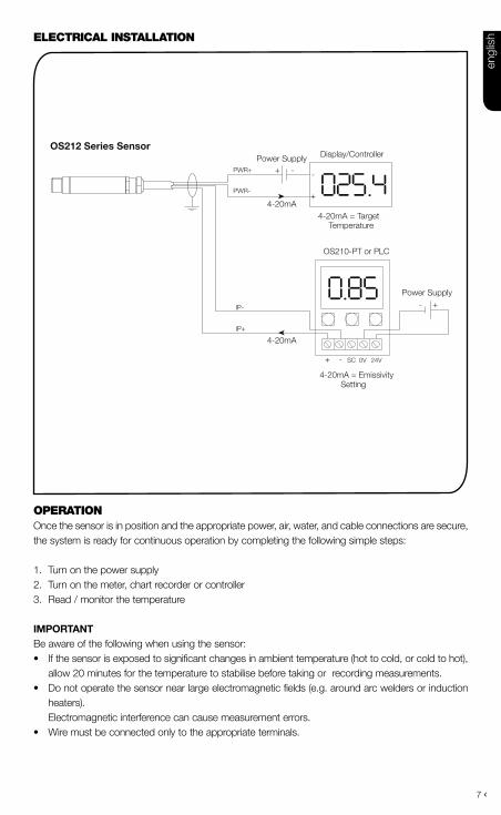
4-20mA = TargetTemperature
Power Supply
- SC 0V 24V
-
+
+
4-20mA = EmissivitySetting
Power Supply
OS212 Series Sensor
IP-
IP+
PWR+
PWR-
Display/Controller
OS210-PT or PLC
4-20mA
4-20mA
operatIonOnce the sensor is in position and the appropriate power, air, water, and cable connections are secure, the system is ready for continuous operation by completing the following simple steps:
1. Turn on the power supply2. Turn on the meter, chart recorder or controller3. Read / monitor the temperature
iMpOrtantBe aware of the following when using the sensor:• If the sensor is exposed to significant changes in ambient temperature (hot to cold, or cold to hot),
allow 20 minutes for the temperature to stabilise before taking or recording measurements.• Do not operate the sensor near large electromagnetic fields (e.g. around arc welders or induction
heaters). Electromagnetic interference can cause measurement errors.• Wire must be connected only to the appropriate terminals.
engl
ish

8 ›
Maintenance Our customer service representatives are available for application assistance, calibration, repair, and solutions to specific problems. Contact our Service Department before returning any equipment. In many cases, problems can be solved over the telephone. If the sensor is not performing as it should, try to match the symptom below to the problem. If the table does not help, call Omega for further advice.
troubleshooting
Symptom probable cause Solution
No output No power to sensor Check power supply
Erroneous temperature Incorrect wire connection Check wire colour codes
Erroneous temperature Faulty sensor cable Verify cable continuity
Erroneous temperature Field of view obstruction Remove obstruction
LenS cLeaningKeep the lens clean at all times. Any foreign matter on the lens would affect measurement accuracy. Blow off loose particles (if not using the air purge accessory) with an air ‘puffer’.
engl
ish

9
›Les détecteurs infra-rouge sans contact OS212 Series mesurent des températures entre -20°C et 500°C, et fournissent une sortie linéaire de 4 jusqu’à 20mA. Ce signal de sortie est compatible avec pratiquement tous les indicateurs, régulateurs, enregistreurs, enregistreurs de données, etc., et n’exige aucune interface spécifique ni prétraitement de signaux spécial.
L’émissivité du détecteur peut être réglée entre 0,2 et 1,0 afin de prendre en compte des matériaux cibles différents, et elle est commandée par une entrée 4-20 mA. Ce dispositif offre la possibilité de régler l’émissivité automatiquement à partir d’un automate programmable (PLC). L’émissivité peut également être réglée de façon manuelle à l’aide du module OS210-PT en option. Si l’entrée 4-20 mA est laissée ouverte, ou s’il y a un court-circuit, l’émissivité se règle par défaut sur 0,95.
SpécificatiOnS - OS212 SerieS
tableau montrant la gamme de températures vs le champ de vision champ de Visée -20ºc à 100ºc 0ºc à 250ºc 0ºc à 500ºc
2:1 OS212-LT OS212-MT -15:1 OS152-LT OS152-MT OS152-HT30:1 OS302-LT OS302-MT OS302-HTø5mm @ 100mm OS802-LT OS802-MT OS802-HT
Sortie 4 à 20mAPrécision ± 1% de la mesure ou ± 1°C, celui qui est le plus importantFidélité ± 0,5% de la mesure ou ± 0,5°C, celui qui est le plus importantEmissivité 0,2 à 1,0Temps de réponse 240ms (réponse 90%)Réponse spectrale 8 à 14μmVoltage d’alimentation 24V cc (max. 28V cc)Voltage du détecteur Min. 6V ccImpédance en boucle maximale 900 Ohms (4-20mA sortie)Impédance d’entrée 50 Ω MécaniQuesConstruction Acier inoxydableDimensions 18mm diamètre x 103mmLongueur du câble 1mPoids avec câble 95genvironneMentalesCatégorie environnementale IP65Echelle de température ambiante 0°C à 70°C Humidité relative Maximum 95% non condensée
SpécificatiOnS - OS210-ptSortie 4 à 20mAVoltage d’alimentation 24 V cc (13V à 28V cc)Format d’affichage LCD, 3,5 chiffresUnités d’affichage Emissivité (0,2 à 1,0) ou courant (4 - 20 mA)Réglage Boutons poussoirs (augmenter / réduire / fixer)MécaniQuesConstruction Polycarbonate avec joint statique, couvercle transparent (PC) et vis à déserrage rapideSupport SurfaceDimensions 65 mm x 50 mm x 35 mmPoids 72 genvironMentalCatégorie environnementale IP65Echelle de température ambiante 0°C à 70°C Humidité relative Maximum 95% non condensée
franç
ais

10 ›
Détecteur
LE MEILLEUR
BON
PAS BON
Fond
Cible plus grand que la grandeur du point
Cible même grandeur que le point
Cible plus petit que la grandeur du point
InstallatIonLe processus d’installation consiste aux étapes suivantes : Préparation Installation mécanique Installation électriqueIl faut lire les sections suivantes attentivement avant de commencer l’installation.
préparatIonS’assurer que le détecteur est mis en place pour qu’il ne se concentre que sur la cible.
accessoIresUne gamme d’accessoires pour convenir aux différentes applications et environnements industriels est disponible. Les accessoires peuvent être commandés à tout moment et ajoutés sur place. Ils consistent en : Un support de fixation fixe Un support de fixation réglable Un collier de purge d’air Outil de visée Laser
optIonsLes options suivantes sont disponibles : Les options sont installées en usine et doivent être com-mandées avec le détecteur OS212 Series. Boîtier refroidi à l’air/eau Certificat de calibrage Câble plus long (30 m max.)
taBleaU optIQUeLe tableau optique ci-dessous indique le diamètre du point cible nominal à n’importe quelle dis-tance de la tête de détection et assume 90% d’énergie.
1000
103
12
18
M16 x 1mm
Distance : Détecteur / objet (inches)
Distance : Détecteur / objet (mm)
11.945.2
78.6
0.51.8
3.1
0 19.7 39.4
0
11.9
0 500 1000
Dia
mèt
re
du p
oint
(in
ches
)
Dia
mèt
re
du p
oint
.(m
m)
Dia
mèt
re
du p
oint
(in
ches
)
Dia
mèt
re
du p
oint
.(m
m)
Distance : Détecteur / objet (inches)
Distance : Détecteur / objet (mm)
Dia
mèt
re
du p
oint
(in
ches
)
Dia
mèt
re
du p
oint
.(m
m)
Distance : Détecteur / objet (inches)
Distance : Détecteur / objet (mm)
11.9
0.5
61.9111.9
0.52.4
4.40 4 8
0
0
5.0
0.20
100
3.9
12.5
0.49
200
7.9
100 200
D:S 15:1D:S 2:1
Distance : Détecteur / objet (inches)
Distance : Détecteur / objet (mm)
11.928.6 45.2
0.51.1 1.8
0 19.7 39.4
0 500 1000
Dia
mèt
re
du p
oint
(in
ches
)
Dia
mèt
re
du p
oint
.(m
m)
D:S 30:1
OS212 OS152 OS302 OS802
franç
ais
11
›Distance et taille Du pointLa taille de la zone (taille du point) qui doit être mesurée détermine la distance entre le détecteur et la cible. La taille du point ne doit pas être plus grande que la cible. Le détecteur devrait être monté de façon à ce que la taille du point mesuré est plus petite que la cible.
teMpérature aMbianteLe détecteur est conçu pour fonctionner en températures ambiantes de 0°C à 70°C. Pour les températures ambiantes supérieures à 70°C, un boîtier refroidi à l’air/eau est nécessaire.
Eviter les chocs thermiques. Allouer 20 minutes au thermomètre, pour qu’il s’adapte à d’importantes fluctuations de température ambiante.
Qualité atMosphériQueLa fumée, les vapeurs ou la poussière peuvent contaminer la lentille et provoquer des erreurs dans la mesure de température. Dans ces genres d’environnement, le collier de purge d’air devrait être utilisé pour aider à garder la lentille propre.
interférence électriQue Pour réduire l’interférence électromagnétique ou ‘bruit’, le détecteur devrait être monté à l’écart de moteurs, générateurs, et autres appareils similaires.
câblageVérifier la distance entre le détecteur et l’appareil d’indication / de contrôle. Si nécessaire, le détecteur OS212 Series peut être commandé avec un câble attaché plus long.
aliMentation électriQueS’assurer qu’une alimentation électrique de 24Vcc (25mA) est utilisée.
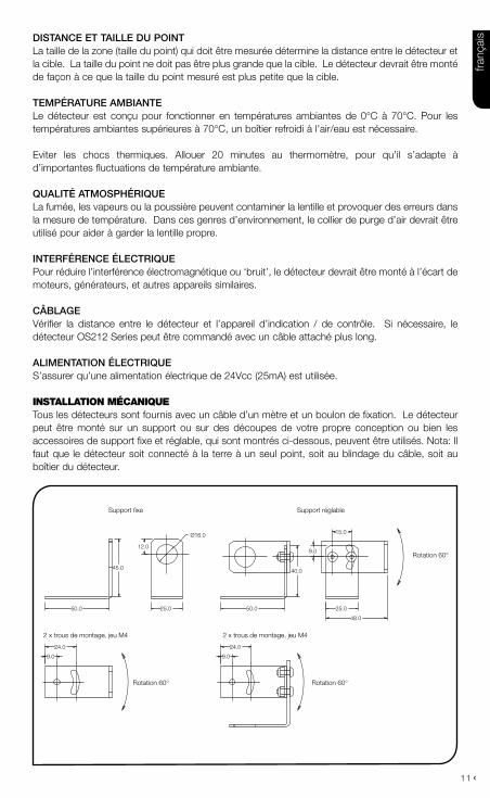
InstallatIon mécanIQUe Tous les détecteurs sont fournis avec un câble d’un mètre et un boulon de fixation. Le détecteur peut être monté sur un support ou sur des découpes de votre propre conception ou bien les accessoires de support fixe et réglable, qui sont montrés ci-dessous, peuvent être utilisés. Nota: Il faut que le détecteur soit connecté à la terre à un seul point, soit au blindage du câble, soit au boîtier du détecteur.
12.0
45.0
50.0 50.0
40.0
9.0
15.0
25.0 25.0
9.0
48.0
9.0
24.024.0
Ø16.0
Rotation 60° Rotation 60°
Rotation 60°
Support fixe Support réglable
2 x trous de montage, jeu M4 2 x trous de montage, jeu M4
franç
ais
12 ›
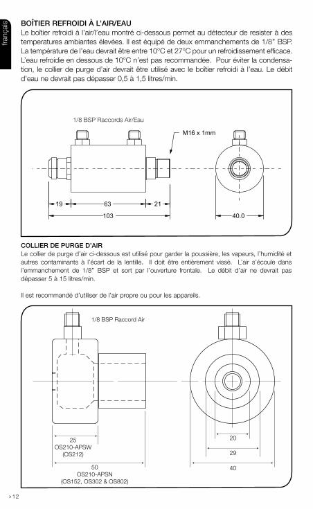
boîtier refroiDi à l’air/eauLe boîtier refroidi à l’air/l’eau montré ci-dessous permet au détecteur de resister à des temperatures ambiantes élevées. Il est équipé de deux emmanchements de 1/8’’ BSP. La température de l’eau devrait être entre 10°C et 27°C pour un refroidissement efficace. L’eau refroidie en dessous de 10°C n’est pas recommandée. Pour éviter la condensa-tion, le collier de purge d’air devrait être utilisé avec le boîtier refroidi à l’eau. Le débit d’eau ne devrait pas dépasser 0,5 à 1,5 litres/min.
collier De purge D’airLe collier de purge d’air ci-dessous est utilisé pour garder la poussière, les vapeurs, l’humidité et autres contaminants à l’écart de la lentille. Il doit être entièrement vissé. L’air s’écoule dans l’emmanchement de 1/8’’ BSP et sort par l’ouverture frontale. Le débit d’air ne devrait pas dépasser 5 à 15 litres/min.
Il est recommandé d’utiliser de l’air propre ou pour les appareils.
40.0
2119 63
103
M16 x 1mm
1/8 BSP Raccords Air/Eau
20
29
40
1/8 BSP Raccord Air
25OS210-APSW
(OS212)
50OS210-APSN
(OS152, OS302 & OS802)
franç
ais

13
›InstallatIon èlectrIQUe
fOnctiOnneMentUne fois que le détecteur est en place et que les connexions appropriées d’alimentation, d’air, d’eau et de câbles sont bien fixées, le système est prêt pour fonctionner en continu en complétant les simples étapes suivantes :
1. Mettre en route l’alimentation électrique2. Mettre en route le compteur, l’enregistreur de tableau ou le contrôleur3. Lire / contrôler la temperature
iMpOrtantIl faut faire attention aux suivants lors de l’utilisation du détecteur :• Si le détecteur est exposé à des changements significatifs de température ambiante (chaud à
froid, ou froid à chaud), avant de prendre ou d’enregistrer des mesures attendre 20 minutes que la température se stabilise.
• Ne pas faire fonctionner le détecteur près d’importants champs électromagnétiques (par exem-ple autour d’un arc de soudage ou d’appareils chauffants à induction). Des interférences électromagnétiques peuvent provoquer des erreurs de mesure.
• Le câble ne doit être relié qu’à des terminaux appropriés.
+ - -
+
4-20mA = Température cible
Alimentationélectrique
Alimentationélectrique
- SC 0V 24V
-
+
+
4-20mA = Emissivité
Détecteur OS212 Series
IP-
IP+
PWR+
PWR-
Afficheur/Contrôleur
OS210-PT/ PLC
4-20mA
4-20mA
franç
ais

14 ›
entretienLes représentants du service clientèle sont disponibles pour aider, calibrer, réparer et résoudre des problèmes particuliers. Contacter le service technique avant de retourner l’équipement. Dans beaucoup de cas, les problèmes peuvent être résolus par téléphone. Si le détecteur ne fonctionne pas comme il le devrait, essayer de faire correspondre le symptôme ci-dessous au problème. Si le tableau n’aide pas, appeler Omega pour plus de renseignement.
Diagnostic de défaillances
Symptôme cause probable Solution
Pas de sortie Pas d’alimentation au détect-eur
Vérifier l’alimentation élec-trique
Température erronée Connexion incorrecte du câble
Vérifier les codes de cou-leurs du câble
Température erronée Câble du détecteur défaillant Vérifier la continuité du câble
Température erronée Obstruction champs de vue Retirer l’obstruction
nettOyage De La LentiLLeGarder la lentille propre à tout moment. Toute matière étrangère sur la lentille affecterait la précision de la mesure. Souffler les particules libres (si l’accessoire de purge d’air n’est pas utilisé) avec un ‘soufflet’.
franç
ais
15
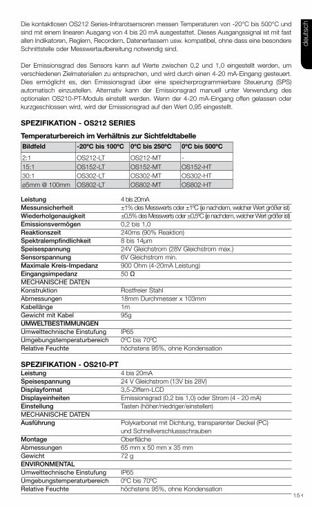
›Die kontaktlosen OS212 Series-Infrarotsensoren messen Temperaturen von -20°C bis 500°C und sind mit einem linearen Ausgang von 4 bis 20 mA ausgestattet. Dieses Ausgangssignal ist mit fast allen Indikatoren, Reglern, Recordern, Datenerfassern usw. kompatibel, ohne dass eine besondere Schnittstelle oder Messwertaufbereitung notwendig sind.
Der Emissionsgrad des Sensors kann auf Werte zwischen 0,2 und 1,0 eingestellt werden, um verschiedenen Zielmaterialien zu entsprechen, und wird durch einen 4-20 mA-Eingang gesteuert. Dies ermöglicht es, den Emissionsgrad über eine speicherprogrammierbare Steuerung (SPS) automatisch einzustellen. Alternativ kann der Emissionsgrad manuell unter Verwendung des optionalen OS210-PT-Moduls einstellt werden. Wenn der 4-20 mA-Eingang offen gelassen oder kurzgeschlossen wird, wird der Emissionsgrad auf den Wert 0,95 eingestellt.
SpezifikatiOn - OS212 SerieS
temperaturbereich im Verhältnis zur SichtfeldtabelleBildfeld -20ºc bis 100ºc 0ºc bis 250ºc 0ºc bis 500ºc
2:1 OS212-LT OS212-MT -15:1 OS152-LT OS152-MT OS152-HT30:1 OS302-LT OS302-MT OS302-HTø5mm @ 100mm OS802-LT OS802-MT OS802-HT
leistung 4 bis 20mAMessunsicherheit ±1% des Messwerts oder ±1ºC (je nachdem, welcher Wert größer ist)Wiederholgenauigkeit ±0,5% des Messwerts oder ±0,5ºC (je nachdem, welcher Wert größer ist)emissionsvermögen 0,2 bis 1,0reaktionszeit 240ms (90% Reaktion)spektralempfindlichkeit 8 bis 14μmspeisespannung 24V Gleichstrom (28V Gleichstrom max.)sensorspannung 6V Gleichstrom min.Maximale Kreis-impedanz 900 Ohm (4-20mA Leistung)eingangsimpedanz 50 Ω MECHAnISCHE DATEnKonstruktion Rostfreier Stahl Abmessungen 18mm Durchmesser x 103mmKabellänge 1mGewicht mit Kabel 95guMWeltbestiMMungenUmwelttechnische Einstufung IP65Umgebungstemperaturbereich 0ºC bis 70ºCRelative Feuchte höchstens 95%, ohne Kondensation
SpezifikatiOn - OS210-ptleistung 4 bis 20mAspeisespannung 24 V Gleichstrom (13V bis 28V)Displayformat 3,5-Ziffern-LCDDisplayeinheiten Emissionsgrad (0,2 bis 1,0) oder Strom (4 - 20 mA)einstellung Tasten (höher/niedriger/einstellen)MECHAnISCHE DATEnausführung Polykarbonat mit Dichtung, transparenter Deckel (PC) und SchnellverschlussschraubenMontage OberflächeAbmessungen 65 mm x 50 mm x 35 mmGewicht 72 genvironMentalUmwelttechnische Einstufung IP65Umgebungstemperaturbereich 0ºC bis 70ºCRelative Feuchte höchstens 95%, ohne Kondensation
deut
sch
16 ›
ZUBeHörEine Reihe von Zubehörteilen für unterschiedliche Anwendungen und industrielle Umgebungen sind erhältlich.Die Zubehörteilen können jederzeit bestellt und vor Ort installiert werden. Die folgenden Zubehörteile sind lieferbar: Feste Halterung Verstellbare Halterung Luftspülmanschette Laserzielstrahl
OptiOnenDie folgenden Optionen sind verfügbar. Die Optionen werden werksmäßig installiert und müssen zusammen mit dem OS212 Series-Sensor bestellt werden. Luft-/wassergekühltes Gehäuse Eichbescheinigung Längeres Kabel (max. 30 m)
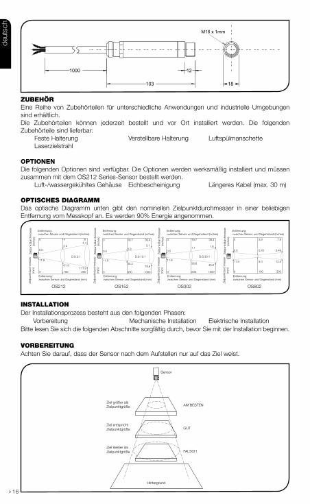
optIscHes DIaGrammDas optische Diagramm unten gibt den nominellen Zielpunktdurchmesser in einer beliebigen Entfernung vom Messkopf an. Es werden 90% Energie angenommen.
InstallatIonDer Installationsprozess besteht aus den folgenden Phasen: Vorbereitung Mechanische Installation Elektrische InstallationBitte lesen Sie sich die folgenden Abschnitte sorgfältig durch, bevor Sie mit der Installation beginnen.
vorBereItUnGAchten Sie darauf, dass der Sensor nach dem Aufstellen nur auf das Ziel weist.
1000
103
12
18
M16 x 1mm
11.945.2
78.6
0.51.8
3.1
0 19.7 39.4
0
11.9
0 500 1000
Ziel
punk
tdur
chm
esse
r(in
ches
) Zi
elpu
nktd
urch
mes
ser
(mm
)
Entfernung:zwischen Sensor und Gegenstand (inches)
Entfernung:zwischen Sensor und Gegenstand (mm)
Ziel
punk
tdur
chm
esse
r(in
ches
) Zi
elpu
nktd
urch
mes
ser
(mm
)
Entfernung:zwischen Sensor und Gegenstand (inches)
Entfernung:zwischen Sensor und Gegenstand (mm)
Ziel
punk
tdur
chm
esse
r(in
ches
) Zi
elpu
nktd
urch
mes
ser
(mm
)
Entfernung:zwischen Sensor und Gegenstand (inches)
Entfernung:zwischen Sensor und Gegenstand (mm)
Ziel
punk
tdur
chm
esse
r(in
ches
) Zi
elpu
nktd
urch
mes
ser
(mm
) Entfernung:zwischen Sensor und Gegenstand (inches)
Entfernung:zwischen Sensor und Gegenstand (mm)
11.9
0.5
61.9111.9
0.52.4
4.40 4 8
0
0
5.0
0.20
100
3.9
12.5
0.49
200
7.9
100 200
D:S 15:1D:S 2:111.9
28.6 45.2
0.51.1 1.8
0 19.7 39.4
0 500 1000
D:S 30:1
Sensor
AM BESTEN
GUT
FALSCH
Hintergrund
Ziel größer als Zielpunktgröße
Ziel entspricht Zielpunktgröße
Ziel kleiner als Zielpunktgröße
OS212 OS152 OS302 OS802
deut
sch
17
›entfernung unD zielpunKtgrösseDie Größe des Messbereichs (Zielpunktgröße) bestimmt die Entfernung zwischen Sensor und Ziel. Die Zielpunktgröße darf die Zielgröße nicht übersteigen. Der Sensor sollte so aufgestellt werden, dass die gemessene Zielpunktgröße kleiner ist als das Ziel.
uMgebungsteMperaturDer Sensor ist für Umgebungstemperaturen zwischen 0°C und 70°C konzipiert. Bei Umgebungstemperaturen über 70ºC ist ein luft-/wassergekühltes Gehäuse erforderlich.
Vermeiden Sie Wärmeschocks. Warten Sie 20 Minuten, damit sich das Gerät an starke Veränderungen in der Umgebungstemperatur gewöhnen kann.
luftQualitätRauch, Dämpfe oder Staub können die Linse verunreinigen und zu Fehlern bei der Temperaturmessung führen. In derartigen Umgebungen sollte die Luftspülmanschette verwendet werden, damit die Linse sauber bleibt.
eleKtrische störungen Um elektromagnetische Störungen oder “Lärm” auf ein Minimum zu reduzieren, sollte der Sensor ent-fernt von Motoren, Generatoren und ähnlichen Geräten aufgestellt werden.
verKabelungÜberprüfen Sie die Entfernung zwischen dem Sensor und dem Anzeige-/Steuergerät. Bei Bedarf kann der OS212 Series-Sensor mit längerem Kabel geliefert werden.
netzspannungAchten Sie darauf, dass Sie 24V Gleichstrom (25mA) verwenden..
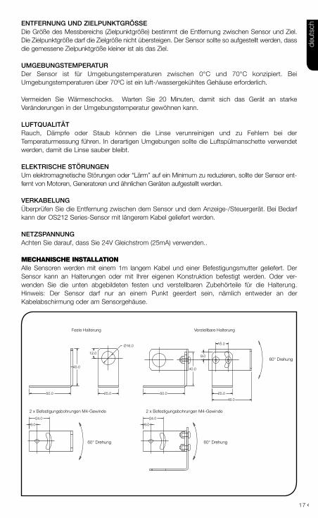
mecHanIscHe InstallatIonAlle Sensoren werden mit einem 1m langem Kabel und einer Befestigungsmutter geliefert. Der Sensor kann an Halterungen oder mit lhrer eigenen Konstruktion befestigt werden. Oder ver-wenden Sie die unten abgebildeten festen und verstellbaren Zubehörteile für die Halterung. Hinweis: Der Sensor darf nur an einem Punkt geerdert sein, nämlich entweder an der Kabelabschirmung oder am Sensorgehäuse.
12.0
45.0
50.0 50.0
40.0
9.0
15.0
25.0 25.0
9.0
48.0
9.0
24.024.0
Ø16.0
60° Drehung 60° Drehung
60° Drehung
Feste Halterung Verstellbare Halterung
2 x Befestigungsbohrungen M4-Gewinde 2 x Befestigungsbohrungen M4-Gewinde
deut
sch
18 ›
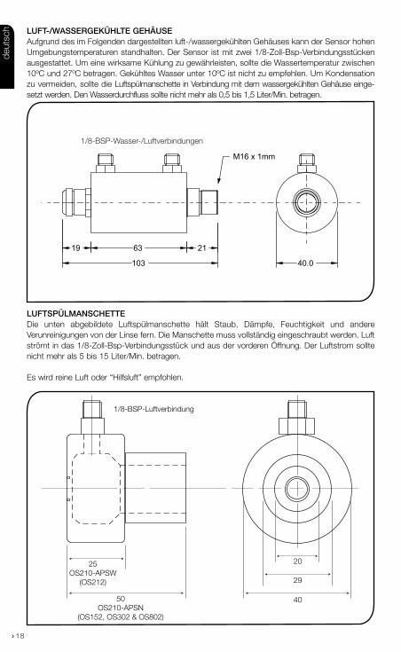
luft-/WassergeKühlte gehäuseAufgrund des im Folgenden dargestellten luft-/wassergekühlten Gehäuses kann der Sensor hohen Umgebungstemperaturen standhalten. Der Sensor ist mit zwei 1/8-Zoll-Bsp-Verbindungsstücken ausgestattet. Um eine wirksame Kühlung zu gewährleisten, sollte die Wassertemperatur zwischen 10ºC und 27ºC betragen. Gekühltes Wasser unter 10ºC ist nicht zu empfehlen. Um Kondensation zu vermeiden, sollte die Luftspülmanschette in Verbindung mit dem wassergekühlten Gehäuse einge-setzt werden. Den Wasserdurchfluss sollte nicht mehr als 0,5 bis 1,5 Liter/Min. betragen.
luftspülManschetteDie unten abgebildete Luftspülmanschette hält Staub, Dämpfe, Feuchtigkeit und andere Verunreinigungen von der Linse fern. Die Manschette muss vollständig eingeschraubt werden. Luft strömt in das 1/8-Zoll-Bsp-Verbindungsstück und aus der vorderen Öffnung. Der Luftstrom sollte nicht mehr als 5 bis 15 Liter/Min. betragen.
Es wird reine Luft oder “Hilfsluft” empfohlen.
40.0
2119 63
103
M16 x 1mm
1/8-BSP-Wasser-/Luftverbindungen
20
29
40
1/8-BSP-Luftverbindung
25OS210-APSW
(OS212)
50OS210-APSN
(OS152, OS302 & OS802)
deut
sch

19
› elektrIscHe InstallatIon
BetrieBWenn der Sensor aufgestellt ist und die entsprechenden Strom-, Luft-, Wasser- und Kabelanschlüsse gesichert sind, kann das System mit den folgenden einfachen Schritten auf Dauerbetrieb eingestellt werden:1. Die Stromversorgung einschalten2. Das Messgerät, den Rekorder oder Messumformer einschalten3. Die Temperatur ablesen / überwachen
WicHtigAchten Sie beim Einsatz des Sensors auf die folgenden Punkte:• Wenn der Sensor erheblichen Temperaturschwankungen ausgesetzt wird (heiss/kalt oder kalt/heiss),
sind 20 Minuten notwendig, damit sich die Temperatur vor der Temperaturmessung und -aufzeich-nung stabilisieren kann.
• Betreiben Sie den Sensor nicht in der Nähe großer elektromagnetischer Felder (z.B. von Lichtbogenschweißgeräten oder Induktionsheizgeräten). Elektromagnetische Störungen können zu Messfehlern führen.
• Die Kabel dürfen nur mit den korrekten Anschlüssen verbunden werden.
+ - -
+
4-20mA = Zieltemperatur
Stromzuführung
Stromzuführung
- SC 0V 24V
-
+
+
4-20mA = Emmissionsvermögen
OS212 Series Sensor
IP-
IP+
PWR+
PWR-
Display/Controller
OS210-PT/ PLC
4-20mA
4-20mA
deut
sch

20 ›
WartungUnsere Kundendienstmitarbeiter können bei Anwendungen, kalibrierung, Reparaturen und Lösung konk-reter Probleme helfen. Setzen Sie sich bitte mit unserer Kundendienstabteilung in Verbindung, bevor Sie Geräte zurücksenden. Häufig können Probleme telefonisch gelöst werden.Wenn der Sensor nicht ord-nungsgemäß funktioniert, versuchen Sie, das unten aufgeführte Symptom dem entsprechenden Problem zuzuordnen. Wenn die Tabelle nicht weiterhilft, kann Ihnen Omega möglicherweise telefonisch weitere Tipps geben.
Störungssuche
Symptom Wahrscheinliche ursache Lösung
Kein Ausgangssigna Keine Stromzufuhr am Sensor Stromanschluss überprüfen
Falsche Temperatur Falscher Kabelanschluss Kabelfarbcode überprüfen
Falsche Temperatur Fehlerhaftes Sensorkabel Kabelkontinuität überprüfen
Falsche Temperatur Blickfeld blockiert Blockierung entfernen
reinigen Der LinSeHalten Sie die Linse stets sauber. Fremdkörper auf der Linse würden die Messgenauigkeit beeinträchti-gen. Blasen Sie lose Partikel mit einem Gebläse von der Linse (sofern Sie nicht die Luftspülmanschette verwenden).
deut
sch

21
›Los sensores infrarrojos sin contacto OS212 Series miden temperaturas entre -20 °C y 500 °C y proporcionan una salida lineal de 4 a 20mA. Esta señal de salida es compatible con prácticamente cualquier indicador, controlador, registrador, registrador de datos, etc. sin que sea necesario utilizar ninguna interfaz específica ni una adaptación especial de la señal.
El ajuste de emisividad del sensor puede regularse de 0,2 a 1,0 para adaptarlo a distintos materi-ales y se controla con una entrada de 4-20 mA. Esto permite regular el ajuste de emisividad de manera automática desde un controlador lógico programable (PLC). De manera alternativa, el ajuste de emisividad puede regularse manualmente usando el módulo opcional OS210-PT. En caso de que se deje abierta la entrada 4-20 mA o que se produzca un cortocircuito, el ajuste de emisividad se regulará de manera predeterminada a 0,95.
caracteríSticaS - OS212 SerieS
tabla de rango de temperaturas frente a campo de visualizacióncampo Visual -20ºc a 100ºc 0ºc a 250ºc 0ºc a 500ºc
2:1 OS212-LT OS212-MT -15:1 OS152-LT OS152-MT OS152-HT30:1 OS302-LT OS302-MT OS302-HTø5mm @ 100mm OS802-LT OS802-MT OS802-HT
salida 4 a 20mAprecisión ±1% de lectura o ±1ºC, la cifra que sea mayorrepetibilidad ±0,5% de lectura o ±0,5ºC, la cifra que sea mayoremisividad ajustable de 0.2 a 1,0tiempo de respuesta 240ms (90% respuesta)respuesta espectral 8 a 14μmtensión de alimentación 24Vcc (máx. 28Vcc)tensión del sensor mín. 6Vccimpedancia máxima de circuito 900 Ohmios (4-20mA Salida)impedancia de entrada 50 ΩMecánicaConstrucción Acero inoxidableDimensiones 18mm de diámetro x 103mmLongitud de cable 1mPeso con cable 95gaMbienteValoración ambiental IP65Gama de temperatura ambiental 0ºC a 70ºCHumedad relativa 95% máximo sin condensación
caracteríSticaS - OS210-ptsalida 4 a 20mAtensión de alimentación 24 V cc (13V a 28V cc)formato de la pantalla LCD de 3,5 dígitosunidades mostradas Emisividad (0,2 a 1,0) o corriente (4 - 20 mA)ajuste Botones (levantado/bajado/fijado)Mecánicaconstrucción Policarbonato con junta, tapa transparente (PC) y tornillos de liberación rápidaMontaje SuperficieDimensiones 65 mm x 50 mm x 35 mmPeso 72 gaMbienteValoración ambiental IP65Gama de temperatura ambiental 0ºC a 70ºCHumedad relativa 95% máximo sin condensación
espa
ñol

22 ›
InstalacIÓnEl proceso de instalación consiste en las siguientes etapas: Preparación Instalación mecánica Instalación eléctricaLeer las siguientes secciones con detenimiento antes de proceder a la instalación.
preparacIÓnAsegurarse de que el sensor se coloca de manera que esté enfocando solamente a la diana.
accesorIosSe encuentra disponible una gama de accesorios para las distintas aplicaciones y ambientes industriales. Los accesorios pueden pedirse en cualquier momento y añadirse en el mismo recinto. Éstos consisten en las piezas a siguientes: Consola fija para el montaje Consola regulable de montaje Aro de purga de aire Herramienta de enfoque laser
opcIonesSe encuentran a disposición las siguientes opciones. Las opciones son instaladas en la fábrica y deben pedirse con el sensor OS212 Series. Caja de enfriamiento por aire/agua Certificado de calibración Cable más largo (máx. de 30 m)
cUaDro ÓptIcoEl cuadro óptico de debajo indica el diámetro nominal del punto de diana a una distancia dada de la cabeza sensora y asume 90% de energía.
Sensor
MEJOR
BUENO
INCORRECTO
Fondo
Diana superior al tamaño del punto
Diana igual al tamaño del punto
Diana inferior al tamaño del punto
1000
103
12
18
M16 x 1mm
Distancia: sensor a objeto (inches)
Distancia: sensor a objetot (mm)
11.945.2
78.6
0.51.8
3.1
0 19.7 39.4
0
11.9
0 500 1000
Diá
met
ro d
el
punt
o de
dia
na(in
ches
)
Diá
met
ro d
el
punt
o de
dia
na(m
m)
Diá
met
ro d
el
punt
o de
dia
na(in
ches
)
Diá
met
ro d
el
punt
o de
dia
na(m
m)
Distancia: sensor a objeto (inches)
Distancia: sensor a objetot (mm)
Diá
met
ro d
el
punt
o de
dia
na(in
ches
)
Diá
met
ro d
el
punt
o de
dia
na(m
m) Distancia: sensor a objeto (inches)
Distancia: sensor a objetot (mm)
11.9
0.5
61.9111.9
0.52.4
4.40 4 8
0
0
5.0
0.20
100
3.9
12.5
0.49
200
7.9
100 200
D:S 15:1D:S 2:1
Distancia: sensor a objeto (inches)
Distancia: sensor a objetot (mm)
11.928.6 45.2
0.51.1 1.8
0 19.7 39.4
0 500 1000
Diá
met
ro d
el
punt
o de
dia
na(in
ches
)
Diá
met
ro d
el
punt
o de
dia
na(m
m)
D:S 30:1
OS212 OS152 OS302 OS802
espa
ñol

23
›Distancia y taMaño De la zona De MeDiciónEl tamaño de la zona de medición a medir determina la distancia entre el sensor y la diana. El tamaño de la zona de medición no debe ser mayor que el de la diana. El sensor debe ser instalado de manera que la zona de medición determinada sea menor que la diana.
la teMperatura aMbienteEl sensor está diseñado para funcionar en temperaturas ambientes desde 0ºC hasta 70ºC. Para las temperaturas ambientes superiores a 70ºC, se hará necesario una caja de enfriamiento por aire/agua.
Evitar un cambio brusco de temperatura. Dejar pasar 20 minutos para que la unidad se ajuste a los grandes cambios de temperatura ambiente.
caliDaD atMosféricaLos humos o el polvo pueden contaminar la lente y causar errores en la medición de la temper-atura. El aro de purga de aire debe usarse en ambientes de este tipo para ayudar a mantener la lente limpia.
interferencia eléctrica Para reducir al mínimo la interferencia electromagnética o el “ruido”, el sensor debe ser instalado alejado de motores, generadores o similares.
conexiones eléctricasComprobar la distancia entre el sensor y el dispositivo indicador/controlador. Si es necesario, el sensor OS212 Series se puede pedir con el cable que viene adosado, más largo.
suMinistro eléctricoAsegurarse de usar un suministro eléctrico de 24Vcc, (25mA).
InstalacIÓn mecánIcaTodos los sensores vienen con 1 metro de cable y una tuerca de montaje. OS212 Series sensor puede ser instalado en una consola o dispositivos de diseño propio, o puede usar los accesorios de consola fija y regulable de montaje que se muestran debajo. Nota: El sensor debe ser conecta-do a la tierra en un único punto, en el blindaje del cable o en la carcasa del sensor.
12.0
45.0
50.0 50.0
40.0
9.0
15.0
25.0 25.0
9.0
48.0
9.0
24.024.0
Ø16.0
Rotación 60° Rotación 60°
Rotación 60°
Soporte fijo Soporte regulable
2 x Holgura de orificios de montaje M4 2 x Holgura de orificios de montaje M4
espa
ñol

24 ›
caja De enfriaMiento por aire/aguaLa caja de enfriamiento por aire/agua mostrada a continuación permite al sensor soportar temper-aturas ambientes elevadas. Se encuentra equipado de dos accesorios BSP (hilo de rosca en paralelo de British Standards) de 1/8 de pulgada. La temperatura del agua debe ser de 10ºC a 27ºC para un enfriamiento eficaz. No se recomienda agua fría por debajo de los 10ºC. Para evitar una condensación, el aro de purga de aire debe usarse con la caja de enfriamiento por agua. El caudal de agua no debe ser superior a 0,5 a 1,5 litros/min.
aro De purga De aireEl aro de purga de aire a continuación se usa para mantener el polvo, los humos, la humedad y otros contaminantes alejados de la lente. Debe atornillase completamente. El aire fluye hacia adentro del accesorio BSP de 1/8 de pulgada y hacia afuera de la abertura frontal. El flujo de aire no debe ser superior a 5 a 15 litros/min.
Se recomienda aire limpio o “para instrumentos”.
40.0
2119 63
103
M16 x 1mm
Conexiones de agua/aire de BSP (hilo de rosca en paralelo de British Standards)
de 1/8 de pulgada.
20
29
40
Conexiones de aire de BSP (hilo de rosca en paralelo de British Standards) de 1/8 de pulgada.
25APSW(PE21)
50APSN
(PE151, PE301, PECF)
espa
ñol

25
›InstalacIÓn eléctrIca
funcionaMientoUna vez que el sensor está en posición y el suministro eléctrico, el aire, el agua y las conexiones de cables apropiadas están seguras, el sistema está listo para el funcionamiento continuo, una vez se completen los sencillos pasos siguientes:
1. Encender el suministro eléctrico2. Encender el medidor, el registro gráfico o el controlador3. Leer / controlar la temperatura
iMportantePrestar atención a lo siguiente al usar el sensor:• Si el sensor se expone a cambios significativos de temperatura ambiental (de caliente a fr’o o
de fr’o a caliente), dejar pasar 20 minutos para que la temperatura se estabilice antes de tomar o registrar temperaturas.
• No hacer funcionar el sensor cerca de grandes campos electromagnéticos (ejemplo, cerca de soldadoras por arco o calentadores por corrientes de inducción). Las interferencias electro-magnéticas pueden causar errores de medición.
• Los hilos deben ser conectados solamente a las terminales apropiadas.
+ - -
+
4-20mA = Temperaturaobjetivo
Suministro eléctrico
Suministro eléctrico
- SC 0V 24V
-
+
+
4-20mA = Emisividad
Sensor OS212 Series
IP-
IP+
PWR+
PWR-
Indicador/Controlador
OS210-PT/ PLC
4-20mA
4-20mA
espa
ñol

26 ›
ManteniMientoNuestros representantes de servicio al cliente están a su disposición para asistirles en aplica-ciones, calibración, reparación y soluciones a problemas específicos. Contactar nuestro Departamento de servicio antes de devolver el equipo. En muchos casos, los problemas pueden resolverse por teléfono. Si el sensor no funciona como debiera, intentar encontrar el síntoma de entre los siguientes para identificar su problema. Si la tabla no le sirve de ayuda, llamar a Omega para mayor asistencia.
identificación de problemas
síntoma causa probable solución
No funciona No hay suministro eléctrico al sensor
Comprobar el suministro eléctrico
Temperatura errónea Conexión de cables incorrecta
Comprobar los códigos de color de los cables
Temperatura errónea Cable sensor defectuoso Confirmar la continuidad de los cables
Temperatura errónea Obstrucción del campo visual Retirar obstrucción
liMpieza De la lenteMantener la lente limpia en todo momento. Cualquier materia extraña en la lente afectaría la pre-cisión de medición. Soplar las partículas sueltas (si no se usa el accesorio de purga de aire) con un ‘soplador’ de aire.
espa
ñol
27
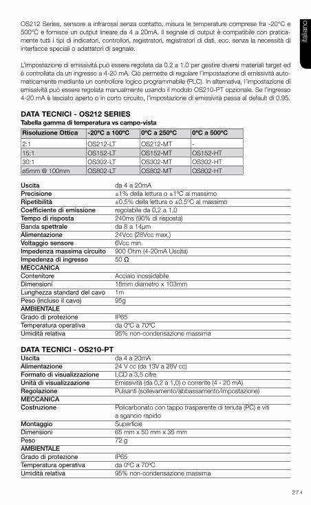
›OS212 Series, sensore a infrarossi senza contatto, misura le temperature comprese fra -20°C e 500°C e fornisce un output lineare da 4 a 20mA. Il segnale di output è compatibile con pratica-mente tutti i tipi di indicatori, controllori, registratori, registratori di dati, ecc. senza la necessità di interfacce speciali o adattatori di segnale.
L’impostazione di emissività può essere regolata da 0.2 a 1.0 per gestire diversi materiali target ed è controllata da un ingresso a 4-20 mA. Ciò permette di regolare l’impostazione di emissività auto-maticamente mediante un controllore logico programmabile (PLC). In alternativa, l’impostazione di emissività può essere regolata manualmente usando il modulo OS210-PT opzionale. Se l’ingresso 4-20 mA è lasciato aperto o in corto circuito, l’impostazione di emissività passa al default di 0.95.
Data tecnici - OS212 SerieStabella gamma di temperatura vs campo-vista
risoluzione Ottica -20ºc a 100ºc 0ºc a 250ºc 0ºc a 500ºc
2:1 OS212-LT OS212-MT -15:1 OS152-LT OS152-MT OS152-HT30:1 OS302-LT OS302-MT OS302-HTø5mm @ 100mm OS802-LT OS802-MT OS802-HT
uscita da 4 a 20mAprecisione ±1% della lettura o ±1ºC al massimoripetibilità ±0.5% della lettura o ±0.5ºC al massimocoefficiente di emissione regolabile da 0,2 a 1,0tempo di risposta 240ms (90% di risposta)Banda spettrale da 8 a 14μmalimentazione 24Vcc (28Vcc max.)voltaggio sensore 6Vcc min.impedenza massima circuito 900 Ohm (4-20mA Uscita)impedenza di ingresso 50 ΩMeccanicaContenitore Acciaio inossidabileDimensioni 18mm diametro x 103mmLunghezza standard del cavo 1mPeso (incluso il cavo) 95gaMbientaleGrado di protezione IP65Temperatura operativa da 0ºC a 70ºC Umidità relativa 95% non-condensazione massima
Data tecnici - OS210-ptuscita da 4 a 20mAalimentazione 24 V cc (da 13V a 28V cc)formato di visualizzazione LCD a 3,5 cifreunità di visualizzazione Emissività (da 0,2 a 1,0) o corrente (4 - 20 mA)regolazione Pulsanti (sollevamento/abbassamento/impostazione)Meccanicacostruzione Policarbonato con tappo trasparente di tenuta (PC) e viti a sgancio rapidoMontaggio SuperficieDimensioni 65 mm x 50 mm x 35 mmPeso 72 gaMbientaleGrado di protezione IP65Temperatura operativa da 0ºC a 70ºC Umidità relativa 95% non-condensazione massima
italia
no
28 ›
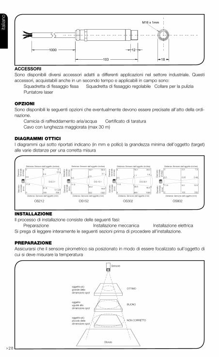
acceSSOriSono disponibili diversi accessori adatti a differenti applicazioni nel settore industriale. Questi accessori, acquistabili anche in un secondo tempo e applicabili in campo sono: Squadretta di fissaggio fissa Squadretta di fissaggio regolabile Collare per la pulizia Puntatore laser
opZIonISono disponibili le seguenti opzioni che eventualmente devono essere precisate all’atto della ordi-nazione. Camicia di raffreddamento aria/acqua Certificato di taratura Cavo con lunghezza maggiorata (max 30 m)
DIaGrammI ottIcI I diagrammi qui sotto riportati indicano (in mm e pollici) la grandezza minima dell’oggetto (target) alle varie distanze per una corretta misura
InstallaZIoneIl processo di installazione consiste delle seguenti fasi: Preparazione Installazione meccanica Installazione elettricaSi prega di leggere interamente le seguenti sezioni prima di procedere all’installazione.
preparaZIoneAssicurarsi che il sensore pirometrico sia posizionato in modo di essere focalizzato sull’oggetto di cui si deve misurare la temperatura
Sensore
OTTIMO
BUONO
NON CORRETTO
Sfondo
oggetto più grande della dimensione spot
oggetto uguale alla dimensione spot
oggetto più piccolo della dimensione spot
1000
103
12
18
M16 x 1mm
Distanza: Sensore dall’oggetto (inches)
Distanza: Sensore dall’oggetto (mm)
11.945.2
78.6
0.51.8
3.1
0 19.7 39.4
0
11.9
0 500 1000
Dia
met
ro
nom
inal
e(in
ches
)
Dia
met
ro
nom
inal
e(m
m)
Dia
met
ro
nom
inal
e(in
ches
)
Dia
met
ro
nom
inal
e(m
m)
Distanza: Sensore dall’oggetto (inches)
Distanza: Sensore dall’oggetto (mm)
Dia
met
ro
nom
inal
e(in
ches
)
Dia
met
ro
nom
inal
e(m
m)
Distanza: Sensore dall’oggetto (inches)
Distanza: Sensore dall’oggetto (mm)
11.9
0.5
61.9111.9
0.52.4
4.40 4 8
0
0
5.0
0.20
100
3.9
12.5
0.49
200
7.9
100 200
D:S 15:1D:S 2:1
Distanza: Sensore dall’oggetto (inches)
Distanza: Sensore dall’oggetto (mm)
11.928.6 45.2
0.51.1 1.8
0 19.7 39.4
0 500 1000
Dia
met
ro
nom
inal
e(in
ches
)
Dia
met
ro
nom
inal
e(m
m)
D:S 30:1
OS212 OS152 OS302 OS802
italia
no

29
›Distanza e DiMensione spot In base al cono utile (spot) che parte dal sensore ( vedi disegno nella pagina precedente) la dimen-sione dell’area da misurare determina la distanza tra sensore e oggetto. L’oggetto non deve essere più grande dello spot, in questo caso si deve allontanare il sensore dall’oggetto fino che lo stesso risulta uguale o più piccolo dello spot.
teMperatura aMbiente Il sensore può lavorare a temperatura ambiente compresa tra 0°C e 70°C. Per temperatura ambi-ente superiore si deve usare la camicia di raffreddamento.
Evitare shock termici. Aspettare circa 20 minuti per adeguare il sensore pirometrico alla temper-atura dell’ambiente.
Qualita’ atMosferica Se nell’ambiente l’aria è impregnata di fumo o di impurità usare il collare di raffreddamento per pulire l’ottica del sensore.
inteeferenze elettriche Per evitare interferenze e disturbi causati dai campi elettromagnetici posizionare il sensore lontano da motori, cavi di alta tensione, ecc.
cablaggioControllare la distanza tra il sensore pirometrico e l’utilizzazione. In caso di distanza maggiore di 1m precisare la lunghezza opzionale del cavo.
aliMentazione Controllare che l’alimentazione sia 24 Vcc (22mA)
InstallaZIone meccanIca I sensori sono forniti con cavo di 1 m e dado di fissaggio per il montaggio sulla parte terminale filettata tramite squadrette fisse o regolabili come quelle fornibili dalla casa e qui sotto riportate. NOTA BENE: Il sensore deve essere messo a terra solo su un punto: o sul cavo schermato o dal contenitore del sensore.
12.0
45.0
50.0 50.0
40.0
9.0
15.0
25.0 25.0
9.0
48.0
9.0
24.024.0
Ø16.0
Rotazione 60° Rotazione 60°
Rotazione 60°
Squadretta fissa Squadretta regolabile
Fori di montaggio M4 Fori di montaggio M4
italia
no

30 ›
caMicia Di raffreDDaMento aria/acQua Questa opzione deve essere montata in fabbrica sul sensore e permette di sopportare elevate temperature ambiente. L’acqua (o l’aria compressa) viene fatta defluire tramite i 2 manicotti BSP 1/8” di ingresso e di uscita. Con acqua tra 10°C e 27°C si può installare il sensore ad una tem-peratura ambiente di 200°C/250°C. si raccomanda di non usare acqua fredda al di sotto di 10°C per evitare condensa sull’ottica. In questo caso si può usare il collare di pulizia (vedi sotto). La portata d’acqua non deve superare 0,5 a 1,5 litri/min.
collare Di pulizia aD ariaCon questo accessorio tramite il suo manicotto BSP 1/8” si può insufflare aria compressa (por-tata raccomandata tra 5 e 15 litri/min.). L’aria fuoriesce dalla superficie frontale del collare tenendo pulita l’ottica retrostante il collare montato sul sensore. Il montaggio del collare sul sensore è a vite sull’interno filettato.
L’aria compressa inviata deve essere pulita e filtrata.
40.0
2119 63
103
M16 x 1mm
Connessioni aria/acqua BSP 1/8”
20
29
40
Connessione aria BSP 1/8”
25OS210-APSW
(OS212)
50OS210-APSN
(OS152, OS302 & OS802)
italia
no

31
›InstallaZIone elettrIca
FUnZIonamentoInstallato il sensore e collegato alla rete elettrica ed eventualmente ai circuiti di raffreddamento, si procede a: 1 Accendere l’alimentazione (accertarsi che sia 24 Vcc!2. Dare tensione all’utilizzazione (es. visualizzatore) 3. Leggere e controllare la temperatura sul visualizzatore
avvertenze• Se la temperatura della zona nel quale è installato il sensore è superiore (o inferiore) alla tem-
peratura ambiente di 10/24°C attendere circa 20 minuti per il tempo di stabilizzazione neces-sario per avere misure affidabili
• Non azionare il sensore in prossimità di consistenti campi elettromagnetici (p.e. vicino ad archi voltaici o forni a induzione). I disturbi elettromagnetici possono causare errori rilevanti della misura
• Accertarsi in anticipo che i cablaggi elettrici siano fatti sui terminali giusti.
+ - -
+
4-20mA = Temperaturamirata
Alimentazione
Alimentazione
- SC 0V 24V
-
+
+
4-20mA = Coefficiente diemissione
OS212 Series Sensore
IP-
IP+
PWR+
PWR-
Combinatore/indicatore
4-20mA
4-20mA
OS210-PT/ PLC
italia
no

32 ›
manUtenZIoneSalvo che per una periodica pulizia dell’ottica il OS212 Series non richiede una particolare manutenzione. In caso di cattivo funzionamento chiedere all’agente locale consigli per l’eliminazione del problema avvalendosi della sottostante tabella diagnostica. Solo in caso di non risolvere il problema dopo questo contatto rimandare il sensore alla Casa o all’agente locale per un più appro-fondito controllo.
identificazione dei problemi i
problema causa probabile soluzione
Manca l’uscita Sensore non alimentato Controllo alimentazione
Misura non corretta Fili mal collegati Controllo colore del filo
Misura non corretta Cavo sensore difettoso Verifica continuità del cavo
Misura non corretta Ostruzione campo visivo Rimuovere ostruzione
pulizia Dell’ottica Mantenere la lente sempre pulita. Depositi sulla lente influenzano la misura. Se il sensore non è dotato del collare di pulizia e vi sono particelle solide usare un getto di aria o un panno bagnato d’acqua non contenente abrasivi.
italia
no

WARRANTY/DISCLAIMEROMEGA ENGINEERING, INC. warrants this unit to be free of defects in materials andworkmanship for a period of 37 months from date of purchase. OMEGA’s WARRANTYadds an additional one (1) month grace period to the normal three (3) year productwarranty to cover handling and shipping time. This ensures that OMEGA’s customersreceive maximum coverage on each product. If the unit malfunctions, it must be returned to the factory for evaluation. OMEGA’sCustomer Service Department will issue an Authorized Return (AR) number immediatelyupon phone or written request. Upon examination by OMEGA, if the unit is found to bedefective, it will be repaired or replaced at no charge. OMEGA’s WARRANTY does not applyto defects resulting from any action of the purchaser, including but not limited tomishandling, improper interfacing, operation outside of design limits, improper repair, orunauthorized modification. This WARRANTY is VOID if the unit shows evidence of havingbeen tampered with or shows evidence of having been damaged as a result of excessivecorrosion; or current, heat, moisture or vibration; improper specification; misapplication;misuse or other operating conditions outside of OMEGA’s control. Components in whichwear is not warranted, include but are not limited to contact points, fuses, and triacs.OMEGA is pleased to offer suggestions on the use of its various products.However, OMEGA neither assumes responsibility for any omissions or errors norassumes liability for any damages that result from the use of its products inaccordance with information provided by OMEGA, either verbal or written.OMEGA warrants only that the parts manufactured by the company will be asspecified and free of defects. OMEGA MAKES NO OTHER WARRANTIES ORREPRESENTATIONS OF ANY KIND WHATSOEVER, EXPRESSED OR IMPLIED,EXCEPT THAT OF TITLE, AND ALL IMPLIED WARRANTIES INCLUDING ANYWARRANTY OF MERCHANTABILITY AND FITNESS FOR A PARTICULAR PURPOSEARE HEREBY DISCLAIMED. LIMITATION OF LIABILITY: The remedies ofpurchaser set forth herein are exclusive, and the total liability of OMEGA withrespect to this order, whether based on contract, warranty, negligence,indemnification, strict liability or otherwise, shall not exceed the purchase priceof the component upon which liability is based. In no event shall OMEGA beliable for consequential, incidental or special damages.CONDITIONS: Equipment sold by OMEGA is not intended to be used, nor shall it be used:(1) as a “Basic Component” under 10 CFR 21 (NRC), used in or with any nuclear installationor activity; or (2) in medical applications or used on humans. Should any Product(s) be usedin or with any nuclear installation or activity, medical application, used on humans, ormisused in any way, OMEGA assumes no responsibility as set forth in our basicWARRANTY / DISCLAIMER language, and, additionally, purchaser will indemnify OMEGAand hold OMEGA harmless from any liability or damage whatsoever arising out of the useof the Product(s) in such a manner.
RETURN REQUESTS/INQUIRIESDirect all warranty and repair requests/inquiries to the OMEGA Customer ServiceDepartment. BEFORE RETURNING ANY PRODUCT(S) TO OMEGA, PURCHASER MUSTOBTAIN AN AUTHORIZED RETURN (AR) NUMBER FROM OMEGA’S CUSTOMER SERVICEDEPARTMENT (IN ORDER TO AVOID PROCESSING DELAYS). The assigned AR numbershould then be marked on the outside of the return package and on any correspondence.The purchaser is responsible for shipping charges, freight, insurance and proper packagingto prevent breakage in transit.
FOR WARRANTY RETURNS, pleasehave the following informationavailable BEFORE contacting OMEGA:1. Purchase Order number under which
the product was PURCHASED,2. Model and serial number of the
product under warranty, and3. Repair instructions and/or specific
problems relative to the product.
FOR NON-WARRANTY REPAIRS, consult OMEGAfor current repair charges. Have the followinginformation available BEFORE contacting OMEGA:1. Purchase Order number to cover the
COST of the repair,2. Model and serial number of the
product, and3. Repair instructions and/or specific problems
relative to the product.OMEGA’s policy is to make running changes, not model changes, whenever an improvement is possible. This affords our customers the latest in technology and engineering.OMEGA is a registered trademark of OMEGA ENGINEERING, INC.© Copyright 2011 OMEGA ENGINEERING, INC. All rights reserved. This document may not be copied, pho-tocopied, reproduced, translated, or reduced to any electronic medium or machine-readable form, in wholeor in part, without the prior written consent of OMEGA ENGINEERING, INC.

Where Do I Find Everything I Need forProcess Measurement and Control?
OMEGA…Of Course!Shop online at omega.com SM
TEMPERATUREThermocouple, RTD & Thermistor Probes, Connectors, Panels & AssembliesWire: Thermocouple, RTD & ThermistorCalibrators & Ice Point ReferencesRecorders, Controllers & Process MonitorsInfrared Pyrometers
PRESSURE, STRAIN AND FORCETransducers & Strain GagesLoad Cells & Pressure GagesDisplacement TransducersInstrumentation & Accessories
FLOW/LEVELRotameters, Gas Mass Flowmeters & Flow ComputersAir Velocity IndicatorsTurbine/Paddlewheel SystemsTotalizers & Batch Controllers
pH/CONDUCTIVITYpH Electrodes, Testers & AccessoriesBenchtop/Laboratory MetersControllers, Calibrators, Simulators & PumpsIndustrial pH & Conductivity Equipment
DATA ACQUISITIONData Acquisition & Engineering SoftwareCommunications-Based Acquisition SystemsPlug-in Cards for Apple, IBM & CompatiblesData Logging SystemsRecorders, Printers & Plotters
HEATERSHeating CableCartridge & Strip HeatersImmersion & Band HeatersFlexible HeatersLaboratory Heaters
ENVIRONMENTALMONITORING AND CONTROL
Metering & Control InstrumentationRefractometersPumps & TubingAir, Soil & Water MonitorsIndustrial Water & Wastewater TreatmentpH, Conductivity & Dissolved Oxygen Instruments
M5067/1211