show ip nbar port-map - · pdf fileshow ip nbar port-map ... to display the ip precedence bit...
TRANSCRIPT
show ip nbar port-map
QR-263Cisco IOS Quality of Service Solutions Command Reference
78-11746-02
show ip nbar port-mapTo display the current protocol-to-port mappings in use by Network-Based Application Recognition (NBAR), use the show ip nbar port-map privileged EXEC command.
show ip nbar port-map [protocol-name]
Syntax Description
Defaults This command displays port assignments for NBAR protocols.
Command Modes Privileged EXEC
Command History
Usage Guidelines This command is used to display the current protocol-to-port mappings in use by NBAR. When the ip nbar port-map command has been used, the show ip nbar port-map command displays the ports assigned by the user to the protocol. If no ip nbar port-map command has been used, the show ip nbar port-map command displays the default ports. The protocol-name argument can also be used to limit the display to a specific protocol.
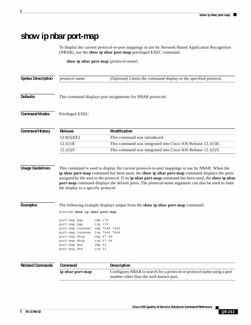
Examples The following example displays output from the show ip nbar port-map command:
Router# show ip nbar-port-map
port-map bgp udp 179 port-map bgp tcp 179 port-map cuseeme udp 7648 7649 port-map cuseeme tcp 7648 7649 port-map dhcp udp 67 68 port-map dhcp tcp 67 68 port-map dns udp 53 port-map dns tcp 53
Related Commands
protocol-name (Optional) Limits the command display to the specified protocol.
Release Modification
12.0(5)XE2 This command was introduced.
12.1(1)E This command was integrated into Cisco IOS Release 12.1(1)E.
12.1(5)T This command was integrated into Cisco IOS Release 12.1(5)T.
Command Description
ip nbar-port-map Configures NBAR to search for a protocol or protocol name using a port number other than the well-known port.

show ip nbar protocol-discovery
QR-264Cisco IOS Quality of Service Solutions Command Reference
78-11746-02
show ip nbar protocol-discoveryTo display the statistics gathered by the Network-Based Application Recognition (NBAR) Protocol Discovery feature, use the show ip nbar protocol-discovery privileged EXEC command.
show ip nbar protocol-discovery [interface interface-spec] [stats {byte-count | bit-rate | packet-count}][{protocol protocol-name | top-n number}]
Syntax Description
Defaults Statistics for all interfaces on which the Protocol Discovery feature is enabled are displayed.
Command Modes Privileged EXEC
Command History
Usage Guidelines Use the show ip nbar protocol-discovery command to display statistics gathered by the NBAR Protocol Discovery feature. This command, by default, displays statistics for all interfaces on which protocol discovery is currently enabled. The default output of this command includes, in the following order, input bit rate (in bits per second), input byte count, input packet count, and protocol name.
interface (Optional) Specifies that Protocol Discovery statistics for the interface are to be displayed.
interface-spec (Optional) Specifies an interface to display.
stats (Optional) Specifies that the byte count, byte rate, or packet count is to be displayed.
byte-count (Optional) Specifies that the byte count is to be displayed.
bit-rate (Optional) Specifies that the bit rate is to be displayed.
packet-count (Optional) Specifies that the packet-count is to be displayed.
protocol (Optional) Specifies that statistics for a specific protocol are to be displayed.
protocol-name (Optional) User-specified protocol name for which the statistics are to be displayed.
top-n (Optional) Specifies that a top-n is to be displayed. A top-n is the number of most active NBAR-supported protocols, where n is the number of protocols to be displayed. For instance, if top-n 3 is entered, the three most active NBAR-supported protocols will be displayed.
number (Optional) Specifies the number of most active NBAR-supported protocols to be displayed.
Release Modification
12.0(5)XE2 This command was introduced.
12.1(1)E This command was integrated into Cisco IOS Release 12.1(1)E.
12.1(5)T This command was integrated into Cisco IOS Release 12.1(5)T.
show ip nbar protocol-discovery
QR-265Cisco IOS Quality of Service Solutions Command Reference
78-11746-02
Protocol discovery can be used to monitor both input and output traffic and may be applied with or without a service policy enabled. NBAR protocol discovery gathers statistics for packets switched to output interfaces. These statistics are not necessarily for packets that exited the router on the output interfaces, because packets may have been dropped after switching for various reasons, including policing at the output interface, access lists, or queue drops.
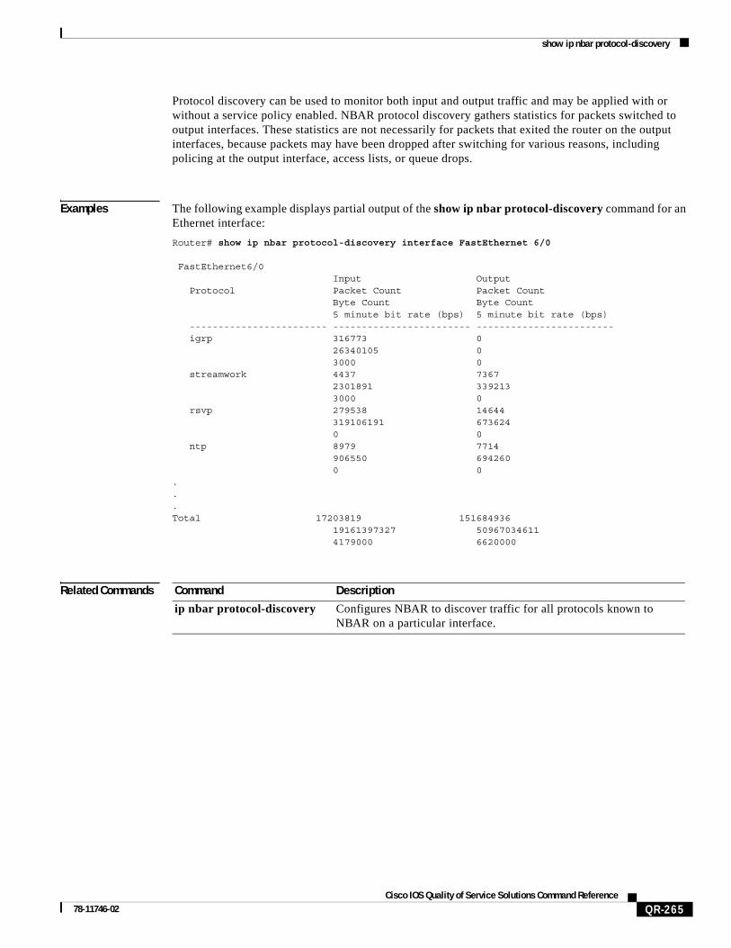
Examples The following example displays partial output of the show ip nbar protocol-discovery command for an Ethernet interface:
Router# show ip nbar protocol-discovery interface FastEthernet 6/0
FastEthernet6/0 Input Output Protocol Packet Count Packet Count Byte Count Byte Count 5 minute bit rate (bps) 5 minute bit rate (bps) ------------------------ ------------------------ ------------------------ igrp 316773 0 26340105 0 3000 0 streamwork 4437 7367 2301891 339213 3000 0 rsvp 279538 14644 319106191 673624 0 0 ntp 8979 7714 906550 694260 0 0 ...Total 17203819 151684936 19161397327 50967034611 4179000 6620000
Related Commands Command Description
ip nbar protocol-discovery Configures NBAR to discover traffic for all protocols known to NBAR on a particular interface.

show ip rsvp
QR-266Cisco IOS Quality of Service Solutions Command Reference
78-11746-02
show ip rsvpTo display the IP Precedence bit values and type of service (ToS) bit values to be used to mark the ToS byte of the IP headers of all packets in a Resource Reservation Protocol (RSVP) reserved path that conform to or exceed the RSVP flowspec for a given interface, use the show ip rsvp EXEC command.
show ip rsvp {precedence | tos} [interface-name]
Syntax Description
Command Modes EXEC
Command History
Usage Guidelines Use this command to show the current IP Precedence (or ToS) bit values set for traffic conforming to or exceeding the RSVP flowspec for an interface if the ip rsvp precedence or ip rsvp tos command was used to configure values for any Enhanced ATM port adapter (PA-A3) interface on the router.
Use this command to show the current ToS bit values set for traffic conforming to or exceeding the Resource Reservation Protocol (RSVP) flowspec for an interface if the ip rsvp tos command was used to configure values for any Enhanced ATM port adapter (PA-A3) interface on the router.
The show ip rsvp tos and show ip rsvp precedence commands are functionally equivalent. They both show the IP Precedence and ToS bit values for all interfaces with RSVP enabled.
To display these values for a given interface exclusively, specify the interface name. If the interface argument is omitted, IP Precedence and ToS bit values are displayed for all interfaces with RSVP enabled.
precedence Displays IP Precedence bit and ToS bit conform and exceed values for all interfaces on the router.
Either argument—precedence or tos—yields the same results. IP Precedence and ToS bit values for all interfaces with RSVP enabled are displayed in both cases.
Either tos or precedence may be specified; one is required.
tos Displays IP Precedence bit and ToS bit conform and exceed values for all interfaces on the router.
Either argument—precedence or tos—yields the same results. IP Precedence and ToS bit values for all interfaces with RSVP enabled are displayed in both cases.
Either tos or precedence may be specified; one is required.
interface-name (Optional) The name of the interface. If this argument is omitted, IP Precedence and ToS bit values are displayed for all interfaces with RSVP enabled.
Release Modification
12.0(3)T This command was introduced.
show ip rsvp
QR-267Cisco IOS Quality of Service Solutions Command Reference
78-11746-02
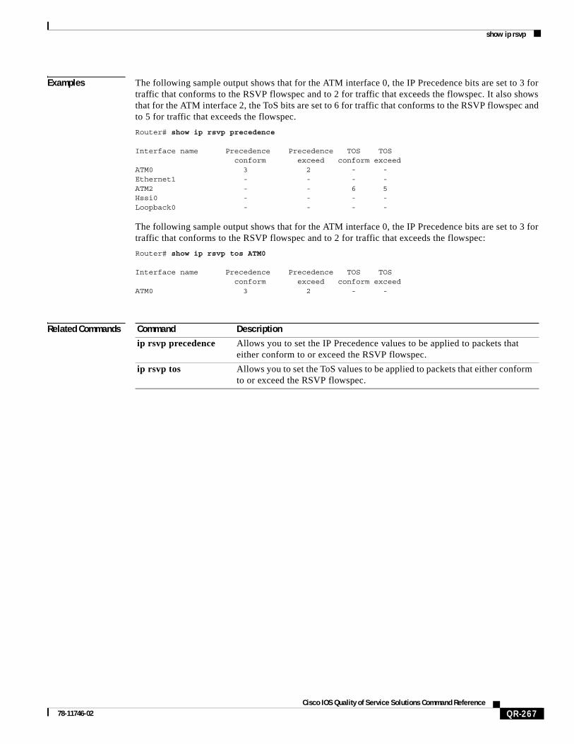
Examples The following sample output shows that for the ATM interface 0, the IP Precedence bits are set to 3 for traffic that conforms to the RSVP flowspec and to 2 for traffic that exceeds the flowspec. It also shows that for the ATM interface 2, the ToS bits are set to 6 for traffic that conforms to the RSVP flowspec and to 5 for traffic that exceeds the flowspec.
Router# show ip rsvp precedence
Interface name Precedence Precedence TOS TOS conform exceed conform exceedATM0 3 2 - -Ethernet1 - - - - ATM2 - - 6 5Hssi0 - - - - Loopback0 - - - -
The following sample output shows that for the ATM interface 0, the IP Precedence bits are set to 3 for traffic that conforms to the RSVP flowspec and to 2 for traffic that exceeds the flowspec:
Router# show ip rsvp tos ATM0
Interface name Precedence Precedence TOS TOS conform exceed conform exceedATM0 3 2 - -
Related Commands Command Description
ip rsvp precedence Allows you to set the IP Precedence values to be applied to packets that either conform to or exceed the RSVP flowspec.
ip rsvp tos Allows you to set the ToS values to be applied to packets that either conform to or exceed the RSVP flowspec.

show ip rsvp atm-peak-rate-limit
QR-268Cisco IOS Quality of Service Solutions Command Reference
78-11746-02
show ip rsvp atm-peak-rate-limitTo display the current peak rate limit set for an interface, if any, use the show ip rsvp atm-peak-rate-limit EXEC command.
show ip rsvp atm-peak-rate-limit [interface-name]
Syntax Description
Command Modes EXEC
Command History
Usage Guidelines The show ip rsvp atm-peak-rate-limit command displays the configured peak rate using the following notations for brevity:
• Kilobytes is shown as K bytes, for example, 1200 kilobytes is displayed as 1200K bytes.
• 1000 kilobytes is displayed as 1M bytes.
If no interface name is specified, configured peak rates for all Resource Reservation Protocol (RSVP)-enabled interfaces are displayed.
Examples The following example depicts results of the show ip rsvp atm-peak-rate-limit command, presuming that the ATM subinterface 2/0/0.1 was configured with a reservation peak rate limit of 100 KB using the ip rsvp atm-peak-rate-limit command.
The following is sample output from the show ip rsvp atm-peak-rate-limit command using the interface argument:
Router# show ip rsvp atm-peak-rate-limit atm2/0/0.1
RSVP: Peak rate limit for ATM2/0/0.1 is 100K bytes
The following samples show output from the show ip rsvp atm-peak-rate-limit command when no interface name is given:
Router# show ip rsvp atm-peak-rate-limit
Interface name Peak rate limitEthernet0/1/1 not setATM2/0/0 not setATM2/0/0.1 100K
interface-name (Optional) The name of the interface.
Release Modification
12.0(3)T This command was introduced.
show ip rsvp atm-peak-rate-limit
QR-269Cisco IOS Quality of Service Solutions Command Reference
78-11746-02
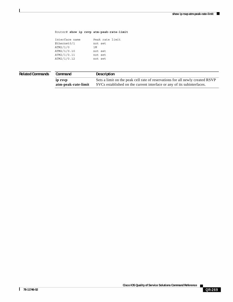
Router# show ip rsvp atm-peak-rate-limit
Interface name Peak rate limit Ethernet0/1 not set ATM2/1/0 1M ATM2/1/0.10 not set ATM2/1/0.11 not set ATM2/1/0.12 not set
Related Commands Command Description
ip rsvp atm-peak-rate-limit
Sets a limit on the peak cell rate of reservations for all newly created RSVP SVCs established on the current interface or any of its subinterfaces.

show ip rsvp installed
QR-270Cisco IOS Quality of Service Solutions Command Reference
78-11746-02
show ip rsvp installedTo display Resource Reservation Protocol (RSVP)-related installed filters and corresponding bandwidth information, use the show ip rsvp installed EXEC command.
show ip rsvp installed [detail][interface-type interface-number]
Syntax Description
Defaults This command has no default behavior or values.
Command Modes EXEC
Command History
Usage Guidelines The show ip rsvp installed command displays the current installed RSVP filters and the corresponding bandwidth information for a specified interface or all interfaces.
Examples The following is sample output from the show ip rsvp installed command:
Router# show ip rsvp installed
RSVP: RSVP: Ethernet1: has no installed reservationsRSVP: Serial0: kbps To From Protocol DPort Sport Weight Conversation 0 224.250.250.1 132.240.2.28 UDP 20 30 128 270 150 224.250.250.1 132.240.2.1 UDP 20 30 128 268 100 224.250.250.1 132.240.1.1 UDP 20 30 128 267 200 224.250.250.1 132.240.1.25 UDP 20 30 256 265 200 224.250.250.2 132.240.1.25 UDP 20 30 128 271 0 224.250.250.2 132.240.2.28 UDP 20 30 128 269 150 224.250.250.2 132.240.2.1 UDP 20 30 128 266 350 224.250.250.3 0.0.0.0 UDP 20 0 128 26
detail (Optional) Specifies additional information about interfaces and their reservations.
interface-type (Optional) Specifies the type of the interface.
interface-number (Optional) Specifies the number of the interface.
Release Modification
11.2 This command was introduced.
show ip rsvp installed
QR-271Cisco IOS Quality of Service Solutions Command Reference
78-11746-02
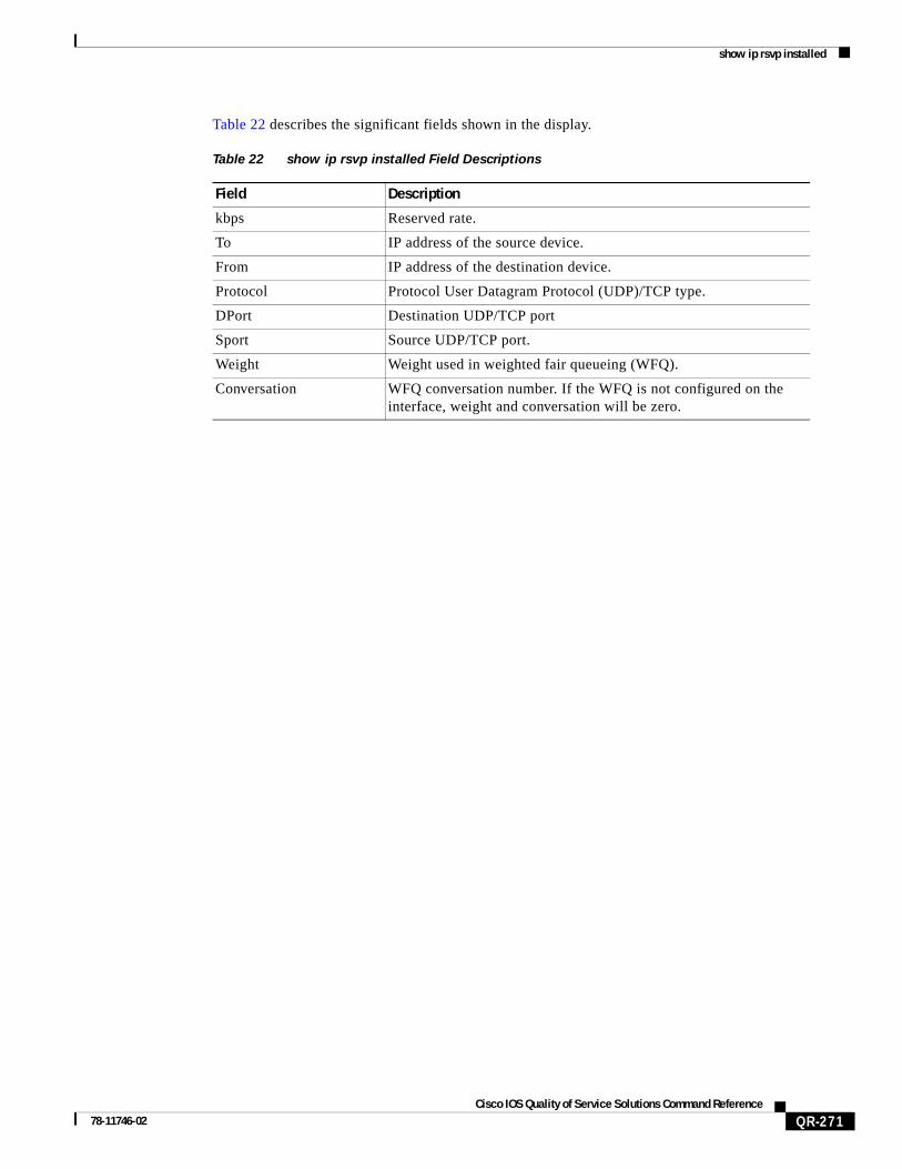
Table 22 describes the significant fields shown in the display.
Table 22 show ip rsvp installed Field Descriptions
Field Description
kbps Reserved rate.
To IP address of the source device.
From IP address of the destination device.
Protocol Protocol User Datagram Protocol (UDP)/TCP type.
DPort Destination UDP/TCP port
Sport Source UDP/TCP port.
Weight Weight used in weighted fair queueing (WFQ).
Conversation WFQ conversation number. If the WFQ is not configured on the interface, weight and conversation will be zero.
show ip rsvp interface
QR-272Cisco IOS Quality of Service Solutions Command Reference
78-11746-02
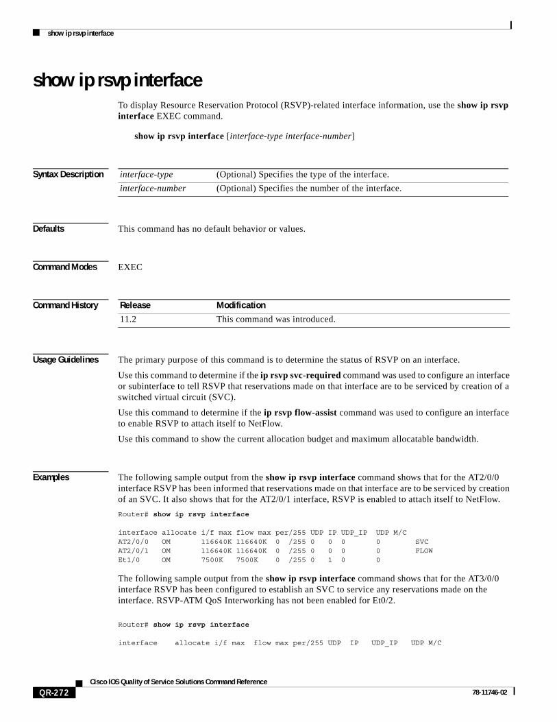
show ip rsvp interfaceTo display Resource Reservation Protocol (RSVP)-related interface information, use the show ip rsvp interface EXEC command.
show ip rsvp interface [interface-type interface-number]
Syntax Description
Defaults This command has no default behavior or values.
Command Modes EXEC
Command History
Usage Guidelines The primary purpose of this command is to determine the status of RSVP on an interface.
Use this command to determine if the ip rsvp svc-required command was used to configure an interface or subinterface to tell RSVP that reservations made on that interface are to be serviced by creation of a switched virtual circuit (SVC).
Use this command to determine if the ip rsvp flow-assist command was used to configure an interface to enable RSVP to attach itself to NetFlow.
Use this command to show the current allocation budget and maximum allocatable bandwidth.
Examples The following sample output from the show ip rsvp interface command shows that for the AT2/0/0 interface RSVP has been informed that reservations made on that interface are to be serviced by creation of an SVC. It also shows that for the AT2/0/1 interface, RSVP is enabled to attach itself to NetFlow.
Router# show ip rsvp interface
interface allocate i/f max flow max per/255 UDP IP UDP_IP UDP M/CAT2/0/0 OM 116640K 116640K 0 /255 0 0 0 0 SVCAT2/0/1 OM 116640K 116640K 0 /255 0 0 0 0 FLOW Et1/0 OM 7500K 7500K 0 /255 0 1 0 0
The following sample output from the show ip rsvp interface command shows that for the AT3/0/0 interface RSVP has been configured to establish an SVC to service any reservations made on the interface. RSVP-ATM QoS Interworking has not been enabled for Et0/2.
Router# show ip rsvp interface
interface allocate i/f max flow max per/255 UDP IP UDP_IP UDP M/C
interface-type (Optional) Specifies the type of the interface.
interface-number (Optional) Specifies the number of the interface.
Release Modification
11.2 This command was introduced.
show ip rsvp interface
QR-273Cisco IOS Quality of Service Solutions Command Reference
78-11746-02
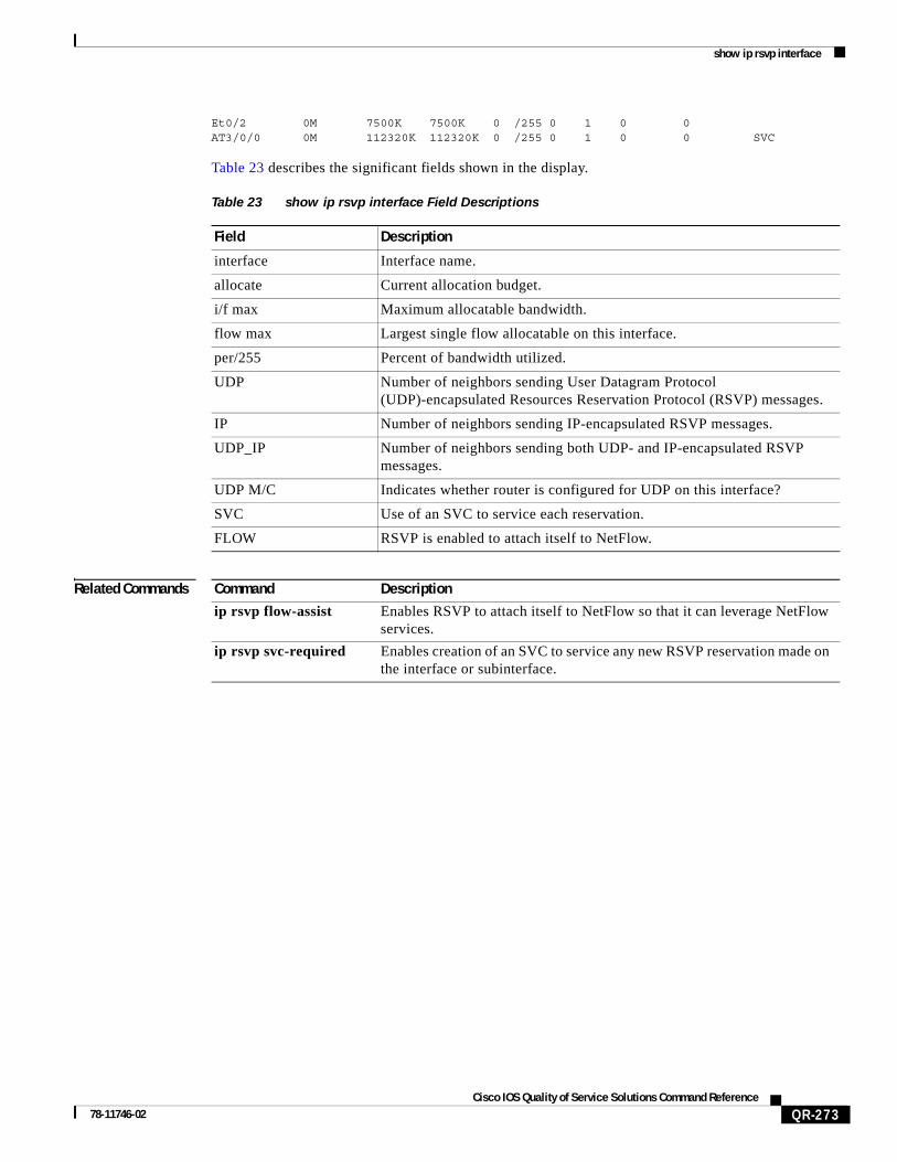
Et0/2 0M 7500K 7500K 0 /255 0 1 0 0 AT3/0/0 0M 112320K 112320K 0 /255 0 1 0 0 SVC
Table 23 describes the significant fields shown in the display.
Related Commands
Table 23 show ip rsvp interface Field Descriptions
Field Description
interface Interface name.
allocate Current allocation budget.
i/f max Maximum allocatable bandwidth.
flow max Largest single flow allocatable on this interface.
per/255 Percent of bandwidth utilized.
UDP Number of neighbors sending User Datagram Protocol (UDP)-encapsulated Resources Reservation Protocol (RSVP) messages.
IP Number of neighbors sending IP-encapsulated RSVP messages.
UDP_IP Number of neighbors sending both UDP- and IP-encapsulated RSVP messages.
UDP M/C Indicates whether router is configured for UDP on this interface?
SVC Use of an SVC to service each reservation.
FLOW RSVP is enabled to attach itself to NetFlow.
Command Description
ip rsvp flow-assist Enables RSVP to attach itself to NetFlow so that it can leverage NetFlow services.
ip rsvp svc-required Enables creation of an SVC to service any new RSVP reservation made on the interface or subinterface.

show ip rsvp neighbor
QR-274Cisco IOS Quality of Service Solutions Command Reference
78-11746-02
show ip rsvp neighborTo display current Resource Reservation Protocol (RSVP) neighbors, use the show ip rsvp neighbor EXEC command.
show ip rsvp neighbor [interface-type interface-number]
Syntax Description
Command Modes EXEC
Command History
Usage Guidelines Use this command to show the current RSVP neighbors and identify if the neighbor is using IP, User Datagram Protocol (UDP), or RSVP encapsulation for a specified interface or all interfaces.
Examples The following is sample output from the show ip rsvp neighbor command:
Router# show ip rsvp neighbor
Interface Neighbor EncapsulationSe1 132.240.1.49 RSVP
Table 24 describes significant fields shown in the display.
interface-type (Optional) Specifies the type of the interface.
interface-number (Optional) Specifies the number of the interface.
Release Modification
11.2 This command was introduced.
Table 24 show ip rsvp neighbor Field Descriptions
Field Description
Interface Interface name.
Neighbor IP address of the RSVP neighbor.
Encapsulation The type of encapsulation the neighbor is using: IP, UDP, or RSVP.

show ip rsvp policy cops
QR-275Cisco IOS Quality of Service Solutions Command Reference
78-11746-02
show ip rsvp policy copsTo display the policy server addresses, access control list (ACL) IDs, and current state of the router-server connection, use the show ip rsvp policy cops command.
show ip rsvp policy cops [acl]
Syntax Description
Defaults This command has no default behavior or values.
Command Modes EXEC
Command History
Usage Guidelines If you omit the final keyword of this command (cops), the display reports only on the ACLs and their connection status. This kind of display is shown in the second example in the “Examples” section.
If the server connection has recently broken, this command also displays the reconnection attempt interval.
Examples The following example shows the full display, using the full command:
Router# show ip rsvp policy cops
COPS/RSVP entry. ACLs: 40 60 PDPs: 161.44.135.172 Current state: ConnectedCurrently connected to PDP 161.44.135.172, port 0
The following example shows the ID for the configured ACLs and their connection status, using the shortened command:
Router# show ip rsvp policy
Local policy: Currently unsupportedCOPS:
ACLs: 40 60 . State: CONNECTED. ACLs: 40 160 . State: CONNECTING.
[acl] (Optional) The ACLs whose sessions are governed by Common Open Policy Service (COPS). An ACL can be a number from 1 to 199.
Release Modification
12.1(1)T This command was introduced.

show ip rsvp policy cops
QR-276Cisco IOS Quality of Service Solutions Command Reference
78-11746-02
Related Commands Command Description
show cops servers Displays the IP address and connection status of the policy servers for which the router is configured.

show ip rsvp request
QR-277Cisco IOS Quality of Service Solutions Command Reference
78-11746-02
show ip rsvp requestTo display Resource Reservation Protocol (RSVP)-related request information being requested upstream, use the show ip rsvp request EXEC command.
show ip rsvp request [ip-address][detail]
Syntax Description
Command Modes EXEC
Command History
Usage Guidelines Use this command to show the RSVP reservations currently being requested upstream for a specified interface or all interfaces. The received reservations may differ from requests because of aggregated or refused reservations.
Examples The following is sample output from the show ip rsvp request command:
Router# show ip rsvp request
To From Pro DPort Sport Next Hop I/F Fi Serv132.240.1.49 132.240.4.53 1 0 0 132.240.3.53 Et1 FF LOAD
Table 25 describes the significant fields shown in the display.
ip-address (Optional) IP or group address of the requestor.
detail (Optional) Specifies additional request information.
Release Modification
11.2 This command was introduced.
Table 25 show ip rsvp request Field Descriptions
Field Description
To IP address of the receiver.
From IP address of the sender.
Pro Protocol code. Code 1 indicates Internet Control Message Protocol (ICMP).
DPort Destination port number.
Sport Source port number.
Next Hop IP address of the next hop.
I/F Interface of the next hop.
Fi Filter (Wild Card Filter, Shared Explicit, or Fixed Filter).
Serv Service (value can be rate or load).
show ip rsvp reservation
QR-278Cisco IOS Quality of Service Solutions Command Reference
78-11746-02
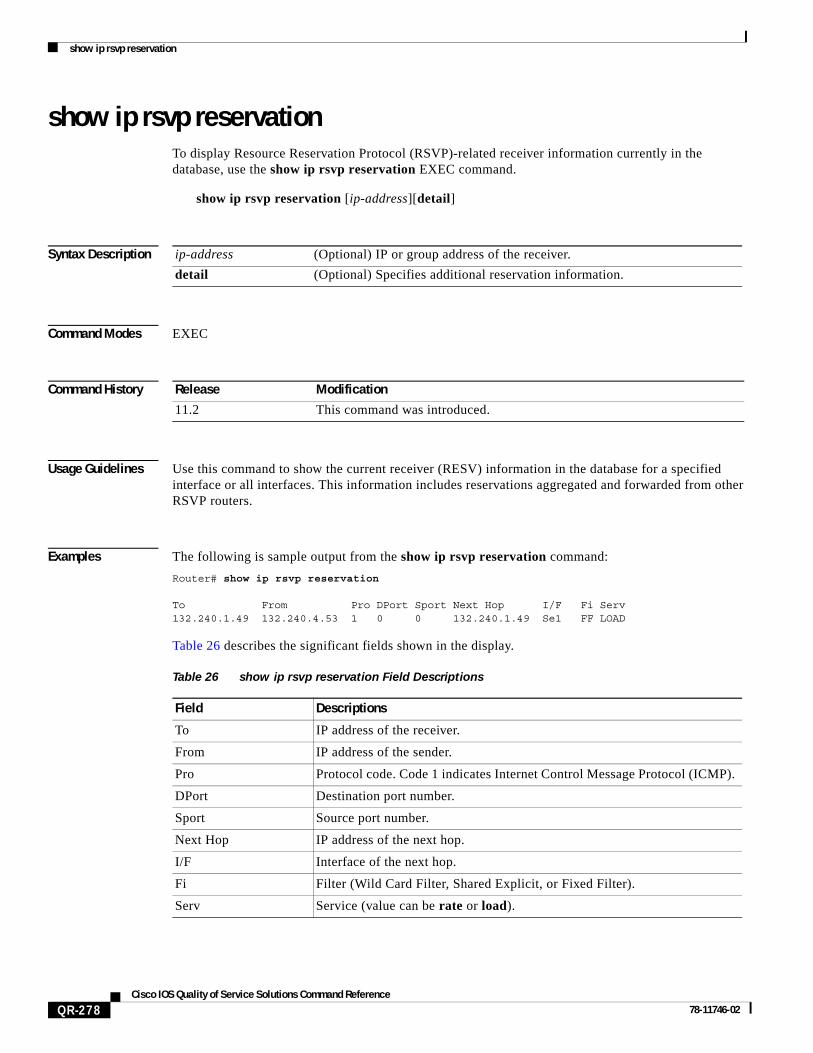
show ip rsvp reservationTo display Resource Reservation Protocol (RSVP)-related receiver information currently in the database, use the show ip rsvp reservation EXEC command.
show ip rsvp reservation [ip-address][detail]
Syntax Description
Command Modes EXEC
Command History
Usage Guidelines Use this command to show the current receiver (RESV) information in the database for a specified interface or all interfaces. This information includes reservations aggregated and forwarded from other RSVP routers.
Examples The following is sample output from the show ip rsvp reservation command:
Router# show ip rsvp reservation
To From Pro DPort Sport Next Hop I/F Fi Serv132.240.1.49 132.240.4.53 1 0 0 132.240.1.49 Se1 FF LOAD
Table 26 describes the significant fields shown in the display.
ip-address (Optional) IP or group address of the receiver.
detail (Optional) Specifies additional reservation information.
Release Modification
11.2 This command was introduced.
Table 26 show ip rsvp reservation Field Descriptions
Field Descriptions
To IP address of the receiver.
From IP address of the sender.
Pro Protocol code. Code 1 indicates Internet Control Message Protocol (ICMP).
DPort Destination port number.
Sport Source port number.
Next Hop IP address of the next hop.
I/F Interface of the next hop.
Fi Filter (Wild Card Filter, Shared Explicit, or Fixed Filter).
Serv Service (value can be rate or load).
show ip rsvp sbm
QR-279Cisco IOS Quality of Service Solutions Command Reference
78-11746-02
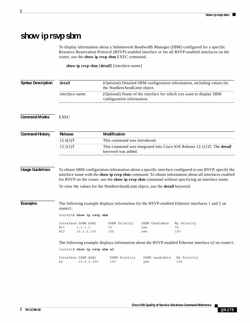
show ip rsvp sbmTo display information about a Subnetwork Bandwidth Manager (SBM) configured for a specific Resource Reservation Protocol (RSVP)-enabled interface or for all RSVP-enabled interfaces on the router, use the show ip rsvp sbm EXEC command.
show ip rsvp sbm [detail] [interface-name]
Syntax Description
Command Modes EXEC
Command History
Usage Guidelines To obtain SBM configuration information about a specific interface configured to use RSVP, specify the interface name with the show ip rsvp sbm command. To obtain information about all interfaces enabled for RSVP on the router, use the show ip rsvp sbm command without specifying an interface name.
To view the values for the NonResvSendLimit object, use the detail keyword.
Examples The following example displays information for the RSVP-enabled Ethernet interfaces 1 and 2 on router1:
router1# show ip rsvp sbm
Interface DSBM Addr DSBM Priority DSBM Candidate My PriorityEt1 1.1.1.1 70 yes 70Et2 10.2.2.150 100 yes 100
The following example displays information about the RSVP-enabled Ethernet interface e2 on router1:
router1# show ip rsvp sbm e2
Interface DSBM Addr DSBM Priority DSBM candidate My Prioritye2 10.2.2.150 100 yes 100
detail (Optional) Detailed SBM configuration information, including values for the NonResvSendLimit object.
interface-name (Optional) Name of the interface for which you want to display SBM configuration information.
Release Modification
12.0(5)T This command was introduced.
12.1(1)T This command was integrated into Cisco IOS Release 12.1(1)T. The detail keyword was added.
show ip rsvp sbm
QR-280Cisco IOS Quality of Service Solutions Command Reference
78-11746-02
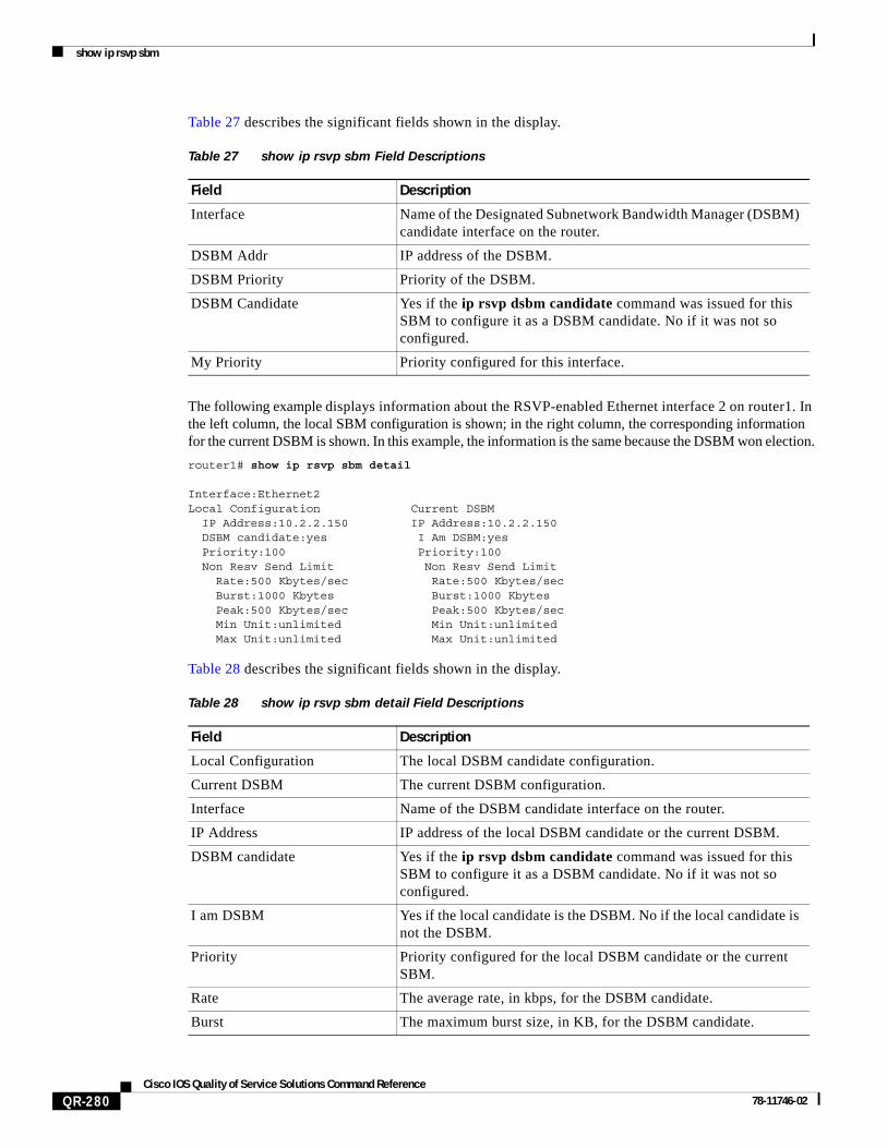
Table 27 describes the significant fields shown in the display.
The following example displays information about the RSVP-enabled Ethernet interface 2 on router1. In the left column, the local SBM configuration is shown; in the right column, the corresponding information for the current DSBM is shown. In this example, the information is the same because the DSBM won election.
router1# show ip rsvp sbm detail
Interface:Ethernet2Local Configuration Current DSBM IP Address:10.2.2.150 IP Address:10.2.2.150 DSBM candidate:yes I Am DSBM:yes Priority:100 Priority:100 Non Resv Send Limit Non Resv Send Limit Rate:500 Kbytes/sec Rate:500 Kbytes/sec Burst:1000 Kbytes Burst:1000 Kbytes Peak:500 Kbytes/sec Peak:500 Kbytes/sec Min Unit:unlimited Min Unit:unlimited Max Unit:unlimited Max Unit:unlimited
Table 28 describes the significant fields shown in the display.
Table 27 show ip rsvp sbm Field Descriptions
Field Description
Interface Name of the Designated Subnetwork Bandwidth Manager (DSBM) candidate interface on the router.
DSBM Addr IP address of the DSBM.
DSBM Priority Priority of the DSBM.
DSBM Candidate Yes if the ip rsvp dsbm candidate command was issued for this SBM to configure it as a DSBM candidate. No if it was not so configured.
My Priority Priority configured for this interface.
Table 28 show ip rsvp sbm detail Field Descriptions
Field Description
Local Configuration The local DSBM candidate configuration.
Current DSBM The current DSBM configuration.
Interface Name of the DSBM candidate interface on the router.
IP Address IP address of the local DSBM candidate or the current DSBM.
DSBM candidate Yes if the ip rsvp dsbm candidate command was issued for this SBM to configure it as a DSBM candidate. No if it was not so configured.
I am DSBM Yes if the local candidate is the DSBM. No if the local candidate is not the DSBM.
Priority Priority configured for the local DSBM candidate or the current SBM.
Rate The average rate, in kbps, for the DSBM candidate.
Burst The maximum burst size, in KB, for the DSBM candidate.
show ip rsvp sbm
QR-281Cisco IOS Quality of Service Solutions Command Reference
78-11746-02
Related Commands
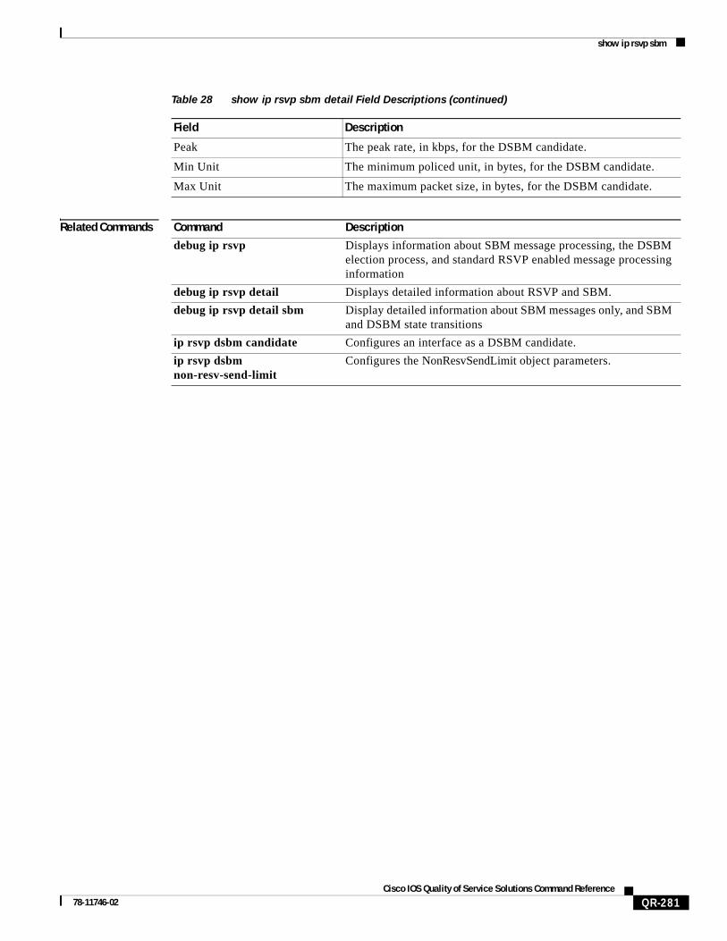
Peak The peak rate, in kbps, for the DSBM candidate.
Min Unit The minimum policed unit, in bytes, for the DSBM candidate.
Max Unit The maximum packet size, in bytes, for the DSBM candidate.
Table 28 show ip rsvp sbm detail Field Descriptions (continued)
Field Description
Command Description
debug ip rsvp Displays information about SBM message processing, the DSBM election process, and standard RSVP enabled message processing information
debug ip rsvp detail Displays detailed information about RSVP and SBM.
debug ip rsvp detail sbm Display detailed information about SBM messages only, and SBM and DSBM state transitions
ip rsvp dsbm candidate Configures an interface as a DSBM candidate.
ip rsvp dsbm non-resv-send-limit
Configures the NonResvSendLimit object parameters.
show ip rsvp sender
QR-282Cisco IOS Quality of Service Solutions Command Reference
78-11746-02
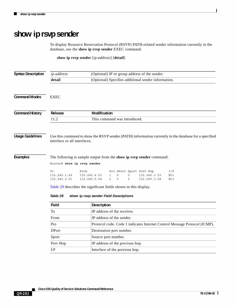
show ip rsvp senderTo display Resource Reservation Protocol (RSVP) PATH-related sender information currently in the database, use the show ip rsvp sender EXEC command.
show ip rsvp sender [ip-address] [detail]
Syntax Description
Command Modes EXEC
Command History
Usage Guidelines Use this command to show the RSVP sender (PATH) information currently in the database for a specified interface or all interfaces.
Examples The following is sample output from the show ip rsvp sender command:
Router# show ip rsvp sender
To From Pro DPort Sport Prev Hop I/F132.240.1.49 132.240.4.53 1 0 0 132.240.3.53 Et1132.240.2.51 132.240.5.54 1 0 0 132.240.3.54 Et1
Table 29 describes the significant fields shown in this display.
ip-address (Optional) IP or group address of the sender.
detail (Optional) Specifies additional sender information.
Release Modification
11.2 This command was introduced.
Table 29 show ip rsvp sender Field Descriptions
Field Description
To IP address of the receiver.
From IP address of the sender.
Pro Protocol code. Code 1 indicates Internet Control Message Protocol (ICMP).
DPort Destination port number.
Sport Source port number.
Prev Hop IP address of the previous hop.
I/F Interface of the previous hop.

show policy-map
QR-283Cisco IOS Quality of Service Solutions Command Reference
78-11746-02
show policy-mapTo display the configuration of all classes for a specified service policy map or all classes for all existing policy maps, use the show policy-map EXEC or privileged EXEC command.
show policy-map [policy-map]
Syntax Description
Defaults All existing policy map configurations are displayed.
Command Modes EXEC or privileged EXEC
Command History
Usage Guidelines The show policy-map command displays the configuration of a service policy map created using the policy-map command. You can use the show policy-map command to display all class configurations comprising any existing service policy map, whether or not that service policy map has been attached to an interface.
Examples The following example displays the contents of the service policy map called po1:
Router# show policy-map po1
Policy Map po1 Weighted Fair Queueing Class class1 Bandwidth 937 (kbps) Max thresh 64 (packets) Class class2 Bandwidth 937 (kbps) Max thresh 64 (packets) Class class3 Bandwidth 937 (kbps) Max thresh 64 (packets) Class class4 Bandwidth 937 (kbps) Max thresh 64 (packets) Class class5 Bandwidth 937 (kbps) Max thresh 64 (packets) Class class6 Bandwidth 937 (kbps) Max thresh 64 (packets)
policy-map (Optional) The name of the service policy map whose complete configuration is to be displayed. The name can be a maximum of 40 characters.
Release Modification
12.0(5)T This command was introduced.
12.0(5)XE This command was integrated into Cisco IOS Release 12.0(5)XE.
12.0(7)S This command was integrated into Cisco IOS Release 12.0(7)S.
12.1(1)E This command was integrated into Cisco IOS Release 12.1(1)E.

show policy-map
QR-284Cisco IOS Quality of Service Solutions Command Reference
78-11746-02
Class class7 Bandwidth 937 (kbps) Max thresh 64 (packets) Class class8 Bandwidth 937 (kbps) Max thresh 64 (packets)
The following example displays the contents of all policy maps on the router:
Router# show policy-map
Policy Map poH1 Weighted Fair Queueing Class class1 Bandwidth 937 (kbps) Max thresh 64 (packets) Class class2 Bandwidth 937 (kbps) Max thresh 64 (packets) Class class3 Bandwidth 937 (kbps) Max thresh 64 (packets) Class class4 Bandwidth 937 (kbps) Max thresh 64 (packets) Class class5 Bandwidth 937 (kbps) Max thresh 64 (packets) Class class6 Bandwidth 937 (kbps) Max thresh 64 (packets) Class class7 Bandwidth 937 (kbps) Max thresh 64 (packets) Class class8 Bandwidth 937 (kbps) Max thresh 64 (packets)Policy Map policy2 Weighted Fair Queueing Class class1 Bandwidth 300 (kbps) Max thresh 64 (packets) Class class2 Bandwidth 300 (kbps) Max thresh 64 (packets) Class class3 Bandwidth 300 (kbps) Max thresh 64 (packets) Class class4 Bandwidth 300 (kbps) Max thresh 64 (packets) Class class5 Bandwidth 300 (kbps) Max thresh 64 (packets) Class class6 Bandwidth 300 (kbps) Max thresh 64 (packets)
Related Commands Command Description
policy-map Creates or modifies a policy map that can be attached to one or more interfaces to specify a service policy.
show policy-map class Displays the configuration for the specified class of the specified policy map.
show policy-map interface Displays the configuration of all classes configured for all service policies on the specified interface or displays the classes for the service policy for a specific PVC on the interface.

show policy-map class
QR-285Cisco IOS Quality of Service Solutions Command Reference
78-11746-02
show policy-map classTo display the configuration for the specified class of the specified policy map, use the show policy-map class EXEC or privileged EXEC command.
show policy-map policy-map class class-name
Syntax Description
Defaults This command has no default behavior or values.
Command Modes EXEC or privileged EXEC
Command History
Usage Guidelines You can use the show policy-map class command to display any single class configuration for any service policy map, whether or not the specified service policy map has been attached to an interface.
Examples The following example displays configurations for the class called class7 that belongs to the policy map called po1:
Router# show policy-map po1 class class7
Class class7 Bandwidth 937 (kbps) Max Thresh 64 (packets)
Related Commands
policy-map The name of a policy map that contains the class configuration to be displayed.
class-name The name of the class whose configuration is to be displayed.
Release Modification
12.0(5)T This command was introduced.
12.0(5)XE This command was integrated into Cisco IOS Release 12.0(5)XE.
12.0(7)S This command was integrated into Cisco IOS Release 12.0(7)S.
12.1(1)E This command was integrated into Cisco IOS Release 12.1(1)E.
Command Description
show policy-map Displays the configuration of all classes for a specified service policy map or all classes for all existing policy maps.
show policy-map interface
Displays the configuration of all classes configured for all service policies on the specified interface or displays the classes for the service policy for a specific PVC on the interface.

show policy-map interface
QR-286Cisco IOS Quality of Service Solutions Command Reference
78-11746-02
show policy-map interfaceTo display the configuration of all classes configured for all service policies on the specified interface or to display the classes for the service policy for a specific permanent virtual circuit (PVC) on the interface, use the show policy-map interface EXEC or privileged EXEC command.
show policy-map interface interface-name [vc [vpi/] vci][dlci dlci] [input | output]
Syntax Description
Defaults This command has no default behavior or values.
Command Modes EXEC or privileged EXEC
interface-name Name of the interface or subinterface whose policy configuration is to be displayed.
vc (Optional) For ATM interfaces only, shows the policy configuration for a specified PVC. The name can be up to 16 characters long.
vpi/ (Optional) ATM network virtual path identifier (VPI) for this PVC. The absence of the “/” and a vpi value defaults the vpi value to 0.
On the Cisco 7200 and 7500 series routers, this value ranges from 0 to 255.
The vpi and vci arguments cannot both be set to 0; if one is 0, the other cannot be 0.
If this value is omitted, information for all virtual circuits (VCs) on the specified ATM interface or subinterface is displayed.
vci (Optional) ATM network virtual channel identifier (VCI) for this PVC. This value ranges from 0 to 1 less than the maximum value set for this interface by the atm vc-per-vp command. Typically, lower values 0 to 31 are reserved for specific traffic (F4 Operation, Administration, and Maintenance (OAM), switched virtual circuit (SVC) signalling, Integrated Local Management Interface (ILMI), and so on) and should not be used.
The VCI is a 16-bit field in the header of the ATM cell. The VCI value is unique only on a single link, not throughout the ATM network, because it has local significance only.
The vpi and vci arguments cannot both be set to 0; if one is 0, the other cannot be 0.
dlci (Optional) Indicates that a specific PVC for which policy configuration will be displayed.
dlci (Optional) A specific data-link connection identifier (DLCI) number used on the interface. Policy configuration for the corresponding PVC will be displayed when a DLCI is specified.
input (Optional) Indicates that the statistics for the attached input policy will be displayed.
output (Optional) Indicates that the statistics for the attached output policy will be displayed.
show policy-map interface
QR-287Cisco IOS Quality of Service Solutions Command Reference
78-11746-02
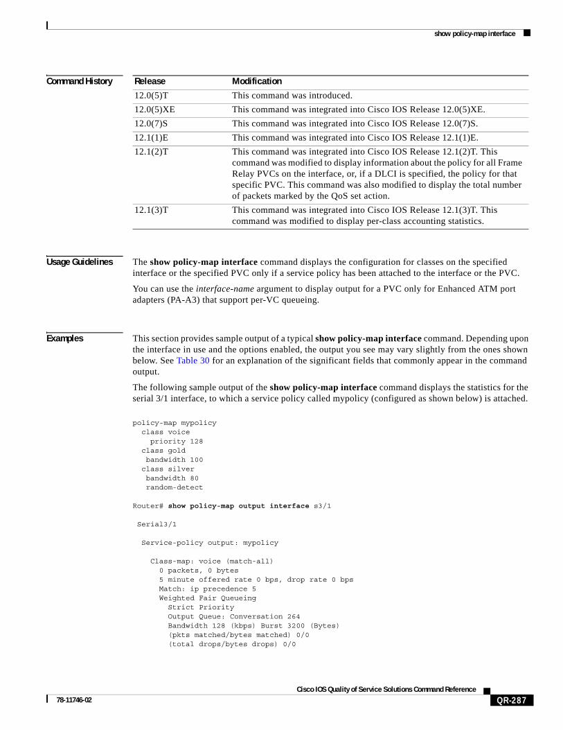
Command History
Usage Guidelines The show policy-map interface command displays the configuration for classes on the specified interface or the specified PVC only if a service policy has been attached to the interface or the PVC.
You can use the interface-name argument to display output for a PVC only for Enhanced ATM port adapters (PA-A3) that support per-VC queueing.
Examples This section provides sample output of a typical show policy-map interface command. Depending upon the interface in use and the options enabled, the output you see may vary slightly from the ones shown below. See Table 30 for an explanation of the significant fields that commonly appear in the command output.
The following sample output of the show policy-map interface command displays the statistics for the serial 3/1 interface, to which a service policy called mypolicy (configured as shown below) is attached.
policy-map mypolicy class voice priority 128 class gold bandwidth 100 class silver bandwidth 80 random-detect
Router# show policy-map output interface s3/1
Serial3/1
Service-policy output: mypolicy
Class-map: voice (match-all) 0 packets, 0 bytes 5 minute offered rate 0 bps, drop rate 0 bps Match: ip precedence 5 Weighted Fair Queueing Strict Priority Output Queue: Conversation 264 Bandwidth 128 (kbps) Burst 3200 (Bytes) (pkts matched/bytes matched) 0/0 (total drops/bytes drops) 0/0
Release Modification
12.0(5)T This command was introduced.
12.0(5)XE This command was integrated into Cisco IOS Release 12.0(5)XE.
12.0(7)S This command was integrated into Cisco IOS Release 12.0(7)S.
12.1(1)E This command was integrated into Cisco IOS Release 12.1(1)E.
12.1(2)T This command was integrated into Cisco IOS Release 12.1(2)T. This command was modified to display information about the policy for all Frame Relay PVCs on the interface, or, if a DLCI is specified, the policy for that specific PVC. This command was also modified to display the total number of packets marked by the QoS set action.
12.1(3)T This command was integrated into Cisco IOS Release 12.1(3)T. This command was modified to display per-class accounting statistics.
show policy-map interface
QR-288Cisco IOS Quality of Service Solutions Command Reference
78-11746-02
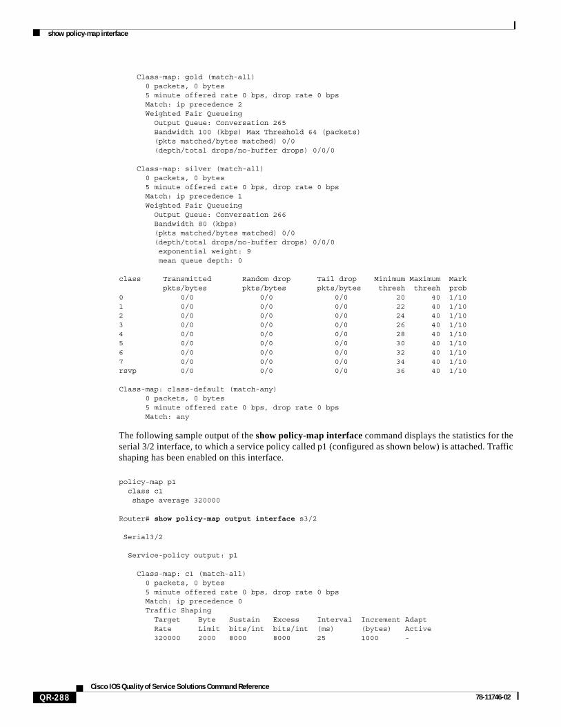
Class-map: gold (match-all) 0 packets, 0 bytes 5 minute offered rate 0 bps, drop rate 0 bps Match: ip precedence 2 Weighted Fair Queueing Output Queue: Conversation 265 Bandwidth 100 (kbps) Max Threshold 64 (packets) (pkts matched/bytes matched) 0/0 (depth/total drops/no-buffer drops) 0/0/0
Class-map: silver (match-all) 0 packets, 0 bytes 5 minute offered rate 0 bps, drop rate 0 bps Match: ip precedence 1 Weighted Fair Queueing Output Queue: Conversation 266 Bandwidth 80 (kbps) (pkts matched/bytes matched) 0/0 (depth/total drops/no-buffer drops) 0/0/0 exponential weight: 9 mean queue depth: 0
class Transmitted Random drop Tail drop Minimum Maximum Mark pkts/bytes pkts/bytes pkts/bytes thresh thresh prob0 0/0 0/0 0/0 20 40 1/101 0/0 0/0 0/0 22 40 1/102 0/0 0/0 0/0 24 40 1/103 0/0 0/0 0/0 26 40 1/104 0/0 0/0 0/0 28 40 1/105 0/0 0/0 0/0 30 40 1/106 0/0 0/0 0/0 32 40 1/107 0/0 0/0 0/0 34 40 1/10rsvp 0/0 0/0 0/0 36 40 1/10
Class-map: class-default (match-any) 0 packets, 0 bytes 5 minute offered rate 0 bps, drop rate 0 bps Match: any
The following sample output of the show policy-map interface command displays the statistics for the serial 3/2 interface, to which a service policy called p1 (configured as shown below) is attached. Traffic shaping has been enabled on this interface.
policy-map p1 class c1 shape average 320000
Router# show policy-map output interface s3/2
Serial3/2
Service-policy output: p1
Class-map: c1 (match-all) 0 packets, 0 bytes 5 minute offered rate 0 bps, drop rate 0 bps Match: ip precedence 0 Traffic Shaping Target Byte Sustain Excess Interval Increment Adapt Rate Limit bits/int bits/int (ms) (bytes) Active 320000 2000 8000 8000 25 1000 -

show policy-map interface
QR-289Cisco IOS Quality of Service Solutions Command Reference
78-11746-02
Queue Packets Bytes Packets Bytes Shaping Depth Delayed Delayed Active 0 0 0 0 0 no
Class-map: class-default (match-any) 0 packets, 0 bytes 5 minute offered rate 0 bps, drop rate 0 bps Match: any
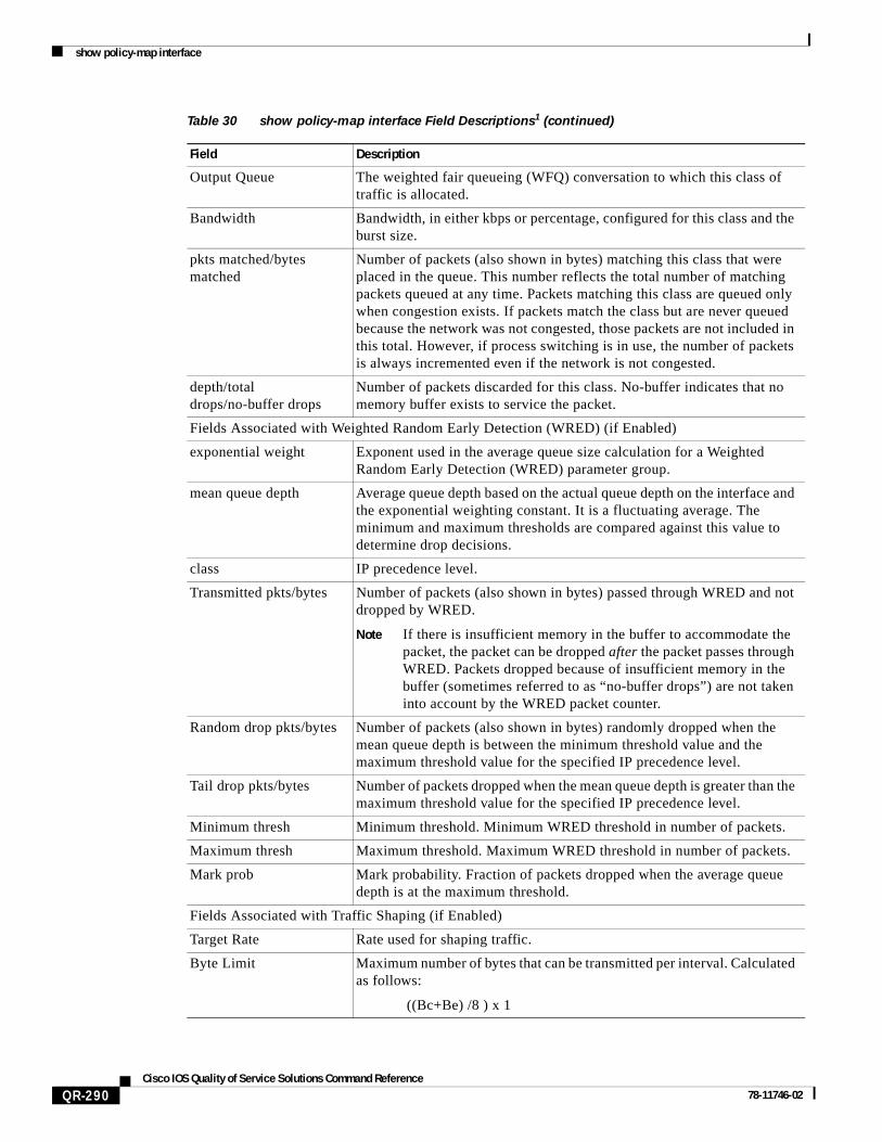
Table 30 describes the significant fields shown in the displays. The fields in the table are grouped according to the relevant QoS feature.
Table 30 show policy-map interface Field Descriptions1
Field Description
Fields Associated with Classes or Service Policies
Service-policy output Name of the output service policy applied to the specified interface or VC.
Class-map Class of traffic being displayed. Output is displayed for each configured class in the policy. The choice for implementing class matches (for example, match-all or match-any) can also appear next to the traffic class.
packets and bytes Number of packets (also shown in bytes) identified as belonging to the class of traffic being displayed.
offered rate Rate, in kbps, of packets coming in to the class.
Note If the packets are compressed over an outgoing interface, the improved packet rate achieved by packet compression is not reflected in the offered rate. Also, if the packets are classified before they enter a combination of tunnels (for example, a generic routing encapsulation (GRE) tunnel and an IP Security (IPSec) tunnel), the offered rate does not include all the extra overhead associated with tunnel encapsulation in general. Depending on the configuration, the offered rate may include no overhead, may include the overhead for only one tunnel encapsulation, or may include the overhead for all tunnel encapsulations. In most of the GRE and IPSec tunnel configurations, the offered rate includes the overhead for GRE tunnel encapsulation only.
drop rate Rate, in kbps, at which packets are dropped from the class. The drop rate is calculated by subtracting the number of successfully transmitted packets from the offered rate.
Note In distributed architecture platforms (such as the C7500), the value of the transfer rate, calculated as the difference between the offered rate and the drop rate counters, can sporadically deviate from the average by up to 20 percent or more. This can occur while no corresponding burst is registered by independent traffic analyser equipment.
Match Match criteria specified for the class of traffic. Choices include criteria such as IP precedence, IP DSCP value, MPLS experimental value, access groups, and QoS groups. For more information about the variety of match criteria options available, refer to the chapter “Configuring the Modular Quality of Service Command-Line Interface” in the Cisco IOS Quality of Service Solutions Configuration Guide, Release 12.2.
Fields Associated with Queueing (if Enabled)
show policy-map interface
QR-290Cisco IOS Quality of Service Solutions Command Reference
78-11746-02
Output Queue The weighted fair queueing (WFQ) conversation to which this class of traffic is allocated.
Bandwidth Bandwidth, in either kbps or percentage, configured for this class and the burst size.
pkts matched/bytes matched
Number of packets (also shown in bytes) matching this class that were placed in the queue. This number reflects the total number of matching packets queued at any time. Packets matching this class are queued only when congestion exists. If packets match the class but are never queued because the network was not congested, those packets are not included in this total. However, if process switching is in use, the number of packets is always incremented even if the network is not congested.
depth/total drops/no-buffer drops
Number of packets discarded for this class. No-buffer indicates that no memory buffer exists to service the packet.
Fields Associated with Weighted Random Early Detection (WRED) (if Enabled)
exponential weight Exponent used in the average queue size calculation for a Weighted Random Early Detection (WRED) parameter group.
mean queue depth Average queue depth based on the actual queue depth on the interface and the exponential weighting constant. It is a fluctuating average. The minimum and maximum thresholds are compared against this value to determine drop decisions.
class IP precedence level.
Transmitted pkts/bytes Number of packets (also shown in bytes) passed through WRED and not dropped by WRED.
Note If there is insufficient memory in the buffer to accommodate the packet, the packet can be dropped after the packet passes through WRED. Packets dropped because of insufficient memory in the buffer (sometimes referred to as “no-buffer drops”) are not taken into account by the WRED packet counter.
Random drop pkts/bytes Number of packets (also shown in bytes) randomly dropped when the mean queue depth is between the minimum threshold value and the maximum threshold value for the specified IP precedence level.
Tail drop pkts/bytes Number of packets dropped when the mean queue depth is greater than the maximum threshold value for the specified IP precedence level.
Minimum thresh Minimum threshold. Minimum WRED threshold in number of packets.
Maximum thresh Maximum threshold. Maximum WRED threshold in number of packets.
Mark prob Mark probability. Fraction of packets dropped when the average queue depth is at the maximum threshold.
Fields Associated with Traffic Shaping (if Enabled)
Target Rate Rate used for shaping traffic.
Byte Limit Maximum number of bytes that can be transmitted per interval. Calculated as follows:
((Bc+Be) /8 ) x 1
Table 30 show policy-map interface Field Descriptions1 (continued)
Field Description

show policy-map interface
QR-291Cisco IOS Quality of Service Solutions Command Reference
78-11746-02
Related Commands
Sustain bits/int Committed burst (Bc) rate.
Excess bits/int Excess burst (Be) rate.
Interval (ms) Time interval value in milliseconds (ms).
Increment (bytes) Number of credits (in bytes) received in the token bucket of the traffic shaper during each time interval.
Queue Depth Current queue depth of the traffic shaper.
Packets Total number of packets that have entered the traffic shaper system.
Bytes Total number of bytes that have entered the traffic shaper system.
Packets Delayed Total number of packets delayed in the queue of the traffic shaper before being transmitted.
Bytes Delayed Total number of bytes delayed in the queue of the traffic shaper before being transmitted.
Shaping Active Indicates whether the traffic shaper is active. For example, if a traffic shaper is active, and the traffic being sent exceeds the traffic shaping rate, a “yes” appears in this field.
1. A number in parentheses may appear next to the service-policy output name, class-map name, and match criteria information. The number is for Cisco internal use only and can be disregarded.
Table 30 show policy-map interface Field Descriptions1 (continued)
Field Description
Command Description
show frame-relay pvc Displays statistics about PVCs for Frame Relay interfaces.
show policy-map Displays the configuration of all classes for a specified service policy map or all classes for all existing policy maps.
show policy-map class Displays the configuration for the specified class of the specified policy map.

show qdm status
QR-292Cisco IOS Quality of Service Solutions Command Reference
78-11746-02
show qdm statusTo view the status of the Quality of Service Device Manager (QDM) clients connected to the router, use the show qdm status EXEC command.
show qdm status
Syntax Description This command has no arguments or keywords.
Defaults This command has no default behavior or values.
Command Modes EXEC
Command History
Usage Guidelines Use the show qdm status command to obtain the following information:
• Number of connected QDM clients
• Client IDs of the connected QDM clients
• Version of the QDM client software
• IP addresses of the connected QDM clients
Examples The following example illustrates the show qdm status output when two QDM clients are connected to the router:
Router# show qdm status
Number of QDM Clients :2QDM Client v1.0(0.13)-System_1 @ 172.16.0.0 (id:30) connected since 09:22:36 UTC Wed Mar 15 2000QDM Client v1.0(0.12)-System_2 @ 172.31.255.255 (id:29) connected since 17:10:23 UTC Tue Mar 14 2000
Related Commands
Release Modification
Release 12.1(1)E This command was introduced.
Release 12.1(5)T This command was integrated into Cisco IOS Release 12.1(5)T.
Command Description
disconnect qdm Disconnects a QDM client.