shubham ppt on ospf and framerelay
TRANSCRIPT
10/22/2013 1
HIMALAYAN INSTITUTE OF TECHNOLOGY & MANAGEMENT
10/22/2013 2
PRESENT & DESIGN BY:-
SHUBHAM KATIYARB.TECH 6TH SEM.ROLL NO. :-1046510033
NETWORKING TECHNIQUEFRAME RELAY
& OSPF
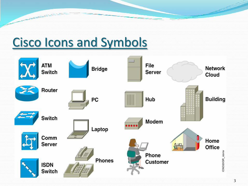
Cisco Icons and Symbols
3
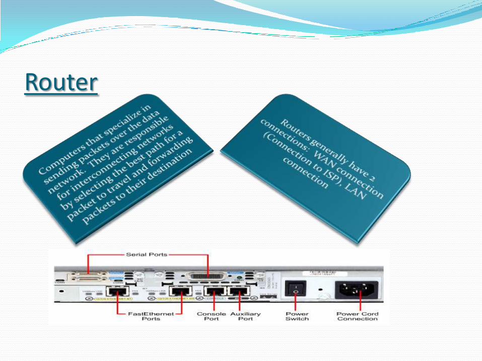
Router
Network Switches..A network switch is a small hardware device that joinsmultiple computers together within one Local AreaNetwork(LAN). Technically switches operate at Data-linkLayer. These are almost like HUBS. But unlike HUBSnetwork switches are capable of inspecting data as it isrecieved, determining the source and destination device ofeach packet, and forwarding them appropriately.
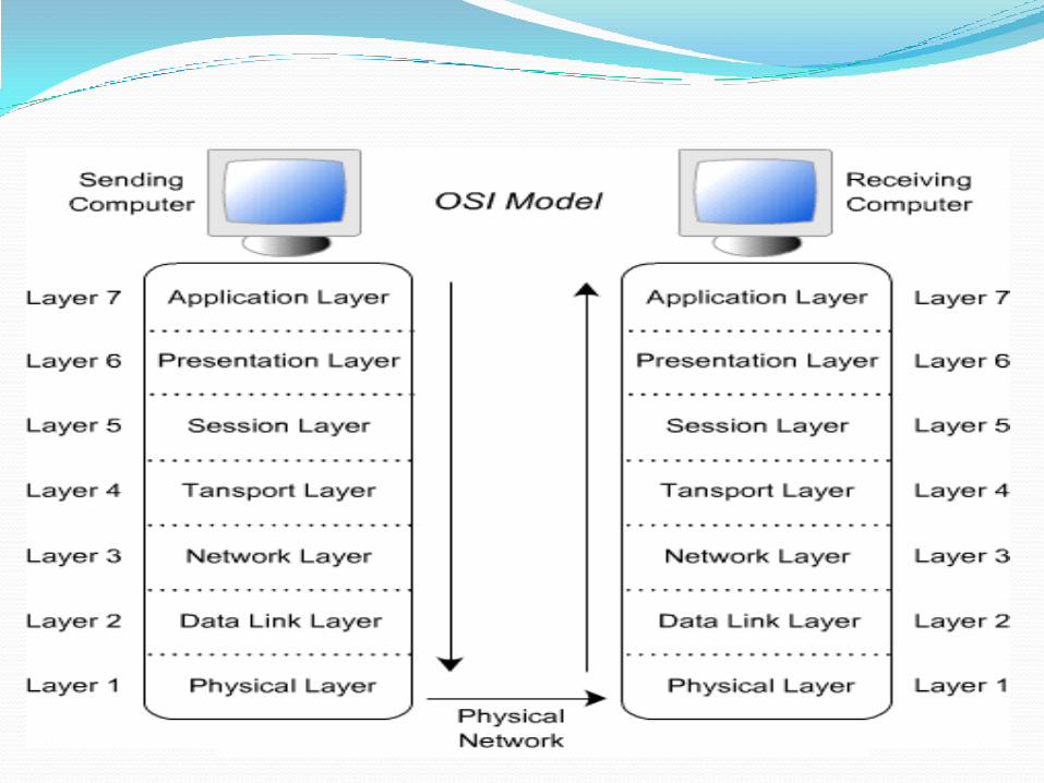
OSI Model OSI model consists of seven layers and provides
standards for computer communication
Physical layer is responsible for actual transmission of bits over the medium
Data Link layer is responsible for node to node delivery of frames
Network layer is responsible for end to end delivery of packets, and routing
OSI Model Transport layer is responsible for end to end delivery of
the entire message
Session layer is responsible for establishing, managing and terminating sessions
Presentation layer is responsible for translation, encryption and data compression
Application layer is responsible for providing access to the network
FRAME RELAYFrame relay is a packet switched connection oriented
WAN service .It operates at the Data link layer of OSI Model.
Frame carry data between user devices called Data terminal equipment (DTE) and Data communication equipment ( DCE) at the edge of the WAN.
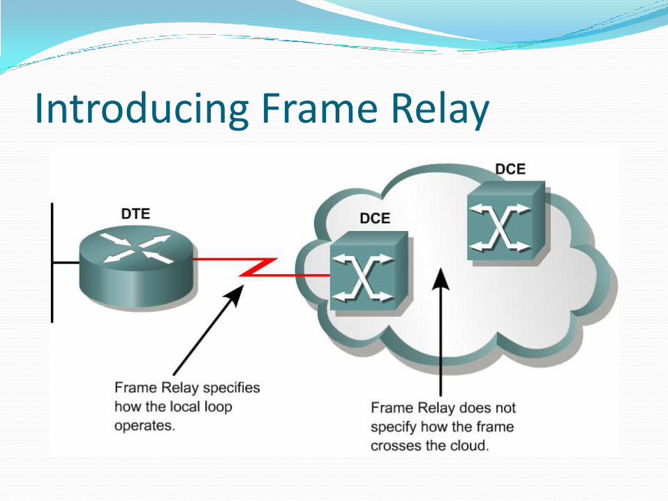
Introducing Frame Relay
Frame relay is a Scalable WAN solution that is often used as an alternative to leased line when leased line prove to be cost prohibitive.
Frame relay is a non broadcast multi access ( NBMA) medium which means that broadcast traffic is not allowed to traverse Frame relay traffic.
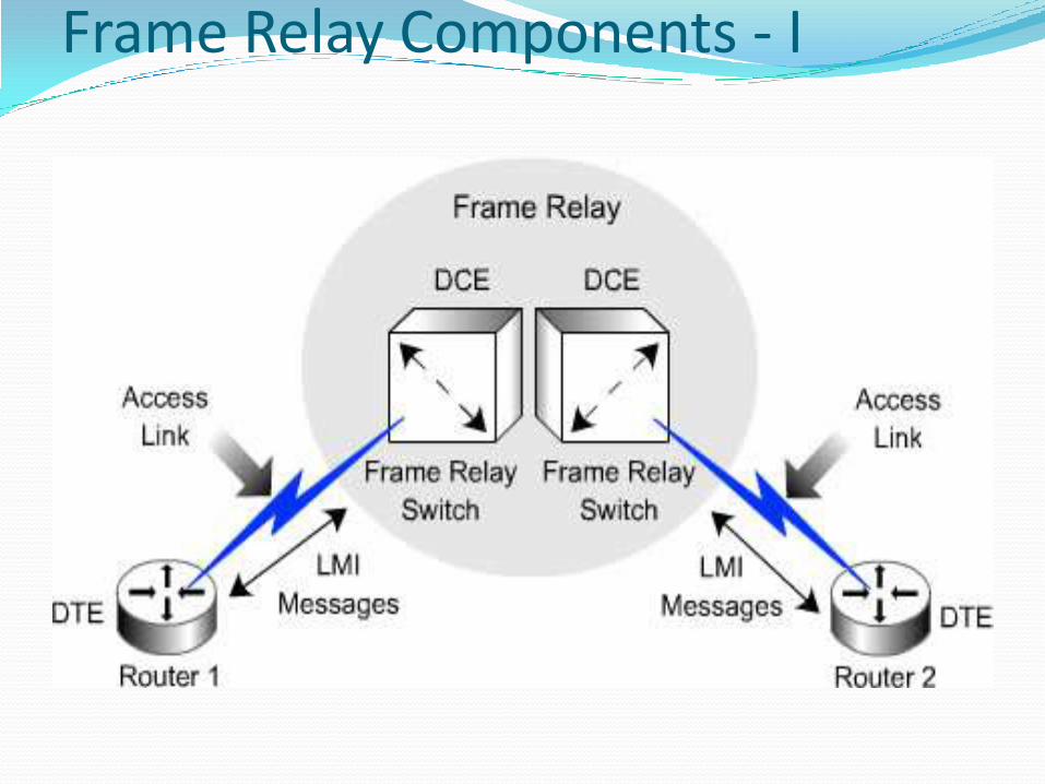
Frame Relay Components - I
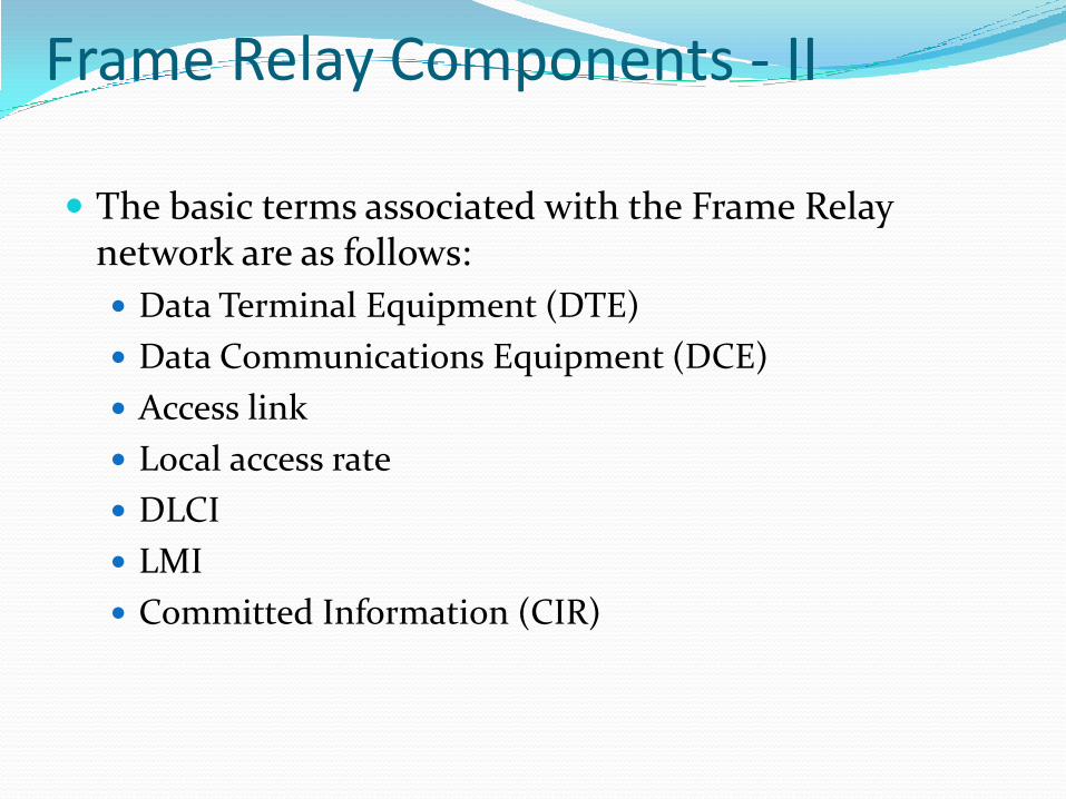
Frame Relay Components - II
The basic terms associated with the Frame Relay network are as follows:
Data Terminal Equipment (DTE)
Data Communications Equipment (DCE)
Access link
Local access rate
DLCI
LMI
Committed Information (CIR)
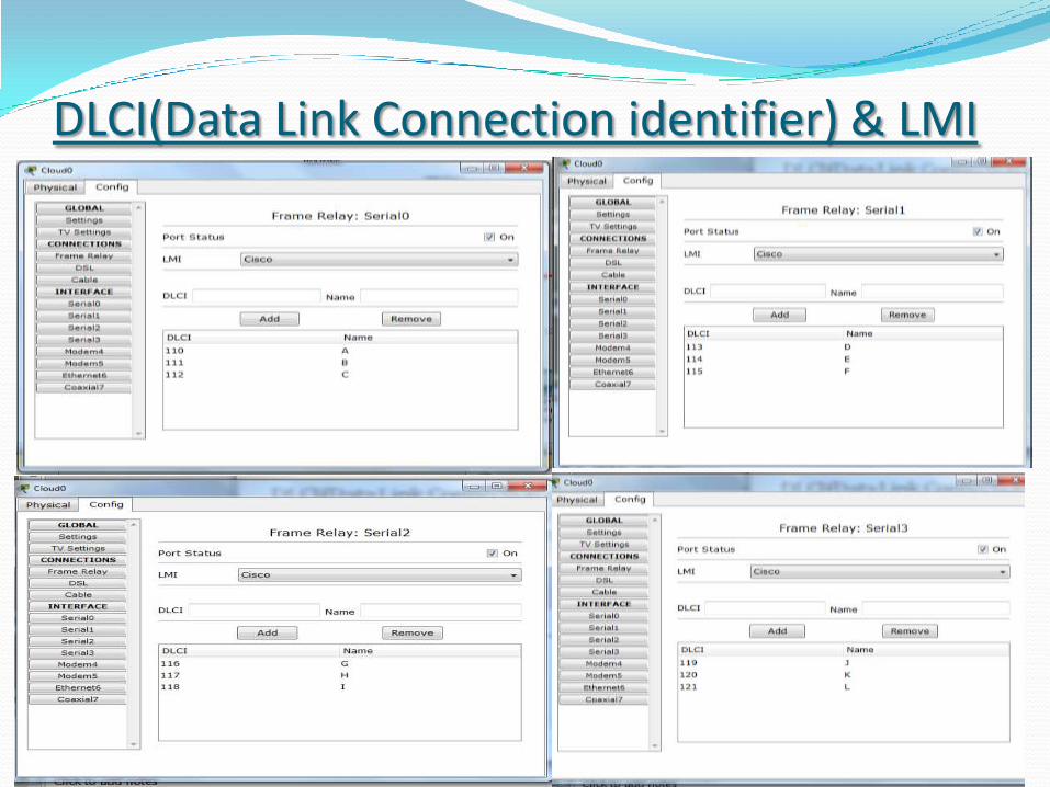
DLCI(Data Link Connection identifier) & LMI (local management interface)…
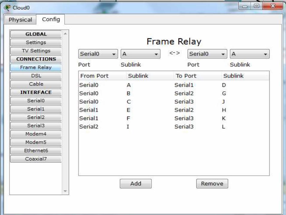

15
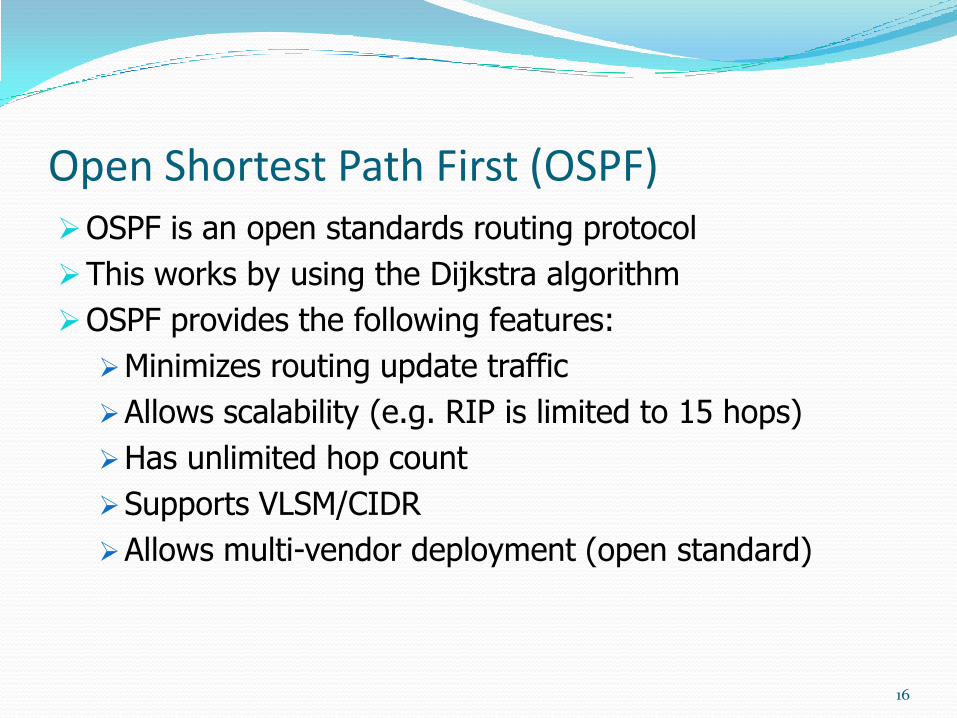
Open Shortest Path First (OSPF)OSPF is an open standards routing protocol
This works by using the Dijkstra algorithm
OSPF provides the following features:
Minimizes routing update traffic
Allows scalability (e.g. RIP is limited to 15 hops)
Has unlimited hop count
Supports VLSM/CIDR
Allows multi-vendor deployment (open standard)
16
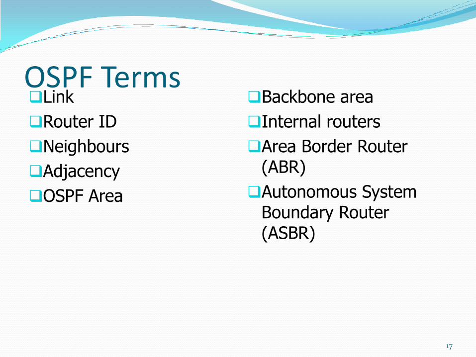
OSPF TermsLink
Router ID
Neighbours
Adjacency
OSPF Area
Backbone area
Internal routers
Area Border Router (ABR)
Autonomous System Boundary Router (ASBR)
17
LinkA network or router interface assigned to a given
network
Link (interface) will have "state" informationassociated with itStatus (up or down)
IP Address
Network type (e.g. Fast Ethernet)
Bandwidth
Addresses of other routers attached to this interface
18
OSPF Term: Link
19
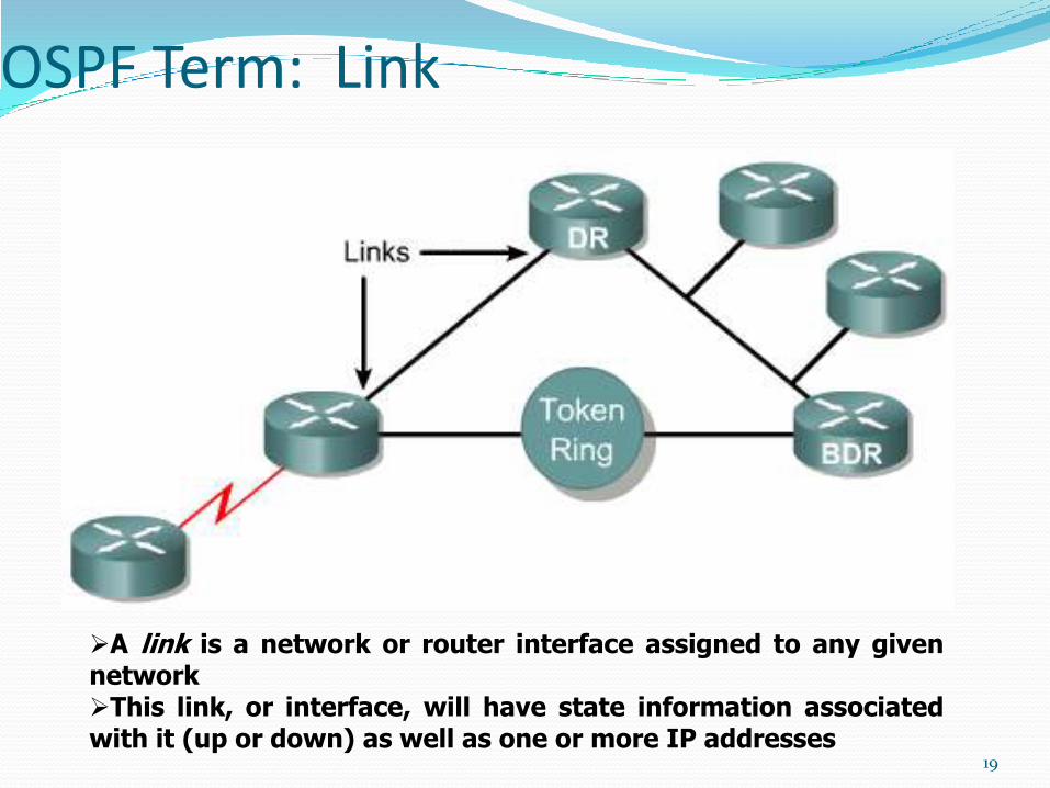
A link is a network or router interface assigned to any givennetworkThis link, or interface, will have state information associatedwith it (up or down) as well as one or more IP addresses
OSPF Term: Link State
20
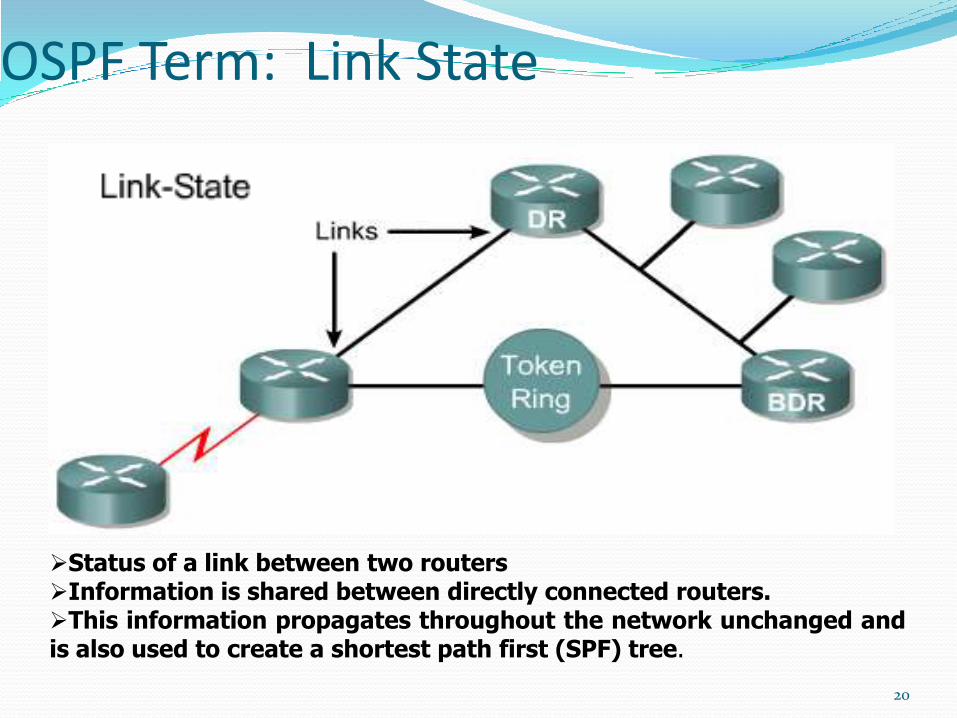
Status of a link between two routersInformation is shared between directly connected routers.This information propagates throughout the network unchanged andis also used to create a shortest path first (SPF) tree.
Router ID The Router ID (RID) is an IP address used to identify the router
Cisco chooses the Router ID by using the highest IP address of allconfigured loopback interfaces
If no loopback interfaces are configured with addresses, OSPF willchoose the highest IP address of all active physical interfaces.
You can manually assign the router ID.
The RID interface MUST always be up, therefore loopbacks arepreferred
21
NeighboursNeighbours are two or more routers that have an
interface on a common network
E.g. two routers connected on a serial link
E.g. several routers connected on a common Ethernetor Frame relay network
Communication takes place between / amongneighbours
neighbours form "adjacencies"
22
AdjacencyA relationship between two routers that permits the
direct exchange of route updates
Not all neighbours will form adjacencies
This is done for reasons of efficiency – more later
23
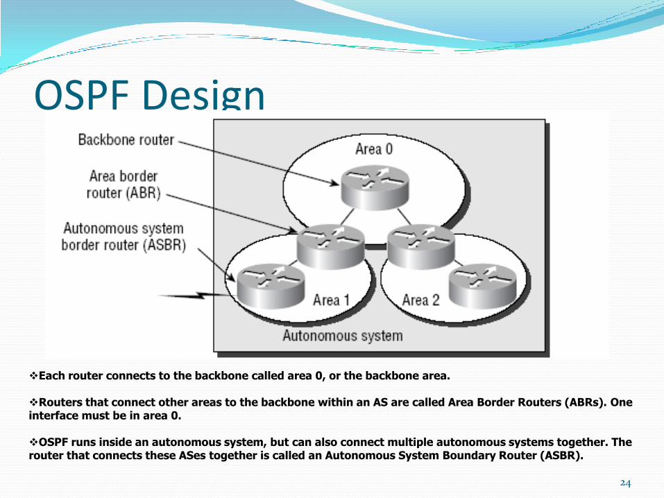
OSPF Design
24
Each router connects to the backbone called area 0, or the backbone area.
Routers that connect other areas to the backbone within an AS are called Area Border Routers (ABRs). One interface must be in area 0.
OSPF runs inside an autonomous system, but can also connect multiple autonomous systems together. The router that connects these ASes together is called an Autonomous System Boundary Router (ASBR).
25
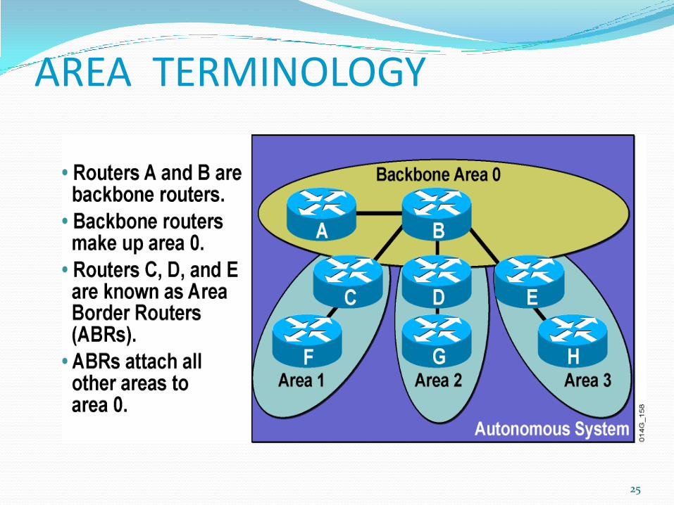
AREA TERMINOLOGY
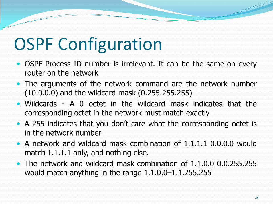
OSPF Configuration OSPF Process ID number is irrelevant. It can be the same on every
router on the network
The arguments of the network command are the network number(10.0.0.0) and the wildcard mask (0.255.255.255)
Wildcards - A 0 octet in the wildcard mask indicates that thecorresponding octet in the network must match exactly
A 255 indicates that you don’t care what the corresponding octet isin the network number
A network and wildcard mask combination of 1.1.1.1 0.0.0.0 wouldmatch 1.1.1.1 only, and nothing else.
The network and wildcard mask combination of 1.1.0.0 0.0.255.255would match anything in the range 1.1.0.0–1.1.255.255
26
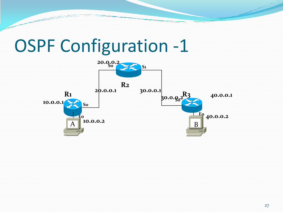
OSPF Configuration -1
27
R2
R1 R3
S0 S1
E0
S0
E0
S010.0.0.1
20.0.0.1
20.0.0.2
30.0.0.130.0.0.2 40.0.0.1
10.0.0.240.0.0.2
A B
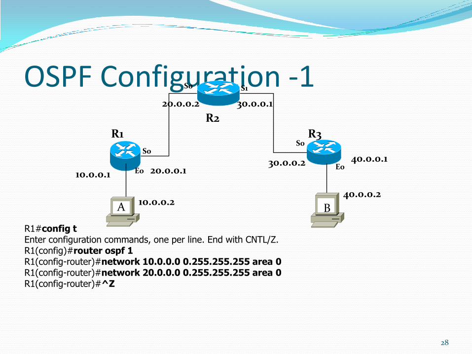
OSPF Configuration -1
28
R2
R1 R3
S0 S1
E0
S0
E0
S0
10.0.0.1 20.0.0.1
20.0.0.2 30.0.0.1
30.0.0.2 40.0.0.1
10.0.0.240.0.0.2
R1#config tEnter configuration commands, one per line. End with CNTL/Z.R1(config)#router ospf 1R1(config-router)#network 10.0.0.0 0.255.255.255 area 0R1(config-router)#network 20.0.0.0 0.255.255.255 area 0R1(config-router)#^Z
A B
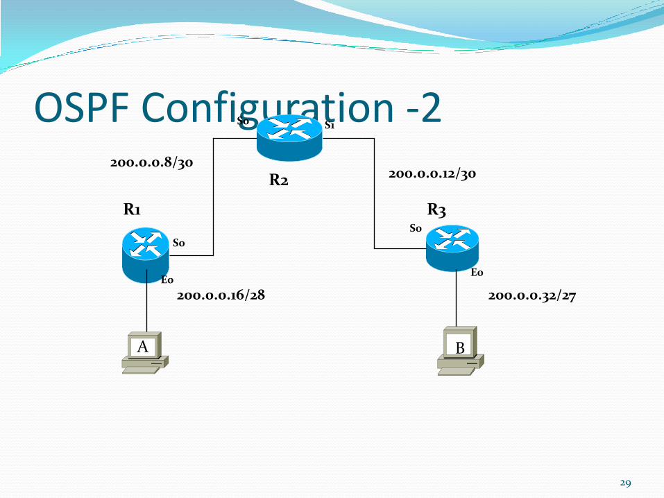
OSPF Configuration -2
29
R2
R1 R3
S0 S1
E0
S0
E0
S0
200.0.0.16/28
200.0.0.8/30200.0.0.12/30
200.0.0.32/27
A B
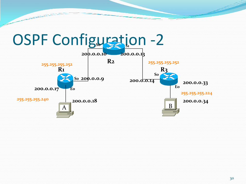
OSPF Configuration -2
30
R2
R1 R3
S0 S1
E0
S0
E0
S0
200.0.0.17
200.0.0.9
200.0.0.10 200.0.0.13
200.0.0.14 200.0.0.33
200.0.0.18 200.0.0.34255.255.255.240
255.255.255.252 255.255.255.252
255.255.255.224
A B
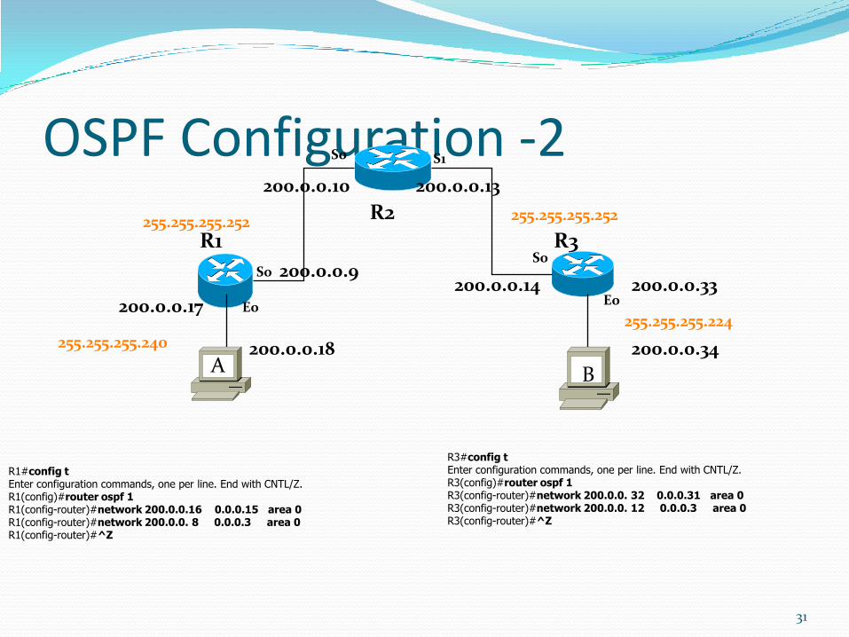
OSPF Configuration -2
31
R2
R1 R3
S0 S1
E0
S0
E0
S0
200.0.0.17
200.0.0.9
200.0.0.10 200.0.0.13
200.0.0.14 200.0.0.33
200.0.0.18 200.0.0.34255.255.255.240
255.255.255.252 255.255.255.252
255.255.255.224
R1#config tEnter configuration commands, one per line. End with CNTL/Z.R1(config)#router ospf 1R1(config-router)#network 200.0.0.16 0.0.0.15 area 0R1(config-router)#network 200.0.0. 8 0.0.0.3 area 0R1(config-router)#^Z
A B
R3#config tEnter configuration commands, one per line. End with CNTL/Z.R3(config)#router ospf 1R3(config-router)#network 200.0.0. 32 0.0.0.31 area 0R3(config-router)#network 200.0.0. 12 0.0.0.3 area 0R3(config-router)#^Z

10/22/2013 32