· pdf filemaguire shuttle granulators are protected by u.s. patent 6,405,949. ... negligence...
TRANSCRIPT

MAGUIRE PRODUCTS INC. Purging Recovery System
MAGUIRE® Purging Recovery System
INSTALLATION • OPERATION • MAINTENANCE
Copyright © Maguire Products, Inc. 2012

Maguire Products, Inc.
Edition: June 20, 2012 – PRS-20 2
Maguire Purging Recovery System

Maguire Products, Inc.
Edition: June 20, 2012 – PRS-20 3
Maguire Purging Recovery System
Maguire Purging Recovery System Copyright © 2012 Maguire Products Inc. The information contained within this manual including any translations thereof, is the property of Maguire Products Inc. and may not be reproduced, or transmitted in any form or by any means without the express written consent of Maguire Products Inc. To every person concerned with use and maintenance of the Maguire Purging Recovery System it is recommended to read thoroughly these operating instructions. Maguire Products Inc. accepts no responsibility or liability for damage or malfunction of the equipment arising from non-observance of these operating instructions. To avoid errors and to ensure trouble-free operation, it is essential that these operating instructions are read and understood by all personnel who are to use the equipment. Should you have problems or difficulties with the equipment, please contact Maguire Products Inc. or your local Maguire distributor. These operating instructions only apply to the equipment described within this manual. Manufacturer’s Contact Information Maguire Products Inc. 11 Crozerville Road Aston, PA. 19014 Phone: 610.459.4300 Fax: 610.459.2700 Website: http://www.maguire.com Email: [email protected]

Maguire Products, Inc.
Edition: June 20, 2012 – PRS-20 4
Maguire Purging Recovery System
Accuracy of this Manual
We make every effort to keep this manual as correct and current as possible. However, technology and product changes may occur more rapidly then the reprinting of this manual. Generally, modifications made to the Maguire Purging Recovery System design or to the operation of the software are may not reflected in the manual for several months. The date at the footer of this manual will indicate approximately how current this manual is. Likewise, your Maguire Purging Recovery System may have been produced at an earlier time and the information in this manual may not accurately describe your Maguire Purging Recovery System since this manual is written for the current line of Maguire Purging Recovery System in production (as of the date in the footer). We always reserve the right to make these changes without notice, and we do not guarantee the manual to be entirely accurate. If you question any information in this manual, or find errors, please let us know so that we may make the required corrections or provide you with accurate information. Additionally we will gladly provide you with an updated copy of any manuals you need at any time. We welcome comments and suggestions on ways we can improve this manual. For additional information, or to download the latest copy of this manual or any other Maguire manual, please visit our website or contact us directly. On the Web at: www.Maguire.com
Maguire Products Inc. Main Headquarters 11 Crozerville Road Aston, PA 19014 Tel: 610.459.4300 Fax: 610.459.2700 Email: [email protected]
Maguire Europe Tame Park Tamworth Staffordshire B775DY UK Tel: + 44 1827 265 850 Fax: + 44 1827 265 855 Email: [email protected]
Maguire Products Asia PTE LTD 45 Kallang Pudding Road #01-02 Alpha Building Singapore 349317 Tel: +65 6848 7117 Fax: +65 6744 3370 Email: [email protected]
Maguire Italy Via Zancanaro 40 35020 Vigorovea (PD) Tel: +39 049 970 54 29 Fax: +39 049 971 18 38 Email: [email protected]
Please e-mail comments and suggestions to: [email protected]

Maguire Products, Inc.
Edition: June 20, 2012 – PRS-20 5
Maguire Purging Recovery System
Table of Contents
PART 1 GETTING STARTED, READ THIS PAGE 7 1.1 5 Year Warranty and Disclaimers 8 1.2 SAFETY Warnings 9
1.3 Purging Recovery System Terminology 10 1.4 Concept and Principle of Operation 12
PART 2 INSTALLATION 13 2.1 Transport and Setup 13 2.2 Purging Recovery System Installation / Wiring 14 2.3 Final Checks Before Operation 16 PART 3 OPERATION 17
3.1 Standard Operation 17 3.2 Starting / Stopping the PRS-20 19
PART 4 MAINTENANCE AND SERVICE 20
4.1 General Maintenance 20 4.2 Preventative Maintenance Checklist 21 4.3 Installing New Shredder Rotor Knives 22 4.4 Adjustment of Lower Granulator Knife Gaps 24 4.5 Clearing a Jam 26 4.6 Drain and purge Air Filter / Regulator 27 4.7 Adjustments 27 4.8 Cleaning the PRS-20 28
PART 5 TROUBLESHOOTING 30 5.1 Troubleshooting - Symptoms/Cause 30
5.2 Clearing a Material Jam due to Plastic Melt 32 5.3 Cutting Chamber Hardware Diagram 34 5.4 PRS-20 Wiring Diagrams 36
PART 6 General Information 45
Our Design Philosophy 45 Warranty 46 Technical Support / Contact Information 47

Maguire Products, Inc.
Edition: June 20, 2012 – PRS-20 6
Maguire Purging Recovery System
Maguire Products, Inc.
Edition: June 20, 2012 – PRS-20 7
Maguire Purging Recovery System
1 - Getting Started – READ THIS PAGE PLEASE READ THIS PAGE
You don't have to read the entire manual.... BUT... PLEASE READ THE NEXT TEN PAGES. It will take about 10 minutes. THESE PAGES COVER:
Warranty and Disclaimers: What we Warranty and what we cannot promise.
SAFETY Warnings: Safety warnings.
INSTALLATION: Assembly and setup.
OPERATION: What buttons to push.
MAGUIRE Shuttle Granulators are protected by U.S. patent 6,405,949. Other U.S. and International patents are pending.
GETTING STARTED: PROCEED TO: WARRANTY AND DISCLAIMERS NEXT PAGE

Maguire Products, Inc.
Edition: June 20, 2012 – PRS-20 8
Maguire Purging Recovery System
1.1 - Warranty – Exclusive 5-Year
MAGUIRE PRODUCTS offers THE MOST COMPREHENSIVE WARRANTY in the plastics auxiliary equipment industry. We warrant each MAGUIRE PRS-20 manufactured by us to be free from defects in material and workmanship under normal use and service; excluding only those items listed below as 'excluded items'; our obligation under this warranty being limited to making good at our factory any PRS-20 which shall, within FIVE (5) YEARS after delivery to the original purchaser, be RETURNED intact to us, transportation charges PREPAID, and which our examination shall disclose to our satisfaction to have been thus defective; this warranty being expressly in lieu of all other warranties expressed or implied and of all other obligations or liabilities on our part, and MAGUIRE PRODUCTS neither assumes nor authorizes any other persons to assume for it any other liability in connection with the sale of its PRS-20. This warranty shall not apply to equipment repaired or altered outside MAGUIRE PRODUCTS INC. factory, unless such repair or alteration was, in our judgment, not responsible for the failure; nor which has been subject to misuse, negligence or accident, incorrect wiring by others, or installation or use not in accord with instructions furnished by Maguire Products, Inc. Our liability under this warranty will extend only to equipment that is returned to our factory in Aston, Pennsylvania, PREPAID. Please note that we always strive to satisfy our customers in whatever manner is deemed most expedient to overcome any problems they may have in connection with our equipment. Excluded Items: REPLACEMENT PARTS such as rotor knives, bed knives, belts, their associated hardware and removable screen ring or other "wear surfaces" etc. Disclaimers – Production of faulty product We will only be responsible to correct, repair, replace, or accept return for full refund, our equipment if it fails to perform as designed, or we have inadvertently misrepresented our equipment for your application. If for any reason this disclaimer is not acceptable, we will accept return of the equipment for full refund, including freight costs both ways.
GETTING STARTED: PROCEED TO: SAFETY WARNINGS NEXT PAGE

Maguire Products, Inc.
Edition: June 20, 2012 – PRS-20 9
Maguire Purging Recovery System
1.2 – SAFETY WARNINGS
SHARP EDGES: It is advisable to wear gloves and use a block of wood to move and "block" the rotor, or when attempting to remove partially ground product or service the PRS-20 blades. Knives Are Extremely Sharp!! Use extreme caution when placing your fingers or hands near the rotor knives.
DOOR SAFETY INTERLOCK: There are 4 safety interlocks switches on the front and rear doors as well as one safety interlock switch on the PRS-20’s containment chamber. If you open any of the doors or containment chamber, all operations will stop. After closing the doors, you will need to restart the PRS-20 properly. If Operation is abruptly stopped a possible material jam may occur. See Clearing a Jam for more information.
RISK OF SHOCK: Disconnect power supply before servicing the PRS-20. DO NOT OPEN electrical box without disconnecting power.
GETTING STARTED: PROCEED TO: INSTALLATION - NEXT PAGE

Maguire Products, Inc.
Edition: June 20, 2012 – PRS-20 10
Maguire Purging Recovery System
1.3 – Purging Recovery System Terminology Bed Guides White polypro strips running along the outside of the PRS-20’s
tables. These strips provide minimal clearance from the bottom of the containment chamber to the guide preventing material from leaking out during processing.
Bed Knife 2nd Stage Adjustable knife determining gap (clearance) to rotor
knife. All four edges of this knife are sharpened for maximum life. Blower Material movement system positioned below grinder Containment Chamber Hopper in which parts are placed & contained during processing Cylinders (1) pneumatic, (1) hydraulic that move containment chamber &
monitor pressure changes for protection against jamming Discharge Chute Chute which material drops into after being cut by R- Nine Follower Plate Polypropylene plate that lowers onto scrap parts being processed.
Keeps material close to shredder rotor for efficient processing Front of Machine Hinged doors in center. (drive motors are on back of machine) Granulator Machine designed to size reduce material to chips/granulate Grip Latches (1) located on each side on front of containment chamber keeping
cover securely closed. Home Position Containment chamber is stopped over upper table & in contact with
table limit stop Jack Screw Block White polypro blocks located on exterior lower right comers of
containment chamber. These blocks have a jam nut and a socket head set screw in them. When wheel assemblies are loosened, these blocks provide hopper clearance adjustment over bed guides.
Lifting Channels Two rectangular slot in front face of sound enclosure. These slots
allow forklift access so machine can be moved. Limit Switches Switches, which immediately terminate electrical current upon
activation. (Located on sound enclosure doors & containment chamber cover)
Lower Table Located to left of rotor when viewed from front of machine
Maguire Products, Inc.
Edition: June 20, 2012 – PRS-20 11
Maguire Purging Recovery System
Regulator Allows compressed air line to be connected. Regulates air pressure to pneumatic cylinders. (Do not adjust from factory setting of 90 psi without consulting Maguire Products
Reversing Circuit Monitors resistance encountered during containment chamber
travel. When resistance is met, unit reverses travel preventing overfeeding or jamming.
Lower Radial Granulator Performs 2nd stage of grinding (located under tables) Rotor Machined cutter with mounted knives Rotor Knife Fixed (non-adjustable) knife that is bolted to rotor Screen Ring Removable ring with drilled holes, which dictate particle size
(located in Lower Radial Granulator) Sensing Switch Switch mounted between hydraulic cylinder inlet/outlet. This switch
monitors hydraulic fluid movement. When no movement of fluid is detected for 2 seconds, (i.e. a "jam" condition) hopper will reverse direction.
Shredder Process where rotor performs 1st stage of grinding (located
between upper & lower tables) Shuttle Describes "Back & forth" movement of containment chamber Sound Enclosure Sound dampened panels mounted to machine minimizing DBA
level. Stripper Plate Machined plate mounted to lower bed with scalloped design.
Prevents long pieces of processed parts from making their way into transition discharge.
Timer Adds additional runtime after Shuttle Empty Alarm. Transition Discharge Removable chute that directs shredded material into Lower
Granulator. Upper Table Located to right of shredder rotor when viewed from front of
machine Wiper Blades Adjustable aluminum strips mounted to bottom of containment
chamber. Prevents material from escaping containment chamber & keeps upper & lower tables free of debris.

Maguire Products, Inc.
Edition: June 20, 2012 – PRS-20 12
Maguire Purging Recovery System
Purging Recovery System Concept The Maguire Purging Recovery System is a low cost alternative to conventional size-reduction of any large parts or purgings. This completely new type of plastics granulator automatically transforms large reject parts, purgings and other bulky or difficult-to-handle scrap into high-quality regrind but costs substantially less than conventional equipment. Until now, size-reducing large parts has meant buying a massive heavy-duty granulator, using a shredder in combination with a standard granulator, or cutting the parts with a saw before granulation. The PRS-20 is a two-stage system that in the first stage literally planes reject parts into small pieces. In this “planing” stage the scrap or reject part is automatically shuttled back and forth over a table surface that is split into two levels like a carpenter’s plane. Mounted in between the two levels is a staggered knife rotor that turns at 1750 rpm. This rotor reduces the scrap into small pieces and propels them into the hopper of a Radial Granulator. This Radial Granulator is positioned directly below the planer and performs the second stage by size reducing the pieces into highly uniform regrind meeting the particle size requirement of your operation. The final particle is then removed from the discharge chute by the Maguire Blower system & conveyed to a gaylord for storage. PRINCIPLES OF OPERATION
• The operator places the plastic part or bulk scrap into the containment chamber, or hopper, which is parked, at the home position at the upper level table. The containment chamber has two cylinders mounted to it. The first cylinder is pneumatic and solely provides the movement of the containment chamber. The second cylinder is hydraulic and has a switch mounted in-line, which monitors the movement of the fluid in the cylinder. If there is no movement of fluid, such as a jam condition, the switch senses this and reverses the hoppers direction of movement. The hydraulic cylinder also provides excellent shock absorbent qualities during the grinding process and containment chamber movement.
• Upon push-button activation by the operator, the follower plate releases and applies gentle
pressure on the parts) being ground. The containment chamber shuttles on wheels toward the lower level table.
• The scrap then passes over the rotor, which is turning in the same direction as the Shuttle's
movement.
• When the containment chamber reaches the farthest end of the lower table it is restricted from moving any further. The hydraulic sensor detects no movement in fluid and reverses the containment chambers direction. The part is now being fed into the rotor knives, which are turning into the part.
• Small pieces produced by the rotor knife are propelled downward into the hopper of the Radial
Granulator for final size reduction.
• The fine particles are removed from the Radial Granulator discharge chute by the blower. The particle is conveyed through 3 inch tube into a gaylord container.
• This shuttling process continues until the Hopper Empty Alarm or the operator manually stops
the machine for reloading.
Maguire Products, Inc.
Edition: June 20, 2012 – PRS-20 13
Maguire Purging Recovery System
2 - Installation 2.1 – Transport, Setup
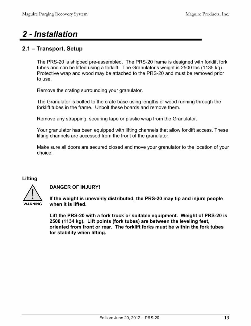
The PRS-20 is shipped pre-assembled. The PRS-20 frame is designed with forklift fork tubes and can be lifted using a forklift. The Granulator’s weight is 2500 lbs (1135 kg). Protective wrap and wood may be attached to the PRS-20 and must be removed prior to use. Remove the crating surrounding your granulator. The Granulator is bolted to the crate base using lengths of wood running through the forklift tubes in the frame. Unbolt these boards and remove them. Remove any strapping, securing tape or plastic wrap from the Granulator. Your granulator has been equipped with lifting channels that allow forklift access. These lifting channels are accessed from the front of the granulator. Make sure all doors are secured closed and move your granulator to the location of your choice.
Lifting
DANGER OF INJURY! If the weight is unevenly distributed, the PRS-20 may tip and injure people when it is lifted. Lift the PRS-20 with a fork truck or suitable equipment. Weight of PRS-20 is 2500 (1134 kg). Lift points (fork tubes) are between the leveling feet, oriented from front or rear. The forklift forks must be within the fork tubes for stability when lifting.

Maguire Products, Inc.
Edition: June 20, 2012 – PRS-20 14
Maguire Purging Recovery System
2.2 – PRS-20 Installation Electrical Connection
RISK OF INJURY! Only qualified technicians should make electrical connections. Connect Motor Power to PRS-20 After initial setup of the Granulator, the power cable must be connected. The electrical cable is located on the left side of the Granulator and supplies the power. Within the cable are four wires. These wires are black, brown, blue and fourth wire is a green/yellow wire is the ground wire. WIRING YOUR GRANULATOR AND ASSURING PROPER ROTATION The following procedure will guide you in supplying power to your granulator. Your granulators requires a 20amp Breaker & is wired for 60 cycle / 3 phase.
1. Select The Proper Male Cord Cap To Match Your Electrical Supply.
2. Remove Approx. Four Inches Of Rubber Coating On Cord To Expose Coated Wires.
3. Remove Approx. Y2 Inch Of Plastic Coating From Each Of The Four Leads.
4. Attach your Male Cord Cap as required by local code.
5. Plug Granulator Into Power Supply.
6. Turn the granulator power disconnect to the "ON" position.
Press The Start Button for the Blower, the grinder & 3rd sequence "Shuttle Rotor".

Maguire Products, Inc.
Edition: June 20, 2012 – PRS-20 15
Maguire Purging Recovery System
Check The Motors For Proper Rotation
Important: The blower, shredder & second stage motors all use 3-phase. Therefore, it is only necessary to assure that one motor is turning in the correct direction. From the front of the granulator, the shredder rotor should be turning in a "counterclockwise" direction.
If The Motor Is Not Turning In The Correct Direction: 1. Turn Off The Grinder and follow proper lockout/tagout procedures.
2. Remove power cable from the power source. 3. DO NOT REMOVE THE GREEN GROUND WIRE. 4. Swap Any Two (2) Of The Other Three (3) Wires In The Lord Cap And Secure. 5. Reassemble Cord, Connect To Power Supply & Recheck For Proper Rotation. If Proper Rotation Is Observe: Supply the granulator with compressed air & assure regulator is set at 90 psi.
Follow this procedure if the PRS-20 has been serviced or it is necessary to check the rotation of all 3 motors individually:
Blower Motor: The blower motor is located within the front door below the bed rails. Remove the black convey line. Observe the rotation during operation. It should rotate in a counter-clockwise direction.
DO NOT reach into the blower!
Grinder Motor: The grinder motor is located in the back of the PRS-20 below the bed rails. Observe the rotation during operation. It should rotate in a counter-clockwise direction.
Shredder Motor: From the front of the granulator, the shredder rotor
should be turning in a "counterclockwise" direction.
If any ONE of the three motors are not turning in The Correct Direction (counter-clockwise), then follow these steps: 1. Turn Off The Grinder, follow proper lockout/tagout procedures. 2. Remove power cable from the power source. 3. Open the Electrical cabinet and locate the motor starter
contactors / overload relays. See labeled photo at right. 4. Located the specific relay that needs to be corrected. 5. Swap any two (2) of the other three (3) wires and secure. Connect To Power Supply & Recheck For Proper Counter-clockwise Rotation.
Maguire Products, Inc.
Edition: June 20, 2012 – PRS-20 16
Maguire Purging Recovery System
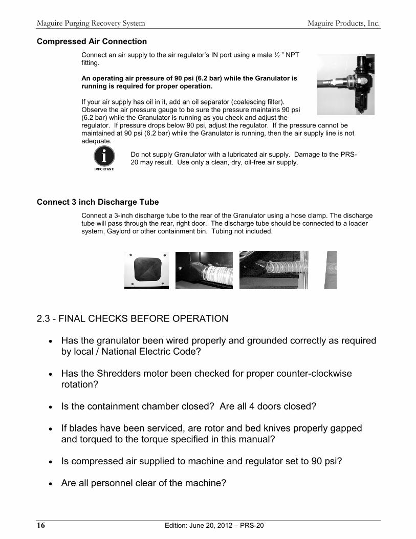
Compressed Air Connection Connect an air supply to the air regulator’s IN port using a male ½ ” NPT
fitting. An operating air pressure of 90 psi (6.2 bar) while the Granulator is running is required for proper operation. If your air supply has oil in it, add an oil separator (coalescing filter). Observe the air pressure gauge to be sure the pressure maintains 90 psi (6.2 bar) while the Granulator is running as you check and adjust the regulator. If pressure drops below 90 psi, adjust the regulator. If the pressure cannot be maintained at 90 psi (6.2 bar) while the Granulator is running, then the air supply line is not adequate.
Do not supply Granulator with a lubricated air supply. Damage to the PRS-20 may result. Use only a clean, dry, oil-free air supply.
Connect 3 inch Discharge Tube Connect a 3-inch discharge tube to the rear of the Granulator using a hose clamp. The discharge
tube will pass through the rear, right door. The discharge tube should be connected to a loader system, Gaylord or other containment bin. Tubing not included.
2.3 - FINAL CHECKS BEFORE OPERATION
• Has the granulator been wired properly and grounded correctly as required by local / National Electric Code?
• Has the Shredders motor been checked for proper counter-clockwise
rotation?
• Is the containment chamber closed? Are all 4 doors closed?
• If blades have been serviced, are rotor and bed knives properly gapped and torqued to the torque specified in this manual?
• Is compressed air supplied to machine and regulator set to 90 psi?
• Are all personnel clear of the machine?

Maguire Products, Inc.
Edition: June 20, 2012 – PRS-20 17
Maguire Purging Recovery System
3 - Operation 3.1 - Standard Operation CONTROLS & ADJUSTMENTS Start/Stop Controls Overview
Regulator Provides connection of compressed air. (Adjustment of pressure
should not be made without consultation of Maguire Products personnel)
Emergency Stop Emergency Stop Button (located on front of control
box) Press button "fully" inward to stop all electrical current to the motors. The button will stay depressed. Rotate button ¼ turn clockwise to release button.
Disconnect Main Disconnect For Lockout/Tagout (located on side of control
box) Blower Material Movement System. Evacuates Material From Discharge
Chute Grinder Controls 2nd Stage Lower Radial Granulator (located under tables) Shredder Controls 1st Stage Shredder Rotor (located between split tables) Shuttle Controls Back & Forth "Shuttling" Of Containment Chamber
(hopper) Timer Adds additional runtime after Shuttle Empty Alarm
(minutes)
Maguire Products, Inc.
Edition: June 20, 2012 – PRS-20 18
Maguire Purging Recovery System
Adjustments
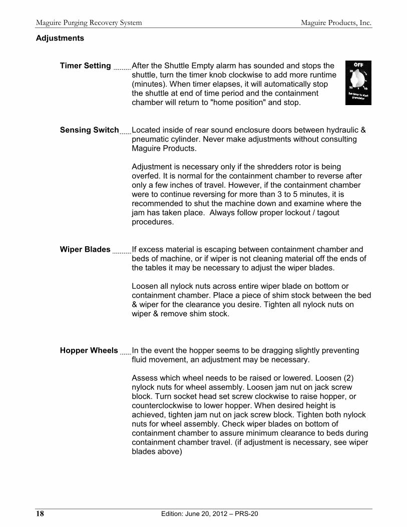
Timer Setting After the Shuttle Empty alarm has sounded and stops the shuttle, turn the timer knob clockwise to add more runtime (minutes). When timer elapses, it will automatically stop the shuttle at end of time period and the containment chamber will return to "home position" and stop.
Sensing Switch Located inside of rear sound enclosure doors between hydraulic &
pneumatic cylinder. Never make adjustments without consulting Maguire Products.
Adjustment is necessary only if the shredders rotor is being overfed. It is normal for the containment chamber to reverse after only a few inches of travel. However, if the containment chamber were to continue reversing for more than 3 to 5 minutes, it is recommended to shut the machine down and examine where the jam has taken place. Always follow proper lockout / tagout procedures.
Wiper Blades If excess material is escaping between containment chamber and
beds of machine, or if wiper is not cleaning material off the ends of the tables it may be necessary to adjust the wiper blades.
Loosen all nylock nuts across entire wiper blade on bottom or containment chamber. Place a piece of shim stock between the bed & wiper for the clearance you desire. Tighten all nylock nuts on wiper & remove shim stock.
Hopper Wheels In the event the hopper seems to be dragging slightly preventing
fluid movement, an adjustment may be necessary.
Assess which wheel needs to be raised or lowered. Loosen (2) nylock nuts for wheel assembly. Loosen jam nut on jack screw block. Turn socket head set screw clockwise to raise hopper, or counterclockwise to lower hopper. When desired height is achieved, tighten jam nut on jack screw block. Tighten both nylock nuts for wheel assembly. Check wiper blades on bottom of containment chamber to assure minimum clearance to beds during containment chamber travel. (if adjustment is necessary, see wiper blades above)
Maguire Products, Inc.
Edition: June 20, 2012 – PRS-20 19
Maguire Purging Recovery System
3.2 - Starting / Stopping the PRS-20 Starting Your PRS-20
1. Assure Compressed Air Is Supplied To Regulator.
2. Open the Access Door On The Front of the machine. Rotate handle ¼ turn to open door.
3. Open the Containment Chamber cover. Unlatch the (2) rubber grip latches.
4. Load your parts into the Containment Chamber.
5. Close the Containment Chamber cover. Secure both rubber grip latches.
6. Close Access Door On The Front of Machine & Secure Door Fasteners.
7. Turn Electrical Disconnect to "ON' position.
8. Press Blower "START" button.
9. Press Grinder "START" button.
10. Press Shredder "START" button.
11. Press Shuttle "START" button.
Stopping Your PRS-20
IMPORTANT: Manual stop the PRS-20 should use this procedure:
1. Turn Timer dial "counterclockwise" to zero if not already at zero.
2. Press Shuttle “STOP” button.
3. Wait 30 seconds for the Shuttle to return and stop.
4. Press Shredder "STOP" button (this will stop rotor from producing material chips &
feeding them into the Radial Granulator positioned below)
5. Wait 60 seconds to allow Radial Granulator to process material chips.
6. Press Grinder "STOP" button
7. Wait 30 seconds to allow Blower to fully evacuate discharge chute
8. Press Blower "STOP" button
9. Turn Disconnect to "OFF position & follow proper LOCKOUT / TAGOUT procedure
Maguire Products, Inc.
Edition: June 20, 2012 – PRS-20 20
Maguire Purging Recovery System
4 – Maintenance and Service 4.1 – General Maintenance SHREDDER DRIVE BELTS: 2 belts drive the shredders rotor. These belts should be checked for proper tensioning at least once per week or every 40 hours of runtime. SHREDDER ROTOR BEARINGS: There are two Shredder Rotor Bearings, 1 inside front door of sound enclosure, 1 is inside rear door of sound enclosure. These bearings should be checked weekly to determine scheduled maintenance period. Lubrication should be NLGI Grade 2 INSTALLING NEW ROTOR & BED KNIVES: When installing new knives, it is advisable that you purchase new bolts and washers from Maguire Products Inc. and install them all in new condition at that time. KNIFE GAPPING AND WEAR: The gapping between the rotor knives and the bed knives should be checked prior to initial startup and routinely as governed by your application. Knives should be gapped when there is a significant drop in production rates or an unacceptable increase in heat generation or fines. ROTOR KNIFE AND BED KNIFE HARDWARE: The Lower Radial Granulator rotor and bed knife bolts are a standard 1960 series socket head cap screws. The Shuttles rotor knife bolts are Grade 8 hex head bolts. Due to the constant torqueing and stretching of the bolts threads, it is recommended each rotor knife bolt, bed knife bolt and heat treated washer be replaced with each knife change. ROTOR KNIFE AND BED KNIFE RECOMMENDED TORQUE SETTINGS: It is recommended that the rotor knives and bed knives be properly torqued with the following settings at each knife change and be checked periodically between knife changes.
Shuttle Rotor Knives Torque Setting: 102 ft. lbs SCREEN RING CONDITION: Inspect the screen ring during each clean out for wear, cracks and elongation of the holes. REPLACEMENT OF ASSOCIATED HARDWARE: Substitution of improper hardware could lead to void of warranty, premature failure, equipment damage, and serious injury to personnel.

Maguire Products, Inc.
Edition: June 20, 2012 – PRS-20 21
Maguire Purging Recovery System
4.2 – Preventative Maintenance Checklist After Each Batch:
• Remove any loose material sitting on the planing table. (Use Shop Vac or Whiskbroom / dust pan to clean).
• Make sure the granulate receptacle is not full and has enough space to accept the volume of the next batch.
Daily:
• Check the Air Pressure Regulator setting, should be 90psi. • Check the 3-inch Discharge Hose between grinder and blower for wear or
holes. Make sure it is clear. Weekly:
• Check the alignment cables on the Hopper Lid for slight even tension. • Check the Rotor bearing mounting bolts (8) for tightness. • Inspect the Hopper hydraulic system for leaks. • Remove the Belt Cover (back of machine) and inspect the Belts for
tightness and wear. Monthly:
• Inspect the Rotor Blades for dull cutting edges, replace for best cutting efficiency.
• Inspect the R-9 Blades for dull cutting edges, replace for best cutting efficiency.
• Inspect R-9 screen ring for wear and replace as necessary. • Check the Hopper bolts for tightness. • Set R-9 knife gap to 5 – 7 thousandths” • Inspect shuttle box end plate wiper blades. Blades should be centered with
20 thousandths clearance between wiper blade and table. Yearly:
• The Rotor bearings have a grease fitting. Should greasing be need use LPS Thermaplex Hi Load bearing grease or equal. (Graingers part no. 4UJ40)
• Check the Hopper Lid rubber latches for wear. • Check (4) safety door interlocks to confirm proper function.

Maguire Products, Inc.
Edition: June 20, 2012 – PRS-20 22
Maguire Purging Recovery System
4.3 – Installing New Shredder Rotor Knives Required Tools: Torque Wrench capable of 102 ft. lbs.
THIS PROCEDURE IS DONE FROM THE UNDER SIDE OF THE MACHINE. NEVER GET INSIDE CONTAINMENT CHAMBER!
It is advisable to wear gloves and use a block of wood to move and "block" the rotor, or when attempting to remove partially ground product. Knives Are Extremely Sharp!! Use extreme caution when placing your fingers or hands near the rotor knives.
The following procedure will guide you in safely changing your shredder rotor knives. Follow proper shutdown procedure as described in Starting / Stopping the PRS-20 on page 19.
1. Open the Access Door On The End of the machine. Rotate fastener ½ turn counterclockwise to open door.
2. Open the Containment Chamber cover.
Unlatch the rubber grip handle. Slowly turn safety knob counterclockwise until it is fully unthreaded.
3. Remove All Residual Product from the Containment Chamber.
4. Open the Front Access Door.
Rotate fastener ½ turn counterclockwise to open door.
5. Remove the Transition Discharge. Lift latch on right side of guides and swing 1/4" thick stop 90 degrees outward so discharge can be removed While supporting the transition discharge, gently slide the chute outward until it is removed from the machine.
6. Wedge A Piece Of Wood Between The Tip Of A Rotor Knife & The Upper Bed To
Prevent Rotor From Moving.
7. Loosen (2) Hex Head Bolts on knife.
8. Remove Old Knife
9. Place New Knife in rotor firmly seating back of knife against heel/knife seat of rotor.

Maguire Products, Inc.
Edition: June 20, 2012 – PRS-20 23
Maguire Purging Recovery System
10. Tighten (2) Hex Head Bolts On Rotor Knife
11. Very Important! Torque Bolts To 102 ft. Ibs with torque wrench.
12. Remove block of wood and repeat Steps 1- 6 for remaining knives.
13. Reinstall the Transition Discharge. Slide the transition discharge in towards the back of the granulator cabinet until it stops. Swing discharge arm stop against chute. Hold pressure against arm stop and press latch downward to lock arm in place.
· 14. Close the Containment Chamber cover and secure both rubber grip latches.
15. Close & Secure Access Door On The Front & Back Of The Machine.
16. Restore the Electrical Power Source.
17. Restart your Granulator. See Starting / Stopping the PRS-20 on page 19.
Maguire Products, Inc.
Edition: June 20, 2012 – PRS-20 24
Maguire Purging Recovery System
4.4 – Adjustment of Lower Granulator Knife Gaps We recommend that knife gapping be checked at least once per week. This period of time may vary depending upon the type of material you are granulating and the frequency of use. Any increase in dusting or fines that is experienced on or within the granulator is a sign that your knives are dull or their gap is excessive. However, some materials are inherent to dusting. We do not recommend setting the gap between your rotor knives and bed knives at less than .004 inch.
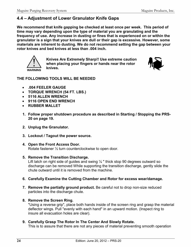
Knives Are Extremely Sharp!! Use extreme caution when placing your fingers or hands near the rotor knives.
THE FOLLOWING TOOLS WILL BE NEEDED
• .004 FEELER GAUGE • TORQUE WRENCH (54 FT. LBS.) • 5116 ALLEN WRENCH • 9116 OPEN END WRENCH • RUBBER MALLET
1. Follow proper shutdown procedure as described in Starting / Stopping the PRS-
20 on page 19.
2. Unplug the Granulator.
3. Lockout / Tagout the power source.
4. Open the Front Access Door. Rotate fastener ½ turn counterclockwise to open door.
5. Remove the Transition Discharge. Lift latch on right side of guides and swing ¼ " thick stop 90 degrees outward so discharge can be removed While supporting the transition discharge, gently slide the chute outward until it is removed from the machine.
6. Carefully Examine the Cutting Chamber and Rotor for excess wear/damage.
7. Remove the partially ground product. Be careful not to drop non-size reduced particles into the discharge chute.
8. Remove the Screen Ring. "Using a reverse grip", place both hands inside of the screen ring and grasp the material deflector wings. Pull "evenly with each hand" in an upward motion. (Inspect ring to insure all evacuation holes are clear).
9. Carefully Grasp The Rotor In The Center And Slowly Rotate. This is to assure that there are not any pieces of material preventing smooth operation
Maguire Products, Inc.
Edition: June 20, 2012 – PRS-20 25
Maguire Purging Recovery System
or that will prevent screen ring from being properly installed
There is an adjusting screw for each of the three (3) bed knives.
10. Slightly Loosen the Socket Head Cap Screw that holds the bed knife down
11. Loosen the Jam Nut on the bed knife adjusting screw.
12. Using the Bed Knife Adjusting Bolts And Your Feeler Gauge, Slowly turn bed
knife adjusting bolt clockwise to reduce knife gap to desired clearance. In the event that the bed knife gap is now "too tight", back off the bed knife adjusting screw and gently tap the bed knife (using a rubber mallet) away from the rotor knife, then repeat Step #3 above until desired gap is achieved. Check this gap to both rotor knives in case one is more worn than the other.
13. Tighten the Socket Head Cap Screw that anchors the bed knife downward to a required torque setting of 54 ft. lbs
14. Assure that the Bed Knife Adjusting Bolt is in contact with the bed knife.
15. Tighten the Jam Nut while holding the adjusting screw "still".
16. Re-Check your Knife Gap to assure that the clearance has not changed Repeat Steps 10 through 16 For the Remaining bed knives. Reassemble Components As Follows:
1. Carefully Align and reinsert the Screen Ring utilizing the same reverse grip.
2. Assure that Discharge Chute is clear of all residual material.
3. Reinstall the Transition Discharge.
4. Slide the transition discharge in towards the back of the granulator cabinet until it stops. Swing discharge arm stop against chute. Hold pressure against arm stop and press latch downward to lock arm in place.
5. Close & Secure the Sound Enclosure Doors.
6. Restore the Electrical Power Source & Compressed Air.
7. Plug in the Granulator.
8. Restart your Granulator. See Starting / Stopping the PRS-20 on page 19.

Maguire Products, Inc.
Edition: June 20, 2012 – PRS-20 26
Maguire Purging Recovery System
4.5 – Clearing a Jam The following procedure will guide you in safely clearing a jam that has caused your granulator to stop.
It is advisable to wear gloves and use a block of wood to move and "block" the rotor, or when attempting to remove partially ground product. Knives Are Extremely Sharp!! Use extreme caution when placing your fingers or hands near the rotor knives.
Always work from the top of the machine down. Do not thoroughly clean out the Lower Radial Granulator before the shredder rotor. Because when you clean out the shredder rotor, some material will fall down into the Lower Radial Granulator preventing it from restarting.
1. Unplug the Granulator
2. Lockout / Tagout the granulator & the power source.
3. Open the Access Door On The Front of the machine. Rotate fasteners ½ turn to open door.
4. Open the Containment Chamber cover.
Unlatch the 2 rubber grip latches.
5. Remove All Residual Product from the Containment Chamber.
6. Carefully Examine the Containment Chamber and Rotor to determine where the jam has taken place.
7. Using a block of wood against rotor knife tip, turn rotor until it moves freely. Be extremely careful when removing product from around rotor. After rotor is turning freely, Close the Containment Chamber cover and secure the 2 rubber grip latches.
8. Remove the Transition Discharge. Lift latch on right side of guides and swing 1/4" thick stop 90 degrees outward so discharge can be removed While supporting the transition discharge, gently slide the chute outward until it is removed from the machine.
9. Carefully Examine the Cutting Chamber and Rotor to determine where the jam has taken place.
10. Remove The Partially Ground Product. Be careful not to drop particles into the Radial Granulator discharge chute
11. Remove the Screen Ring "Using a reverse grip ", place both hands inside of the screen ring and grasp the material deflector wings. Pull "evenly with each hand" in an upward motion. (Inspect ring

Maguire Products, Inc.
Edition: June 20, 2012 – PRS-20 27
Maguire Purging Recovery System
to insure all evacuation holes are clear)
12. Carefully Grasp The Rotor In The Center And Slowly Rotate This is to assure that there are not any pieces of material preventing smooth operation or that will prevent screen ring from being properly installed Carefully Align and reinsert the Screen Ring utilizing the same reverse grip.
13. Reinstall the Transition Discharge Slide the transition discharge in towards the back of the granulator cabinet until it stops. Swing discharge arm stop against chute. Hold pressure against arm stop and press latch downward to lock arm in place.
14. Release the 2 Discharge Chute latches on each side of chute & remove
15. Clean Out Chute area of all residual material.
16. Close & Secure the Front Access Door On The Sound Enclosure.
17. Fully Depress Reset Buttons for grinder & shredder thermal overload in control box.
18. Restore the Electrical Power Source.
19. Plug in the Granulator.
20. Restart your Granulator. See Starting / Stopping the PRS-20 on page 19. 4.6 – Drain and purge Air Filter / Regulator
The purpose of the air filter is to remove moisture and contaminants from the air supply and protect the air components of the Granulator. The air filter must be periodically purged of moisture.
Do not supply the Granulator with a lubricated air supply. Damage may result. Use only a clean, dry, oil-free air supply.
4.7 – Adjustments
Air Pressure
We recommend a pressure setting of 90 PSI while the Granulator is running. The gauge should continue to read this setting even when the vacuum unit is on. If it does not maintain pressure your supply line is not sized properly.
Do not supply the Granulator with a lubricated air supply. Damage may result. Use only a clean, dry, oil-free air supply.
Maguire Products, Inc.
Edition: June 20, 2012 – PRS-20 28
Maguire Purging Recovery System
4.8 – Cleaning the Granulator Follow "Stopping the Granulator" in Starting / Stopping the PRS-20 19 prior To Shutdown The following procedure will guide you in safely cleaning your granulator. A Thorough Cleanout Cannot Be Performed Without Using An Air Blow Gun
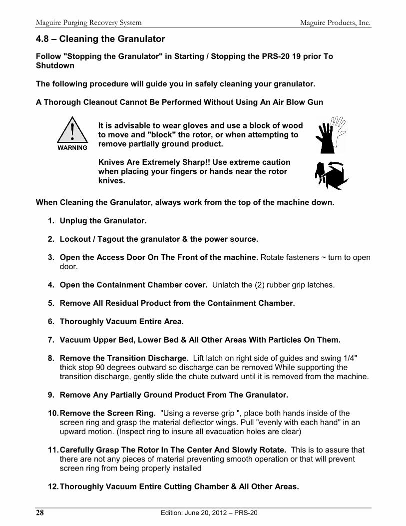
It is advisable to wear gloves and use a block of wood to move and "block" the rotor, or when attempting to remove partially ground product. Knives Are Extremely Sharp!! Use extreme caution when placing your fingers or hands near the rotor knives.
When Cleaning the Granulator, always work from the top of the machine down.
1. Unplug the Granulator.
2. Lockout / Tagout the granulator & the power source.
3. Open the Access Door On The Front of the machine. Rotate fasteners ~ turn to open door.
4. Open the Containment Chamber cover. Unlatch the (2) rubber grip latches.
5. Remove All Residual Product from the Containment Chamber.
6. Thoroughly Vacuum Entire Area.
7. Vacuum Upper Bed, Lower Bed & All Other Areas With Particles On Them.
8. Remove the Transition Discharge. Lift latch on right side of guides and swing 1/4" thick stop 90 degrees outward so discharge can be removed While supporting the transition discharge, gently slide the chute outward until it is removed from the machine.
9. Remove Any Partially Ground Product From The Granulator.
10. Remove the Screen Ring. "Using a reverse grip ", place both hands inside of the screen ring and grasp the material deflector wings. Pull "evenly with each hand" in an upward motion. (Inspect ring to insure all evacuation holes are clear)
11. Carefully Grasp The Rotor In The Center And Slowly Rotate. This is to assure that there are not any pieces of material preventing smooth operation or that will prevent screen ring from being properly installed
12. Thoroughly Vacuum Entire Cutting Chamber & All Other Areas.

Maguire Products, Inc.
Edition: June 20, 2012 – PRS-20 29
Maguire Purging Recovery System
13. Release the 2 Discharge Chute latches on each side of chute & remove.
14. Vacuum the Transition Discharge.
15. Vacuum Chute area.
16. Using Air Blow Gun Thoroughly Blow Off All Areas / Components, working from the top of the machine downward to the floor.
17. Reinstall Screen Ring (using same reverse grip)
18. Reinstall the Transition Discharge. Slide the transition discharge in towards the back of the granulator cabinet until it stops. Swing discharge arm stop against chute. Hold pressure against arm stop and press latch downward to lock arm in place.
19. Reinstall Discharge Chute & Secure Both Latches.
20. Close the Containment Chamber Cover and secure both grip latches.
21. Close Access Door On The Front Of Machine & Secure Knobs.
22. Restore the Electrical Power Source.
23. Plug in the Granulator.
24. Restart your Granulator. See Starting / Stopping the PRS-20 on page 19.
Maguire Products, Inc.
Edition: June 20, 2012 – PRS-20 30
Maguire Purging Recovery System
5 – Troubleshooting OVERVIEW This section is intended to serve as a guide in checking on possible
problems that may occur with the operation of your granulator. SAFETY The most important ingredient in any business or industry is a constant
adherence to sound safety practices. The best way to assure safety in any activity that involves troubleshooting or repairing the granulator is to retain complete control of the machine. The most effective way to accomplish this on a consistent basis is to: TURN OFF THE POWER LOCK OUT THE POWER SOURCE TAG THE MACHINE - "DO NOT OPERATE"
DIAGNOSIS OF THE PROBLEM When you are correcting what may appear to be a malfunction, it is recommended that you check your facilities associated circuitry, and assemblies to ensure that there are no other defective devices. If the root cause of the problem appears to be related to the granulator, it is imperative that you contact Maguire Products, U.S.G. Division before disassembling any components. TROUBLESHOOTING GUIDE Troubleshooting techniques are listed in the following pages. But regardless of the problem that presents itself, remember to approach all situations in a guarded, safe manner with full awareness of those working in the area.
5.1 – Troubleshooting - Symptoms/Cause
1. Motor Fails To Start • Safety Interlocks are not satisfied or inoperative (i.e. door is not closed
completely). • Starter overload is "tripped-out" • Starter is inoperative • Power supply failure
2. Excessive Power Required Resulting In Tripped Overload • Overloading of granulator • Knives are dull • Knife Gap is too large • Partial or complete screen blockage • Installation fault, motor is running in opposite direction • Pieces of grinding material jammed around or beneath rotor
3. Bearing Sounds Noisy, or Is Hot • Overloading of granulator • Bearings have exceeded their rated life • Dirt or contamination in bearing • Shredder rotor bearings may need to be lubrication

Maguire Products, Inc.
Edition: June 20, 2012 – PRS-20 31
Maguire Purging Recovery System
4. Material Overheating • Overfeeding of granulator • Partial or complete screen blockage • Badly blunted_ or damaged knives • Knife gap setting is too wide • Installation fault, motor is running in reverse direction • Screen size (hole diameter) may be too small • Blockage in discharge area • When granulating rubber, in some applications, insufficient talc content
may be causing material to re-adhere to itself or other surfaces.
5. Material Packing Below Screen • Material evacuation system is not running • Discharge line is blocked
6. Screen Ring Is Wearing
• Abrasive materials being granulated. Screen ring may need to be replaced. Contact Maguire Products.
7. Transition Discharge Is Difficult To Install / Remove • Material may be present under the screen ring, or on top of the screen
ring causing the difficulty. • Slides for transition obstructed or not adjusted properly.
8. Screen Ring Is Difficult To Remove • Material (longs) may be lodged in top row of holes of screen ring.
9. Containment Chamber Reversing Directions After A Short Distance • This may be a normal occurrence and adjustment may not be
necessary. • Reversing unit sensitivity may need to be adjusted. Contact Maguire
Products
10. Shredder Rotor is Jamming • Reversing unit sensitivity may need to be adjusted. Contact Maguire
Products
11. Containment Chamber (shuttle) Is Stopped, But Everything Else Is Running
• Chamber is empty.
12. Material Is Escaping Under Containment Chamber & Onto Beds • Wiper blades need to be adjusted.
13. Hopper Not Moving Freely Over Beds / PP Bed Guides • Hopper Wheels may need to be adjusted. • Wiper blades may need to be adjusted.
Maguire Products, Inc.
Edition: June 20, 2012 – PRS-20 32
Maguire Purging Recovery System
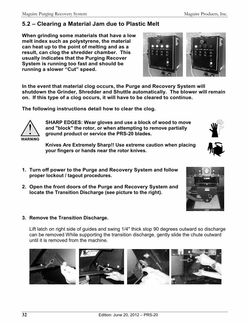
5.2 – Clearing a Material Jam due to Plastic Melt When grinding some materials that have a low melt index such as polystyrene, the material can heat up to the point of melting and as a result, can clog the shredder chamber. This usually indicates that the Purging Recover System is running too fast and should be running a slower “Cut” speed.
In the event that material clog occurs, the Purge and Recovery System will shutdown the Grinder, Shredder and Shuttle automatically. The blower will remain on. If this type of a clog occurs, it will have to be cleared to continue. The following instructions detail how to clear the clog.
SHARP EDGES: Wear gloves and use a block of wood to move and "block" the rotor, or when attempting to remove partially ground product or service the PRS-20 blades. Knives Are Extremely Sharp!! Use extreme caution when placing your fingers or hands near the rotor knives.
1. Turn off power to the Purge and Recovery System and follow
proper lockout / tagout procedures.
2. Open the front doors of the Purge and Recovery System and locate the Transition Discharge (see picture to the right).
3. Remove the Transition Discharge. Lift latch on right side of guides and swing 1/4" thick stop 90 degrees outward so discharge can be removed While supporting the transition discharge, gently slide the chute outward until it is removed from the machine.
Maguire Products, Inc.
Edition: June 20, 2012 – PRS-20 33
Maguire Purging Recovery System
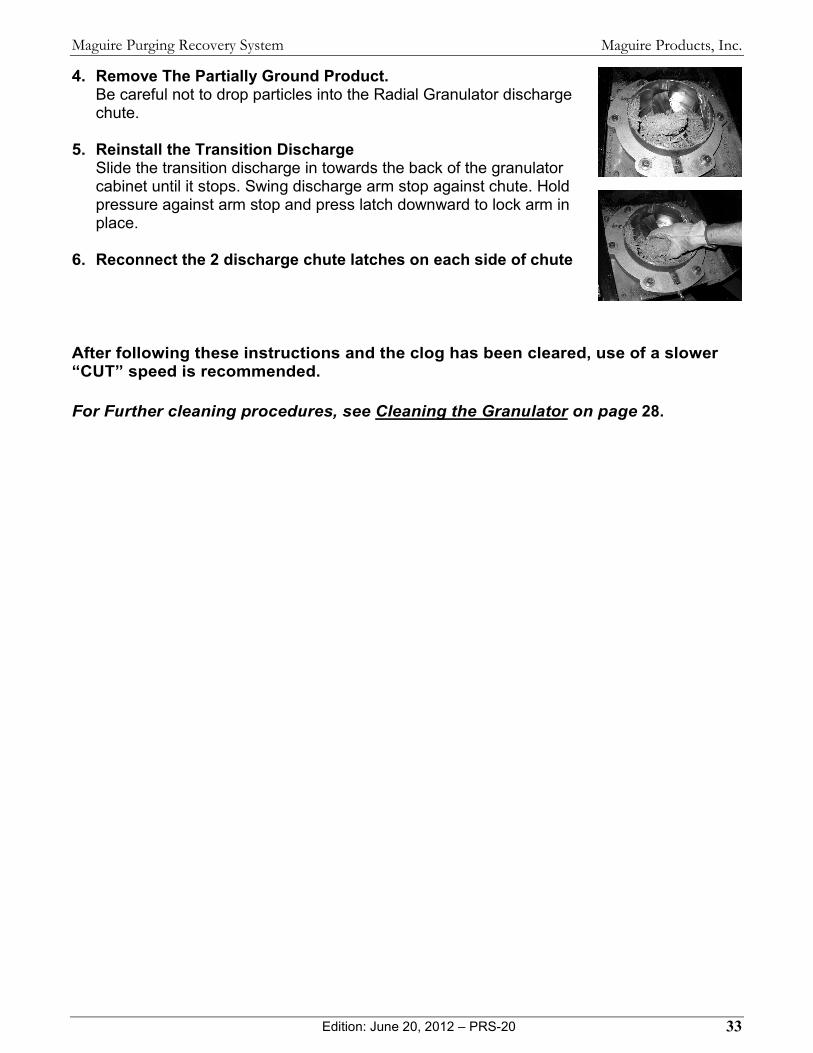
4. Remove The Partially Ground Product. Be careful not to drop particles into the Radial Granulator discharge chute.
5. Reinstall the Transition Discharge Slide the transition discharge in towards the back of the granulator cabinet until it stops. Swing discharge arm stop against chute. Hold pressure against arm stop and press latch downward to lock arm in place.
6. Reconnect the 2 discharge chute latches on each side of chute
After following these instructions and the clog has been cleared, use of a slower “CUT” speed is recommended. For Further cleaning procedures, see Cleaning the Granulator on page 28.
Maguire Products, Inc.
Edition: June 20, 2012 – PRS-20 34
Maguire Purging Recovery System
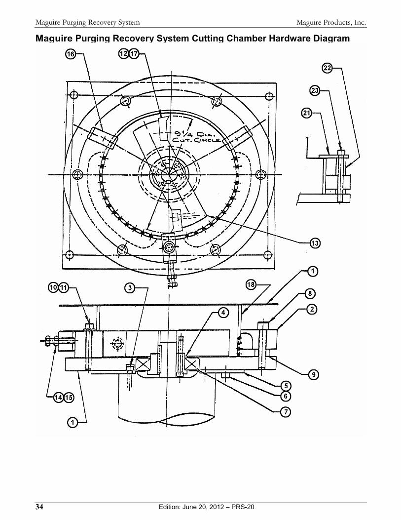
Maguire Purging Recovery System Cutting Chamber Hardware Diagram
Maguire Products, Inc.
Edition: June 20, 2012 – PRS-20 35
Maguire Purging Recovery System
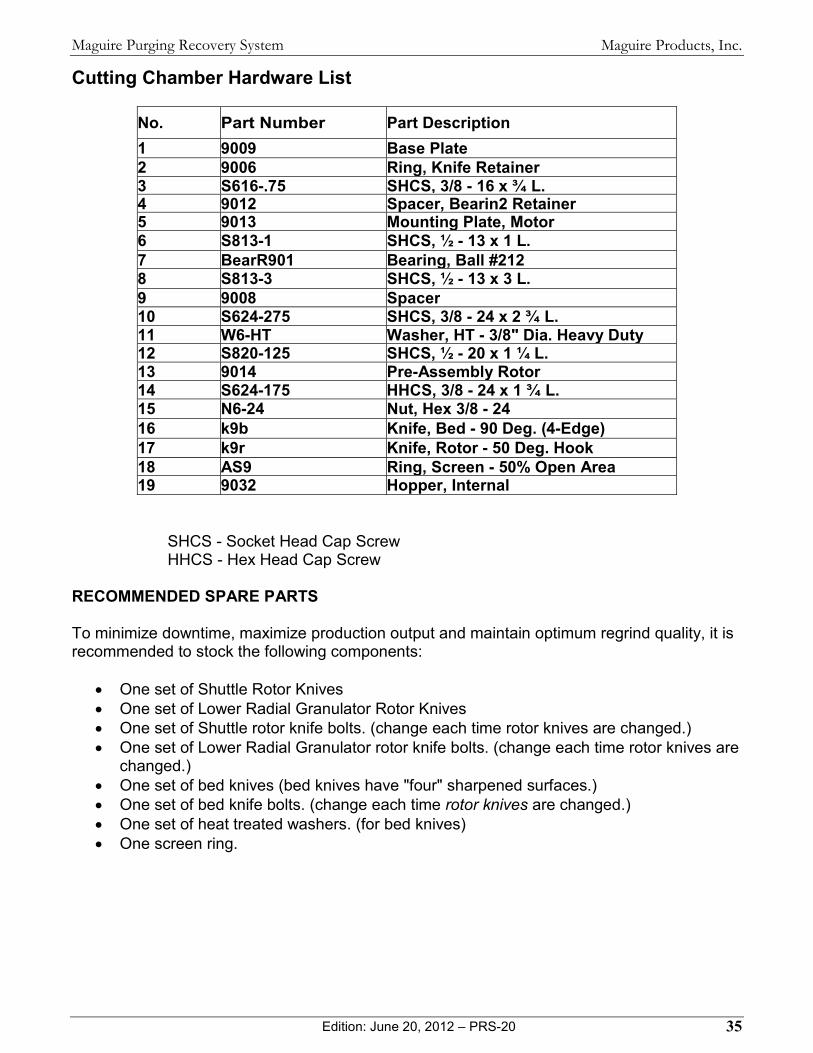
Cutting Chamber Hardware List
No. Part Number Part Description 1 9009 Base Plate 2 9006 Ring, Knife Retainer 3 S616-.75 SHCS, 3/8 - 16 x ¾ L. 4 9012 Spacer, Bearin2 Retainer 5 9013 Mounting Plate, Motor 6 S813-1 SHCS, ½ - 13 x 1 L. 7 BearR901 Bearing, Ball #212 8 S813-3 SHCS, ½ - 13 x 3 L. 9 9008 Spacer10 S624-275 SHCS, 3/8 - 24 x 2 ¾ L. 11 W6-HT Washer, HT - 3/8" Dia. Heavy Duty 12 S820-125 SHCS, ½ - 20 x 1 ¼ L. 13 9014 Pre-Assembly Rotor 14 S624-175 HHCS, 3/8 - 24 x 1 ¾ L. 15 N6-24 Nut, Hex 3/8 - 24 16 k9b Knife, Bed - 90 Deg. (4-Edge) 17 k9r Knife, Rotor - 50 Deg. Hook 18 AS9 Ring, Screen - 50% Open Area 19 9032 Hopper, Internal
SHCS - Socket Head Cap Screw HHCS - Hex Head Cap Screw
RECOMMENDED SPARE PARTS To minimize downtime, maximize production output and maintain optimum regrind quality, it is recommended to stock the following components:
• One set of Shuttle Rotor Knives • One set of Lower Radial Granulator Rotor Knives • One set of Shuttle rotor knife bolts. (change each time rotor knives are changed.) • One set of Lower Radial Granulator rotor knife bolts. (change each time rotor knives are
changed.) • One set of bed knives (bed knives have "four" sharpened surfaces.) • One set of bed knife bolts. (change each time rotor knives are changed.) • One set of heat treated washers. (for bed knives) • One screen ring.

Maguire Products, Inc.
Edition: June 20, 2012 – PRS-20 36
Maguire Purging Recovery System
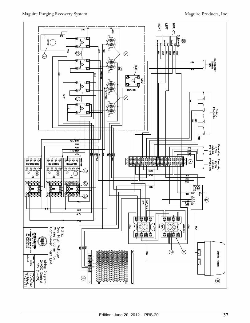
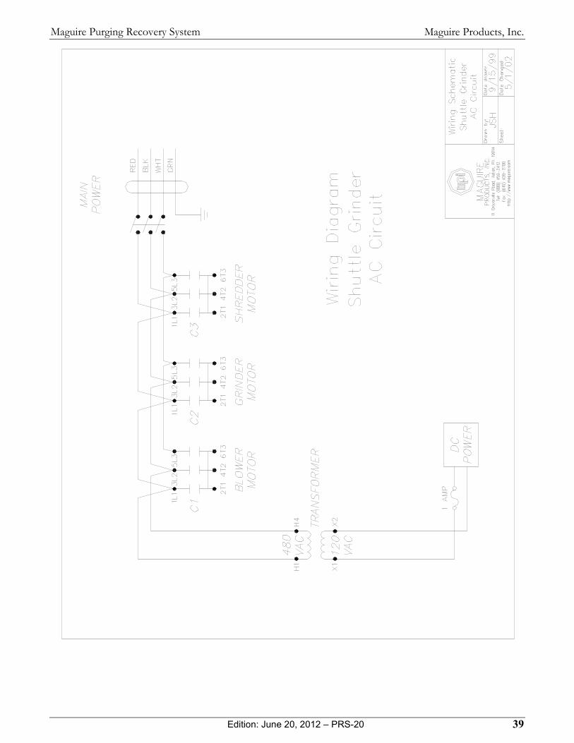
Maguire Purging Recovery System Wiring Diagrams
Maguire Products, Inc.
Edition: June 20, 2012 – PRS-20 37
Maguire Purging Recovery System

Maguire Products, Inc.
Edition: June 20, 2012 – PRS-20 38
Maguire Purging Recovery System
Maguire Products, Inc.
Edition: June 20, 2012 – PRS-20 39
Maguire Purging Recovery System

Maguire Products, Inc.
Edition: June 20, 2012 – PRS-20 40
Maguire Purging Recovery System

Maguire Products, Inc.
Edition: June 20, 2012 – PRS-20 41
Maguire Purging Recovery System
Maguire Products, Inc.
Edition: June 20, 2012 – PRS-20 42
Maguire Purging Recovery System

Maguire Products, Inc.
Edition: June 20, 2012 – PRS-20 43
Maguire Purging Recovery System

Maguire Products, Inc.
Edition: June 20, 2012 – PRS-20 44
Maguire Purging Recovery System
Maguire Products, Inc.
Edition: June 20, 2012 – PRS-20 45
Maguire Purging Recovery System
6 – General Information Our Design Philosophy
While we do have competitors, our equipment is different. Here is why. When we design equipment, we have FIVE objectives. All are important, but not all are obvious. In their order of importance they are: 1. FUNCTION:
This is very simple; the customer has certain requirements, and we must meet these Requirements. This is the most obvious consideration, the first consideration, and the one consideration that can most easily be tested and compared.
2. RELIABILITY:
This is not so easy to test. Time and experience is the only way to be sure equipment will last a long time, require little or no maintenance, and provide maximum "up" time. The true cost of equipment can be much higher when maintenance and lost production time are added in.
3. SERVICEABILITY:
When it breaks, how easily can it be serviced. Can your employees do it, do it quickly, and do it right? Is skilled and costly outside service required? Are parts readily available? How much time will it take to get it running again.
4. EASE OF USE:
What percentage of your employees will be able to run this equipment. All of them? Only the best of them? Maybe only the engineers in the office? How about the night shift? Ease of use is very important. Production suffers when equipment is difficult to understand and operate.
5. PRICE:
Very important. Especially to us. Customers often consider this the most important item .... and it is easy to compare.
Our competitors often get number 1 and 5 right, "Function" and "Price". On the other hand "Reliability", "Serviceability", and "Ease of use" are difficult to measure, hard to value, and hard to use as selling points. They are also much more difficult features to achieve in the design. We take these three objectives very seriously, incorporating them into product from the very beginning of the design process. Lost production time, while difficult to predict, is very expensive. For that reason we place these design goals ahead of cost. In the long run our customers are better served by this philosophy and, therefore, so are we.

Maguire Products, Inc.
Edition: June 20, 2012 – PRS-20 46
Maguire Purging Recovery System
Warranty
MAGUIRE PRODUCTS offers THE MOST COMPREHENSIVE WARRANTY in the plastics auxiliary equipment industry. We warrant each MAGUIRE PRS-20 manufactured by us to be free from defects in material and workmanship under normal use and service; excluding only those items listed below as 'excluded items'; our obligation under this warranty being limited to making good at our factory any PRS-20 which shall, within FIVE (5) YEARS after delivery to the original purchaser, be RETURNED intact to us, transportation charges PREPAID, and which our examination shall disclose to our satisfaction to have been thus defective; this warranty being expressly in lieu of all other warranties expressed or implied and of all other obligations or liabilities on our part, and MAGUIRE PRODUCTS neither assumes nor authorizes any other persons to assume for it any other liability in connection with the sale of its Granulators. This warranty shall not apply to equipment repaired or altered outside MAGUIRE PRODUCTS INC. factory, unless such repair or alteration was, in our judgment, not responsible for the failure; nor which has been subject to misuse, negligence or accident, incorrect wiring by others, or installation or use not in accord with instructions furnished by Maguire Products, Inc. Our liability under this warranty will extend only to equipment that is returned to our factory in Aston, Pennsylvania, PREPAID. Please note that we always strive to satisfy our customers in whatever manner is deemed most expedient to overcome any problems they may have in connection with our equipment. EXCLUDED ITEMS: REPLACEMENT PARTS such as rotor knives, bed knives, belts, their associated hardware and removable screen ring or other "wear surfaces" etc. DISCLAIMER - PRODUCTION of FAULTY PRODUCT We will only be responsible to correct, repair, replace, or accept return for full refund, our equipment if it fails to perform as designed, or we have inadvertently misrepresented our equipment for your application. If for any reason this disclaimer is not acceptable, we will accept return of the equipment for full refund, including freight costs both ways.

Maguire Products, Inc.
Edition: June 20, 2012 – PRS-20 47
Maguire Purging Recovery System
6.8 - Technical Support and Contact Information
Maguire Products Inc. 11 Crozerville Road Aston, PA 19014 Tel: 610.459.4300 Fax: 610.459.2700 Email: [email protected] Web: www.maguire.com Maguire Europe Tame Park Tamworth Staffordshire B775DY UK Tel: + 44 1827 265 850 Fax: + 44 1827 265 855 Email: [email protected] Maguire Products Asia PTE LTD Main Office 15 Changi North Street 1 #01-15, I-Lofts Singapore 498765 Tel: 65 6848-7117 Fax: 65 6542-8577 E-mail: [email protected]
Maguire Italy Via Zancanaro 40 35020 Vigorovea (PD) Tel: +39 049 970 54 29 Fax: +39 049 971 18 38 Email: [email protected]