siemens digital industries software five best practices ... · an approximated curve to create a...
TRANSCRIPT

solidedge.siemens.com
Siemens Digital Industries Software
Five best practices for mastering surface modeling
2
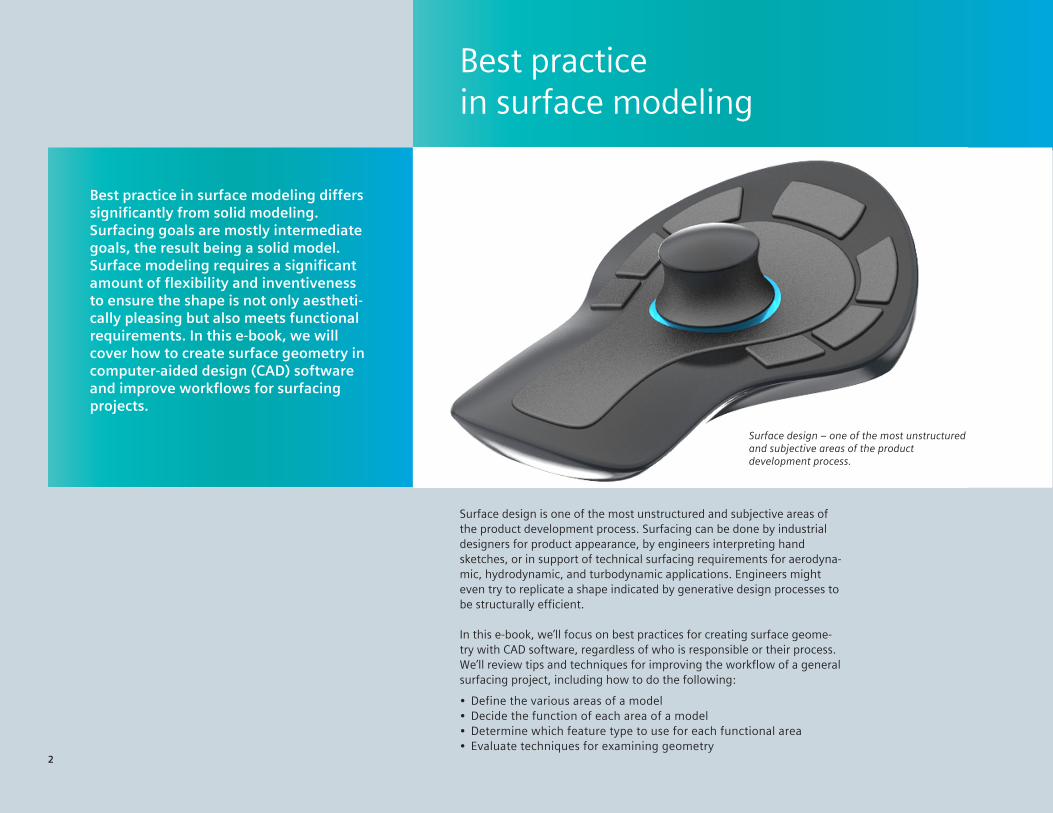
Surface design is one of the most unstructured and subjective areas of the product development process. Surfacing can be done by industrial designers for product appearance, by engineers interpreting hand sketches, or in support of technical surfacing requirements for aerodyna-mic, hydrodynamic, and turbodynamic applications. Engineers might even try to replicate a shape indicated by generative design processes to be structurally efficient.
In this e-book, we’ll focus on best practices for creating surface geome-try with CAD software, regardless of who is responsible or their process. We’ll review tips and techniques for improving the workflow of a general surfacing project, including how to do the following:
• Define the various areas of a model• Decide the function of each area of a model• Determine which feature type to use for each functional area• Evaluate techniques for examining geometry
Best practice in surface modeling
2
Best practice in surface modeling differs significantly from solid modeling. Surfacing goals are mostly intermediate goals, the result being a solid model. Surface modeling requires a significant amount of flexibility and inventiveness to ensure the shape is not only aestheti-cally pleasing but also meets functional requirements. In this e-book, we will cover how to create surface geometry in computer-aided design (CAD) software and improve workflows for surfacing projects.
Surface design – one of the most unstructured and subjective areas of the product development process.

3
In this e-book, we’ll focus on surface creation using non-uniform rational B-splines (NURBS). NURBS surfaces create various patches of different mathematical/topologi-cal types. When using solid modeling, you create enough faces in a single feature to completely enclose a volume. In surface modeling, you break that down to make a single face or surface body (a merged group of faces) until you have enough surfaces to fully enclose a volume or make a solid.
Surfacing functions, especially interpolated surfaces, work best when creating four-sided patches. With curves in two directions, that is the way the underlying structure lies best. The harder you try to resist four-sided patches, the more difficult your task will be, with a few exceptions. When creating a three- or two-sided patch, there is either one or two edges that are zero length. This condition is known as a degeneracy, and even if it works when you create it, it can cause problems with your model in downs-tream operations such as fillet, shell, offset and others.
Spotlight on Solid Edge
Solid Edge® software is industry-leading 3D design software that is equally adept at handling mechanical as well as stylized mode-ling. Solid Edge is based on Parasolid® software, which uses NURBS technology to establish the math for the faces of 3D solids. Solid Edge is extremely capable with complex shapes, geometric evaluation and shape analysis as well as solid and surface body manipulation and management.
3
Best practice No. 1: Use four-sided patches for surface creation
The original four-sided patch is trimmed and shaped by other features until it is nearly unrecognizable.

44
Following best practices is especially important when working with history-based software as it helps avoid unnecessary rebuilds or features that take too long to rebuild. When working on a model, try not to fluctuate between surfaces and solids; there should be a point in the history tree where you transition from one to the other. Hybrid methods, in which surface features are used to edit a solid, are sufficient. However, avoid converting a single body back and forth between the two.
You may find that with certain types of repairs on impor-ted data, you begin with solid data and later need to convert it to surfaces, then back to solids. This is an excep-tion to the rule and it is often necessary to eliminate the bad geometry in the imported model and replace it with newly created or edited geometry.
In most situations, your goal is to create a finished solid body. Surface bodies are most often an intermediate step on the way to creating a solid body.
Best practice No. 2: Make a single transition between surfaces and solids
The transition from surface to solid should be a one-time, one-way trip
4

5
Best practice No. 3: Overbuild surfaces and trim to fit
Sometimes you’ll be tempted to fill a gap in a model with a surface that exactly fits, or perhaps you need some-thing a certain size and are tempted to make the surface just that size. One of the nice things about NURBS and the boundary representation (BREP) system is that it works well with trimmed surfaces. This allows you to create a surface in any size or shape, then trim it to the precise size or shape you need.
As a best practice, you should create the surface to the size and shape that ensures the best quality surface before you trim it to the size and shape that fits. For example, if you have a triangular gap, you don’t have to create a degenerate surface to fit exactly. You can create something that is four-sided, ensuring a good surface while still fitting the rest of the requirements, and trim the four-sided patch to a three-sided patch with a non-degenerate mesh. Another option, instead of using an approximated curve to create a surface up to another complex surface, is to simply create the surface larger than it needs to be and use the complex surface to trim the new surface for an exact fit. Trimming is almost always preferable to using a projected curve or curve on a surface to create another surface.
Build surfaces, such as the red BlueSurf pictured above, are larger than necessary and trimmed to fit the desired area. This helps you avoid awkward shapes to create the best surfaces.
6
Best practice No. 4: Complete surface features before joining
6
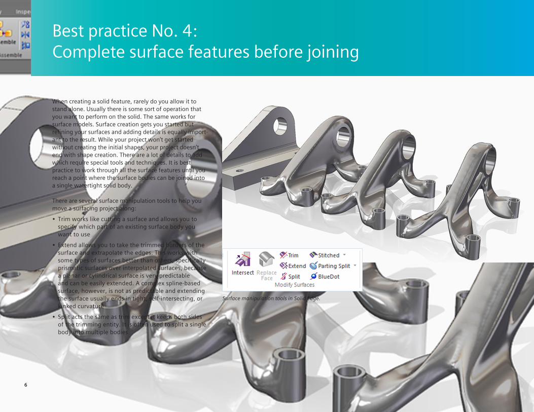
When creating a solid feature, rarely do you allow it to stand alone. Usually there is some sort of operation that you want to perform on the solid. The same works for surface models. Surface creation gets you started but refining your surfaces and adding details is equally import-ant to the result. While your project won’t get started without creating the initial shapes, your project doesn’t end with shape creation. There are a lot of details to add which require special tools and techniques. It is best practice to work through all the surface features until you reach a point where the surface bodies can be joined into a single watertight solid body.
There are several surface manipulation tools to help you move a surfacing project along:
• Trim works like cutting a surface and allows you to specify which part of an existing surface body you want to use
• Extend allows you to take the trimmed borders of the surface and extrapolate the edges. This works with some types of surfaces better than others, specifically prismatic surfaces over interpolated surfaces, because a planar or cylindrical surface is very predictable and can be easily extended. A complex spline-based surface, however, is not as predictable and extending the surface usually ends in tight, self-intersecting, or kinked curvature
• Split acts the same as trim except it keeps both sides of the trimming entity. It is often used to split a single body into multiple bodies
Surface manipulation tools in Solid Edge.

7
Controlling multiple solid and construction (surface) bodies is an important part of any modeling project. Using the Master Model technique, the user creates the outer shape of the model in a single part and then distributes that shape to individual parts. The compari-son is often made to an automobile design where the shape is created using surfaces then is split into bodies to create the front door, back door, hood, roof, front fender, and so on. From there, you continue making the model in each of the individual parts. You can even use this technique to align features within the bodies that become individual parts, such as pins, mounting or screw bosses.
The parts are brought back together in an assembly. Because all the origins of the original bodies were the same in the original part, the origins align when the parts are put back together in the assembly.
This type of design introduces external references, but they are the kind of references that can be easily controlled. Changes to the original Master Model can propagate through the bodies to the published parts and into the assembly. This works for both large top-level changes and for smaller detail changes that happen at the individual part level. It can even be used if the number of parts created from the Master Model change from the original.
Best practice No. 5: Use the Master Model technique
Using the Master Model technique, the user creates a single outer shape first, then distributes that shape to individual parts.

8
BlueSurfBueSurf allows you to select a single section and a single guide curve, enables you to cap the ends, allows you to create a closed loop (like an ox yoke shape), transition from a closed-loop sketch to open loop, or add sections semi-automatically. Unlike other CAD tools, BlueSurf can loft from a closed profile to a line.
BlueDotBlueSurf also enables the option to use BlueDots or Pierce Points to connect crossing curves in automati-cally added sketches. Solid Edge BlueSurf gets its name from the BlueDot, which, as the name implies, is a blue dot. In Solid Edge there is an option to use BlueDots in your Curve Connectivity settings. This means that when you use the Insert Sketch Step, Solid Edge will automat-ically add a BlueDot between sketches that intersect.
CurvesCurves and edges are important when creating surface features. Solid Edge contains a toolset of curves to help you create nice surfaces. These include Keypoint curves, 3D sketches, projected and wrapped curves, intersec-tion curves, helical and cross curves, contour (curve on surface), isoclines and derived curves.
Surface manipulation toolsSolid Edge contains powerful surface manipulation tools, such as Redefine and Intersect.
RedefineThe Redefine feature allows you to take multiple faces broken up by edges and create a single face in their place or eliminate the edges in the middle of a surface that you want to be a single continuous face. This feature works on surface or solid bodies.
8
Solid Edge handles any situation you will find in your surfacing projects with powerful and stable features. Solid Edge surfacing can be done in either ordered or synchronous mode, but complex interpolated shapes should be handled in ordered mode. One of the unique capabilities of Solid Edge is to use synchronous mode for sketches and ordered mode for actual features. This enables live editing; the surface changes as you drag even spline sketches.
Solid Edge retains all the power of synchronous mode when working with prismatic surfaces. You can also use synchronous tools to move or position solid or surface bodies wit-hin a model.
Surfacing in Solid Edge
8
Solid Edge contains the following key tools to support surfacing work:

9
IntersectIntersect saves significant time by combining and automat-ing several existing features. Intersect is a fancy trim tool that will split solids, trim and knit surfaces and divide regions into bodies. You can trim, extend and stitch sur-faces into solid bodies with this tool.
Evaluation toolsEvaluation tools help verify that any geometry you create fulfills basic modeling requirements, such as if faces are tangent or curvature is continuous across an edge, if you have any open edges in a surface body or what the model looks like across a plane of symmetry.
Zebra StripesYou can get more analytical by using the Zebra Stripes function. The smoothness of the lines in the reflection show you if there are any discontinuities in the curvature.
Curvature ShadingCurvature Shading can help you see if you have points with a very small radius or places where the model is almost flat.
Surface visualization options Surface visualization options are also available as you work with new features. For example, you can view a bounded surface feature with the surface mesh and the associated curvature comb displayed at the same time.
Reflective plane Reflective plane enables you to see the model reflected across a plane of symmetry. This option enables you to see the other half of the model as a display as you work. Once one half of the model is completed, you can then mirror the geometry.
9
Solid Edge contains the following key tools to support surfacing work:

10
The right approach can significantly change depen-ding on the situation and your goals. Surfacing work is often less defined than most solid modeling. However, if other people are going to work with your finished data, and the skill level of those users is not necessarily clear, it is best to approach tasks with the simplest methods and even provide some comments on your thoughts and reasoning within the CAD data itself.
Following the guidelines in this e-book, keep these best practices in mind:
• Surfacing functions, especially interpolated surfaces, work best when you are trying to create four-sided patches
• When working on a model, try not to fluctuate between surfaces and solids
• Create surfaces in the size and shape that ensures the best quality, then trim to the size and shape that fits your model
• Complete your surface features first, then join the surface bodies together into a single watertight solid body
• Create the outer shape of the entire model in a single part and then distribute that shape to individual parts
• Pick a software tool that is flexible and easy-to-use while providing all the capabilities you need
Conclusion
10

11
Solid Edge: Everything you need for seamless surfacing Solid Edge is a portfolio of product development tools: mechanical and electrical design, simulation, manufacturing, technical publica-tions, data management and more. Solid Edge combines the speed and simplicity of direct modeling with the flexibility and control of parametric design – made possible with synchronous technology.
Solid Edge has everything you need in the surfacing realm. It is extremely capable with complex shapes, geometric evaluation and shape analysis as well as solid and surface body manipulation and management.
Learn more, or try it for freeLearn more about surfacing in Solid Edge: siemens.com/plm/surfacing
Try surfacing and all the amazing capabilities in Solid Edge, for free: siemens.com/plm/try-solid-edge
11

About Siemens Digital Industries SoftwareSiemens Digital Industries Software, a business unit of Siemens Digital Industries, is a leading global provider of software solutions to drive the digital transformation of industry, creating new opportunities for manufacturers to realize innovation. With headquarters in Plano, Texas, and over 140,000 customers worldwide, we work with companies of all sizes to transform the way ideas come to life, the way products are realized, and the way products and assets in operation are used and understood. For more information on our products and services, visit siemens.com/plm.
Headquarters: Americas: Europe: Asia-Pacific:
+1 972 987 3000 +1 314 264 8499 +44 (0) 1276 413200 +852 2230 3333
© 2019 Siemens. A list of relevant Siemens trademarks can be found here. Other trademarks belong to their respective owners. 78105-C3 8/19 A