siemens energy & automation - ubbpatricioconcha.ubb.cl/410213/compilacion_sistemas...siemens...
TRANSCRIPT

Siemens Energy & Automation
Contact Us
About Us Training Careers
Sales Offices News Support Search
Advanced Search
Energy &Automation Home Current Stock Quote: SI
Solutions CommunitiesAutomotiveCementChemicalFood & BeverageMachine ToolsMarineMESMetalsMiningOil & GasPharmaceuticalProduction MachinesPulp & PaperQualityOther Industries
Product CommunitiesAutomationCNCControlsDrivesElectric MotorsInstrumentation & AnalyticsMotion ControlPower DistributionProcess AutomationResidential Electrical
Services CommunitiesIndustrial ServicesIT Plant Services
LinksNEMA web siteKnowledge@EmorySiemens Racing
Home > Motors Community > Motor Product > NEMA Application Manual
NEMA Frames Application Manual
NEMA Frames Application Manual
Table of Contents
Sec. 1.1 NEMA Frame TEFC Motors 600 Volts and BelowProduct Range and Scope by Frames Series
79K
Sec. 1.2 Medallion™ TEFC Severe Duty Premium Efficiency Type RGZESD – 140 Through 440 Frames
30K
Sec. 2 Basic Motor Terminology and Theory 159K
Sec. 3 Sales Material and Brochures List Available online
Sec. 4 Dimension Print Index Page
Sec. 5.1 Frame Assignments 56K
Sec. 5.2 Speed Torque Curves 711K
Sec. 5.3 Insulation System 19K
Sec. 5.4 External Load Inertia Capability,Wk2 [lb-ft2] 21K
Sec. 5.5 Connection Diagrams 47K
Sec. 5.6 Temperature Rise Diagrams 13K
Sec. 6 Mechanical Data 960K
Sec. 7 Space Heaters & Thermal Protective Devices 117K
Sec. 8 Industry Standards 233K
http://www.sea.siemens.com/motors/product/mtnemaapmanual.html (1 de 2) [10-06-2005 17:34:50]

Siemens Energy & Automation
Bookmark This Page
Sec. 9 Standard, Complete and Noise Tests 110K
Sec. 10 Special Applications and Information 316K
©2005, Siemens Energy & Automation, Inc. Legal Notices / Privacy PolicyContact Us
http://www.sea.siemens.com/motors/product/mtnemaapmanual.html (2 de 2) [10-06-2005 17:34:50]
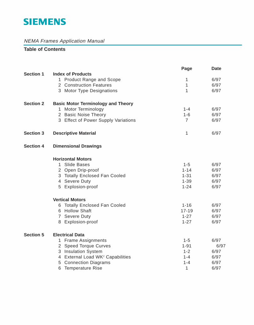
NEMA Frames Application Manual
Table of Contents
Page DateSection 1 Index of Products
1 Product Range and Scope 1 6/972 Construction Features 1 6/973 Motor Type Designations 1 6/97
Section 2 Basic Motor Terminology and Theory1 Motor Terminology 1-4 6/972 Basic Noise Theory 1-6 6/973 Effect of Power Supply Variations 7 6/97
Section 3 Descriptive Material 1 6/97
Section 4 Dimensional Drawings
Horizontal Motors1 Slide Bases 1-5 6/972 Open Drip-proof 1-14 6/973 Totally Enclosed Fan Cooled 1-31 6/974 Severe Duty 1-39 6/975 Explosion-proof 1-24 6/97
Vertical Motors6 Totally Enclosed Fan Cooled 1-16 6/976 Hollow Shaft 17-19 6/977 Severe Duty 1-27 6/978 Explosion-proof 1-27 6/97
Section 5 Electrical Data1 Frame Assignments 1-5 6/972 Speed Torque Curves 1-91 6/973 Insulation System 1-2 6/974 External Load WK2 Capabilities 1-4 6/975 Connection Diagrams 1-4 6/976 Temperature Rise 1 6/97
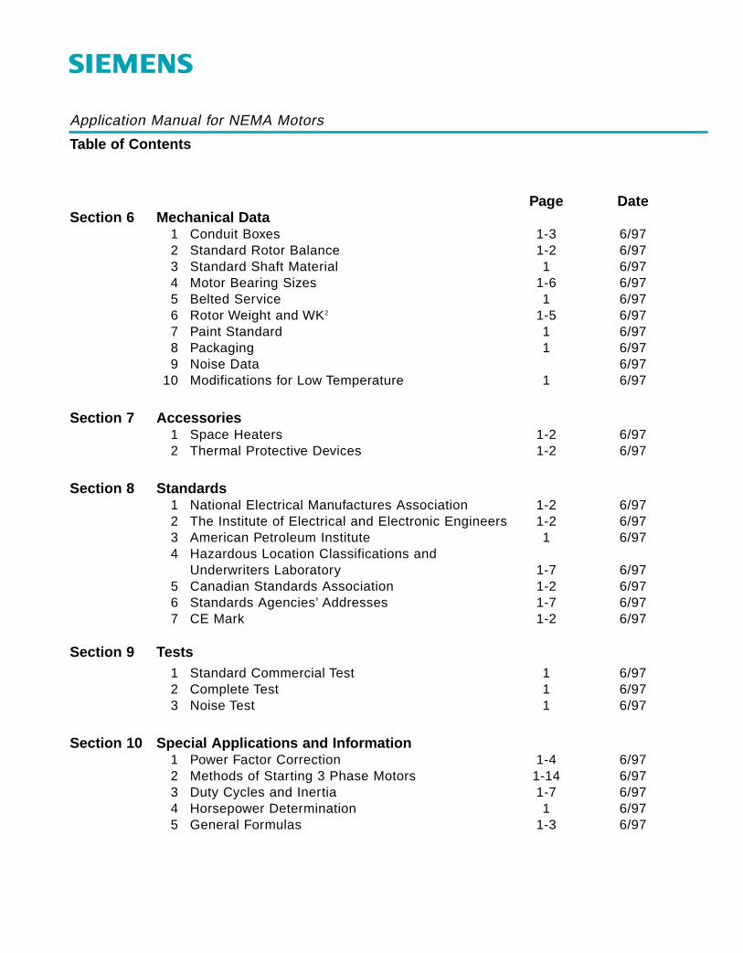
Application Manual for NEMA Motors
Table of Contents
Page DateSection 6 Mechanical Data
1 Conduit Boxes 1-3 6/972 Standard Rotor Balance 1-2 6/973 Standard Shaft Material 1 6/974 Motor Bearing Sizes 1-6 6/975 Belted Service 1 6/976 Rotor Weight and WK2 1-5 6/977 Paint Standard 1 6/978 Packaging 1 6/979 Noise Data 6/97
10 Modifications for Low Temperature 1 6/97
Section 7 Accessories1 Space Heaters 1-2 6/972 Thermal Protective Devices 1-2 6/97
Section 8 Standards1 National Electrical Manufactures Association 1-2 6/972 The Institute of Electrical and Electronic Engineers 1-2 6/973 American Petroleum Institute 1 6/974 Hazardous Location Classifications and
Underwriters Laboratory 1-7 6/975 Canadian Standards Association 1-2 6/976 Standards Agencies’ Addresses 1-7 6/977 CE Mark 1-2 6/97
Section 9 Tests1 Standard Commercial Test 1 6/972 Complete Test 1 6/973 Noise Test 1 6/97
Section 10 Special Applications and Information1 Power Factor Correction 1-4 6/972 Methods of Starting 3 Phase Motors 1-14 6/973 Duty Cycles and Inertia 1-7 6/974 Horsepower Determination 1 6/975 General Formulas 1-3 6/97

Application Manual for NEMA Motors
NEMA Frame TEFC Motors600 Volts and BelowProduct Range and Scope By Frames Series
SectionPartPageDate
1116/97
HP/Speed 3600 1800 1200 9001 - -
140-
140 -1801.5
2-
140-
180
3-
210
5-
180-
180-
210
7.5-
250
10-
210-
210-
250
15 -250
-250
-280
20-
280
25 -280
-280
-320
30-
320
40 -320
-360
50-
320-
360
60 -360
-400
75-
360-
400--
440--
100 400 400--
440--
125--
440--
150
200
250 S440
300
--
440--
S440 -
350 S440 S440-
--
--400 -
Exact division between frames is dependent on motorvoltage, service factor and efficiency options.
See Section 5, Part 1 and NEMA MG13 for further details,frame designations and enclosures.

Application Manual for NEMA Motors
Open Drip – ProofType RGE1 – 140 Through 400 FramesType RGE – 440 Frames
*Example: 440 Means 444T, 444TS, 445T, 445TS, 447T, 447TS, 449T OR 449TS
SectionPartPageDate
12112/00
Basic Frame Size* 140 180 210 250 280 320 360 400 440
Internal Bearing Protection None Rotating BearingCaps
Frame Material Steel Cast Iron
Bearing Bracket Material Cast Iron
Bearings See Section 6
Conduit Box Cover Gasket Material None Neoprene
Conduit Box Diagonally Split Yes
Hardware Corrosion Resistant Zinc Plated Hex Head
Conduit Box Material Steel Cast Iron
Eyebolt None Yes
Air Deflector Material Steel Plastic
Lead Terminals Yes
Lubrication Fittings Pipe Plugs – Inlet And Outlet
Nameplate Material Stainless Steel
Shaft Seal None
Voltage See Medallion Selection And Pricing Guide For Integral Horsepower AC Motors
Rotor Pressure Die Cast Aluminium With A Protective Coating On Outside Diameter
Insulation System Class F

Application Manual for NEMA Motors
Medallion™Standard TEFC & Premium Efficiency TEFCType RGZP – 140 Through 440 Frames
SectionPartPageDate
12212/00
Basic Frame Size* 140 180 210 250 280 320 360 400 440
Bearings See Section 6
Bearing Bracket Material
Conduit Box Cover GasketMaterial
Neoprene
Conduit Box Diagonally Split
Yes
Conduit Box Material
Conduit Box To FrameGasket Material
Neoprene
Condensation DrainCombination T Slot
Each Housing
Aluminum
*Example: 440 Means 444T, 444TS, 445T, 445TS, 447T, 447TS, 449T OR 449TS
Aluminum
Cast Iron
Neoprene
Hole
YesEyebolt Provisions For
Fan Material Locked and Keyed Plastic
PolypropyleneFan Cover Material Steel Cast Iron
Frame Material Cast Iron
Internal Bearing Protection None
Corrosion Resistant Zinc Plated Hex HeadHardware Corrosion Resistant Zinc Plated
Lead Terminals Yes
Cast Iron
StationaryBrg Caps
Pipe Plugs - Inlet and OutletLubrication Fittings None
Stainless SteelNameplate Material Aluminum
YesShaft Seal None
Voltage See Medallion Selection & Pricing Guide for Integral Horsepower AC Motors
Rotor Pressure Die Cast Aluminum with a Protective Coating on Outside Diameter
Insulation System Class F
Steel
None
Application Manual for NEMA Motors
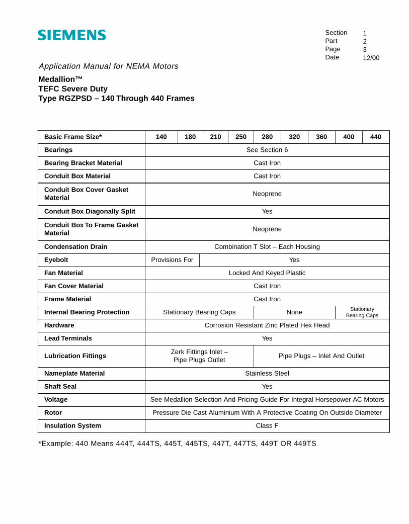
Medallion™TEFC Severe DutyType RGZPSD – 140 Through 440 Frames
SectionPartPageDate
12312/00
Basic Frame Size* 140 180 210 250 280 320 360 400 440
Bearings See Section 6
Bearing Bracket Material Cast Iron
Conduit Box Material Cast Iron
Conduit Box Cover GasketMaterial
Neoprene
Conduit Box Diagonally Split Yes
Conduit Box To Frame GasketMaterial
Neoprene
Condensation Drain Combination T Slot – Each Housing
Eyebolt Provisions For Yes
Fan Material Locked And Keyed Plastic
Internal Bearing Protection Stationary Bearing Caps StationaryBearing CapsNone
Fan Cover Material Cast Iron
Hardware Corrosion Resistant Zinc Plated Hex Head
Frame Material Cast Iron
Lubrication FittingsZerk Fittings Inlet – Pipe Plugs Outlet
Pipe Plugs – Inlet And Outlet
Nameplate Material Stainless Steel
Lead Terminals Yes
Shaft Seal Yes
Rotor Pressure Die Cast Aluminium With A Protective Coating On Outside Diameter
Voltage See Medallion Selection And Pricing Guide For Integral Horsepower AC Motors
Insulation System Class F
*Example: 440 Means 444T, 444TS, 445T, 445TS, 447T, 447TS, 449T OR 449TS

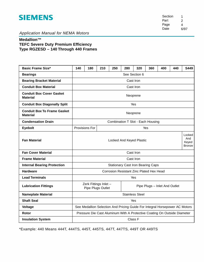
Application Manual for NEMA Motors
Medallion™TEFC Severe Duty Premium EfficiencyType RGZESD – 140 Through 440 Frames
SectionPartPageDate
1246/97
Bearings See Section 6
Basic Frame Size* 140 180 210 250 280 320 360 400 440 S449
Eyebolt Provisions For Yes
Bearing Bracket Material Cast Iron
Conduit Box Material Cast Iron
Conduit Box Cover GasketMaterial
Neoprene
Conduit Box Diagonally Split Yes
Conduit Box To Frame GasketMaterial
Neoprene
Condensation Drain Combination T Slot - Each Housing
Fan Material Locked And Keyed Plastic
LockedAnd
KeyedBronze
Fan Cover Material Cast Iron
Lubrication FittingsZerk Fittings Inlet – Pipe Plugs Outlet
Pipe Plugs – Inlet And Outlet
Frame Material Cast Iron
Internal Bearing Protection Stationary Cast Iron Bearing Caps
Hardware Corrosion Resistant Zinc Plated Hex Head
Lead Terminals Yes
Nameplate Material Stainless Steel
Shaft Seal Yes
Rotor Pressure Die Cast Aluminum With A Protective Coating On Outside Diameter
Voltage See Medallion Selection And Pricing Guide For Integral Horsepower AC Motors
Insulation System Class F
*Example: 440 Means 444T, 444TS, 445T, 445TS, 447T, 447TS, 449T OR 449TS

Application Manual for NEMA Motors
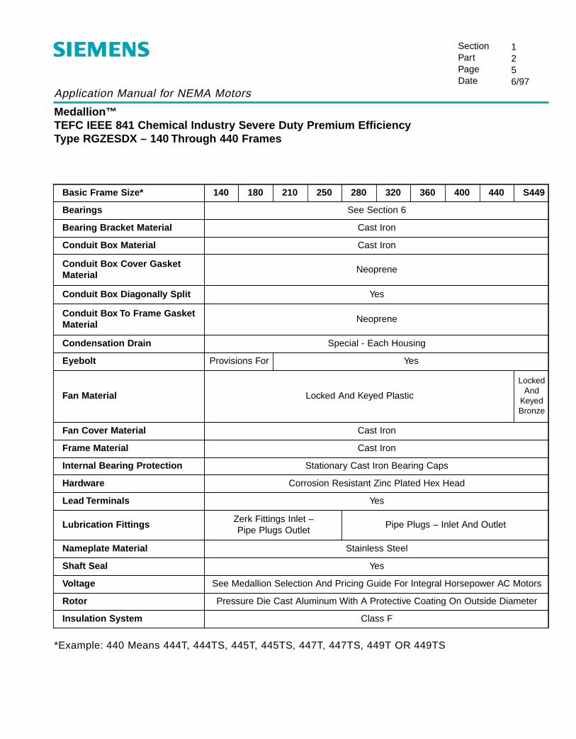
Medallion™TEFC IEEE 841 Chemical Industry Severe Duty Premium EfficiencyType RGZESDX – 140 Through 440 Frames
SectionPartPageDate
1256/97
*Example: 440 Means 444T, 444TS, 445T, 445TS, 447T, 447TS, 449T OR 449TS
Bearings See Section 6
Bearing Bracket Material Cast Iron
Conduit Box Material Cast Iron
Conduit Box Cover GasketMaterial
Neoprene
Conduit Box Diagonally Split Yes
Conduit Box To Frame GasketMaterial
Basic Frame Size* 140 180 210 250 280 320 360 400 440 S449
Eyebolt Provisions For
Fan Cover Material
Yes
Cast Iron
Frame Material Cast Iron
Internal Bearing Protection Stationary Cast Iron Bearing Caps
Hardware Corrosion Resistant Zinc Plated Hex Head
Neoprene
Condensation Drain Special - Each Housing
Fan Material Locked And Keyed Plastic
Lubrication FittingsZerk Fittings Inlet – Pipe Plugs Outlet
Shaft Seal Yes
Rotor
Pipe Plugs – Inlet And Outlet
Pressure Die Cast Aluminum With A Protective Coating On Outside Diameter
Voltage
LockedAnd
KeyedBronze
Lead Terminals Yes
Nameplate Material
See Medallion Selection And Pricing Guide For Integral Horsepower AC Motors
Insulation System Class F
Stainless Steel

Application Manual for NEMA Motors
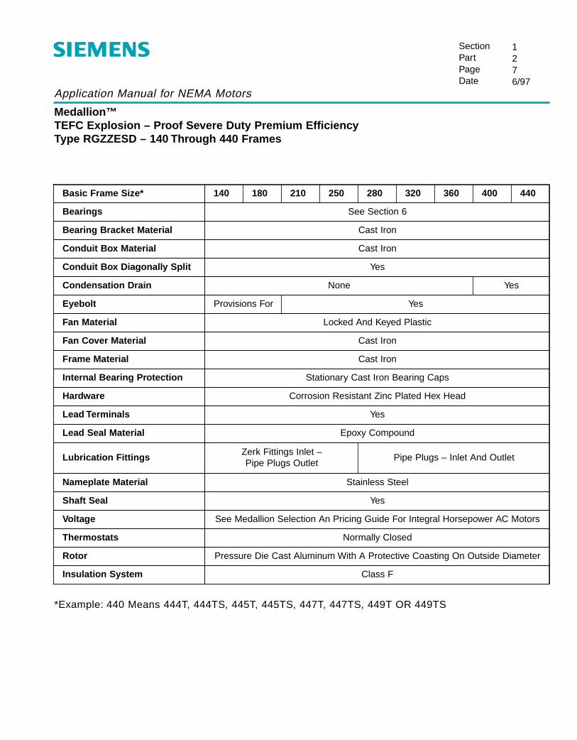
Medallion™TEFC Explosion – Proof Severe Duty Premium EfficiencyType RGZZESD – 140 Through 440 Frames
SectionPartPageDate
1276/97
*Example: 440 Means 444T, 444TS, 445T, 445TS, 447T, 447TS, 449T OR 449TS
Basic Frame Size* 140 180 210 250 280 320 360 400 440
Bearings See Section 6
Bearing Bracket Material Cast Iron
Conduit Box Material Cast Iron
Conduit Box Diagonally Split Yes
Condensation Drain None
Eyebolt Provisions For
Fan Material
Yes
Locked And Keyed Plastic
Fan Cover Material Cast Iron
Frame Material Cast Iron
Internal Bearing Protection
Lubrication FittingsZerk Fittings Inlet –Pipe Plugs Outlet
Shaft Seal Yes
Thermostats
Pipe Plugs – Inlet And Outlet
Yes
Stationary Cast Iron Bearing Caps
Hardware Corrosion Resistant Zinc Plated Hex Head
Lead Terminals Yes
Lead Seal Material Epoxy Compound
Nameplate Material Stainless Steel
Normally Closed
Voltage See Medallion Selection An Pricing Guide For Integral Horsepower AC Motors
Insulation System Class F
Rotor Pressure Die Cast Aluminum With A Protective Coasting On Outside Diameter

NEMA Frames Application Manual
Motor Type Designations
SectionPartPageDate
13112/00
Basic Design and Mechanical Features
RG - Open Drip-Proof (ODP)RGZ - Totally Enclosed Fan Cooled (TEFC)
RGZZ - TEFC Explosion-proof and/or Dust Ignition proof
Electrical Features
E - Premium EfficiencyP - Epact EfficiencyT - NEMA Design C, High Starting Torque, Low Slip
Special Duty, Service or Configuration
SD - Severe DutyF - Flange, Normally NEMA C or D Flange, Horizontal Mounted,
Examples: RGF, RGZF.V - Vertical, Normally Round Frame, Mounted Vertical by Flange
(NEMA C, D or P), Examples: RGV, RGZV, RGZZV, etc.IL - In-Line Pump, Vertical, Round Frame, P Flange, TEFC or
Explosion-proof, RGZV-IL, etc.
Application Manual for NEMA Motors
Medallion™TEFC Severe Duty Premium EfficiencyType RGZESD – 140 Through 440 Frames
SectionPartPageDate
1246/97
Bearings See Section 6
Basic Frame Size* 140 180 210 250 280 320 360 400 440 S449
Eyebolt Provisions For Yes
Bearing Bracket Material Cast Iron
Conduit Box Material Cast Iron
Conduit Box Cover GasketMaterial
Neoprene
Conduit Box Diagonally Split Yes
Conduit Box To Frame GasketMaterial
Neoprene
Condensation Drain Combination T Slot - Each Housing
Fan Material Locked And Keyed Plastic
LockedAnd
KeyedBronze
Fan Cover Material Cast Iron
Lubrication FittingsZerk Fittings Inlet – Pipe Plugs Outlet
Pipe Plugs – Inlet And Outlet
Frame Material Cast Iron
Internal Bearing Protection Stationary Cast Iron Bearing Caps
Hardware Corrosion Resistant Zinc Plated Hex Head
Lead Terminals Yes
Nameplate Material Stainless Steel
Shaft Seal Yes
Rotor Pressure Die Cast Aluminum With A Protective Coating On Outside Diameter
Voltage See Medallion Selection And Pricing Guide For Integral Horsepower AC Motors
Insulation System Class F
*Example: 440 Means 444T, 444TS, 445T, 445TS, 447T, 447TS, 449T OR 449TS
Application Manual for NEMA Motors
Medallion™TEFC IEEE 841 Chemical Industry Severe Duty Premium EfficiencyType RGZESDX – 140 Through 440 Frames
SectionPartPageDate
1256/97
*Example: 440 Means 444T, 444TS, 445T, 445TS, 447T, 447TS, 449T OR 449TS
Bearings See Section 6
Bearing Bracket Material Cast Iron
Conduit Box Material Cast Iron
Conduit Box Cover GasketMaterial
Neoprene
Conduit Box Diagonally Split Yes
Conduit Box To Frame GasketMaterial
Basic Frame Size* 140 180 210 250 280 320 360 400 440 S449
Eyebolt Provisions For
Fan Cover Material
Yes
Cast Iron
Frame Material Cast Iron
Internal Bearing Protection Stationary Cast Iron Bearing Caps
Hardware Corrosion Resistant Zinc Plated Hex Head
Neoprene
Condensation Drain Special - Each Housing
Fan Material Locked And Keyed Plastic
Lubrication FittingsZerk Fittings Inlet – Pipe Plugs Outlet
Shaft Seal Yes
Rotor
Pipe Plugs – Inlet And Outlet
Pressure Die Cast Aluminum With A Protective Coating On Outside Diameter
Voltage
LockedAnd
KeyedBronze
Lead Terminals Yes
Nameplate Material
See Medallion Selection And Pricing Guide For Integral Horsepower AC Motors
Insulation System Class F
Stainless Steel
Application Manual for NEMA Motors
Medallion™TEFC Explosion – Proof Severe Duty Premium EfficiencyType RGZZESD – 140 Through 440 Frames
SectionPartPageDate
1276/97
*Example: 440 Means 444T, 444TS, 445T, 445TS, 447T, 447TS, 449T OR 449TS
Basic Frame Size* 140 180 210 250 280 320 360 400 440
Bearings See Section 6
Bearing Bracket Material Cast Iron
Conduit Box Material Cast Iron
Conduit Box Diagonally Split Yes
Condensation Drain None
Eyebolt Provisions For
Fan Material
Yes
Locked And Keyed Plastic
Fan Cover Material Cast Iron
Frame Material Cast Iron
Internal Bearing Protection
Lubrication FittingsZerk Fittings Inlet –Pipe Plugs Outlet
Shaft Seal Yes
Thermostats
Pipe Plugs – Inlet And Outlet
Yes
Stationary Cast Iron Bearing Caps
Hardware Corrosion Resistant Zinc Plated Hex Head
Lead Terminals Yes
Lead Seal Material Epoxy Compound
Nameplate Material Stainless Steel
Normally Closed
Voltage See Medallion Selection An Pricing Guide For Integral Horsepower AC Motors
Insulation System Class F
Rotor Pressure Die Cast Aluminum With A Protective Coasting On Outside Diameter
NEMA Frames Application Manual
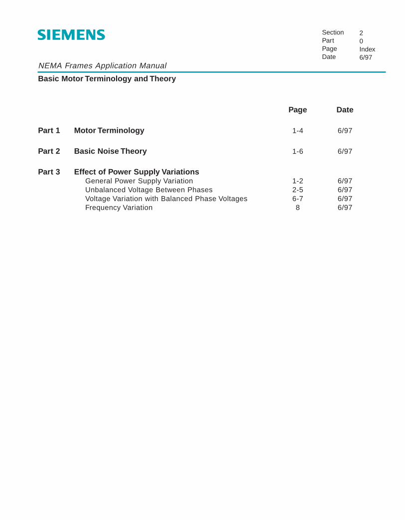
Basic Motor Terminology and Theory
SectionPartPageDate
20Index6/97
Page Date
Part 1 Motor Terminology 1-4 6/97
Part 2 Basic Noise Theory 1-6 6/97
Part 3 Effect of Power Supply VariationsGeneral Power Supply Variation 1-2 6/97Unbalanced Voltage Between Phases 2-5 6/97Voltage Variation with Balanced Phase Voltages 6-7 6/97Frequency Variation 8 6/97

NEMA Frames Application Manual
Motor Terminology
SectionPartPageDate
21112/98
Air Gap – Opening between the stator and rotor.
Air Over – Motors designed for fan or blower service and cooled by the air stream from the driven fanor blower.
Altitude – General purpose motors are suitable for operation up to 3300 feet. Class F insulation issuitable to 9900 feet.
Ambient – The temperature of the space around the motor. Most motors are designed to operate inan ambient not over 40˚C (104˚F).
Amperes (amps) or A – Current flow at a specific load condition.
AFBMA – Anti-Friction Bearing Manufacturers Association – an organization of most bearingmanufacturers that establishes standards for bearings.
Armature – See rotor.
Base – Adapter Base or Conversion Base: an adapter to convert current “T” frame motors (which aresmaller) to older “U” frame motor mounting dimensions.Slide base: an adjustable frame on which the motor sets. Used for belt drives to adjust belttension.
Bearing Housing, End Bell or Bracket – Houses the bearing of motor and supports the rotor.
Breakaway Torque – See Locked Rotor Torque.
Breakdown Torque (BDT) – Pull Out Torque or Maximum Run Torque – usually is the maximum valueof torque that a motor will develop without a sudden decrease in speed(breakdown).
Breather or Breather Drain – Plug type device to provide drainage of condensation or water frommotor.
CSA – Canadian Standards Association sets standards and approves motor for use in Canada.
Conduit or Terminal Box – Contains the motor leads or terminals for connection to power source.
Current – Measured in amperes (amps).
Application Manual for NEMA Motors
Motor Terminology
SectionPartPageDate
21212/98
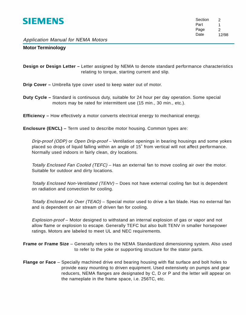
Design or Design Letter – Letter assigned by NEMA to denote standard performance characteristicsrelating to torque, starting current and slip.
Drip Cover – Umbrella type cover used to keep water out of motor.
Duty Cycle – Standard is continuous duty, suitable for 24 hour per day operation. Some specialmotors may be rated for intermittent use (15 min., 30 min., etc.).
Efficiency – How effectively a motor converts electrical energy to mechanical energy.
Enclosure (ENCL) – Term used to describe motor housing. Common types are:
Drip-proof (ODP) or Open Drip-proof – Ventilation openings in bearing housings and some yokesplaced so drops of liquid falling within an angle of 15˚ from vertical will not affect performance.Normally used indoors in fairly clean, dry locations.
Totally Enclosed Fan Cooled (TEFC) – Has an external fan to move cooling air over the motor.Suitable for outdoor and dirty locations.
Totally Enclosed Non-Ventilated (TENV) – Does not have external cooling fan but is dependenton radiation and convection for cooling.
Totally Enclosed Air Over (TEAO) – Special motor used to drive a fan blade. Has no external fanand is dependent on air stream of driven fan for cooling.
Explosion-proof – Motor designed to withstand an internal explosion of gas or vapor and notallow flame or explosion to escape. Generally TEFC but also built TENV in smaller horsepowerratings. Motors are labeled to meet UL and NEC requirements.
Frame or Frame Size – Generally refers to the NEMA Standardized dimensioning system. Also usedto refer to the yoke or supporting structure for the stator parts.
Flange or Face – Specially machined drive end bearing housing with flat surface and bolt holes toprovide easy mounting to driven equipment. Used extensively on pumps and gearreducers, NEMA flanges are designated by C, D or P and the letter will appear onthe nameplate in the frame space, i.e. 256TC, etc.
Application Manual for NEMA Motors
Motor Terminology
SectionPartPageDate
21312/98
Frequency – Hertz (HZ) Frequency in cycles per second of AC power; usually 60 Hz in U.S. and 50 Hz is common overseas.
Full-Load Amps (F.L.A.) – Current (Amps) drawn by motor operating at rated horsepower andvoltage. Important for wire and control selection and is on the motornameplate.
Hertz – See Frequency.
Horsepower – The output power rating of the motor shown on the nameplate.
Inrush Current – See Locked Rotor Amps.
Insulation – Generally refers to the maximum allowable operating temperature of the motor. Class A -105°C, B - 130°C, F - 155°C, H - 180°C. The motor rise plus the ambient temperatureshould be equal to or less than the maximum allowable temperature for the insulationclass.
KVA Code – Designated by a letter on the motor nameplate and indicates a range for values forlocked rotor kva per horsepower.
Laminations – Slotted stampings or punchings of thin (0.018”-0.026”) electrical grade steels, stackedand joined together that contain the motor windings and form the magnetic “circuit” ofa motor.
Locked Rotor Amps (L.R.A.) or Inrush Current – Line current drawn by a motor at starting or whennameplate voltage is applied and the rotor is notrotating (locked).
Locked Rotor Time or Stall Time – Time in seconds that a motor can withstand locked rotor (stalled)current without damage.
Locked Rotor Torque (L.R.T.) – Starting Torque or Breakaway Torque — The torque developed bythe motor when starting or when stalled (rotor blocked).
Maximum Run Torque – See Breakdown Torque.
NEMA – National Electrical Manufacturers Association - an organization that develops voluntarystandards of performance, dimensions, terminology, ratings and testing for motors.

Application Manual for NEMA Motors
Motor Terminology
SectionPartPageDate
21412/98
NEMA Design Code – See Design
ODP – Open Drip Proof - See Enclosure.
Power Factor – In an AC motor is the ratio of the kilowatt input to the kva input and is usuallyexpressed as a percentage.
Pull Out – See Breakdown.
Pull Up Torque – The minimum torque developed by the motor during acceleration from start tobreakdown.
Rotor – The rotating element of a motor.
Service Factor – The amount a motor can be overloaded without damage or overheating. A motorwith a 1.15 service factor can safely operate at 15% over the nameplate horsepower.
Stall Time – See Locked Rotor Time.
Starting Torque – See Locked Rotor Torque.
Stator – The stationary part of a motor that includes the stator laminations and windings.
Torque – The twisting or turning force produced by a motor and generally stated in lb.-ft.
UL – Underwriters Laboratories is an independent testing organization that sets safety standards formotors and other electrical equipment.

Application Manual for NEMA Motors
Basic Noise Theory
SectionPartPageDate
22112/98
Introduction
Noise, sound power, sound pressure, Walsh-Healey Act., decibels, free field, “A” Scale and “C” Scaleare all items appearing in motor specifications more and more frequently. The purpose of this articleis to briefly define these terms and show their interrelationship.
Walsh–Healey Act
The Federal Government saw the need for keeping noise “pollution” within reasonable limits and alsothe need for limiting noise levels to “safe” values by current medical and acoustical standards.Therefore the Walsh-Healey Act was passed and amended the 1969 setting of these limits.
The limits are based on the hours per day human beings are exposed to the noise level. Theacceptable levels range from a maximum of 155 dbA for 15 minutes to 90 dbA for 8 hours or more.
In order to understand what is required to meet this standard, it is first necessary to understand noiseand its measurement.
Noise (Sound)
Sound is a physical disturbance which results in a sensation in the ear of the listener. It is usually theresult of a mechanical vibration transferred to air and airborne to the ear of the listener.
If it is pleasing and acceptable to the ear of the listener it is called “sound.” If it is unpleasant anunwanted by the listener it is called “NOISE.” Sound emanating from a recording can be called“music” to a teenager while it is considered “noise” by his parents. Thus, individual judgment anddifference between hearing sensitivity in individuals play a large part in the difference between soundand noise.
Cause of Sound
A particle moving back and forth in a specific pattern is said to be vibrating. The sequence ofrepeated movement is called periodic motion. Each unique sequence of motions is a cycle and thetime required to move through one cycle is called the period. The FREQUENCY of the periodicmotion is the number of cycles that occur per unit of time. This is usually measured in cycles persecond or “HERTZ.” This vibrating motion causes the air particles near it to undergo vibration. Thisproduces a variation in the normal atmospheric pressure. As the disturbance spreads, if it reachesthe ear drum of a listener it will initiate vibrating motion of the ear drum and the listener experiencesthe sensation of sound.
Application Manual for NEMA Motors
Basic Noise Theory
SectionPartPageDate
22212/98
Sound travels in a wave form at a constant speed of 1127 ft/second in air. This speed is not effectedby the frequency. However, the particle velocity or the rate at which a given particle of air moves toand from when a sound wave passes is proportional to the frequency. Therefore, the frequency of thesound must be investigated when determining the effect of sound on the human ear.
Sound Pressure
When a sound wave is initiated it produces a fluctuation in the atmospheric pressure. This fluctuationin air pressure around the normal atmospheric pressure is called SOUND PRESSURE.
Normal atmospheric pressure is approximately 1 million dynes/cm2. By definition 1 dyne/cm2 is equalto 1 microbar. Therefore atmospheric pressure is approximately 1 million microbars. This is equal to14.7 pounds per square inch which is the more common term we are used to seeing.
Microphones used in noise measurement are sensitive to sound pressure, hence sound pressure hasenjoyed more popularity in the acoustical field.
Decibel and Sound Pressure Level
Sound pressure produce by different sources can vary over a wide range. Sound sources can causepressure fluctuations as low as .0002 microbars or as high as 200 microbars. This represents a rangeof 200/.0002 or a million to one. Because of this extensive range it is more convenient to uselogarithmic rather than linear scales in the acoustic field. Thus, values are expressed in SOUNDPRESSURE LEVEL (SPL) rather than sound pressure.
The unit used to express this SPL is call a DECIBEL (db). It is a dimensionless unit which expresseslogarithmically the ratio of the quantity under consideration (in this case sound rpessure) over areference value of the same dimensions as the quantity.
where P = sound pressure in microbars produced by sound sourceP0 = reference pressure in microbars taken as 0.0002 microbars
.0002 Microbars was chosen as the reference level because it is the minimum sound pressurediscernible by a sensitive human ear at 100 Hertz.
SPLBy definition 20 log (db)PP
=10 o
Application Manual for NEMA Motors
Basic Noise Theory
SectionPartPageDate
22312/98
Sound Power
As mentioned previously, microphones used in recording sound are sensitive to sound pressure. Thevalues recorded express the sound level of the area surrounding the equipment. However, they do notadequately express the energy produced by the generating source. The recorded sound levels areeffected by the direction of the sound, the distance between the sound and the microphone and theacoustical properties of the room in which the measurement is taken. They will vary from a maximumin a reverberant room to a minimum in an atmosphere where sound waves are free to travelcontinuously away from the noise source in all directions (FREE FIELD).
Because of the inability to duplicate these variables everywhere the recorded data cannot be used forscientific analysis until it has been modified to compensate for these variables.
The modified data is called SOUND POWER which is defined as the total sound energy radiated by asource per unit of time.
Again, this is expressed as SOUND POWER LEVEL (PWL) in decibels. Mathematically it is expressedas follows:
PWL = 10 log10 W (db)Wo
Where W = sound power in watts produced by sound sourceWo = reference power in watts taken as 10-12
PWL provides data which the acoustic designer can use in determining the actual overall noise levelat a given spot due to all noise generating sources.
“A” and “C” Scales
The human ear is not equally sensitive to all frequencies. Instead the human ear is more sensitive tohigher frequencies and less responsive to lower frequencies. A 1000 Hz sound will appear muchlouder to the ear than a 100 Hz sound even though they both have the same sound level. Therefore inorder to determine the effect of various frequencies it is necessary to determine the actual soundlevels of these frequencies which appear to be equally “loud” to the human ear. This has been donethrough testing a large cross section of the human race.
BY plotting these results as a family of curves and smoothing out the irregularities it has beendetermined that “weighting networks” can be designed to approximate these values. Sound picked upby the microphone and passed through these networks will be recorded by the sound meter similar tothe levels the ear thinks it hears. The two most commonly used are the “C” network and the “A”network.
Application Manual for NEMA Motors
Basic Noise Theory
SectionPartPageDate
22412/98
The “C” network (or C Scale) represents a higher “loudness level” and has a relatively flat curve. Itweights each frequency equally and therefore gives true values of sound levels eminating from thesource. Hence it is use to record sound power levels.
The “A” network (or A Scale) represents a lower “loudness level.” It discriminates primarily against thelower frequencies. Therefore it comes closest to the discrimination of the ear both for loudness of lowlevel noises and to hearing damage risk from loud noises. This “A” Scale was selected by the Walsh-Healey Act as the basis for reporting overall sound pressure levels.
Broad Band and Third Octave
The average human ear can hear over a wide range of frequencies varying from 20 Hz to 16,000 Hz.In order to simplify calculations, this range is broken into 10 parts called “OCTAVE BANDS.” Eachband covers a 2 to 1 range or the higher frequency is twice the lower. In order to further simplifymatters each band is generally referred to by its center (geometrically mean) frequency. In mostcases the lowest and the highest band contribute very little valuable data and therefore are omitted.The 8 bands normally considered are as follows: 63 Hz, 125 Hz, 250 Hz, 500 Hz, 2000 Hz, 4000 Hz,8000 Hz.
Laboratory equipment selects only the sound in the frequency band under consideration and recordsit exclusive of all other frequencies. Thus, the sound content from a source is available in 8 distinctbands for engineering analysis.
When engineering analysis requires more precise frequency data, equipment is available to furthersubdivide each octave into 3 parts. These are called “THIRD OCTAVES” which divide the full octavegeometrically rather than arithmetically.
Application Manual for NEMA Motors
Basic Noise Theory
SectionPartPageDate
22512/98
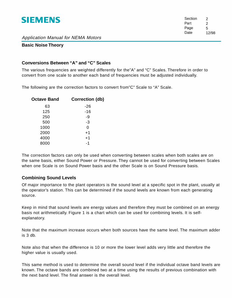
Conversions Between “A” and “C” Scales
The various frequencies are weighted differently for the”A” and “C” Scales. Therefore in order toconvert from one scale to another each band of frequencies must be adjusted individually.
The following are the correction factors to convert from”C” Scale to “A” Scale.
Octave Band Correction (db)
63 -26125 -16250 -9500 -3
1000 02000 +14000 +18000 -1
The correction factors can only be used when converting between scales when both scales are onthe same basis, either Sound Power or Pressure. They cannot be used for converting between Scaleswhen one Scale is on Sound Power basis and the other Scale is on Sound Pressure basis.
Combining Sound Levels
Of major importance to the plant operators is the sound level at a specific spot in the plant, usually atthe operator’s station. This can be determined if the sound levels are known from each generatingsource.
Keep in mind that sound levels are energy values and therefore they must be combined on an energybasis not arithmetically. Figure 1 is a chart which can be used for combining levels. It is self-explanatory.
Note that the maximum increase occurs when both sources have the same level. The maximum adderis 3 db.
Note also that when the difference is 10 or more the lower level adds very little and therefore thehigher value is usually used.
This same method is used to determine the overall sound level if the individual octave band levels areknown. The octave bands are combined two at a time using the results of previous combination withthe next band level. The final answer is the overall level.

Application Manual for NEMA Motors
Combining Sound Levels to Obtain Over-All Level
SectionPartPageDate
22612/98
0.0
0 1 2 3 4 5 6 7 8
"db" Difference Between Two Noise Levels (L1-L2)
"db
" To
Be
Ad
ded
To
Hig
her
Lev
el (
L1)
9 10 11 12 13 14 15 16
0.2
0.4
0.6
0.8
1.0
1.2
1.4
1.6
1.8
2.0
2.2
2.4
2.6
2.8
3.0
Figure 1

Application Manual for NEMA Motors
General Power Supply Variation
SectionPartPageDate
23112/98
General
Induction motors will operate successfully under the following conditions of voltage and frequencyvariation, but not necessarily in accordance with the standards established for operating under ratedconditions:
1. Where the variation in voltage does not exceed 10% above or below normal, with all phases balanced.2. Where the variation in frequency does not exceed 5% above or below normal.3. Where the sum of the voltage and frequency variations does not exceed 10% above or below
normal (provided the frequency variation does not exceed 5%)
The approximate variations in motor performance, caused by these deviations from nameplate values,are discussed on the following pages.
The effect of electrical supply variations on motor performance should be considered when selectingand applying AC Induction motors. Variation in motor supply voltage and frequency may cause:
1. An increase in motor torque and/or speed which may be damaging to the driven machine.2. A decrease in motor torque and/or speed which may cause a reduction in output of the driven machine.3. Damage to the motor.
Although the AC Induction motor is designed to successfully operate when subjected to slightvariations in power supply voltage and frequency, the performance (torque, speed, operatingtemperature, efficiency, power factor) is optimum when the power supply voltage and frequency are in accordance with the nameplate values.
Power supply variations may be classified into three categories:
1. Frequency variation from rated.2. Unbalanced voltage between phases3. Balanced phase voltage with voltage variation from rated value.

Application Manual for NEMA Motors
General Power Supply Variation
SectionPartPageDate
23212/98
For ease of understanding, we shall consider the singular effect each of the preceding categories hason motor performance. In actual practice, it is common to simultaneously encounter a combination oftwo or more of the power supply variations listed in the preceding three categories, hence thecombined effect will be the resultant of each singular effect; in other words, the effect of a particularvariation will be superimposed upon the effect of another variation.
Unbalance Voltage Between Phases
General
The multiple phase AC induction motor is designed for use on a balanced voltage system, that is, thevoltage in each phase is equal. When the voltage of each phase is unequal, a small rotating magneticfield is created. This magnetic field rotates in the opposite direction of the main magnetic field,therefore, it in effect is a “bucking” field causing induced voltages and resultant high currents. Todetermine the effect of unbalanced phase voltages on motor performance, it is necessary to expressthe voltage unbalance in percent as shown in the following formula:
Example:Actual phase voltages at motor terminal of 3 phase motor are 236,229 and 225 volts.
Determine Maximum Voltage Deviation From Average Voltage
Maximum Voltage Deviation From Average Voltage = 6 Volts
% Volts Unbalance = x 100Max. volts deviation
from avg. voltsavg. volts
Average Voltage = = 230 volts236 + 229 + 225
3
236 Volts230 Volts
6
230 Volts229 Volts
1
230 Volts225 Volts
5
% voltage unbalance = x 100 = 2.61%6
230

Application Manual for NEMA Motors
General Power Supply Variation
SectionPartPageDate
23312/98
Current
In general, a small voltage unbalance on any type of induction motor results in a considerably greatercurrent unbalance. For a given voltage deviation, the current deviation is greatest at no load anddecreases with loading with the least effect being exhibited under locked conditions. Thisphenomenon is conveniently shown in the following graph.
Full Load Speed
Unbalance phase voltage does not appreciably affect full load motor speed. There is a slight tendencyfor the full load speed to be reduced as the percentage of phase voltage unbalance increases.
Torque
Unbalanced phase voltages have little practical effect on AC induction motor torques.
Where K = 1 for locked rotor torque (LRT) and 2 for breakdown torque (BDT).
Percent Voltage Unbalance
0
20
15
10
1 2 3
5
Per
cent
Cur
rent
Unb
alan
ce
No Loa
d
Full Load
Locked
Twice Full Load
= x K x 1-
2% voltageunbalance
100
Torque withunbalancedphase voltageexpressed asa percent offull load torque
Torque withbalancedphase voltageexpressed asa percent offull load torque
Application Manual for NEMA Motors
General Power Supply Variation
SectionPartPageDate
23412/98
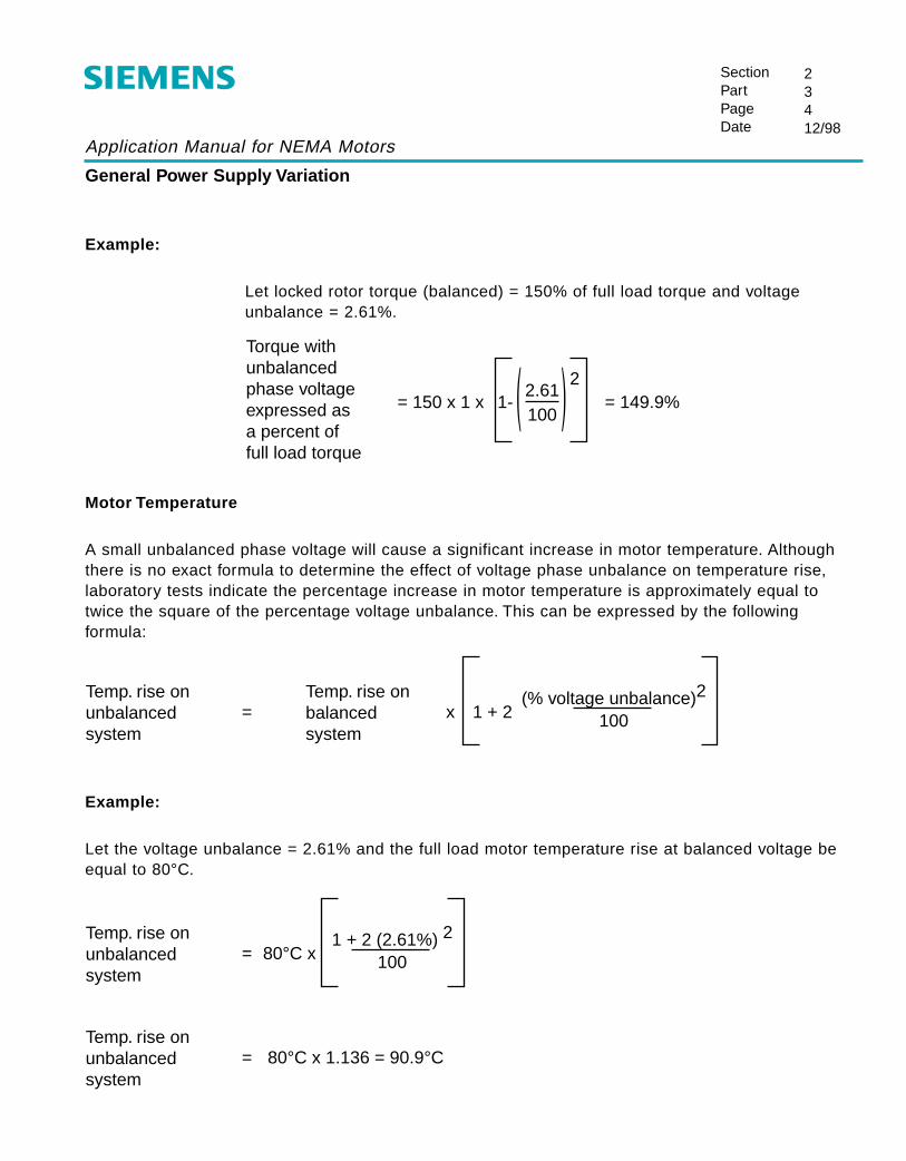
Example:
Let locked rotor torque (balanced) = 150% of full load torque and voltageunbalance = 2.61%.
Motor Temperature
A small unbalanced phase voltage will cause a significant increase in motor temperature. Althoughthere is no exact formula to determine the effect of voltage phase unbalance on temperature rise,laboratory tests indicate the percentage increase in motor temperature is approximately equal totwice the square of the percentage voltage unbalance. This can be expressed by the followingformula:
Example:
Let the voltage unbalance = 2.61% and the full load motor temperature rise at balanced voltage beequal to 80°C.
= 150 x 1 x = 149.9%1-2
2.61100
Torque withunbalancedphase voltageexpressed asa percent offull load torque
= x 1 + 2(% voltage unbalance)2
100
Temp. rise onunbalancedsystem
Temp. rise onbalancedsystem
= 80°C x1 + 2 (2.61%) 2
100
Temp. rise onunbalancedsystem
= 80°C x 1.136 = 90.9°CTemp. rise onunbalancedsystem
Application Manual for NEMA Motors
General Power Supply Variation
SectionPartPageDate
23512/98
Efficiency
A marked reduction of motor efficiency results when unbalanced phase voltages exist. The increasedcurrents caused by the reverse rotating “bucking magnetic field” cause a reduction in full loadefficiency.
Power Factor
Full load power factor decreases as the degree of voltage unbalance increases.

Application Manual for NEMA Motors
Voltage Variation From Rated Value With Balanced Phase Voltages
SectionPartPageDate
23612/98
Current
Three motor currents are often used when dealing with induction motors. They are: locked-rotor orstarting, no-load and full-load current.
Locked rotor current varies nearly directly with the applied voltage; a 10% voltage increase results inapproximately a 10% current increase.
No-load current consists primarily of magnetization current; this current establishes the magnetic fieldin the electrical steel within the motor. Increased applied voltages results in higher no-load currents;conversely, a reduction of no-load current results when the applied voltage is decreased. The degreeof no-load or magnetization current change is a function of the motor design or geometry of electricalmotor parts, type of materials used and degree of magnetic loading.
Full-load current is actually a summation of two currents; these are the no-load (magnetization)component and the load component of the full-load current.
As mentioned above, the no-load (magnetization) current increases with a voltage increase; theamount of increase is a function of the motor design.
The load component of the full-load current varies approximately inversely to the voltage variation. Avoltage increase tends to result in a corresponding decrease in the load component of the full-loadcurrent. This phenomenon can be explained by considering the fact that electrical power is basicallythe product of voltage and current. Therefore, if the mechanical load of the motor remains constant,the electrical input power to the motor also remains nearly constant; hence the load component of thecurrent is reduced when voltage is increased.
Since full-load current is the summation of both the no-load and load component currents, themanner in which the full load current varies with voltage depends on the way the two currents varywith voltage.
In general, the magnetizing (no-load) current of small motors is a large percent of the full loadcurrent. The motor magnetizing current increases when voltage is increased; hence an increase inimpressed motor voltage on small AC induction motors causes an increase in full load current.

Application Manual for NEMA Motors
Voltage Variation From Rated Value With Balanced Phase Voltages
SectionPartPageDate
23712/98
As the motor HP increases, the magnetizing current becomes a lesser percent of the total full loadcurrent; therefore, the full load current tends to decrease with increased voltage.
It should be noted that the magnetization (no-load) and load component currents are addedvectorially.
Torque
Locked, pull-up (minimum) and breakdown torque vary approximately as the square of the appliedvoltage.
Motor Temperature
Motor temperature is predominately influenced by motor current; heating due to motor current isdirectly proportional to the square of the motor current.
A 10% increase or decrease in voltage form the nameplate voltage may increase motor heating,however, such an increase in heating will not exceed safe limits provided motor is operated at valuesof nameplate HP and ambient temperature or less.
Efficiency (Full-Load)
Efficiency is a measure of the amount of electrical power lost in the form of heat compared to themechanical power delivered to the load. Higher motor currents cause higher motor temperatureswhich in turn result in a lower motor efficiency.
Power Factor (Full-Load)
Power factor is directly related to magnetization or no-load current. Higher voltages cause highermagnetization currents which in turn result in a lower power factor.
Speed (Full-Load)
Full-load speed increases slightly with a voltage increase.

Application Manual for NEMA Motors
Frequency Variation From Rated Value With Rated Balance Voltag e Applied
SectionPartPageDate
23812/98
Current
No-load, locked rotor and full-load current vary inversely with a change in applied frequency. Thechange in no-load and locked rotor current magnitude resulting from a change in frequency within±5% of rated frequency is approximately 5% or less, whereas the change in full-load current isnegligible.
Torque
Locked rotor, minimum pull up, and breakdown torques vary approximately inversely as the square of the frequency change.
Motor Temperature
Motor temperature is predominately influenced by motor current; heating due to the motor current isdirectly proportional to the square of the motor current. A 5% increase or decrease in frequency fromthe nameplate frequency may increase motor heating, however such an increase in heating will notexceed safe limits provided motor is operated at values of nameplate HP and ambient temperature orless.
Efficiency
Since a variance in frequency within ±5% of rated frequency has a negligible effect on full-load motorcurrent, the effect of frequency change on full-load motor efficiency is also negligible.
Power Factor
An increase in applied frequency causes a reduction in the magnitude of the magnetizing currentcomponent of the full-load current which causes a slight increase in power factor.
Speed (Full-Load)
Since the full-load speed is directly proportional to frequency, a 5% frequency increase will result in acorrespondent 5% increase in speed.
Siemens Energy & Automation
Solutions CommunitiesAutomotiveCementChemicalFood & BeverageMachine ToolsMarineMESMetalsMiningOil & GasPharmaceuticalProduction MachinesPulp & PaperQualityOther Industries
Product CommunitiesAutomationCNCControlsDrivesElectric MotorsInstrumentation & AnalyticsMotion ControlPower DistributionProcess AutomationResidential Electrical
Services CommunitiesIndustrial ServicesIT Plant Services
LinksNEMA web siteKnowledge@EmorySiemens Racing
Bookmark This Page
Home > Motors Community > Motor Product
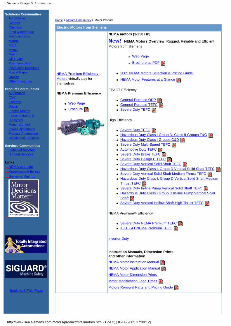
Electric Motors from Siemens
NEMA Premium Efficiency Motors virtually pay for themselves.
NEMA Premium Efficiency
● Web Page● Brochure
NEMA motors (1-250 HP)
New! NEMA Motors Overview Rugged, Reliable and Efficient Motors from Siemens
❍ Web Page
❍ Brochure as PDF
● 2005 NEMA Motors Selection & Pricing Guide
● NEMA Motor Features at a Glance
EPACT Efficiency
● General Purpose ODP ● General Purpose TEFC ● Severe Duty TEFC
High Efficiency
● Severe Duty TEFC ● Hazardous Duty Class I Group D; Class II Groups F&G ● Hazardous Duty Class I Groups C&D ● Severe Duty Multi-Speed TEFC ● Automotive Duty TEFC ● Severe Duty Brake TEFC ● Severe Duty Design C TEFC ● Severe Duty Vertical Solid Shaft TEFC ● Hazardous Duty Class I, Group D Vertical Solid Shaft TEFC ● Severe Duty Vertical Solid Shaft Medium Thrust TEFC ● Hazardous Duty CIass I, Group D Vertical Solid Shaft Medium
Thrust TEFC ● Severe Duty In-line Pump Vertical Solid Shaft TEFC ● Hazardous Duty Class I Group D In-line Pump Vertical Solid
Shaft ● Severe Duty Vertical Hollow Shaft High Thrust TEFC
NEMA Premiumtm Efficiency
● Severe Duty NEMA Premium TEFC ● IEEE 841 NEMA Premium TEFC
Inverter Duty Instruction Manuals, Dimension Prints and other informationNEMA Motor Instruction Manual
NEMA Motor Application Manual
NEMA Motor Dimension Prints
Motor Modification Lead Times
Motors Renewal Parts and Pricing Guide
http://www.sea.siemens.com/motors/product/mtallmotors.html (1 de 3) [10-06-2005 17:39:12]

Siemens Energy & Automation
Inverter Duty AC induction motors
● Inverter Duty (Variable/Constant Torque) Severe Duty TEFC
● Inverter Duty (10:1 CT) Severe Duty TEFC ● Inverter Duty (1000:1 CT) Severe Duty TEFC ● Inverter Duty (6:1 CT) Hazardous Duty Class I Group D ● Inverter Duty (6:1 CT) Hazardous Duty Class I Groups C&D
Inverter Duty Installation Operation Guide
Induction Motors Application Manual
Above NEMA motors (250 HP and above)
● Medallion Motors (766 KB)
● Large Horizontal Induction (1.4 MB)
● Performance Data for Horizontal Above NEMA (Updated Dec. 2003) (495 KB)
● Pricing Guide For Horizontal Above NEMA ( May 2005) (1.8 MB)
Dimension Prints For Above NEMA
Instruction Manuals for Above NEMA
Servo Motors
● Web Page● Brochure
Related Products from Siemens
Drives
Siemens Drives and Motors
Motor Control Centers Siemens Advanced Motor Master System (SAMMS)Motor starters & controls
Motor services
Motor Modification Centers
Motor Management Program
Motor repair at the National Service Center
Own a Siemens motor? Take our Customer Satisfaction Survey!
http://www.sea.siemens.com/motors/product/mtallmotors.html (2 de 3) [10-06-2005 17:39:12]

Siemens Energy & Automation
Technical Information and white papers
● Shaft Voltages and Bearing Currents
● Beat Noise
● Bus Transfer/Reclosing on Induction Motors
White Paper Index Page
©2005, Siemens Energy & Automation, Inc. Legal Notices / Privacy PolicyContact Us
Contact Us
About Us Training Careers
Sales Offices News Support Search
Advanced Search
Energy &Automation Home Current Stock Quote: SI
http://www.sea.siemens.com/motors/product/mtallmotors.html (3 de 3) [10-06-2005 17:39:12]
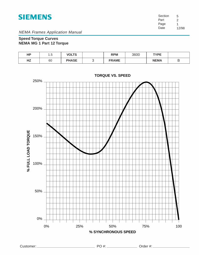
NEMA Frames Application Manual
Speed Torque CurvesNEMA MG 1 Part 12 Torque
SectionPartPageDate
52112/98
Customer:
HP 1.5 VOLTS RPM 3600 TYPE
HZ 60 PHASE 3 FRAME NEMA B
TORQUE VS. SPEED250%
200%
150%
100%
50%
0%
0% 25% 50% 75% 100
% SYNCHRONOUS SPEED
% F
UL
L L
OA
D T
OR
QU
E
PO #: Order #:

NEMA Frames Application Manual
Speed Torque CurvesNEMA MG 1 Part 12 Torque
SectionPartPageDate
52212/98
Customer:
HP 2 VOLTS RPM 3600 TYPE
HZ 60 PHASE 3 FRAME NEMA B
TORQUE VS. SPEED250%
200%
150%
100%
50%
0%
0% 25% 50% 75% 100
% SYNCHRONOUS SPEED
% F
UL
L L
OA
D T
OR
QU
E
PO #: Order #:

NEMA Frames Application Manual
Speed Torque CurvesNEMA MG 1 Part 12 Torque
SectionPartPageDate
52312/98
Customer:
HP 3 VOLTS RPM 3600 TYPE
HZ 60 PHASE 3 FRAME NEMA B
TORQUE VS. SPEED250%
200%
150%
100%
50%
0%
0% 25% 50% 75% 100
% SYNCHRONOUS SPEED
% F
UL
L L
OA
D T
OR
QU
E
PO #: Order #:

NEMA Frames Application Manual
Speed Torque CurvesNEMA MG 1 Part 12 Torque
SectionPartPageDate
52412/98
Customer:
HP 5 VOLTS RPM 3600 TYPE
HZ 60 PHASE 3 FRAME NEMA B
TORQUE VS. SPEED250%
200%
150%
100%
50%
0%
0% 25% 50% 75% 100
% SYNCHRONOUS SPEED
% F
UL
L L
OA
D T
OR
QU
E
PO #: Order #:

NEMA Frames Application Manual
Speed Torque CurvesNEMA MG 1 Part 12 Torque
SectionPartPageDate
52512/98
Customer:
HP 7.5 VOLTS RPM 3600 TYPE
HZ 60 PHASE 3 FRAME NEMA B
TORQUE VS. SPEED
0%
20%
40%
60%
80%
100%
120%
140%
160%
180%
200%
0% 25% 50% 75% 100
% SYNCHRONOUS SPEED
% F
UL
L L
OA
D T
OR
QU
E
PO #: Order #:

NEMA Frames Application Manual
Speed Torque CurvesNEMA MG 1 Part 12 Torque
SectionPartPageDate
52612/98
Customer:
HP 10 VOLTS RPM 3600 TYPE
HZ 60 PHASE 3 FRAME NEMA B
TORQUE VS. SPEED
0%
20%
40%
60%
80%
100%
120%
140%
160%
180%
200%
0% 25% 50% 75% 100
% SYNCHRONOUS SPEED
% F
UL
L L
OA
D T
OR
QU
E
PO #: Order #:

NEMA Frames Application Manual
Speed Torque CurvesNEMA MG 1 Part 12 Torque
SectionPartPageDate
52712/98
Customer:
HP 15 VOLTS RPM 3600 TYPE
HZ 60 PHASE 3 FRAME NEMA B
TORQUE VS. SPEED
0%
20%
40%
60%
80%
100%
120%
140%
160%
180%
200%
0% 25% 50% 75% 100
% SYNCHRONOUS SPEED
% F
UL
L L
OA
D T
OR
QU
E
PO #: Order #:

NEMA Frames Application Manual
Speed Torque CurvesNEMA MG 1 Part 12 Torque
SectionPartPageDate
52812/98
Customer:
HP 20 VOLTS RPM 3600 TYPE
HZ 60 PHASE 3 FRAME NEMA B
TORQUE VS. SPEED
0%
20%
40%
60%
80%
100%
120%
140%
160%
180%
200%
0% 25% 50% 75% 100
% SYNCHRONOUS SPEED
% F
UL
L L
OA
D T
OR
QU
E
PO #: Order #:

NEMA Frames Application Manual
Speed Torque CurvesNEMA MG 1 Part 12 Torque
SectionPartPageDate
52912/98
Customer:
HP 25 VOLTS RPM 3600 TYPE
HZ 60 PHASE 3 FRAME NEMA B
TORQUE VS. SPEED
0%
20%
40%
60%
80%
100%
120%
140%
160%
180%
200%
0% 25% 50% 75% 100
% SYNCHRONOUS SPEED
% F
UL
L L
OA
D T
OR
QU
E
PO #: Order #:

NEMA Frames Application Manual
Speed Torque CurvesNEMA MG 1 Part 12 Torque
SectionPartPageDate
521012/98
Customer:
HP 30 VOLTS RPM 3600 TYPE
HZ 60 PHASE 3 FRAME NEMA B
TORQUE VS. SPEED
0%
20%
40%
60%
80%
100%
120%
140%
160%
180%
200%
0% 25% 50% 75% 100
% SYNCHRONOUS SPEED
% F
UL
L L
OA
D T
OR
QU
E
PO #: Order #:

NEMA Frames Application Manual
Speed Torque CurvesNEMA MG 1 Part 12 Torque
SectionPartPageDate
521112/98
Customer:
HP 40 VOLTS RPM 3600 TYPE
HZ 60 PHASE 3 FRAME NEMA B
TORQUE VS. SPEED
0%
20%
40%
60%
80%
100%
120%
140%
160%
180%
200%
0% 25% 50% 75% 100
% SYNCHRONOUS SPEED
% F
UL
L L
OA
D T
OR
QU
E
PO #: Order #:

NEMA Frames Application Manual
Speed Torque CurvesNEMA MG 1 Part 12 Torque
SectionPartPageDate
521212/98
Customer:
HP 50 VOLTS RPM 3600 TYPE
HZ 60 PHASE 3 FRAME NEMA B
TORQUE VS. SPEED
0%
20%
40%
60%
80%
100%
120%
140%
160%
180%
200%
0% 25% 50% 75% 100
% SYNCHRONOUS SPEED
% F
UL
L L
OA
D T
OR
QU
E
PO #: Order #:

NEMA Frames Application Manual
Speed Torque CurvesNEMA MG 1 Part 12 Torque
SectionPartPageDate
521312/98
Customer:
HP 60 VOLTS RPM 3600 TYPE
HZ 60 PHASE 3 FRAME NEMA B
TORQUE VS. SPEED
0%
20%
40%
60%
80%
100%
120%
140%
160%
180%
200%
0% 25% 50% 75% 100
% SYNCHRONOUS SPEED
% F
UL
L L
OA
D T
OR
QU
E
PO #: Order #:

NEMA Frames Application Manual
Speed Torque CurvesNEMA MG 1 Part 12 Torque
SectionPartPageDate
521412/98
Customer:
HP 75 VOLTS RPM 3600 TYPE
HZ 60 PHASE 3 FRAME NEMA B
TORQUE VS. SPEED
0%
20%
40%
60%
80%
100%
120%
140%
160%
180%
200%
0% 25% 50% 75% 100
% SYNCHRONOUS SPEED
% F
UL
L L
OA
D T
OR
QU
E
PO #: Order #:

NEMA Frames Application Manual
Speed Torque CurvesNEMA MG 1 Part 12 Torque
SectionPartPageDate
521512/98
Customer:
HP 100 VOLTS RPM 3600 TYPE
HZ 60 PHASE 3 FRAME NEMA B
TORQUE VS. SPEED
0%
20%
40%
60%
80%
100%
120%
140%
160%
180%
200%
0% 25% 50% 75% 100
% SYNCHRONOUS SPEED
% F
UL
L L
OA
D T
OR
QU
E
PO #: Order #:

NEMA Frames Application Manual
Speed Torque CurvesNEMA MG 1 Part 12 Torque
SectionPartPageDate
521612/98
Customer:
HP 125 VOLTS RPM 3600 TYPE
HZ 60 PHASE 3 FRAME NEMA B
TORQUE VS. SPEED
0%
20%
40%
60%
80%
100%
120%
140%
160%
180%
200%
0% 25% 50% 75% 100
% SYNCHRONOUS SPEED
% F
UL
L L
OA
D T
OR
QU
E
PO #: Order #:

NEMA Frames Application Manual
Speed Torque CurvesNEMA MG 1 Part 12 Torque
SectionPartPageDate
521712/98
Customer:
HP 150 VOLTS RPM 3600 TYPE
HZ 60 PHASE 3 FRAME NEMA B
TORQUE VS. SPEED
0%
20%
40%
60%
80%
100%
120%
140%
160%
180%
200%
0% 25% 50% 75% 100
% SYNCHRONOUS SPEED
% F
UL
L L
OA
D T
OR
QU
E
PO #: Order #:
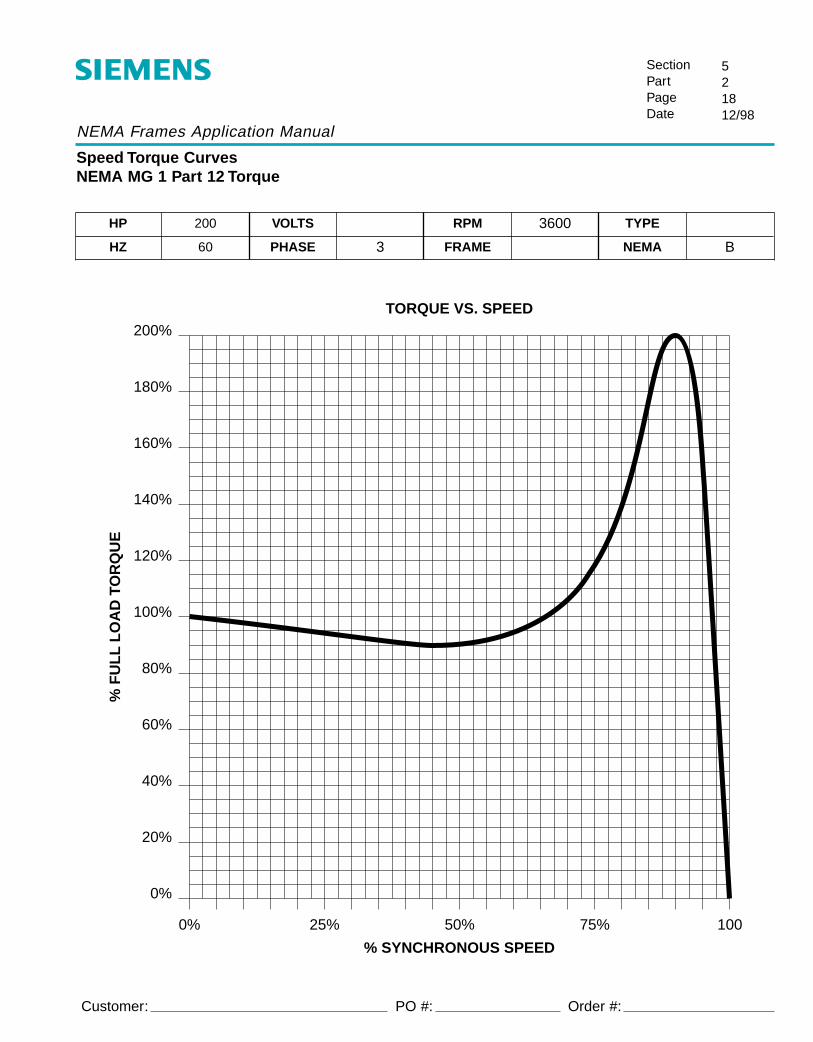
NEMA Frames Application Manual
Speed Torque CurvesNEMA MG 1 Part 12 Torque
SectionPartPageDate
521812/98
Customer:
HP 200 VOLTS RPM 3600 TYPE
HZ 60 PHASE 3 FRAME NEMA B
TORQUE VS. SPEED
0%
20%
40%
60%
80%
100%
120%
140%
160%
180%
200%
0% 25% 50% 75% 100
% SYNCHRONOUS SPEED
% F
UL
L L
OA
D T
OR
QU
E
PO #: Order #:

NEMA Frames Application Manual
Speed Torque CurvesNEMA MG 1 Part 12 Torque
SectionPartPageDate
521912/98
Customer:
HP 250 VOLTS RPM 3600 TYPE
HZ 60 PHASE 3 FRAME NEMA B
TORQUE VS. SPEED
0%
20%
40%
60%
80%
100%
120%
140%
160%
180%
0% 25% 50% 75% 100
% SYNCHRONOUS SPEED
% F
UL
L L
OA
D T
OR
QU
E
PO #: Order #:
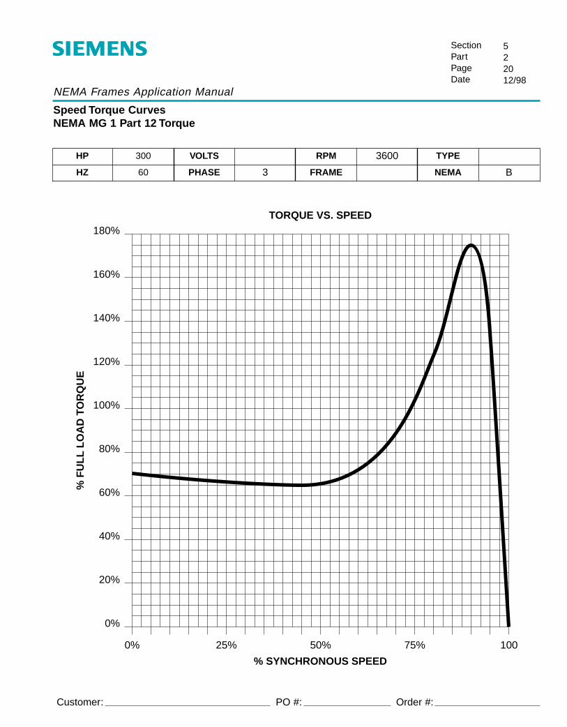
NEMA Frames Application Manual
Speed Torque CurvesNEMA MG 1 Part 12 Torque
SectionPartPageDate
522012/98
Customer:
HP 300 VOLTS RPM 3600 TYPE
HZ 60 PHASE 3 FRAME NEMA B
TORQUE VS. SPEED
0%
20%
40%
60%
80%
100%
120%
140%
160%
180%
0% 25% 50% 75% 100
% SYNCHRONOUS SPEED
% F
UL
L L
OA
D T
OR
QU
E
PO #: Order #:

NEMA Frames Application Manual
Speed Torque CurvesNEMA MG 1 Part 12 Torque
SectionPartPageDate
522112/98
Customer:
HP 350 VOLTS RPM 3600 TYPE
HZ 60 PHASE 3 FRAME NEMA B
TORQUE VS. SPEED
0%
20%
40%
60%
80%
100%
120%
140%
160%
180%
0% 25% 50% 75% 100
% SYNCHRONOUS SPEED
% F
UL
L L
OA
D T
OR
QU
E
PO #: Order #:

NEMA Frames Application Manual
Speed Torque CurvesNEMA MG 1 Part 12 Torque
SectionPartPageDate
522212/98
Customer:
HP 400 VOLTS RPM 3600 TYPE
HZ 60 PHASE 3 FRAME NEMA B
TORQUE VS. SPEED
0%
20%
40%
60%
80%
100%
120%
140%
160%
180%
0% 25% 50% 75% 100
% SYNCHRONOUS SPEED
% F
UL
L L
OA
D T
OR
QU
E
PO #: Order #:

NEMA Frames Application Manual
Speed Torque CurvesNEMA MG 1 Part 12 Torque
SectionPartPageDate
522312/98
Customer:
HP 450 VOLTS RPM 3600 TYPE
HZ 60 PHASE 3 FRAME NEMA B
TORQUE VS. SPEED
0%
20%
40%
60%
80%
100%
120%
140%
160%
180%
0% 25% 50% 75% 100
% SYNCHRONOUS SPEED
% F
UL
L L
OA
D T
OR
QU
E
PO #: Order #:

NEMA Frames Application Manual
Speed Torque CurvesNEMA MG 1 Part 12 Torque
SectionPartPageDate
522412/98
Customer:
HP 1 VOLTS RPM 1800 TYPE
HZ 60 PHASE 3 FRAME NEMA B
TORQUE VS. SPEED
0%
50%
100%
150%
200%
250%
300%
0% 25% 50% 75% 100
% SYNCHRONOUS SPEED
% F
UL
L L
OA
D T
OR
QU
E
PO #: Order #:

NEMA Frames Application Manual
Speed Torque CurvesNEMA MG 1 Part 12 Torque
SectionPartPageDate
522512/98
Customer:
HP 1.5 VOLTS RPM 1800 TYPE
HZ 60 PHASE 3 FRAME NEMA B
TORQUE VS. SPEED
0%
50%
100%
150%
200%
250%
300%
0% 25% 50% 75% 100
% SYNCHRONOUS SPEED
% F
UL
L L
OA
D T
OR
QU
E
PO #: Order #:
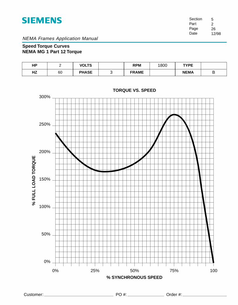
NEMA Frames Application Manual
Speed Torque CurvesNEMA MG 1 Part 12 Torque
SectionPartPageDate
522612/98
Customer:
HP 2 VOLTS RPM 1800 TYPE
HZ 60 PHASE 3 FRAME NEMA B
TORQUE VS. SPEED
0%
50%
100%
150%
200%
250%
300%
0% 25% 50% 75% 100
% SYNCHRONOUS SPEED
% F
UL
L L
OA
D T
OR
QU
E
PO #: Order #:
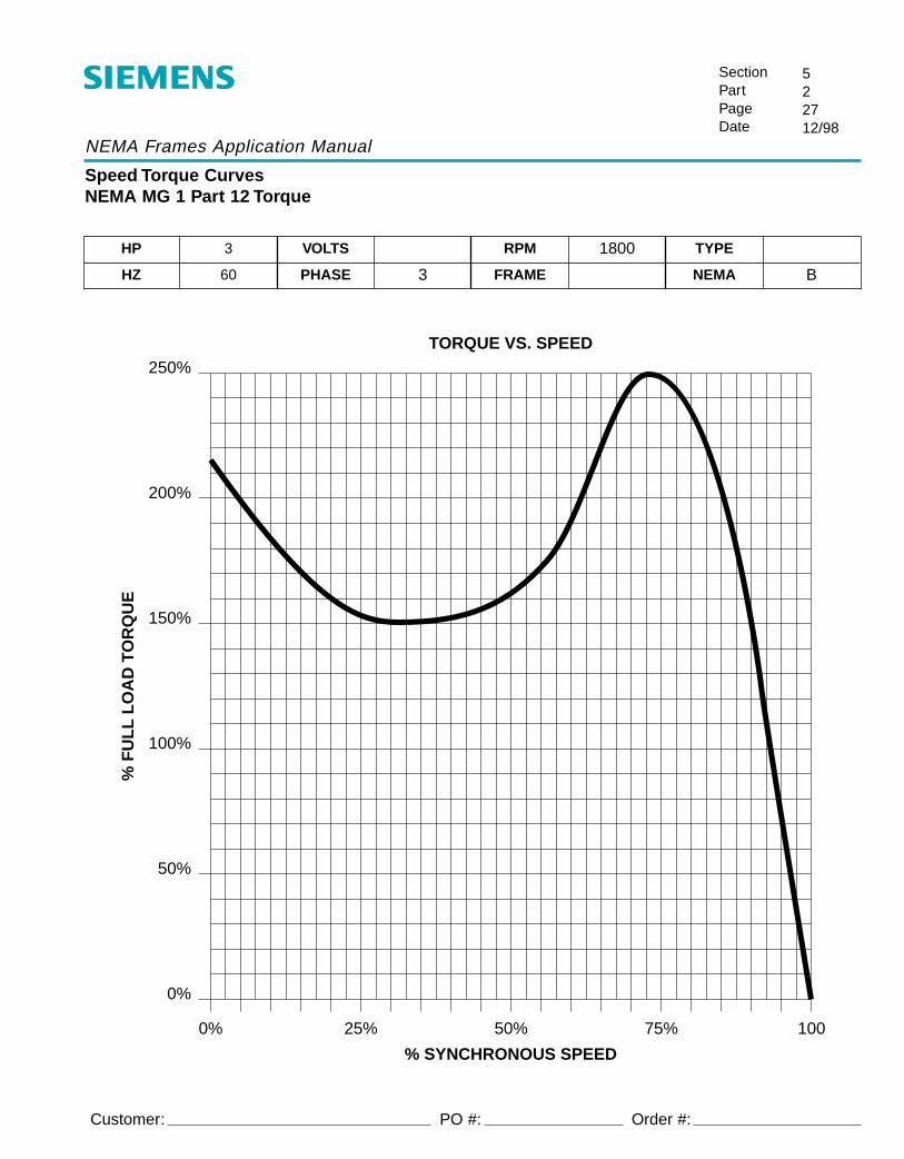
NEMA Frames Application Manual
Speed Torque CurvesNEMA MG 1 Part 12 Torque
SectionPartPageDate
522712/98
Customer:
HP 3 VOLTS RPM 1800 TYPE
HZ 60 PHASE 3 FRAME NEMA B
TORQUE VS. SPEED250%
200%
150%
100%
50%
0%
0% 25% 50% 75% 100
% SYNCHRONOUS SPEED
% F
UL
L L
OA
D T
OR
QU
E
PO #: Order #:

NEMA Frames Application Manual
Speed Torque CurvesNEMA MG 1 Part 12 Torque
SectionPartPageDate
522812/98
Customer:
HP 5 VOLTS RPM 1800 TYPE
HZ 60 PHASE 3 FRAME NEMA B
TORQUE VS. SPEED250%
200%
150%
100%
50%
0%
0% 25% 50% 75% 100
% SYNCHRONOUS SPEED
% F
UL
L L
OA
D T
OR
QU
E
PO #: Order #:
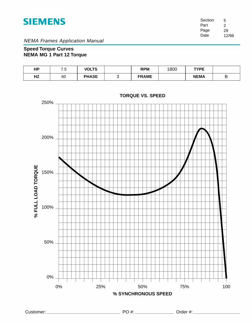
NEMA Frames Application Manual
Speed Torque CurvesNEMA MG 1 Part 12 Torque
SectionPartPageDate
522912/98
Customer:
HP 7.5 VOLTS RPM 1800 TYPE
HZ 60 PHASE 3 FRAME NEMA B
TORQUE VS. SPEED250%
200%
150%
100%
50%
0%
0% 25% 50% 75% 100
% SYNCHRONOUS SPEED
% F
UL
L L
OA
D T
OR
QU
E
PO #: Order #:
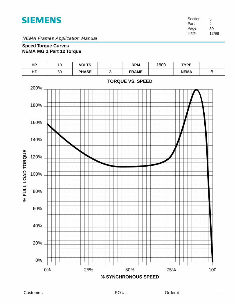
NEMA Frames Application Manual
Speed Torque CurvesNEMA MG 1 Part 12 Torque
SectionPartPageDate
523012/98
Customer:
HP 10 VOLTS RPM 1800 TYPE
HZ 60 PHASE 3 FRAME NEMA B
TORQUE VS. SPEED
0%
20%
40%
60%
80%
100%
120%
140%
160%
180%
200%
0% 25% 50% 75% 100
% SYNCHRONOUS SPEED
% F
UL
L L
OA
D T
OR
QU
E
PO #: Order #:

NEMA Frames Application Manual
Speed Torque CurvesNEMA MG 1 Part 12 Torque
SectionPartPageDate
523112/98
Customer:
HP 15 VOLTS RPM 1800 TYPE
HZ 60 PHASE 3 FRAME NEMA B
TORQUE VS. SPEED
0%
20%
40%
60%
80%
100%
120%
140%
160%
180%
200%
0% 25% 50% 75% 100
% SYNCHRONOUS SPEED
% F
UL
L L
OA
D T
OR
QU
E
PO #: Order #:

NEMA Frames Application Manual
Speed Torque CurvesNEMA MG 1 Part 12 Torque
SectionPartPageDate
523212/98
Customer:
HP 20 VOLTS RPM 1800 TYPE
HZ 60 PHASE 3 FRAME NEMA B
TORQUE VS. SPEED
0%
20%
40%
60%
80%
100%
120%
140%
160%
180%
200%
0% 25% 50% 75% 100
% SYNCHRONOUS SPEED
% F
UL
L L
OA
D T
OR
QU
E
PO #: Order #:
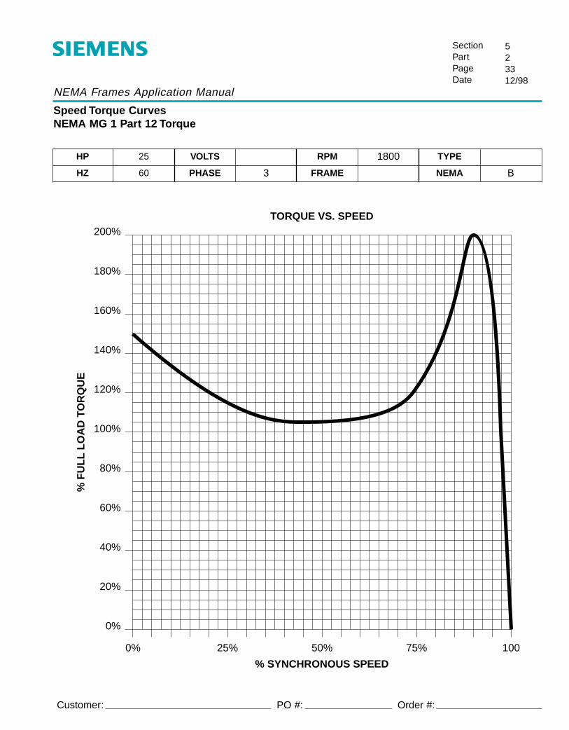
NEMA Frames Application Manual
Speed Torque CurvesNEMA MG 1 Part 12 Torque
SectionPartPageDate
523312/98
Customer:
HP 25 VOLTS RPM 1800 TYPE
HZ 60 PHASE 3 FRAME NEMA B
TORQUE VS. SPEED
0%
20%
40%
60%
80%
100%
120%
140%
160%
180%
200%
0% 25% 50% 75% 100
% SYNCHRONOUS SPEED
% F
UL
L L
OA
D T
OR
QU
E
PO #: Order #:

NEMA Frames Application Manual
Speed Torque CurvesNEMA MG 1 Part 12 Torque
SectionPartPageDate
523412/98
Customer:
HP 30 VOLTS RPM 1800 TYPE
HZ 60 PHASE 3 FRAME NEMA B
TORQUE VS. SPEED
0%
20%
40%
60%
80%
100%
120%
140%
160%
180%
200%
0% 25% 50% 75% 100
% SYNCHRONOUS SPEED
% F
UL
L L
OA
D T
OR
QU
E
PO #: Order #:

NEMA Frames Application Manual
Speed Torque CurvesNEMA MG 1 Part 12 Torque
SectionPartPageDate
523512/98
Customer:
HP 40 VOLTS RPM 1800 TYPE
HZ 60 PHASE 3 FRAME NEMA B
TORQUE VS. SPEED
0%
20%
40%
60%
80%
100%
120%
140%
160%
180%
200%
0% 25% 50% 75% 100
% SYNCHRONOUS SPEED
% F
UL
L L
OA
D T
OR
QU
E
PO #: Order #:

NEMA Frames Application Manual
Speed Torque CurvesNEMA MG 1 Part 12 Torque
SectionPartPageDate
523612/98
Customer:
HP 50 VOLTS RPM 1800 TYPE
HZ 60 PHASE 3 FRAME NEMA B
TORQUE VS. SPEED
0%
20%
40%
60%
80%
100%
120%
140%
160%
180%
200%
0% 25% 50% 75% 100
% SYNCHRONOUS SPEED
% F
UL
L L
OA
D T
OR
QU
E
PO #: Order #:

NEMA Frames Application Manual
Speed Torque CurvesNEMA MG 1 Part 12 Torque
SectionPartPageDate
523712/98
Customer:
HP 60 VOLTS RPM 1800 TYPE
HZ 60 PHASE 3 FRAME NEMA B
TORQUE VS. SPEED
0%
20%
40%
60%
80%
100%
120%
140%
160%
180%
200%
0% 25% 50% 75% 100
% SYNCHRONOUS SPEED
% F
UL
L L
OA
D T
OR
QU
E
PO #: Order #:

NEMA Frames Application Manual
Speed Torque CurvesNEMA MG 1 Part 12 Torque
SectionPartPageDate
523812/98
Customer:
HP 75 VOLTS RPM 1800 TYPE
HZ 60 PHASE 3 FRAME NEMA B
TORQUE VS. SPEED
0%
20%
40%
60%
80%
100%
120%
140%
160%
180%
200%
0% 25% 50% 75% 100
% SYNCHRONOUS SPEED
% F
UL
L L
OA
D T
OR
QU
E
PO #: Order #:

NEMA Frames Application Manual
Speed Torque CurvesNEMA MG 1 Part 12 Torque
SectionPartPageDate
523912/98
Customer:
HP 100 VOLTS RPM 1800 TYPE
HZ 60 PHASE 3 FRAME NEMA B
TORQUE VS. SPEED
0%
20%
40%
60%
80%
100%
120%
140%
160%
180%
200%
0% 25% 50% 75% 100
% SYNCHRONOUS SPEED
% F
UL
L L
OA
D T
OR
QU
E
PO #: Order #:

NEMA Frames Application Manual
Speed Torque CurvesNEMA MG 1 Part 12 Torque
SectionPartPageDate
524012/98
Customer:
HP 125 VOLTS RPM 1800 TYPE
HZ 60 PHASE 3 FRAME NEMA B
TORQUE VS. SPEED
0%
20%
40%
60%
80%
100%
120%
140%
160%
180%
200%
0% 25% 50% 75% 100
% SYNCHRONOUS SPEED
% F
UL
L L
OA
D T
OR
QU
E
PO #: Order #:

NEMA Frames Application Manual
Speed Torque CurvesNEMA MG 1 Part 12 Torque
SectionPartPageDate
524112/98
Customer:
HP 150 VOLTS RPM 1800 TYPE
HZ 60 PHASE 3 FRAME NEMA B
TORQUE VS. SPEED
0%
20%
40%
60%
80%
100%
120%
140%
160%
180%
200%
0% 25% 50% 75% 100
% SYNCHRONOUS SPEED
% F
UL
L L
OA
D T
OR
QU
E
PO #: Order #:

NEMA Frames Application Manual
Speed Torque CurvesNEMA MG 1 Part 12 Torque
SectionPartPageDate
524212/98
Customer:
HP 200 VOLTS RPM 1800 TYPE
HZ 60 PHASE 3 FRAME NEMA B
TORQUE VS. SPEED
0%
20%
40%
60%
80%
100%
120%
140%
160%
180%
200%
0% 25% 50% 75% 100
% SYNCHRONOUS SPEED
% F
UL
L L
OA
D T
OR
QU
E
PO #: Order #:

NEMA Frames Application Manual
Speed Torque CurvesNEMA MG 1 Part 12 Torque
SectionPartPageDate
524312/98
Customer:
HP 250 VOLTS RPM 1800 TYPE
HZ 60 PHASE 3 FRAME NEMA B
TORQUE VS. SPEED
0%
20%
40%
60%
80%
100%
120%
140%
160%
180%
0% 25% 50% 75% 100
% SYNCHRONOUS SPEED
% F
UL
L L
OA
D T
OR
QU
E
PO #: Order #:

NEMA Frames Application Manual
Speed Torque CurvesNEMA MG 1 Part 12 Torque
SectionPartPageDate
524412/98
Customer:
HP 300 VOLTS RPM 1800 TYPE
HZ 60 PHASE 3 FRAME NEMA B
TORQUE VS. SPEED
0%
20%
40%
60%
80%
100%
120%
140%
160%
180%
0% 25% 50% 75% 100
% SYNCHRONOUS SPEED
% F
UL
L L
OA
D T
OR
QU
E
PO #: Order #:

NEMA Frames Application Manual
Speed Torque CurvesNEMA MG 1 Part 12 Torque
SectionPartPageDate
524512/98
Customer:
HP 350 VOLTS RPM 1800 TYPE
HZ 60 PHASE 3 FRAME NEMA B
TORQUE VS. SPEED
0%
20%
40%
60%
80%
100%
120%
140%
160%
180%
0% 25% 50% 75% 100
% SYNCHRONOUS SPEED
% F
UL
L L
OA
D T
OR
QU
E
PO #: Order #:

NEMA Frames Application Manual
Speed Torque CurvesNEMA MG 1 Part 12 Torque
SectionPartPageDate
524612/98
Customer:
HP 400 VOLTS RPM 1800 TYPE
HZ 60 PHASE 3 FRAME NEMA B
TORQUE VS. SPEED
0%
20%
40%
60%
80%
100%
120%
140%
160%
180%
0% 25% 50% 75% 100
% SYNCHRONOUS SPEED
% F
UL
L L
OA
D T
OR
QU
E
PO #: Order #:
NEMA Frames Application Manual
Speed Torque CurvesNEMA MG 1 Part 12 Torque
SectionPartPageDate
524712/98
Customer:
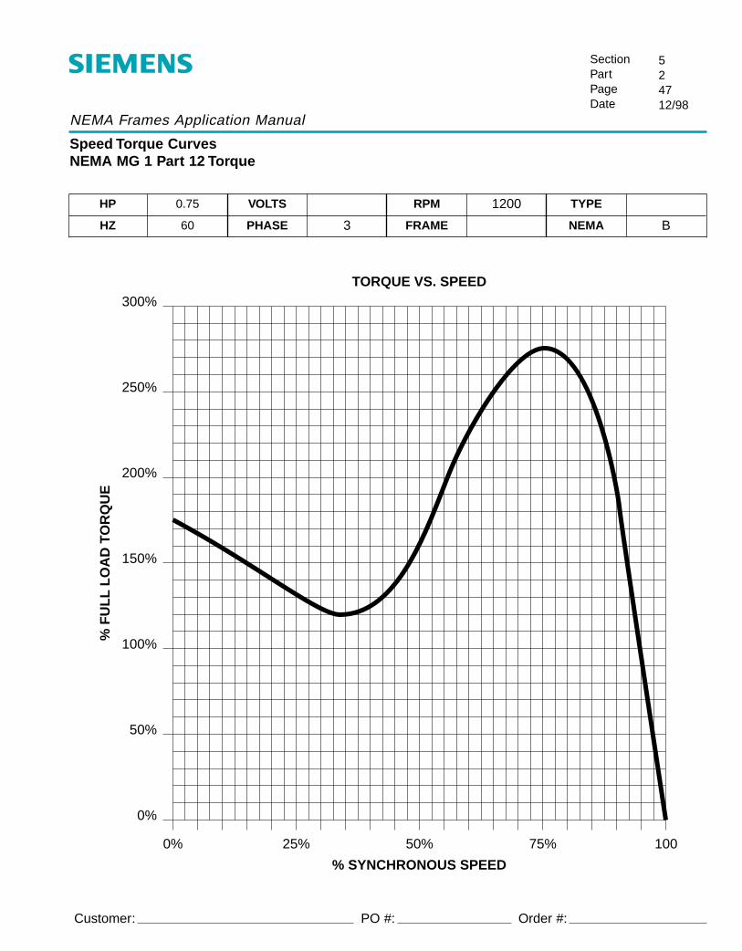
HP 0.75 VOLTS RPM 1200 TYPE
HZ 60 PHASE 3 FRAME NEMA B
TORQUE VS. SPEED
0%
50%
100%
150%
200%
250%
300%
0% 25% 50% 75% 100
% SYNCHRONOUS SPEED
% F
UL
L L
OA
D T
OR
QU
E
PO #: Order #:

NEMA Frames Application Manual
Speed Torque CurvesNEMA MG 1 Part 12 Torque
SectionPartPageDate
524812/98
Customer:
HP 1 VOLTS RPM 1200 TYPE
HZ 60 PHASE 3 FRAME NEMA B
TORQUE VS. SPEED
0%
50%
100%
150%
200%
250%
300%
0% 25% 50% 75% 100
% SYNCHRONOUS SPEED
% F
UL
L L
OA
D T
OR
QU
E
PO #: Order #:
NEMA Frames Application Manual
Speed Torque CurvesNEMA MG 1 Part 12 Torque
SectionPartPageDate
524912/98
Customer:
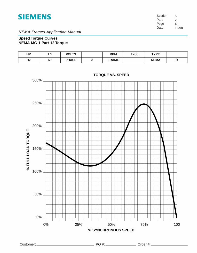
HP 1.5 VOLTS RPM 1200 TYPE
HZ 60 PHASE 3 FRAME NEMA B
TORQUE VS. SPEED
0%
50%
100%
150%
200%
250%
300%
0% 25% 50% 75% 100
% SYNCHRONOUS SPEED
% F
UL
L L
OA
D T
OR
QU
E
PO #: Order #:
NEMA Frames Application Manual
Speed Torque CurvesNEMA MG 1 Part 12 Torque
SectionPartPageDate
525012/98
Customer:
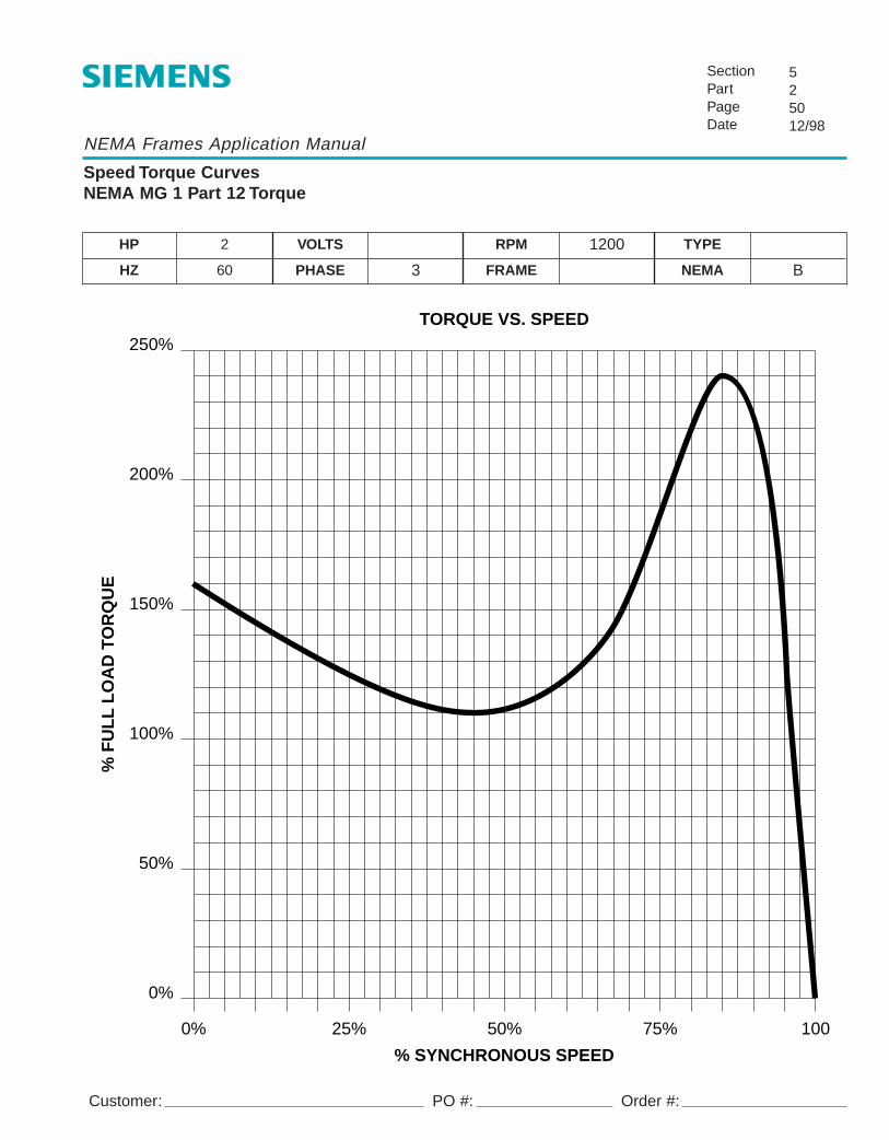
HP 2 VOLTS RPM 1200 TYPE
HZ 60 PHASE 3 FRAME NEMA B
TORQUE VS. SPEED250%
200%
150%
100%
50%
0%
0% 25% 50% 75% 100
% SYNCHRONOUS SPEED
% F
UL
L L
OA
D T
OR
QU
E
PO #: Order #:

NEMA Frames Application Manual
Speed Torque CurvesNEMA MG 1 Part 12 Torque
SectionPartPageDate
525112/98
Customer:
HP 3 VOLTS RPM 1200 TYPE
HZ 60 PHASE 3 FRAME NEMA B
TORQUE VS. SPEED250%
200%
150%
100%
50%
0%
0% 25% 50% 75% 100
% SYNCHRONOUS SPEED
% F
UL
L L
OA
D T
OR
QU
E
PO #: Order #:

NEMA Frames Application Manual
Speed Torque CurvesNEMA MG 1 Part 12 Torque
SectionPartPageDate
525212/98
Customer:
HP 5 VOLTS RPM 1200 TYPE
HZ 60 PHASE 3 FRAME NEMA B
TORQUE VS. SPEED250%
200%
150%
100%
50%
0%
0% 25% 50% 75% 100
% SYNCHRONOUS SPEED
% F
UL
L L
OA
D T
OR
QU
E
PO #: Order #:
NEMA Frames Application Manual
Speed Torque CurvesNEMA MG 1 Part 12 Torque
SectionPartPageDate
525312/98
Customer:
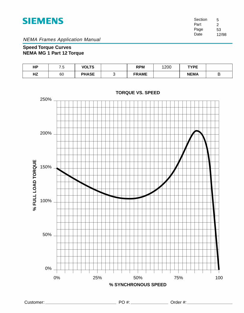
HP 7.5 VOLTS RPM 1200 TYPE
HZ 60 PHASE 3 FRAME NEMA B
TORQUE VS. SPEED250%
200%
150%
100%
50%
0%
0% 25% 50% 75% 100
% SYNCHRONOUS SPEED
% F
UL
L L
OA
D T
OR
QU
E
PO #: Order #:

NEMA Frames Application Manual
Speed Torque CurvesNEMA MG 1 Part 12 Torque
SectionPartPageDate
525412/98
Customer:
HP 10 VOLTS RPM 1200 TYPE
HZ 60 PHASE 3 FRAME NEMA B
TORQUE VS. SPEED
0%
20%
40%
60%
80%
100%
120%
140%
160%
180%
200%
0% 25% 50% 75% 100
% SYNCHRONOUS SPEED
% F
UL
L L
OA
D T
OR
QU
E
PO #: Order #:

NEMA Frames Application Manual
Speed Torque CurvesNEMA MG 1 Part 12 Torque
SectionPartPageDate
525512/98
Customer:
HP 15 VOLTS RPM 1200 TYPE
HZ 60 PHASE 3 FRAME NEMA B
TORQUE VS. SPEED
0%
20%
40%
60%
80%
100%
120%
140%
160%
180%
200%
0% 25% 50% 75% 100
% SYNCHRONOUS SPEED
% F
UL
L L
OA
D T
OR
QU
E
PO #: Order #:

NEMA Frames Application Manual
Speed Torque CurvesNEMA MG 1 Part 12 Torque
SectionPartPageDate
525612/98
Customer:
HP 20 VOLTS RPM 1200 TYPE
HZ 60 PHASE 3 FRAME NEMA B
TORQUE VS. SPEED
0%
20%
40%
60%
80%
100%
120%
140%
160%
180%
200%
0% 25% 50% 75% 100
% SYNCHRONOUS SPEED
% F
UL
L L
OA
D T
OR
QU
E
PO #: Order #:

NEMA Frames Application Manual
Speed Torque CurvesNEMA MG 1 Part 12 Torque
SectionPartPageDate
525712/98
Customer:
HP 25 VOLTS RPM 1200 TYPE
HZ 60 PHASE 3 FRAME NEMA B
TORQUE VS. SPEED
0%
20%
40%
60%
80%
100%
120%
140%
160%
180%
200%
0% 25% 50% 75% 100
% SYNCHRONOUS SPEED
% F
UL
L L
OA
D T
OR
QU
E
PO #: Order #:

NEMA Frames Application Manual
Speed Torque CurvesNEMA MG 1 Part 12 Torque
SectionPartPageDate
525812/98
Customer:
HP 30 VOLTS RPM 1200 TYPE
HZ 60 PHASE 3 FRAME NEMA B
TORQUE VS. SPEED
0%
20%
40%
60%
80%
100%
120%
140%
160%
180%
200%
0% 25% 50% 75% 100
% SYNCHRONOUS SPEED
% F
UL
L L
OA
D T
OR
QU
E
PO #: Order #:
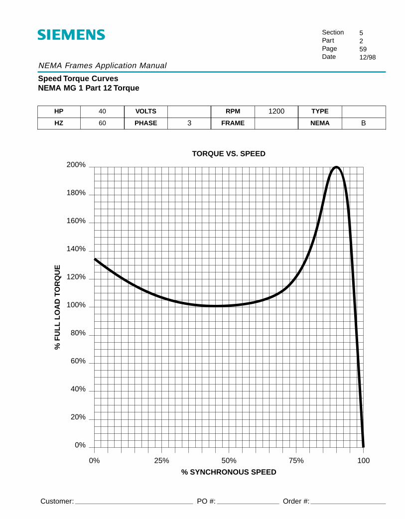
NEMA Frames Application Manual
Speed Torque CurvesNEMA MG 1 Part 12 Torque
SectionPartPageDate
525912/98
Customer:
HP 40 VOLTS RPM 1200 TYPE
HZ 60 PHASE 3 FRAME NEMA B
TORQUE VS. SPEED
0%
20%
40%
60%
80%
100%
120%
140%
160%
180%
200%
0% 25% 50% 75% 100
% SYNCHRONOUS SPEED
% F
UL
L L
OA
D T
OR
QU
E
PO #: Order #:

NEMA Frames Application Manual
Speed Torque CurvesNEMA MG 1 Part 12 Torque
SectionPartPageDate
526012/98
Customer:
HP 50 VOLTS RPM 1200 TYPE
HZ 60 PHASE 3 FRAME NEMA B
TORQUE VS. SPEED
0%
20%
40%
60%
80%
100%
120%
140%
160%
180%
200%
0% 25% 50% 75% 100
% SYNCHRONOUS SPEED
% F
UL
L L
OA
D T
OR
QU
E
PO #: Order #:

NEMA Frames Application Manual
Speed Torque CurvesNEMA MG 1 Part 12 Torque
SectionPartPageDate
526112/98
Customer:
HP 60 VOLTS RPM 1200 TYPE
HZ 60 PHASE 3 FRAME NEMA B
TORQUE VS. SPEED
0%
20%
40%
60%
80%
100%
120%
140%
160%
180%
200%
0% 25% 50% 75% 100
% SYNCHRONOUS SPEED
% F
UL
L L
OA
D T
OR
QU
E
PO #: Order #:

NEMA Frames Application Manual
Speed Torque CurvesNEMA MG 1 Part 12 Torque
SectionPartPageDate
526212/98
Customer:
HP 75 VOLTS RPM 1200 TYPE
HZ 60 PHASE 3 FRAME NEMA B
TORQUE VS. SPEED
0%
20%
40%
60%
80%
100%
120%
140%
160%
180%
200%
0% 25% 50% 75% 100
% SYNCHRONOUS SPEED
% F
UL
L L
OA
D T
OR
QU
E
PO #: Order #:

NEMA Frames Application Manual
Speed Torque CurvesNEMA MG 1 Part 12 Torque
SectionPartPageDate
526312/98
Customer:
HP 100 VOLTS RPM 1200 TYPE
HZ 60 PHASE 3 FRAME NEMA B
TORQUE VS. SPEED
0%
20%
40%
60%
80%
100%
120%
140%
160%
180%
200%
0% 25% 50% 75% 100
% SYNCHRONOUS SPEED
% F
UL
L L
OA
D T
OR
QU
E
PO #: Order #:

NEMA Frames Application Manual
Speed Torque CurvesNEMA MG 1 Part 12 Torque
SectionPartPageDate
526412/98
Customer:
HP 125 VOLTS RPM 1200 TYPE
HZ 60 PHASE 3 FRAME NEMA B
TORQUE VS. SPEED
0%
20%
40%
60%
80%
100%
120%
140%
160%
180%
200%
0% 25% 50% 75% 100
% SYNCHRONOUS SPEED
% F
UL
L L
OA
D T
OR
QU
E
PO #: Order #:

NEMA Frames Application Manual
Speed Torque CurvesNEMA MG 1 Part 12 Torque
SectionPartPageDate
526512/98
Customer:
HP 150 VOLTS RPM 1200 TYPE
HZ 60 PHASE 3 FRAME NEMA B
TORQUE VS. SPEED
0%
20%
40%
60%
80%
100%
120%
140%
160%
180%
200%
0% 25% 50% 75% 100
% SYNCHRONOUS SPEED
% F
UL
L L
OA
D T
OR
QU
E
PO #: Order #:

NEMA Frames Application Manual
Speed Torque CurvesNEMA MG 1 Part 12 Torque
SectionPartPageDate
526612/98
Customer:
HP 200 VOLTS RPM 1200 TYPE
HZ 60 PHASE 3 FRAME NEMA B
TORQUE VS. SPEED
0%
20%
40%
60%
80%
100%
120%
140%
160%
180%
200%
0% 25% 50% 75% 100
% SYNCHRONOUS SPEED
% F
UL
L L
OA
D T
OR
QU
E
PO #: Order #:

NEMA Frames Application Manual
Speed Torque CurvesNEMA MG 1 Part 12 Torque
SectionPartPageDate
526712/98
Customer:
HP 250 VOLTS RPM 1200 TYPE
HZ 60 PHASE 3 FRAME NEMA B
TORQUE VS. SPEED
0%
20%
40%
60%
80%
100%
120%
140%
160%
180%
200%
0% 25% 50% 75% 100
% SYNCHRONOUS SPEED
% F
UL
L L
OA
D T
OR
QU
E
PO #: Order #:
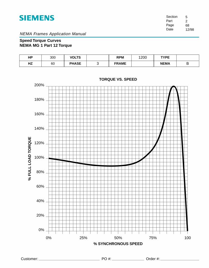
NEMA Frames Application Manual
Speed Torque CurvesNEMA MG 1 Part 12 Torque
SectionPartPageDate
526812/98
Customer:
HP 300 VOLTS RPM 1200 TYPE
HZ 60 PHASE 3 FRAME NEMA B
TORQUE VS. SPEED
0%
20%
40%
60%
80%
100%
120%
140%
160%
180%
200%
0% 25% 50% 75% 100
% SYNCHRONOUS SPEED
% F
UL
L L
OA
D T
OR
QU
E
PO #: Order #:

NEMA Frames Application Manual
Speed Torque CurvesNEMA MG 1 Part 12 Torque
SectionPartPageDate
526912/98
Customer:
HP 350 VOLTS RPM 1200 TYPE
HZ 60 PHASE 3 FRAME NEMA B
TORQUE VS. SPEED
0%
20%
40%
60%
80%
100%
120%
140%
160%
180%
200%
0% 25% 50% 75% 100
% SYNCHRONOUS SPEED
% F
UL
L L
OA
D T
OR
QU
E
PO #: Order #:
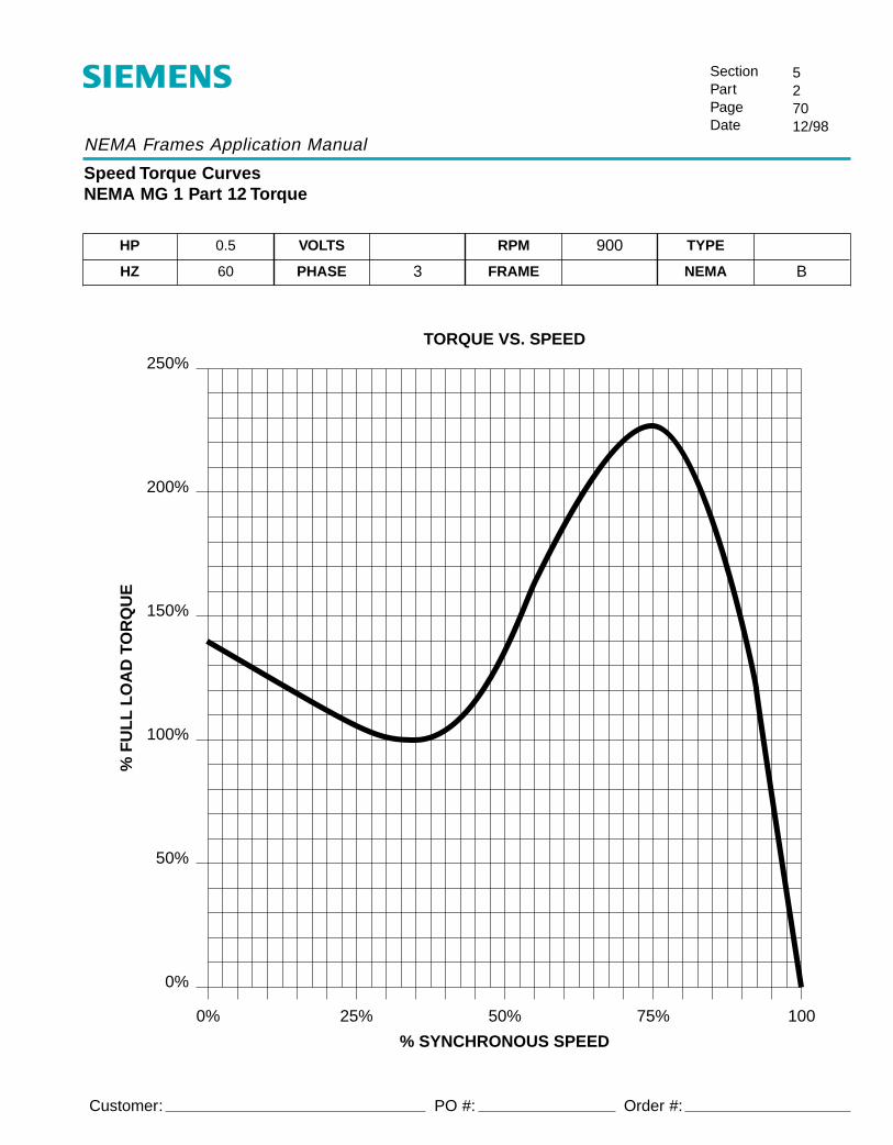
NEMA Frames Application Manual
Speed Torque CurvesNEMA MG 1 Part 12 Torque
SectionPartPageDate
527012/98
Customer:
HP 0.5 VOLTS RPM 900 TYPE
HZ 60 PHASE 3 FRAME NEMA B
TORQUE VS. SPEED250%
200%
150%
100%
50%
0%
0% 25% 50% 75% 100
% SYNCHRONOUS SPEED
% F
UL
L L
OA
D T
OR
QU
E
PO #: Order #:

NEMA Frames Application Manual
Speed Torque CurvesNEMA MG 1 Part 12 Torque
SectionPartPageDate
527112/98
Customer:
HP 0.75 VOLTS RPM 900 TYPE
HZ 60 PHASE 3 FRAME NEMA B
TORQUE VS. SPEED250%
200%
150%
100%
50%
0%
0% 25% 50% 75% 100
% SYNCHRONOUS SPEED
% F
UL
L L
OA
D T
OR
QU
E
PO #: Order #:

NEMA Frames Application Manual
Speed Torque CurvesNEMA MG 1 Part 12 Torque
SectionPartPageDate
527212/98
Customer:
HP 1 VOLTS RPM 900 TYPE
HZ 60 PHASE 3 FRAME NEMA B
TORQUE VS. SPEED250%
200%
150%
100%
50%
0%
0% 25% 50% 75% 100
% SYNCHRONOUS SPEED
% F
UL
L L
OA
D T
OR
QU
E
PO #: Order #:

NEMA Frames Application Manual
Speed Torque CurvesNEMA MG 1 Part 12 Torque
SectionPartPageDate
527312/98
Customer:
HP 1.5 VOLTS RPM 900 TYPE
HZ 60 PHASE 3 FRAME NEMA B
TORQUE VS. SPEED250%
200%
150%
100%
50%
0%
0% 25% 50% 75% 100
% SYNCHRONOUS SPEED
% F
UL
L L
OA
D T
OR
QU
E
PO #: Order #:

NEMA Frames Application Manual
Speed Torque CurvesNEMA MG 1 Part 12 Torque
SectionPartPageDate
527412/98
Customer:
HP 2 VOLTS RPM 900 TYPE
HZ 60 PHASE 3 FRAME NEMA B
TORQUE VS. SPEED250%
200%
150%
100%
50%
0%
0% 25% 50% 75% 100
% SYNCHRONOUS SPEED
% F
UL
L L
OA
D T
OR
QU
E
PO #: Order #:
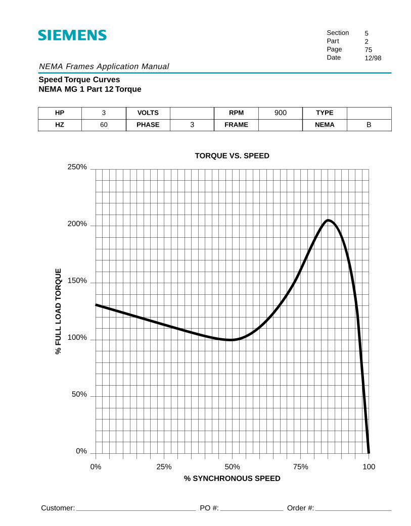
NEMA Frames Application Manual
Speed Torque CurvesNEMA MG 1 Part 12 Torque
SectionPartPageDate
527512/98
Customer:
HP 3 VOLTS RPM 900 TYPE
HZ 60 PHASE 3 FRAME NEMA B
TORQUE VS. SPEED250%
200%
150%
100%
50%
0%
0% 25% 50% 75% 100
% SYNCHRONOUS SPEED
% F
UL
L L
OA
D T
OR
QU
E
PO #: Order #:

NEMA Frames Application Manual
Speed Torque CurvesNEMA MG 1 Part 12 Torque
SectionPartPageDate
527612/98
Customer:
HP 5 VOLTS RPM 900 TYPE
HZ 60 PHASE 3 FRAME NEMA B
TORQUE VS. SPEED250%
200%
150%
100%
50%
0%
0% 25% 50% 75% 100
% SYNCHRONOUS SPEED
% F
UL
L L
OA
D T
OR
QU
E
PO #: Order #:

NEMA Frames Application Manual
Speed Torque CurvesNEMA MG 1 Part 12 Torque
SectionPartPageDate
527712/98
Customer:
HP 7.5 VOLTS RPM 900 TYPE
HZ 60 PHASE 3 FRAME NEMA B
TORQUE VS. SPEED
0%
20%
40%
60%
80%
100%
120%
140%
160%
180%
200%
0% 25% 50% 75% 100
% SYNCHRONOUS SPEED
% F
UL
L L
OA
D T
OR
QU
E
PO #: Order #:

NEMA Frames Application Manual
Speed Torque CurvesNEMA MG 1 Part 12 Torque
SectionPartPageDate
527812/98
Customer:
HP 10 VOLTS RPM 900 TYPE
HZ 60 PHASE 3 FRAME NEMA B
TORQUE VS. SPEED
0%
20%
40%
60%
80%
100%
120%
140%
160%
180%
200%
0% 25% 50% 75% 100
% SYNCHRONOUS SPEED
% F
UL
L L
OA
D T
OR
QU
E
PO #: Order #:

NEMA Frames Application Manual
Speed Torque CurvesNEMA MG 1 Part 12 Torque
SectionPartPageDate
527912/98
Customer:
HP 15 VOLTS RPM 900 TYPE
HZ 60 PHASE 3 FRAME NEMA B
TORQUE VS. SPEED
0%
20%
40%
60%
80%
100%
120%
140%
160%
180%
200%
0% 25% 50% 75% 100
% SYNCHRONOUS SPEED
% F
UL
L L
OA
D T
OR
QU
E
PO #: Order #:
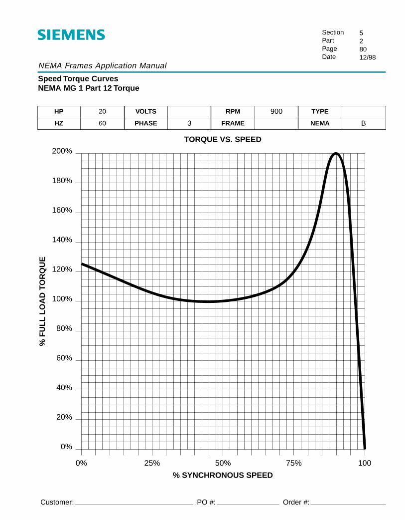
NEMA Frames Application Manual
Speed Torque CurvesNEMA MG 1 Part 12 Torque
SectionPartPageDate
528012/98
Customer:
HP 20 VOLTS RPM 900 TYPE
HZ 60 PHASE 3 FRAME NEMA B
TORQUE VS. SPEED
0%
20%
40%
60%
80%
100%
120%
140%
160%
180%
200%
0% 25% 50% 75% 100
% SYNCHRONOUS SPEED
% F
UL
L L
OA
D T
OR
QU
E
PO #: Order #:

NEMA Frames Application Manual
Speed Torque CurvesNEMA MG 1 Part 12 Torque
SectionPartPageDate
528112/98
Customer:
HP 25 VOLTS RPM 900 TYPE
HZ 60 PHASE 3 FRAME NEMA B
TORQUE VS. SPEED
0%
20%
40%
60%
80%
100%
120%
140%
160%
180%
200%
0% 25% 50% 75% 100
% SYNCHRONOUS SPEED
% F
UL
L L
OA
D T
OR
QU
E
PO #: Order #:

NEMA Frames Application Manual
Speed Torque CurvesNEMA MG 1 Part 12 Torque
SectionPartPageDate
528212/98
Customer:
HP 30 VOLTS RPM 900 TYPE
HZ 60 PHASE 3 FRAME NEMA B
TORQUE VS. SPEED
0%
20%
40%
60%
80%
100%
120%
140%
160%
180%
200%
0% 25% 50% 75% 100
% SYNCHRONOUS SPEED
% F
UL
L L
OA
D T
OR
QU
E
PO #: Order #:

NEMA Frames Application Manual
Speed Torque CurvesNEMA MG 1 Part 12 Torque
SectionPartPageDate
528312/98
Customer:
HP 40 VOLTS RPM 900 TYPE
HZ 60 PHASE 3 FRAME NEMA B
TORQUE VS. SPEED
0%
20%
40%
60%
80%
100%
120%
140%
160%
180%
200%
0% 25% 50% 75% 100
% SYNCHRONOUS SPEED
% F
UL
L L
OA
D T
OR
QU
E
PO #: Order #:

NEMA Frames Application Manual
Speed Torque CurvesNEMA MG 1 Part 12 Torque
SectionPartPageDate
528412/98
Customer:
HP 50 VOLTS RPM 900 TYPE
HZ 60 PHASE 3 FRAME NEMA B
TORQUE VS. SPEED
0%
20%
40%
60%
80%
100%
120%
140%
160%
180%
200%
0% 25% 50% 75% 100
% SYNCHRONOUS SPEED
% F
UL
L L
OA
D T
OR
QU
E
PO #: Order #:

NEMA Frames Application Manual
Speed Torque CurvesNEMA MG 1 Part 12 Torque
SectionPartPageDate
528512/98
Customer:
HP 60 VOLTS RPM 900 TYPE
HZ 60 PHASE 3 FRAME NEMA B
TORQUE VS. SPEED
0%
20%
40%
60%
80%
100%
120%
140%
160%
180%
200%
0% 25% 50% 75% 100
% SYNCHRONOUS SPEED
% F
UL
L L
OA
D T
OR
QU
E
PO #: Order #:

NEMA Frames Application Manual
Speed Torque CurvesNEMA MG 1 Part 12 Torque
SectionPartPageDate
528612/98
Customer:
HP 75 VOLTS RPM 900 TYPE
HZ 60 PHASE 3 FRAME NEMA B
TORQUE VS. SPEED
0%
20%
40%
60%
80%
100%
120%
140%
160%
180%
200%
0% 25% 50% 75% 100
% SYNCHRONOUS SPEED
% F
UL
L L
OA
D T
OR
QU
E
PO #: Order #:

NEMA Frames Application Manual
Speed Torque CurvesNEMA MG 1 Part 12 Torque
SectionPartPageDate
528712/98
Customer:
HP 100 VOLTS RPM 900 TYPE
HZ 60 PHASE 3 FRAME NEMA B
TORQUE VS. SPEED
0%
20%
40%
60%
80%
100%
120%
140%
160%
180%
200%
0% 25% 50% 75% 100
% SYNCHRONOUS SPEED
% F
UL
L L
OA
D T
OR
QU
E
PO #: Order #:

NEMA Frames Application Manual
Speed Torque CurvesNEMA MG 1 Part 12 Torque
SectionPartPageDate
528812/98
Customer:
HP 125 VOLTS RPM 900 TYPE
HZ 60 PHASE 3 FRAME NEMA B
TORQUE VS. SPEED
0%
20%
40%
60%
80%
100%
120%
140%
160%
180%
200%
0% 25% 50% 75% 100
% SYNCHRONOUS SPEED
% F
UL
L L
OA
D T
OR
QU
E
PO #: Order #:

NEMA Frames Application Manual
Speed Torque CurvesNEMA MG 1 Part 12 Torque
SectionPartPageDate
528912/98
Customer:
HP 150 VOLTS RPM 900 TYPE
HZ 60 PHASE 3 FRAME NEMA B
TORQUE VS. SPEED
0%
20%
40%
60%
80%
100%
120%
140%
160%
180%
200%
0% 25% 50% 75% 100
% SYNCHRONOUS SPEED
% F
UL
L L
OA
D T
OR
QU
E
PO #: Order #:

NEMA Frames Application Manual
Speed Torque CurvesNEMA MG 1 Part 12 Torque
SectionPartPageDate
529012/98
Customer:
HP 200 VOLTS RPM 900 TYPE
HZ 60 PHASE 3 FRAME NEMA B
TORQUE VS. SPEED
0%
20%
40%
60%
80%
100%
120%
140%
160%
180%
200%
0% 25% 50% 75% 100
% SYNCHRONOUS SPEED
% F
UL
L L
OA
D T
OR
QU
E
PO #: Order #:

NEMA Frames Application Manual
Speed Torque CurvesNEMA MG 1 Part 12 Torque
SectionPartPageDate
529112/98
Customer:
HP 250 VOLTS RPM 900 TYPE
HZ 60 PHASE 3 FRAME NEMA B
TORQUE VS. SPEED
0%
20%
40%
60%
80%
100%
120%
140%
160%
180%
0% 25% 50% 75% 100
% SYNCHRONOUS SPEED
% F
UL
L L
OA
D T
OR
QU
E
PO #: Order #:
NMSA-L1000
RGZESDI Application ManualInverter Duty AC Induction Motors
App Manual in Spreads 1/16/01 9:03 AM Page 3

2
General Information
Application Considerations . . . . . . . . . . . . . . . .3, 7Warranty . . . . . . . . . . . . . . . . . . . . . . . . . . . . . . . 4Insulation . . . . . . . . . . . . . . . . . . . . . . . . . . . . . 4, 6Background . . . . . . . . . . . . . . . . . . . . . . . . . . . . . 5Understanding IGBT Drives . . . . . . . . . . . . . . . . . 5Motor Design . . . . . . . . . . . . . . . . . . . . . . . . . . . . 6Output Reactors/Cable Considerations . . . . . . . . . 7Refer to Performance Curves . . . . . . . . . . . . . . . . 8Notes . . . . . . . . . . . . . . . . . . . . . . . . . . . . . . . . .33
Performance Curves
Volts/Hz Control Drive2 pole . . . . . . . . . . . . . . . . . . . . . . . . . . . . 9 - 134 pole . . . . . . . . . . . . . . . . . . . . . . . . . . . 14 - 186 pole . . . . . . . . . . . . . . . . . . . . . . . . . . . 19 - 238 pole . . . . . . . . . . . . . . . . . . . . . . . . . . . .24 - 27RGZZESD Inverter Duty . . . . . . . . . . . . . . .34 - 35
Motor Selection Guide
Variable/Constant Torque . . . . . . . . . . . . . 28 - 291000:1 Constant Torque . . . . . . . . . . . . . . 30 - 31RGZZESD Inverter Duty . . . . . . . . . . . . . . . . . 32
Related Catalogs and Information
Inverter Duty Selection and Pricing Guide . . . . . . . . . . . . . . . . . . . . . . . . . . . . . . . . . . . . . . . . . . . . . . . . . . . . . . . Bulletin NMSP L0700A
MedallionSelection and Pricing Guide . . . . . . . . . . . . . . . . . . . . . . . . . . . . . . . . . . . . . . . . . . . . . . . . . . . . . . . Bulletin NMSP-L0500A
RGZESDI Inverter Duty AC Induction MotorsInstallation • Operation • Maintenance Instructions . . . . . . . . . . . . . . . . . . . . . . . . . . . . . . . . . . . . . . . Bulletin NMIM-L1000
Stocked Low Voltage IEC MotorsSelection and Pricing Guide. . . . . . . . . . . . . . . . . . . . . . . . . . . . . . . . . . . . . . . . . . . . . . . . . . . . . . . . . Bulletin NMSP-L0200
TABLE OF CONTENTS
Data subject to change without notice.
App Manual in Spreads 1/16/01 9:03 AM Page 4

GENERAL INFORMATION
As a manufacturer of both variablespeed drives and AC motors,Siemens has a superior understand-ing of their collective operation,application, and performance. TheInverter Duty Motors outlined inthis publication are the result of anextensive testing program to estab-lish guidelines for their typical uti-lization.
Siemens inverter-duty motors arerated for continuous operation in a40° C ambient at altitudes up to3300 feet above sea level. For spe-cialized applications, such as non-standard ambient, intermittent orhigh duty cycles, high constanthorsepower speed ranges (higherthan those indicated), non-standardvoltage or frequency, or other spe-cial conditions, please consultSiemens.
APPLICATION CONSIDERATIONS
Variable Torque Applications -From the perspective of motorcooling, AC motors are well suitedto be used in adjustable speedvariable torque applications, suchas centrifugal fans or pumps. Thetorque characteristics of a variabletorque load is such that the loadfalls off rapidly as the motor speedis reduced. The variable torqueload eliminates the necessity tode-rate the motor due to excessiveheat resulting from diminishedmotor cooling at reduced speeds.Variable Torque operation abovebase speed must be reviewed bySiemens.
Constant Torque Operation -Many general industrial machines,other than fans and pumps, areconstant torque systems where themachine’s torque requirement isindependent of its speed. If themachine speed is doubled, itshorsepower requirement doubles.
Vector drives can supply nearlyideal conditions to the motor result-ing in better motor performance,cooler operation, and more precisespeed regulation, especially at lowspeed ranges. A standard 4-pole460V motor can be accurately con-trolled by this method to its syn-chronous speed of 1800 RPM.
RGZESDI Constant Torque motorsprovide full rated torque within theirlisted speed range, without exceed-ing their Class F temperature ratingon PWM (pulse width modulated)inverter power. Ratings in this cat-alog are based on use with vectortype IGBT inverters, set at a mini-mum 3 kHz switching frequency,and are designed for operation at150% of rated torque for oneminute, up to the base speed ofthe motor (overload capacitydeclines as the motor reaches max-imum speed).
Constant Torque operation abovebase speed must be reviewed bySiemens.
Constant Horsepower Operation -AC motor controllers are also adapt-able to constant horsepower opera-tion. With this mode of operation,the Volts/Hz ratio is maintained to aspecific frequency, normally 60 Hz.At this point, the voltage is“clamped” at a constant level while
the frequency is adjusted further toachieve the desired maximumspeed. The motor becomes “volt-age starved” above the clampingpoint and torque decreases asspeed increases, resulting in con-stant horsepower output. In con-stant horsepower applications, thedrive provides conventional constanttorque/variable horsepower opera-tion up to 60 hertz. Above 60 hertz,the motor/drive provides constanthorsepower, variable torque opera-tion.
Constant Horsepower Speed Limits (see pg 28-29 chart)
Maximum Safe MechanicalSpeed Limits Direct Connected Loads(Does not imply constant horse-power capability)
3
Caution must be observed when applying standard motors for continuous low speed, constant torque opera-tion. A standard motor’s self-cooling capacity depends upon self-ventilation schemes that are greatly reducedat decreased operating speeds.
CAUTION
Motor 3600 1800 1200 900 Frame RPM RPM RPM RPM
143-184 5400 3600 2400 1800213-256 5400 3600 2400 1800284-286 4800 3000 2000 1500324-326 4800 3000 2000 1500364-365 4500 2700 1800 1350404-405 3600 2700 1800 1350444-445* 3600 2700 1800 1350447-449* 3600 2400 1800 1350
*444-449 frame motors (1800 RPM andbelow) intended for belt duty are sup-plied with roller bearings. Consultsheave/belt supplier for maximum safeoperating speeds.
Motor 3600 1800 1200 Frame RPM RPM RPM
143-184 7200 5400 2700213-256 5400 4200 2700284-286 5400 3600 2700324-326 4500 3600 2700364-365 4500 2700 2700404-445 3600 2700 1800447-449 3600 2250 1800
App Manual in Spreads 1/16/01 9:03 AM Page 7

4
WARRANTY
Siemens totally enclosed RGZESDIand explosion proof RGZZESDinverter-duty motors are warrantedto be free from defects in materialsand workmanship for a period ofthirty-six (36) months from the dateof manufacture. See also“Siemens Standard Terms andConditions of Sale” for additionaldetails.
ServiceFor warranty service on thesemotors, contact your nearestSiemens authorized service shop.
AccessoriesAccessories, such as “C” face kitsor encoders, can be added to stockmotors in our Super Mod Center.Other common modifications, suchas addition of space heaters, shaftseals or change to F2 assembly, arealso available from the Super ModCenter. This facility provides ashort lead-time on many popularmodifications.
Optional BlowersLow rotational speeds at constanttorque loads, common in many vec-tor applications, provide the motorwith reduced ventilation. As aresult, these motors are designedas Totally Enclosed Blower Cooled.Blowers are powered by a SiemensTENV, Severe Duty, 3 phase motor.Standard voltage is 230/460.
Optional EncodersThese electronic devices senserotor speed and direction. A cableis connected from the encoder tothe VFD. Various resolutions (puls-es per revolution, PPR) are avail-able. All encoders offer quadrature(direction sensing), with line driveroutput.
Service FactorStandard service factor for RGZES-DI motors is 1.0 on inverter power.RGZESDI motors are suitable for1.15 service factor on sine wavepower.
Thermal ProtectionAll RGZESDI motors are equippedwith Class F normally closed ther-mostats for detection of overloadconditions and/or excessive heat-ing.
InsulationType RGZESDI inverter dutymotors utilize an insulation systemdesigned to meet the requirementsof NEMA Part 31.
50 Hertz PowerOperation on 50 Hz sources limitsthe speed and voltage available fortorque. Typically the next strongermotor, in larger frame is requiredfor satisfactory application and per-formance.
It is the responsibility of the startup personnel during commissioning of the VFD/motor combination to proper-ly tune the drive to the motor for the specific application. Application of motors which are not per the guide-lines of this document may void the warranty, if they are not specifically approved by Siemens.
CAUTION
App Manual in Spreads 1/16/01 9:03 AM Page 8
5
BACKGROUND
More and more electric motors arebeing used with variable frequencydrives (VFD) powered by insulatedgate bipolar transistors or IGBT’s.Typical considerations for loadtorque characteristics and lowspeed operation remain importantin specifying a motor to ensureadequate cooling, but IGBT drivescan introduce other elements. Dueto the rapid switching rates of IGBTdrives, the potential for long termdetrimental effects on motor insula-tion exists if special measures arenot taken. IGBT based PWM(pulse width modulated) drives gen-erate high voltage spikes due totheir high carrier frequencies andthe short rise-time of their pulsedoutputs.
In response to these concerns,Siemens has conducted researchand testing to better understandthe voltage stress environment inwhich our insulation system isexpected to perform. The insula-tion system offered in the RGZES-DI is designed and manufactured tooperate with a variable frequencydrive (VFD) for long motor life, highreliability, and superior perfor-mance.
UNDERSTANDING IGBT DRIVES
IGBT’s have become the preferredpower-switching device in moderndrives because of their low costand relative ease of manufacture.In addition, their high switchingspeed reduces losses while creat-ing better motor current waveformsand improved overall dynamic per-formance as compared to earliertechnologies. Most conventionalvoltage source VFD’s rectify thesinusoidal AC voltage provided bythe power utility and use switches(IGBTs) to create a pulse width modulated output (PWM).The drive sends out a train of rec-tangular shaped pulses to themotor via the motor lead cables.The height of the pulses is equal tothe DC bus voltage.
Their widths and spacing, however,are varied or modulated in such away as to provide an effective volt-age similar to a sinusoidal voltageof the desired magnitude and fre-quency.
The drive sends out these pulses ata rate equal to the control carrierfrequency. Modern VFD’s typicallyutilize carrier frequencies in a rangefrom 2-20 kHz meaning that thedrive may be sending out as manyas 20,000 pulses per second.
IGBTs used to produce these volt-age pulses have very short turn onand turn off times and therefore,the pulses have very short rise andfall times. Rise time is defined inNEMA MG 1 Part 30 as the timerequired for the pulse to go from10% to 90% of its steady statevalue. Today’s VFD’s produce puls-es with rise times as low as .05microseconds.
Voltage Spikes or Overshoots:Because of the IGBT’s rapid risetime, a transient over-voltage oftwice the DC bus voltage (or higherunder unusual conditions) can occureach time a pulse reaches themotor terminals.
Several variables can affect themagnitude of the transient over-voltage including pulse rise timeand magnitude; spacing of pulses;cable length; and motor and cablesurge impedance. Installations hav-ing relatively small drives on longcables require added precautions,not only to assure the motor insula-tion is not over-stressed, but toalso assure proper operation of theinverter.
Neutral Shift: Neutral shift is thevoltage difference between thethree-phase power source neutralof the VFD and the motor neutral.Its magnitude is a function of thetotal system design. The result ofneutral shift is higher than normalline to ground voltages at themotor. In the case of typical volt-age source drive, it can be as highas the DC bus voltage value, evenwithout considering transient over-voltages.
Including transient over-voltages,the motor may be exposed to apeak line to ground voltage of 1.5to 2 times the DC bus voltage.(Refer to NEMA MG1-Part 31.4.4.4.)
The RGZESDI Insulation System
App Manual in Spreads 1/16/01 9:03 AM Page 11

6
The RGZESDI Insulation SystemRandom-wound motor insulationcomponents consist of stator wireinsulation, phase insulation, slot orground insulation, and impregnatingvarnish. These components mustbe carefully chosen for motorsintended for use with adjustablespeed drives, because of the fac-tors outlined earlier. The RGZESDImotor uses an insulation systemsuitable for most common VFDapplications.
Turn Insulation: As stated earlier,transient over-voltages can elevatethe motor line-to-line voltage ashigh as twice the control DC busvoltage. The steep-fronted nature(rapid rise time or dv/dt) of thesepulses cause them to be unevenlydistributed throughout the winding.Thus, the first coil is exposed tohigher voltages than the rest of thewinding. This is why motors thatare improperly applied to VFD’s canbe expected to fail most oftenacross this first coil.
Unfortunately, with random wind-ings, the first and last turn in a coilare sometimes placed near oneanother in the slot. This causes theentire coil voltage to be presentbetween these two adjacent wires.When two conductors have a volt-age between them, it becomes dis-tributed within the insulation and inthe air between their surfaces. Ifthe voltage gradient in the air spacebetween these conductors isbeyond a certain critical value, aluminous discharge will take placedue to the ionization of air. Thisdischarge is known as corona (par-tial discharge). The critical voltageat which corona begins to takeplace is known as the corona incep-tion voltage CIV. In order to obtainlong motor service life, coronamust be avoided as much as possi-ble. However, simply avoidingcorona is not enough to assure longlife. Siemens has collected exten-sive data regarding the voltagepulse endurance characteristics ofvarious magnet wire insulations,along with a detailed understandingof how the voltage pulses are dis-tributed throughout the motor.
Armed with this information ourengineers have designed theRGZESDI using a winding layoutand wire type such that the expect-ed voltage between any two wiresis safely below a value that wouldresult in unacceptable insulationlife.
There are several insulationenhancements in the RGZESDI thatoffer reliable performance in invert-er applications. Among them areimproved wire film; optimized spac-ing of the insulation; low operatingtemperature; and use of our uniquenon-hygroscopic insulation systemfor superior resistance to theeffects of humidity. Small air bub-bles in the insulation have beennearly eliminated and crevicesbetween adjacent turns have beenminimized during varnishing.Siemens quality processes mini-mize the likelihood for these areasto become sites for partial dis-charges and accelerated insulationfailure.
Phase Insulation: Phase insulationconsists of slot center insulationand phase barrier insulation. Theslot center insulation separates thetop and bottom coils in a two layerthree-phase winding. The phasebarrier insulation is insertedbetween coils belonging to differ-ent phases in the winding endturns. Because of the high phase-to-phase voltages that are possibleduring operation from a PWM con-trol, the thickness of these compo-nents has been increased over thatutilized for sine wave operation.
Slot or ground insulation: As dis-cussed earlier because of neutralshift and transient over-voltages,the ground insulation can be moreseverely stressed in VFD than insine wave applications. For thisreason ground insulation thicknesshas also been increased.
NEMA MG1-Part 31.4.4.2.
NEMA MG1, Parts 30 and 31 out-line motor capabilities when usedwith VFD’s for motors rated 600volts or less. Part 30 requires thatstandard motors utilize an insulationsystem able to endure repeatedvoltage peaks of up to 1000 voltswith rise times of 2 or moremicroseconds. Part 31 defines aninverter duty motor as having aninsulation system able to withstandpeaks of 3.1 times rated voltagewith rise times of 0.1 or moremicrosecond. The RGZESDI motor, speciallydesigned for inverter duty applica-tions, exceeds the insulation criteriaspecified NEMA MG 1, Part 31 andcan be specified when a superiorinsulation is needed. As a manufac-turer of both variable speed drivesand AC motors, Siemens has asuperior understanding of their col-lective operation, application, andperformance.
MOTOR DESIGN
For a motor to be reliable in invert-er duty applications it should bedesigned to keep internal operatingtemperatures at a minimum.Rotors should be free from voids tominimize current-flow resistanceand excess heat generation.
The Siemens 4-Quadrant fin coolingdesign maximizes heat dissipation,and fans and blowers have beenoptimized for reliable ventilation.Tight tolerances and good mechani-cal contact guarantee thermal con-tact to external cooling surfaces. Abuilt-in thermostat acts as an addedmeasure against heat buildup orinadequate cooling.
The mechanical features of theRGZESDI make certain the motorwill perform in the most demandingapplications. Low vibration, castiron construction - including castiron inner bearing caps on all framesizes - and Siemens dedication toquality, assure that every RGZESDIwill provide reliable operation usedwith modern inverter power.
App Manual in Spreads 1/16/01 9:03 AM Page 12

7
APPLICATION CONSIDERATIONS• Leave the commissioning of the VFD/motor combination to experienced startup personnel.
• Connect the thermostat leads to the control or alarm circuit of the VFD or control circuit.
• Connect the blower (if so equipped) per the wiring diagram supplied with the blower motor.
• Connect the encoder (if so equipped) per the wiring diagram supplied with the encoder.
• Refer any special applications (high or low ambient, high cyclic loading, special voltage or frequen-cy, etc.) to Siemens.
• Specify an inverter with a carrier frequency selectable to a minimum of 3 KHz.
• Read the instruction manual supplied with the motor and VFD before applying power to the combi-nation.
• Do not operate RGZESDI motors beyond 1.0 service factor on inverter power.
• Obtain the consent of Siemens Warranty Administration before performing any repair during thefirst 36 months of operation.
• Do not place power factor correction capacitors between the motor and VFD.
• Do not exceed speed parameters specified on the motor nameplate.
• Do not utilize excessively long cable lengths between the drive and motor. (See guidelines below.)
Output Reactors/Cable ConsiderationsThe output reactor is especiallyused to limit additional currentspikes caused by the cable capaci-tances when long cables are used,i.e., it:
• Reduces the charge currentspikes for long cables
• Reduces the voltage rate-of-change dv/dt at the motor termi-nals.
It does not reduce the magnitudeof the transient voltage spikes atthe motor terminals.
NOTEThe specified lengths are valid forunshielded cables; for shieldedcables, these values must bereduced to 2/3.If several motors are connected toa drive converter, the sum of thecables lengths of all the motorfeeder cables must be less thanthe permissible cable length.
App Manual in Spreads 1/16/01 9:03 AM Page 15

8
The purpose of the calculationsbelow is to determine pull-uptorque and pull-up speed and plotthese points on the curves provid-ed. If these points fall beneath thecurves, then acceptable applicationresults.
SpeedL = actual RPMnameplate RPM
TorqueL = actual torque = actual HPrated torque rated HP
Rated = nameplate HP X 5252torque nameplate RPM
Constant Horsepower
For constant horsepower loads, thetorque is proportional to the speed.The equation to calculate pull-uptorque is:
= (pull-up RPMold) X (pull-up torque old)(pull-up RPMnew)
Calculate torque for each of theknown speed points and plot thesepoints on the attached graphs. Ifany point falls above the curve, themotor will overheat when usedwith a variable frequency drive forthe type of load identified.
Constant Torque
For constant torque loads, wherethe calculated value of pull-uptorque can be used for all speeds.
Example 1 - Constant TorqueLoads
• 4 pole• 100 horsepower• Constant torque to 20 Hz speed• 84 HP at nameplate RPM
(see curves page 17)
Point 11800 RPM @ 60 Hz
Torque = 84 x 295 = 248100
Point 2600 RPM @ 20 Hz
Torque still 248
Since both points fall beneath thecurve for a 4 pole 100 hp motor,this motor will function properlyunder VFD power for the applica-tion described.
Variable Torque
For variable torque loads, thetorque is proportional to the squareof the speed. The equation to cal-culate pull-up torque is:
= (RPMnew)2 X (Torqueold)(RPMold)2
Example 2 - Variable Torque
• 6 pole• 50 horsepower• 100 lb-ft load torque at 1180
RPM• Variable torque down to zero
speed(see curves page 22)
Since torque varies as a square ofthe speed, only the highest speedpoint needs to be checked.
HzL= actual RPM x 60 = 1180 x 60 = 60 nameplate RPM 1180
Rated torque = (rated HP)X(5252) =rated RPM
= (50) (5252) = 2231180
TorqueL =actual = 100 lb-ft torque
Since the highest speed point onthis variable torque falls beneaththe line, this motor will functionproperly under VFD power for theapplication described.
Refer to Performance Curves
The attached curves are provided to determine thesuitability of type RGZESDI for applications with pulsewidth modulated (PWM) variable frequency drives.These curves apply only to Siemens type RGZESDImotors listed in Selection and Pricing Guide NMSP-L0700A. If the desired motor cannot be selected fromthe curves provided, refer the application to Siemens.Explosion proof motors can be applied in accordanceto the curves on pages 30 and 31.
Information Needed for Motor Selection
Operating Speed Range: Minimum and maximumspeeds must be determined prior to the selection ofthe motor. If operation is required above base speed(60 hertz rated speed), first ensure that constanthorsepower (CHP) speeds are not exceeded.
Type of Load: Select from Variable Torque, ConstantTorque, or Constant Horsepower.
App Manual in Spreads 1/16/01 9:03 AM Page 16

9
2-P
ole
1.5
- 5
HP
TORQUE (FT LB)
HE
RT
Z
010
20
30
40
50
60
70
80
100
90
01468
TO
RQ
UE
vs F
RE
QU
EN
CY
2 H
P
3 H
P
5 H
P
1.5
HP
7 5 23
INT
ER
MIT
TE
NT
OP
ER
AT
ION
Su
ita
ble
fo
r 1
50
% o
f th
is t
orq
ue
FO
R O
NE
MIN
UT
E M
AX
IMU
M
App Manual in Spreads 1/16/01 9:03 AM Page 19
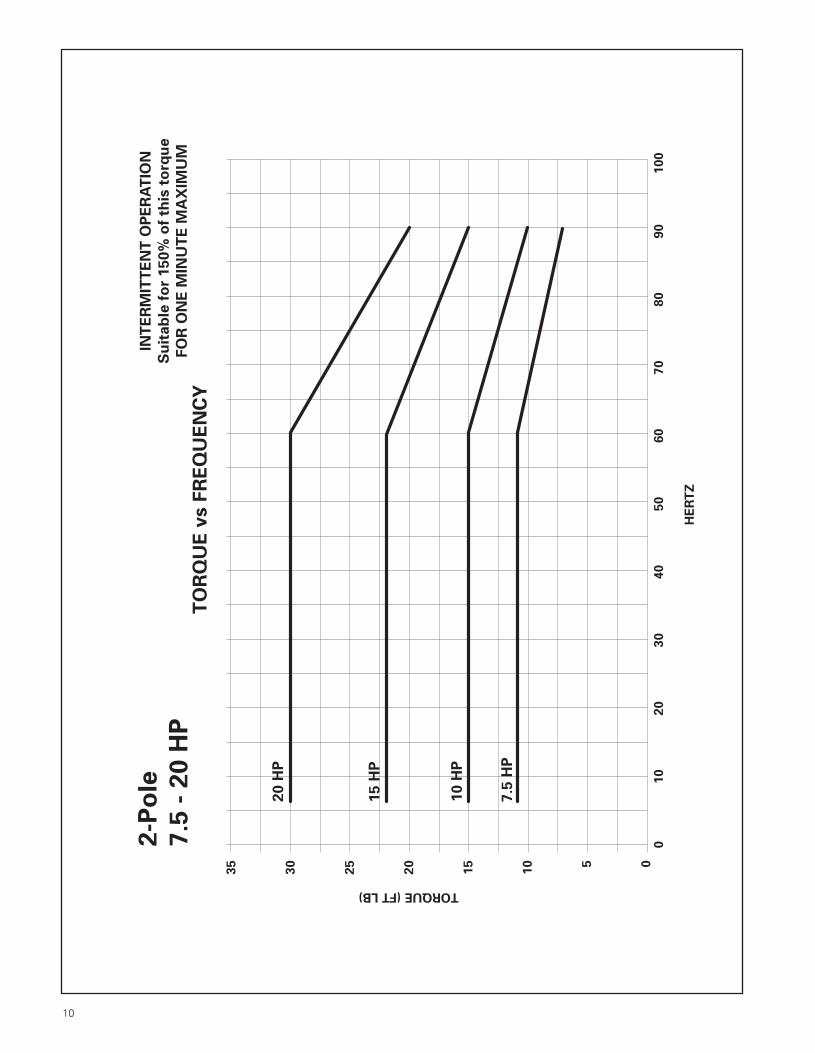
10
2-P
ole
7.5
- 2
0 H
PTORQUE (FT LB)
HE
RT
Z
010
20
30
40
50
60
70
80
100
90
05
20
30
TO
RQ
UE
vs F
RE
QU
EN
CY
10
HP
15
HP
20
HP
7.5
HP
35
25
10
15
INT
ER
MIT
TE
NT
OP
ER
AT
ION
Su
ita
ble
fo
r 1
50
% o
f th
is t
orq
ue
FO
R O
NE
MIN
UT
E M
AX
IMU
M
App Manual in Spreads 1/16/01 9:03 AM Page 20

11
2-P
ole
25
- 5
0 H
P
TORQUE (FT LB)
HE
RT
Z
010
20
30
40
50
60
70
80
90
0
20
40
60
80
TO
RQ
UE
vs F
RE
QU
EN
CY
25
HP
30
HP
40
HP
50
HP
70
50
30
10
INT
ER
MIT
TE
NT
OP
ER
AT
ION
Su
ita
ble
fo
r 1
50
% o
f th
is t
orq
ue
FO
R O
NE
MIN
UT
E M
AX
IMU
M
App Manual in Spreads 1/16/01 9:03 AM Page 23

12
2-P
ole
60
- 1
50
HP
TORQUE (FT LB)
HE
RT
Z
010
20
30
40
50
60
70
80
90
0
50
100
150
200
250
TO
RQ
UE
vs F
RE
QU
EN
CY
75
HP
10
0 H
P
12
5 H
P
60
HP
15
0 H
P
INT
ER
MIT
TE
NT
OP
ER
AT
ION
Su
ita
ble
fo
r 1
50
% o
f th
is t
orq
ue
FO
R O
NE
MIN
UT
E M
AX
IMU
M
App Manual in Spreads 1/16/01 9:03 AM Page 24

13
2-P
ole
20
0 -
40
0 H
P
TORQUE (FT LB)
HE
RT
Z
010
20
30
40
50
60
70
80
90
0
100
200
300
400
500
700
TO
RQ
UE
vs F
RE
QU
EN
CY
25
0 H
P
30
0 H
P
35
0 H
P
20
0 H
P
40
0 H
P600
INT
ER
MIT
TE
NT
OP
ER
AT
ION
Su
ita
ble
fo
r 1
50
% o
f th
is t
orq
ue
FO
R O
NE
MIN
UT
E M
AX
IMU
M
App Manual in Spreads 1/16/01 9:03 AM Page 27

14
4-P
ole
1-5
HP
TORQUE (FT LB)
028
12
16
TO
RQ
UE
vs F
RE
QU
EN
CY
4
2 H
P6
10
14
1.5
HP
5 H
P
HE
RT
Z
01
02
03
04
05
06
07
08
01
00
90
11
01
20
13
0
3 H
P
1 H
P
INT
ER
MIT
TE
NT
OP
ER
AT
ION
Su
itab
le f
or
150%
of
this
to
rqu
e
FO
R O
NE
MIN
UT
E M
AX
IMU
M
App Manual in Spreads 1/16/01 9:03 AM Page 28

15
4-P
ole
7.5
-20 H
P
TORQUE (FT LB)
0
10
40
60
TO
RQ
UE
vs F
RE
QU
EN
CY
20
10 H
P3
0
50
70
7.5
HP
15 H
P
20 H
P
HE
RT
Z
01
02
03
04
05
06
07
08
01
00
90
11
01
20
13
0
INT
ER
MIT
TE
NT
OP
ER
AT
ION
Su
itab
le f
or
150%
of
this
to
rqu
e
FO
R O
NE
MIN
UT
E M
AX
IMU
M
App Manual in Spreads 1/16/01 9:03 AM Page 31

16
4-P
ole
25
-50
HP
TORQUE (FT LB)
HE
RT
Z
0
20
80
120
160
TO
RQ
UE
vs F
RE
QU
EN
CY
40
30
HP
60
100
140
010
20
30
40
50
60
70
80
100
90
110
120
25
HP
40
HP
50
HP
INT
ER
MIT
TE
NT
OP
ER
AT
ION
Su
ita
ble
fo
r 1
50
% o
f th
is t
orq
ue
FO
R O
NE
MIN
UT
E M
AX
IMU
M
App Manual in Spreads 1/16/01 9:03 AM Page 32

17
4-P
ole
60
-15
0 H
P
TORQUE (FT LB)
HE
RT
Z
0
200
300
500
TO
RQ
UE
vs F
RE
QU
EN
CY
100
10
0H
P
010
20
30
40
50
60
70
80
100
90
110
120
75
HP
12
5 H
P
15
0 H
P
50
150
250
350
400
450
60
HP
INT
ER
MIT
TE
NT
OP
ER
AT
ION
Su
ita
ble
fo
r 1
50
% o
f th
is t
orq
ue
FO
R O
NE
MIN
UT
E M
AX
IMU
M
App Manual in Spreads 1/16/01 9:03 AM Page 35
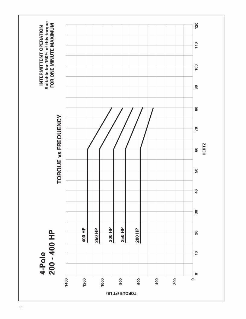
18
4-P
ole
20
0 -
40
0 H
P
TORQUE (FT LB)
HE
RT
Z
0
200
800
1200
TO
RQ
UE
vs F
RE
QU
EN
CY
40
0 H
P
400
35
0 H
P
25
0 H
P
20
0 H
P600
1000
1400
010
20
30
40
50
60
70
80
100
90
110
120
30
0 H
P
INT
ER
MIT
TE
NT
OP
ER
AT
ION
Su
ita
ble
fo
r 1
50
% o
f th
is t
orq
ue
FO
R O
NE
MIN
UT
E M
AX
IMU
M
App Manual in Spreads 1/16/01 9:03 AM Page 36
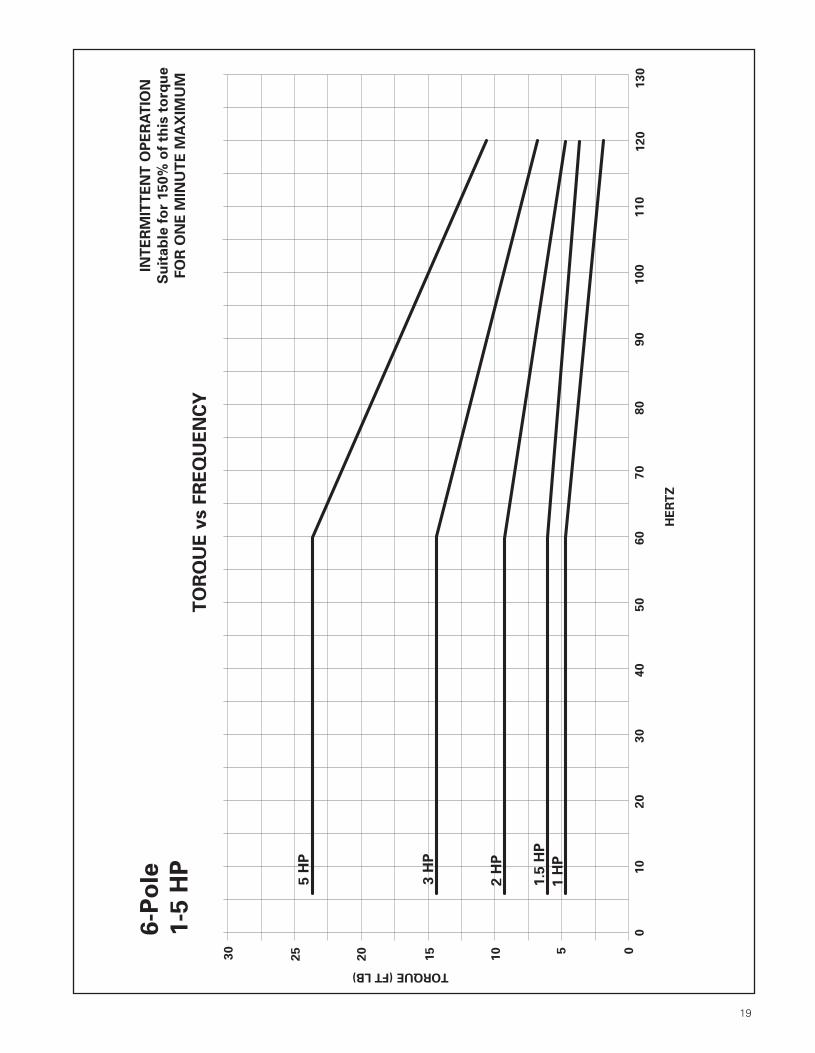
19
6-P
ole
1-5
HP
TORQUE (FT LB)
0
10
15
20
25
30
TO
RQ
UE
vs F
RE
QU
EN
CY
5
2 H
P
1.5
HP
5 H
P
HE
RT
Z
01
02
03
04
05
06
07
08
01
00
90
11
01
20
13
0
3 H
P
1 H
P
INT
ER
MIT
TE
NT
OP
ER
AT
ION
Su
itab
le f
or
150%
of
this
to
rqu
e
FO
R O
NE
MIN
UT
E M
AX
IMU
M
App Manual in Spreads 1/16/01 9:03 AM Page 37
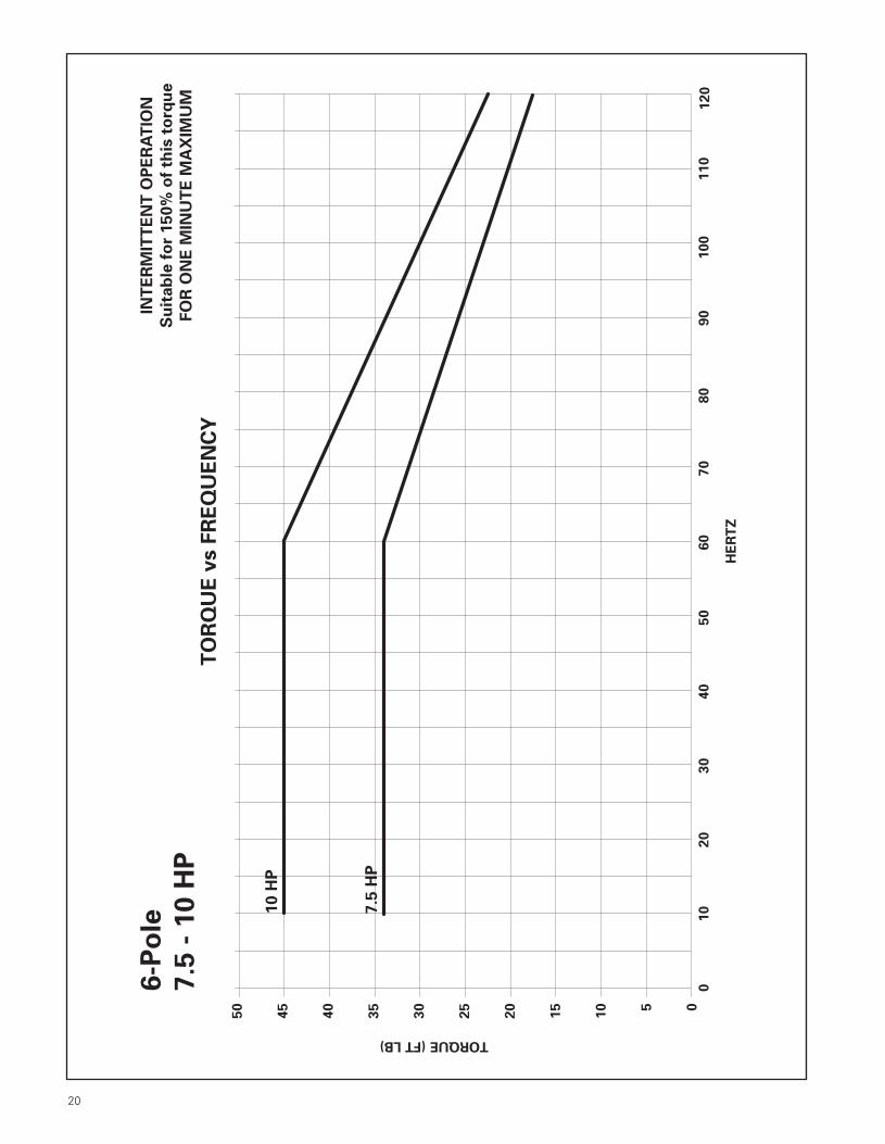
20
010
20
30
40
50
60
70
80
100
90
110
120
6-P
ole
7.5
- 1
0 H
P
TORQUE (FT LB)
HE
RT
Z
05
20
30
40
50
TO
RQ
UE
vs F
RE
QU
EN
CY
10
HP
45
10
7.5
HP
15
25
35
INT
ER
MIT
TE
NT
OP
ER
AT
ION
Su
ita
ble
fo
r 1
50
% o
f th
is t
orq
ue
FO
R O
NE
MIN
UT
E M
AX
IMU
M
App Manual in Spreads 1/16/01 9:03 AM Page 34

21
6-P
ole
15
- 3
0 H
P
TORQUE (FT LB)
HE
RT
Z
0
20
80
120
TO
RQ
UE
vs F
RE
QU
EN
CY
30
HP
40
25
HP
20
HP
15
HP
60
100
140
010
20
30
40
50
60
70
80
100
90
110
120
INT
ER
MIT
TE
NT
OP
ER
AT
ION
Su
ita
ble
fo
r 1
50
% o
f th
is t
orq
ue
FO
R O
NE
MIN
UT
E M
AX
IMU
M
App Manual in Spreads 1/16/01 9:03 AM Page 33
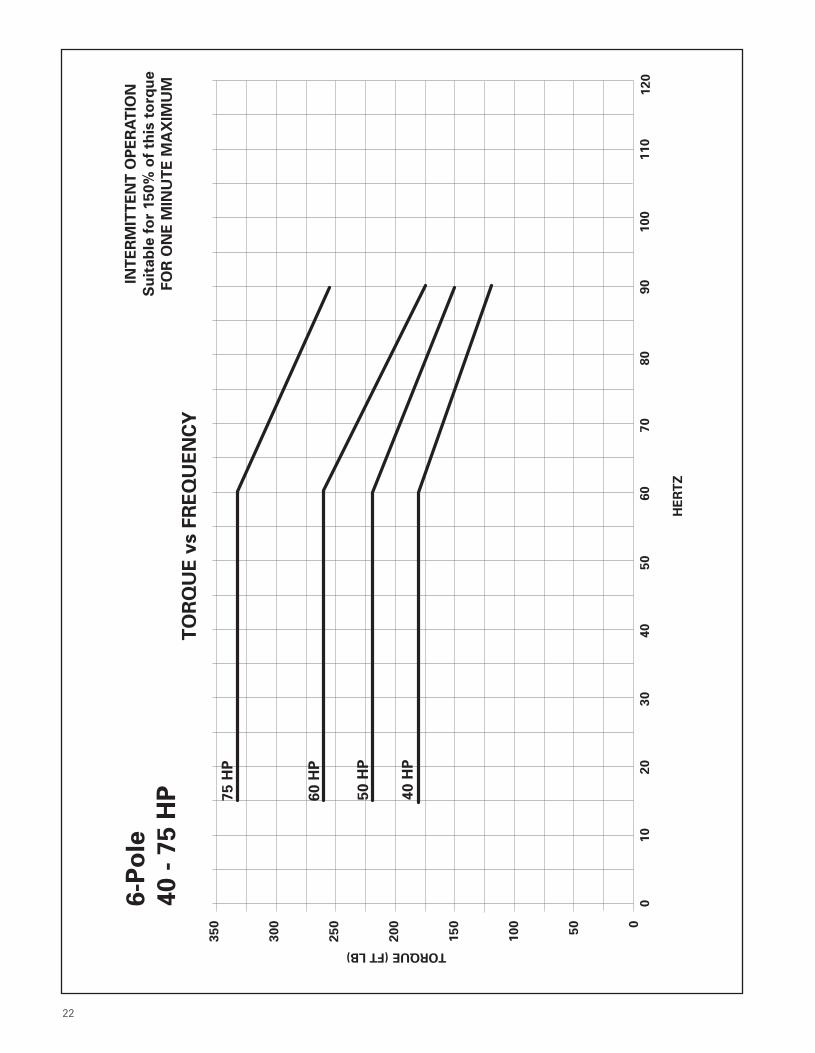
22
INT
ER
MIT
TE
NT
OP
ER
AT
ION
Su
ita
ble
fo
r 1
50
% o
f th
is t
orq
ue
FO
R O
NE
MIN
UT
E M
AX
IMU
M
6-P
ole
40
- 7
5 H
P
TORQUE (FT LB)
HE
RT
Z
0
50
200
300
TO
RQ
UE
vs F
RE
QU
EN
CY
75
HP
350
250
100
150
60
HP
50
HP
40
HP
010
20
30
40
50
60
70
80
100
90
110
120
App Manual in Spreads 1/16/01 9:03 AM Page 30
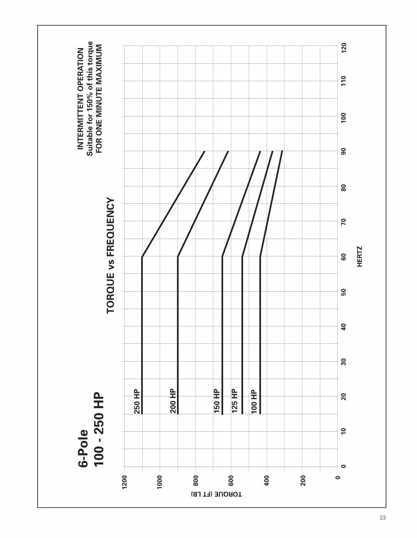
23
010
20
30
40
50
60
70
80
100
90
110
120
6-P
ole
10
0 -
25
0 H
P
TORQUE (FT LB)
HE
RT
Z
0
400
600
800
1000
1200
TO
RQ
UE
vs F
RE
QU
EN
CY
12
5 H
P
20
0 H
P
25
0 H
P
10
0 H
P
200
15
0 H
P
INT
ER
MIT
TE
NT
OP
ER
AT
ION
Su
ita
ble
fo
r 1
50
% o
f th
is t
orq
ue
FO
R O
NE
MIN
UT
E M
AX
IMU
M
App Manual in Spreads 1/16/01 9:03 AM Page 29
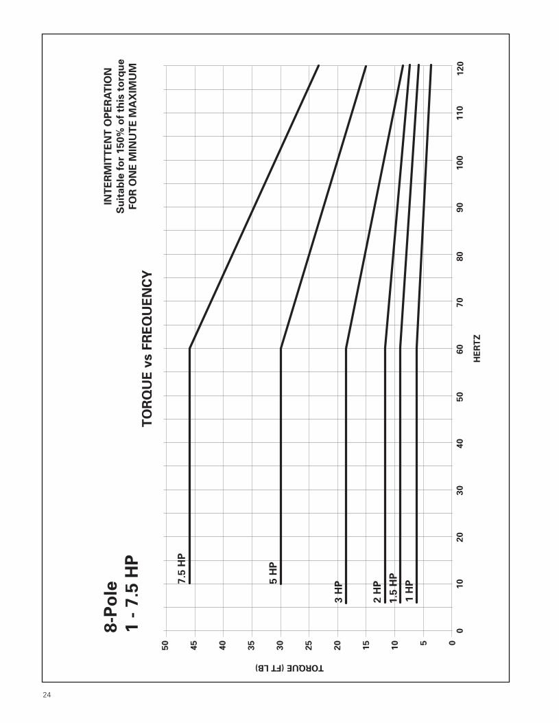
24
010
20
30
40
50
60
70
80
100
90
110
120
8-P
ole
1 -
7.5
HP
TORQUE (FT LB)
HE
RT
Z
05
20
30
40
50
TO
RQ
UE
vs F
RE
QU
EN
CY
7.5
HP
45
10
5 H
P
15
25
35
INT
ER
MIT
TE
NT
OP
ER
AT
ION
Su
ita
ble
fo
r 1
50
% o
f th
is t
orq
ue
FO
R O
NE
MIN
UT
E M
AX
IMU
M
3 H
P
2 H
P
1.5
HP
1 H
P
App Manual in Spreads 1/16/01 9:03 AM Page 26

25
8-P
ole
10
-25
HP
TORQUE (FT LB)
HE
RT
Z
0
20
80
120
160
TO
RQ
UE
vs F
RE
QU
EN
CY
40
15
HP
60
100
140
010
20
30
40
50
60
70
80
100
90
110
120
10
HP2
0 H
P
25
HP
INT
ER
MIT
TE
NT
OP
ER
AT
ION
Su
ita
ble
fo
r 1
50
% o
f th
is t
orq
ue
FO
R O
NE
MIN
UT
E M
AX
IMU
M
App Manual in Spreads 1/16/01 9:03 AM Page 25

26
8-P
ole
30
-1
00
HP
TORQUE (FT LB)
HE
RT
Z
010
20
30
40
50
60
70
80
90
0
100
200
300
400
500
700
TO
RQ
UE
vs F
RE
QU
EN
CY
50
HP
60
HP
75
HP
40
HP
10
0 H
P600
INT
ER
MIT
TE
NT
OP
ER
AT
ION
Su
ita
ble
fo
r 1
50
% o
f th
is t
orq
ue
FO
R O
NE
MIN
UT
E M
AX
IMU
M
30
HP
App Manual in Spreads 1/16/01 9:03 AM Page 22

27
8-P
ole
12
5-2
50
HP
TORQUE (FT LB)
HE
RT
Z
0
200
800
1200
1600
TO
RQ
UE
vs F
RE
QU
EN
CY
400
15
0 H
P
600
1000
1400
010
20
30
40
50
60
70
80
90
12
5 H
P
20
0 H
P
25
0 H
P
INT
ER
MIT
TE
NT
OP
ER
AT
ION
Su
ita
ble
fo
r 1
50
% o
f th
is t
orq
ue
FO
R O
NE
MIN
UT
E M
AX
IMU
M
App Manual in Spreads 1/16/01 9:03 AM Page 21

28
Cons
t.M
ax.
Ohm
s/Ph
(Y e
quiv
.) C
ircu
it Pa
ram
eter
s-25
deg
rees
CTo
rque
Torq
ueH
p @
Min
.Sp
eed
FLF.L
. Am
psN
L A
mps
Nom
.F.L
.Co
nst.
Max
. RPM
Cons
t. H
PRP
MFr
ame
Rang
eRP
M@
460
@ 4
60V
F.L. E
ff.To
rque
HP
Cons
t. H
PTo
rque
X1X2
XMR1
R218
0014
3T10
:117
451.
51.
182
.53.
01.
534
900.
071
7.33
8.02
306
9.45
5.85
112
0014
5T10
:111
401.
81.
380
.04.
62.
322
800.
053
7.47
6.54
214
12.5
08.
6890
018
2T10
:186
01.
91.
278
.56.
13.
117
600.
030
12.2
817
.15
297
15.6
812
.28
3600
143T
10:1
3485
2.0
0.9
82.5
2.3
1.2
5225
0.11
06.
873.
1837
26.
404.
52
1.5
1800
145T
10:1
1740
2.2
1.4
84.0
4.5
2.3
3480
0.10
34.
945.
2719
96.
984.
3712
0018
2T10
:111
602.
31.
585
.56.
83.
423
200.
104
5.22
9.40
185
6.28
4.54
900
184T
10:1
860
2.6
1.8
80.0
9.2
4.6
1760
0.09
8.31
12.0
220
28.
3112
.08
3600
145T
10:1
3495
2.5
1.1
84.0
3.0
1.5
5240
0.14
64.
872.
4528
64.
593.
56
218
0014
5T10
:117
352.
91.
984
.06.
13.
034
700.
146
3.80
4.16
165
5.05
3.56
1200
184T
10:1
1160
3.0
1.9
86.5
9.1
4.5
2320
0.13
93.
597.
3714
54.
263.
4390
021
3T10
:186
53.
32.
282
.512
.06.
017
650.
137.
536.
7414
77.
465.
1336
0018
2T10
:135
103.
61.
786
.54.
52.
352
650.
231
4.34
2.21
193
2.84
2.02
318
0018
2T10
:117
403.
91.
887
.59.
14.
534
800.
208
2.98
4.54
146
3.13
2.62
1200
213T
10:1
1165
4.0
2.3
87.5
14.0
6.8
2330
0.23
03.
244.
5713
03.
251.
7390
021
5T10
:186
54.
73.
184
.018
.09.
017
650.
195.
665.
287
118
5.23
3.87
3600
184T
10:1
3490
5.8
1.8
87.5
7.5
3.8
5235
0.36
02.
621.
5413
51.
861.
40
518
0018
4T10
:117
306.
53.
287
.515
7.6
3460
0.31
01.
712.
7084
.21.
851.
6412
0021
5T10
:111
606.
83.
388
.523
11.3
2320
0.34
02.
012.
9186
.81.
991.
2390
025
4T6:
186
57.
54.
186
.530
15.0
1765
0.66
4.09
4.80
68.4
1.46
1.99
3600
213T
10:1
3515
8.8
3.4
88.5
117.
552
700.
590
2.08
1.46
83.6
1.20
0.71
7.5
1800
213T
10:1
1750
9.5
4.2
89.5
2311
.335
000.
560
1.27
2.48
63.2
1.03
0.75
1200
254T
6:1
1170
9.8
4.5
90.2
3416
.823
401.
090
1.66
1.89
54.3
0.82
0.58
900
256T
6:1
865
126.
687
.546
23.0
1765
1.0
3.00
3.69
56.1
0.91
1.47
3600
215T
10:1
3505
124.
089
.515
10.0
5255
0.76
01.
671.
2774
.00.
970.
60
1018
0021
5T10
:117
5013
5.4
89.5
3015
.035
000.
740
0.99
1.98
49.6
0.82
0.61
1200
256T
6:1
1165
1310
.090
.245
22.5
2330
1.42
1.41
1.71
52.1
0.68
0.53
900
284T
6:1
875
159.
191
.060
36.0
1475
1.4
2.02
2.44
34.6
0.65
0.49
3600
254T
6:1
3530
175.
090
.222
15.0
5295
2.25
1.33
1.03
57.6
0.39
00.
310
1518
0025
4T6:
117
6019
7.3
91.7
4522
.435
202.
20.
851.
6138
.50.
380
0.34
012
0028
4T6:
111
7520
1091
.067
40.0
1955
2.2
1.00
1.11
26.3
0.40
00.
240
900
286T
6:1
875
2314
91.0
9054
.014
752.
11.
341.
6823
.80.
380
0.33
036
0025
6T6:
135
2523
7.4
90.2
3019
.952
853.
00.
950.
8040
.30.
300
0.27
0
2018
0025
6T6:
117
5526
9.1
91.7
6029
.935
102.
90.
601.
2630
.70.
260
0.26
012
0028
6T6:
111
7526
1291
.789
54.0
1955
3.0
0.77
0.93
22.9
0.29
00.
210
900
324T
4:1
860
3118
91.0
119
71.0
1480
4.6
1.15
1.68
14.8
0.23
0.19
336
0028
4TS
6:1
3525
298
91.7
3724
.947
003.
70.
551.
1438
.50.
270
0.21
0
2518
0028
4T6:
117
6529
1393
.074
49.7
2940
3.8
0.55
0.88
22.8
0.19
00.
180
1200
324T
4:1
1180
3315
92.4
111
67.0
1965
5.9
0.67
0.65
16.1
0.17
00.
150
900
326T
4:1
880
3822
90.2
149
89.0
1480
7.0
0.95
1.41
12.6
0.17
40.
159
3600
286T
S6:
135
2534
1091
.745
29.8
4700
4.5
0.42
0.98
33.8
0.20
00.
170
3018
0028
6T6:
117
6535
1593
.089
59.6
2940
4.5
0.44
0.75
20.3
0.15
00.
150
1200
326T
4:1
1180
3919
92.4
134
80.0
1965
7.1
0.56
0.56
13.9
0.15
00.
130
900
364T
4:1
885
4726
91.0
178
119.
013
357.
10.
771.
159.
650.
144
0.08
3
Type
RGZ
ESDI
Inve
rter D
uty,
Thre
e Ph
ase
Vari
ab
le T
orq
ue Z
ero
to
Base S
peed
/ C
on
sta
nt
To
rqu
e P
rem
ium
Eff
icie
ncy
App Manual in Spreads 1/16/01 9:03 AM Page 18
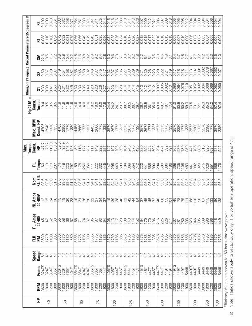
29
Eff
icie
ncy
Valu
es a
re s
how
n fo
r 60
her
tz s
ine
wav
e po
wer
.
Not
e:
Rat
ios
show
n ap
ply
to v
ecto
r du
ty o
nly.
Fo
r vo
lts/h
ertz
ope
ratio
n, s
peed
ran
ge is
4:1
.
Max
.O
hms/
Ph (Y
equ
iv.)
Cir
cuit
Para
met
ers-
25 d
egre
es C
Torq
ueH
p @
Min
.Sp
eed
FLR
F.L. A
mps
NL
Am
psN
om.
F.L.
Cons
t.M
ax. R
PMCo
nst.
HP
RPM
Fram
eRa
nge
PM@
460
@ 4
60V
F.L. E
ff.To
rque
HP
Cons
t. H
PTo
rque
X1X2
XMR1
R236
0032
4TS
6:1
3530
4512
93.6
6047
.747
059.
40.
330.
6022
.60.
088
0.10
0
4018
0032
4T4:
117
7047
1593
.611
979
.229
409.
50.
380.
6718
.50.
110
0.10
012
0036
4T4:
111
8052
2493
.617
811
9.0
1770
9.5
0.41
0.70
11.6
0.10
00.
070
900
365T
4:1
885
6336
91.7
237
158.
013
359.
50.
560.
877.
20.
094
0.06
136
0032
6TS
4:1
3530
5515
93.6
7459
.647
0511
.80.
250.
4918
.80.
072
0.08
3
5018
0032
6T4:
117
7058
1893
.614
898
.929
5011
.90.
310.
5415
.80.
082
0.08
212
0036
5T4:
111
8066
3093
.622
314
8.0
1770
11.9
0.32
0.58
10.4
0.08
10.
058
900
404T
4:1
880
6728
91.7
297
198
1330
11.6
0.49
0.82
10.2
0.07
90.
071
3600
364T
S4:
135
6568
1993
.689
8944
5514
.60.
300.
5614
.80.
066
0.05
4
6018
0036
4T4:
117
7571
2193
.617
811
826
6014
.40.
300.
4611
.60.
066
0.05
112
0040
4T4:
111
8574
2694
.126
617
717
7514
.00.
350.
5810
.80.
049
0.03
390
040
4T4:
188
067
2891
.735
623
713
3011
.60.
490.
8210
.20.
079
0.07
136
0036
5TS
4:1
3565
8522
94.1
111
111
4455
18.2
0.20
0.46
12.8
0.04
50.
041
7518
0036
5T4:
117
7587
2794
.122
214
826
6018
.00.
230.
379.
20.
051
0.04
112
0040
5T4:
111
8593
3494
.533
222
217
7518
.00.
260.
458.
40.
035
0.02
590
044
4T4:
188
594
3793
.044
529
713
3517
.80.
270.
477.
80.
050
0.04
436
0040
5TS
4:1
3570
108
1994
.114
714
735
7024
.40.
210.
3216
.00.
034
0.01
5
100
1800
405T
4:1
1780
113
3094
.529
519
726
7024
.20.
200.
379.
60.
028
0.01
612
0044
4T4:
111
8511
738
94.5
443
296
1775
24.1
0.17
0.35
7.3
0.02
60.
016
900
445T
4:1
885
123
4894
.159
339
513
3523
.70.
200.
366.
10.
034
0.03
336
0044
4TS
4:1
3575
138
3294
.518
418
435
7530
.70.
140.
278.
80.
018
0.01
0
125
1800
444T
4:1
1785
143
4295
.036
824
526
7530
.50.
140.
336.
70.
017
0.01
112
0044
5T4:
111
8514
444
94.5
554
370
1775
30.1
0.14
0.29
6.2
0.02
00.
013
900
447T
4:1
885
152
5493
.674
249
513
3529
.70.
150.
294.
80.
027
0.02
636
0044
5TS
4:1
3575
164
3795
.022
022
035
7536
.70.
100.
217.
20.
012
0.00
7
150
1800
445T
4:1
1785
170
4595
.844
129
426
7536
.50.
120.
306.
10.
015
0.00
912
0044
7T4:
111
8517
045
95.0
665
444
1775
36.1
0.13
0.28
6.1
0.01
70.
012
900
445T
4:1
885
186
7294
.189
059
313
3535
.60.
120.
233.
50.
022
0.02
136
0044
7TS
4:1
3575
216
4095
.029
429
435
7549
.00.
087
0.20
7.0
0.01
00.
006
200
1800
447T
4:1
1785
225
6095
.858
847
123
7548
.70.
085
0.22
4.6
0.01
00.
007
1200
449T
4:1
1185
226
5595
.088
659
217
7548
.10.
092
0.21
4.8
0.01
30.
009
900
449T
4:1
885
241
101
94.5
1186
791
1335
47.4
0.10
0.19
3.1
0.01
80.
018
3600
449T
S4:
135
7026
745
95.4
368
368
3570
61.0
0.69
00.
176.
40.
008
0.00
525
018
0044
9T4:
117
8528
178
95.8
735
589
2380
60.9
0.06
40.
183.
70.
007
0.00
512
0044
9T4:
111
8528
075
95.0
1108
739
1775
60.2
0.07
60.
183.
80.
010
0.00
890
0S
449
4:1
885
303
111
94.5
1483
989
1335
59.3
0.11
00.
112.
70.
009
0.01
236
0044
9TS
4:1
3575
323
6895
.844
144
135
7573
.50.
051
0.13
4.1
0.00
60.
004
300
1800
449T
4:1
1785
346
110
95.4
882
706
2380
73.1
0.05
20.
141
2.7
0.00
70.
004
1200
S44
94:
111
8533
590
95.0
1329
886
1775
72.1
0.09
20.
091
3.2
0.00
70.
008
3600
S44
94:
135
7036
967
95.4
515
515
3570
85.3
0.06
40.
062
4.2
0.00
50.
004
350
1800
S44
94:
117
8539
011
595
.810
2982
523
8085
.30.
066
0.07
92.
40.
004
0.00
412
00S
449
4:1
1185
396
133
95.0
1551
1034
1775
84.2
0.06
90.
067
2.3
0.00
50.
006
400
3600
S44
94:
135
7041
880
95.4
588
588
3570
97.4
0.05
20.
052
3.5
0.00
40.
004
1800
S44
94:
117
8544
913
895
.811
7694
223
8097
.40.
060
0.07
12.
00.
003
0.00
4
App Manual in Spreads 1/16/01 9:03 AM Page 17
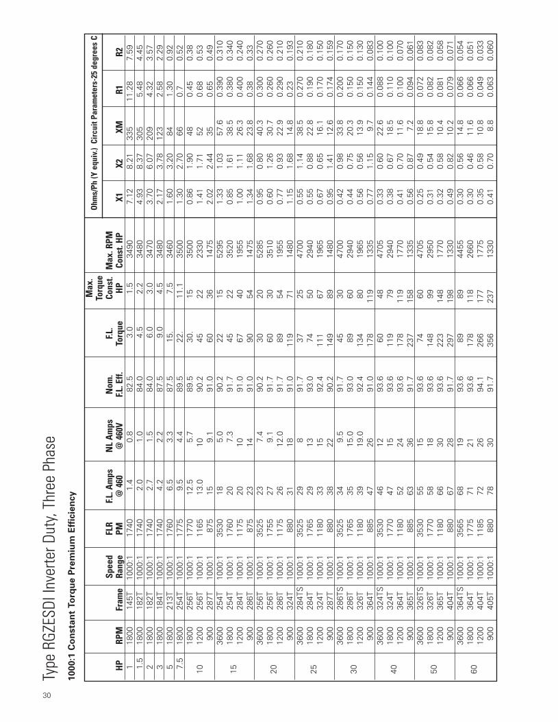
30
Type
RGZ
ESDI
Inve
rter D
uty,
Thre
e Ph
ase
1000:1
Co
nsta
nt
To
rqu
e P
rem
ium
Eff
icie
ncy
Max
.O
hms/
Ph (Y
equ
iv.)
Cir
cuit
Para
met
ers-
25 d
egre
es C
Torq
ueSp
eed
FLR
F.L. A
mps
NL
Am
psN
om.
F.L.
Cons
t.M
ax. R
PMH
PRP
MFr
ame
Rang
ePM
@ 4
60@
460
VF.L
. Eff.
Torq
ueH
PCo
nst.
HP
X1X2
XMR1
R21
1800
145T
1000
:117
401.
40.
882
.53.
01.
534
907.
128.
2133
511
.28
7.59
1.5
1800
182T
1000
:117
402.
01.
084
.04.
52.
234
804.
938.
3730
55.
484.
452
1800
182T
1000
:117
402.
71.
584
.06.
03.
034
703.
706.
0720
94.
323.
573
1800
184T
1000
:117
404.
22.
287
.59.
04.
534
802.
173.
7812
32.
582.
295
1800
213T
1000
:117
606.
53.
387
.515
.7.
534
601.
603.
2084
1.30
0.92
7.5
1800
254T
1000
:117
759.
54.
489
.522
.11
.135
001.
302.
7066
0.7
0.52
1800
256T
1000
:117
7012
.55.
789
.530
.15
3500
0.86
1.90
480.
450.
3810
1200
256T
1000
:111
6513
.010
90.2
4522
2330
1.41
1.71
520.
680.
5390
028
7T10
00:1
875
159.
191
.060
3614
752.
022.
4435
0.65
0.49
3600
254T
1000
:135
3018
5.0
90.2
2215
5295
1.33
1.03
57.6
0.39
00.
310
1518
0025
4T10
00:1
1760
207.
391
.745
2235
200.
851.
6138
.50.
380
0.34
012
0028
4T10
00:1
1175
2010
91.0
6740
1955
1.00
1.11
26.3
0.40
00.
240
900
286T
1000
:187
523
1491
.090
5414
751.
341.
6823
.80.
380.
3336
0025
6T10
00:1
3525
237.
490
.230
2052
850.
950.
8040
.30.
300
0.27
0
2018
0025
6T10
00:1
1755
279.
191
.760
3035
100.
601.
2630
.70.
260
0.26
012
0028
6T10
00:1
1175
2612
.091
.789
5419
550.
770.
9322
.90.
290
0.21
090
032
4T10
00:1
880
3118
91.0
119
7114
801.
151.
6814
.80.
230.
193
3600
284T
S10
00:1
3525
298
91.7
3725
4700
0.55
1.14
38.5
0.27
00.
210
2518
0028
4T10
00:1
1765
2913
93.0
7450
2940
0.55
0.88
22.8
0.19
00.
180
1200
324T
1000
:111
8033
1592
.411
167
1965
0.67
0.65
16.1
0.17
00.
150
900
287T
1000
:188
038
2290
.214
989
1480
0.95
1.41
12.6
0.17
40.
159
3600
286T
S10
00:1
3525
349.
591
.745
3047
000.
420.
9833
.80.
200
0.17
0
3018
0028
6T10
00:1
1765
3515
.093
.089
6029
400.
440.
7520
.30.
150
0.15
012
0032
6T10
00:1
1180
3919
.092
.413
480
1965
0.56
0.56
13.9
0.15
00.
130
900
364T
1000
:188
547
2691
.017
811
913
350.
771.
159.
70.
144
0.08
336
0032
4TS
1000
:135
3046
1293
.660
4847
050.
330.
6022
.60.
088
0.10
0
4018
0032
4T10
00:1
1770
4715
93.6
119
7929
400.
380.
6718
.50.
110
0.10
012
0036
4T10
00:1
1180
5224
93.6
178
119
1770
0.41
0.70
11.6
0.10
00.
070
900
365T
1000
:188
563
3691
.723
715
813
350.
560.
877.
20.
094
0.06
136
0032
6TS
1000
:135
3055
1593
.674
6047
050.
250.
4918
.80.
072
0.08
3
5018
0032
6T10
00:1
1770
5818
93.6
148
9929
500.
310.
5415
.80.
082
0.08
212
0036
5T10
00:1
1180
6630
93.6
223
148
1770
0.32
0.58
10.4
0.08
10.
058
900
404T
1000
:188
067
2891
.729
719
813
300.
490.
8210
.20.
079
0.07
136
0036
4TS
1000
:135
6568
1993
.689
8944
550.
300.
5614
.80.
066
0.05
4
6018
0036
4T10
00:1
1775
7121
93.6
178
118
2660
0.30
0.46
11.6
0.06
60.
051
1200
404T
1000
:111
8572
2694
.126
617
717
750.
350.
5810
.80.
049
0.03
390
040
5T10
00:1
880
7830
91.7
356
237
1330
0.41
0.70
8.8
0.06
30.
060
App Manual in Spreads 1/16/01 9:03 AM Page 14

Eff
icie
ncy
Valu
es a
re s
how
n fo
r 60
her
tz s
ine
wav
e po
wer
.
Not
e:
Rat
ios
show
n ap
ply
to v
ecto
r du
ty o
nly.
Fo
r vo
lts/h
ertz
ope
ratio
n, s
peed
ran
ge is
4:1
.
31
Max
.O
hms/
Ph (Y
equ
iv.)
Cir
cuit
Para
met
ers-
25 d
egre
es C
Torq
ueSp
eed
FLR
F.L. A
mps
NL
Am
psN
om.
F.L.
Cons
t.M
ax. R
PMH
PRP
MFr
ame
Rang
ePM
@ 4
60@
460
VF.L
. Eff.
Torq
ueH
PCo
nst.
HP
X1X2
XMR1
R236
0036
5TS
1000
:135
6585
2294
.111
111
144
550.
200.
4612
.80.
045
0.04
1
7518
0036
5T10
00:1
1775
8727
94.1
222
148.
2660
0.23
0.37
9.2
0.05
10.
041
1200
405T
1000
:111
8587
3494
.533
222
217
750.
260.
458.
40.
035
0.02
590
044
4T10
00:1
885
9437
93.0
445
297
1335
0.27
0.47
7.5
0.05
00.
044
3600
405T
S10
00:1
3570
110
1994
.114
714
735
700.
210.
3216
0.03
40.
015
100
1800
405T
1000
:117
8011
330
94.5
295
197
2670
0.20
0.37
9.6
0.02
80.
016
1200
444T
1000
:111
8511
538
94.5
443
296
1775
0.17
0.35
7.3
0.02
60.
016
900
445T
1000
:188
512
348
94.1
593
395
1335
0.20
0.36
6.1
0.03
40.
033
3600
444T
S10
00:1
3575
136
3294
.518
418
435
750.
140.
278.
80.
018
0.01
012
518
0044
4T10
00:1
1785
143
4295
.036
824
526
750.
140.
336.
70.
017
0.01
112
0044
5T10
00:1
1185
144
4494
.555
437
017
750.
140.
296.
20.
020
0.01
390
044
7T10
00:1
885
152
5493
.674
249
513
350.
150.
294.
80.
027
0.02
636
0044
5TS
1000
:135
7516
037
95.0
220
220
3575
0.10
0.21
7.2
0.01
20.
007
150
1800
445T
1000
:117
8516
945
95.8
441
294
2675
0.12
0.30
6.1
0.01
50.
009
1200
447T
1000
:111
8516
945
95.0
665
444
1775
0.13
0.28
6.1
0.01
70.
012
900
447T
1000
:188
518
672
94.1
890
593
1335
0.12
0.23
3.5
0.02
20.
021
3600
447T
S10
00:1
3575
208
4095
.029
429
435
750.
087
0.20
7.0
0.01
00.
006
200
1800
447T
1000
:117
8522
360
95.8
588
421
2375
0.08
50.
224.
60.
010
0.00
712
0044
9T10
00:1
1185
222
5595
.088
659
217
750.
092
0.21
4.8
0.01
30.
009
900
449T
1000
:188
524
110
194
.511
8691
1335
0.10
0.19
3.1
0.01
80.
018
3600
449T
S10
00:1
3570
264
4595
.436
836
835
700.
690
0.17
6.4
0.00
80.
005
250
1800
449T
1000
:117
8528
278
95.8
735
589
2380
0.06
40.
183.
70.
007
0.00
512
0044
9T10
00:1
1185
285
7595
.011
0873
917
750.
076
0.18
3.8
0.01
00.
008
900
S44
910
00:1
885
303
111
94.5
1483
989
1335
0.11
0.11
2.7
0.00
90.
012
3600
449T
S10
00:1
3575
330
6895
.844
144
135
750.
051
0.13
4.1
0.00
60.
004
300
1800
449T
1000
:117
8534
511
095
.488
270
623
800.
052
0.14
12.
70.
007
0.00
412
00S
449
1000
:111
8533
590
95.0
1329
886
1775
0.09
20.
091
3.2
0.00
70.
008
3600
S44
910
00:1
3570
370
6795
.451
551
535
700.
064
0.06
24.
20.
005
0.00
435
018
00S
449
1000
:117
8539
011
595
.810
2982
523
800.
066
0.07
92.
40.
004
0.00
412
00S
449
1000
:111
8539
613
395
.015
5110
3417
750.
069
0.06
72.
30.
005
0.00
6
400
3600
S44
910
00:1
3570
420
8095
.458
858
835
700.
052
0.05
23.
50.
004
0.00
418
00S
449
1000
:117
8545
013
895
.811
7694
223
800.
060
0.07
12.
00.
003
0.00
4
App Manual in Spreads 1/16/01 9:03 AM Page 13
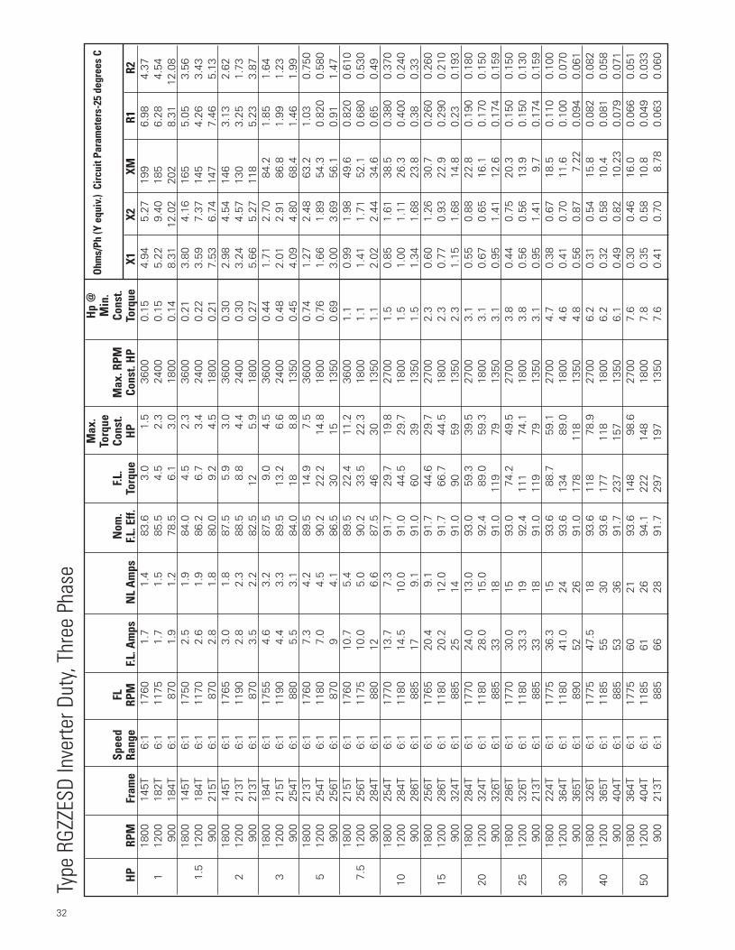
32
Max
.H
p @
Ohm
s/Ph
(Y e
quiv
.) C
ircui
t Par
amet
ers-
25 d
egre
es C
Torq
ueM
in.
Spee
dFL
Nom
.F.L
.Co
nst.
Max
. RPM
Cons
t. H
PRP
MFr
ame
Rang
eRP
MF.L
. Am
psN
L A
mps
F.L. E
ff.To
rque
HP
Cons
t. H
PTo
rque
X1X2
XMR1
R218
0014
5T6:
117
601.
71.
483
.63.
01.
536
000.
154.
945.
2719
96.
984.
371
1200
182T
6:1
1175
1.7
1.5
85.5
4.5
2.3
2400
0.15
5.22
9.40
185
6.28
4.54
900
184T
6:1
870
1.9
1.2
78.5
6.1
3.0
1800
0.14
8.31
12.0
220
28.
3112
.08
1800
145T
6:1
1750
2.5
1.9
84.0
4.5
2.3
3600
0.21
3.80
4.16
165
5.05
3.56
1.5
1200
184T
6:1
1170
2.6
1.9
86.2
6.7
3.4
2400
0.22
3.59
7.37
145
4.26
3.43
900
215T
6:1
870
2.8
1.8
80.0
9.2
4.5
1800
0.21
7.53
6.74
147
7.46
5.13
1800
145T
6:1
1765
3.0
1.8
87.5
5.9
3.0
3600
0.30
2.98
4.54
146
3.13
2.62
212
0021
3T6:
111
902.
82.
388
.58.
84.
424
000.
303.
244.
5713
03.
251.
7390
021
3T6:
187
03.
52.
282
.512
5.9
1800
0.27
5.66
5.27
118
5.23
3.87
1800
184T
6:1
1755
4.6
3.2
87.5
9.0
4.5
3600
0.44
1.71
2.70
84.2
1.85
1.64
312
0021
5T6:
111
904.
43.
389
.513
.26.
624
000.
482.
012.
9186
.81.
991.
2390
025
4T6:
188
05.
53.
184
.018
8.8
1350
0.45
4.09
4.80
68.4
1.46
1.99
1800
213T
6:1
1760
7.3
4.2
89.5
14.9
7.5
3600
0.74
1.27
2.48
63.2
1.03
0.75
05
1200
254T
6:1
1180
7.0
4.5
90.2
22.2
14.8
1800
0.76
1.66
1.89
54.3
0.82
00.
580
900
256T
6:1
870
94.
186
.530
1513
500.
693.
003.
6956
.10.
911.
4718
0021
5T6:
117
6010
.75.
489
.522
.411
.236
001.
10.
991.
9849
.60.
820
0.61
07.
512
0025
6T6:
111
7510
.05.
090
.233
.522
.318
001.
11.
411.
7152
.10.
680
0.53
090
028
4T6:
188
012
6.6
87.5
4630
1350
1.1
2.02
2.44
34.6
0.65
0.49
1800
254T
6:1
1770
13.7
7.3
91.7
29.7
19.8
2700
1.5
0.85
1.61
38.5
0.38
00.
370
1012
0028
4T6:
111
8014
.510
.091
.044
.529
.718
001.
51.
001.
1126
.30.
400
0.24
090
028
6T6:
188
517
9.1
91.0
6039
1350
1.5
1.34
1.68
23.8
0.38
0.33
1800
256T
6:1
1765
20.4
9.1
91.7
44.6
29.7
2700
2.3
0.60
1.26
30.7
0.26
00.
260
1512
0028
6T6:
111
8020
.212
.091
.766
.744
.518
002.
30.
770.
9322
.90.
290
0.21
090
032
4T6:
188
525
1491
.090
5913
502.
31.
151.
6814
.80.
230.
193
1800
284T
6:1
1770
24.0
13.0
93.0
59.3
39.5
2700
3.1
0.55
0.88
22.8
0.19
00.
180
2012
0032
4T6:
111
8028
.015
.092
.489
.059
.318
003.
10.
670.
6516
.10.
170
0.15
090
032
6T6:
188
533
1891
.011
979
1350
3.1
0.95
1.41
12.6
0.17
40.
159
1800
286T
6:1
1770
30.0
1593
.074
.249
.527
003.
80.
440.
7520
.30.
150
0.15
025
1200
326T
6:1
1180
33.3
1992
.411
174
.118
003.
80.
560.
5613
.90.
150
0.13
090
021
3T6:
188
533
1891
.011
979
1350
3.1
0.95
1.41
9.7
0.17
40.
159
1800
224T
6:1
1775
36.3
1593
.688
.759
.127
004.
70.
380.
6718
.50.
110
0.10
030
1200
364T
6:1
1180
41.0
2493
.613
489
.018
004.
60.
410.
7011
.60.
100
0.07
090
036
5T6:
189
052
2691
.017
811
813
504.
80.
560.
877.
220.
094
0.06
118
0032
6T6:
117
7547
.518
93.6
118
78.9
2700
6.2
0.31
0.54
15.8
0.08
20.
082
4012
0036
5T6:
111
8555
3093
.617
711
818
006.
20.
320.
5810
.40.
081
0.05
890
040
4T6:
188
553
3691
.723
715
713
506.
10.
490.
8210
.23
0.07
90.
071
1800
364T
6:1
1775
6021
93.6
148
98.6
2700
7.6
0.30
0.46
16.0
0.06
60.
051
5012
0040
4T6:
111
8561
2694
.122
214
818
007.
80.
350.
5810
.80.
049
0.03
390
021
3T6:
188
566
2891
.729
719
713
507.
60.
410.
708.
780.
063
0.06
0
Type
RGZ
ZESD
Inve
rter D
uty,
Thre
e Ph
ase
App Manual in Spreads 1/16/01 9:03 AM Page 10

33
Notes
• Pounds x 4.448 = NewtonsNewtons X .2248 = Pounds
• HP x .746 = KWKW x 1.341 = HP
• Torque (Lb. = Ft.) = HP X 5250RPM
• Torque (Newton - meters):Nm x .7376 - Lb. - Ft.(Lb. Ft. x 1.356 = Nm)
• HP = Torque (Lb. - Ft.) x RPM5250
• WK2 (Inertia - Lb. Ft.2) at motor Shaft = (Load RPM ÷ Mtr. F.L. RPM)2 x Load WK2
• Inertia (Kilogram - meter2):kgm2 x 23.73 = Lb. Ft.2
(Lb. Ft.2 ÷ 23.73 = kgm2)(Lb. Ft.2 ÷ .042 = kgm2)
• Power (Kilowatts):Kw x 1.341 = HP(HP ÷ 1.341 = Kw)(HP x .746 = Kw)
• Temperature:°C = 5/9 (°F - 32)°F = (9/5 x °C) + 32
• Performance Data Notes:
To find amperes at various voltages:575 V Data = 460 V Amperes x .80230 V Data = 460 V Amperes x 2.0200 V Data = 460 V Amperes x 2.3
(Amperes = Full Load, Locked Rotorand No Load Values - from data pages)
All other data (KVA Code, Efficiencies, Power Factors,Torques and Stall Times) remain same as 460 V Data(winding connections can change - rarely - with volt-age designs).
Max
.H
p @
Ohm
s/Ph
(Y e
quiv
.) C
ircui
t Par
amet
ers-
25 d
egre
es C
Torq
ueM
in.
Spee
dFL
Nom
.F.L
.Co
nst.
Max
. RPM
Cons
t. H
PRP
MFr
ame
Rang
eRP
MF.L
. Am
psN
L A
mps
F.L. E
ff.To
rque
HP
Cons
t. H
PTo
rque
X1X2
XMR1
R218
0036
5T6:
117
7571
2794
.117
711
827
009.
30.
230.
379.
20.
052
0.04
160
1200
405T
6:1
1190
7434
94.5
265
176
1800
9.6
0.26
0.45
8.4
0.03
50.
025
900
444T
6:1
890
7730
91.7
356
235
1350
9.5
0.27
0.47
7.81
0.05
00.
044
1800
405T
6:1
1780
8630
94.5
221
147
2700
11.8
0.20
0.37
9.6
0.02
80.
016
7512
0044
4T6:
111
8588
3894
.533
322
218
0011
.70.
170.
357.
30.
026
0.01
690
044
5T6:
189
095
3793
.044
529
413
5011
.90.
200.
366.
070.
034
0.03
318
0044
4T6:
117
8511
842
95.0
294
196
2700
16.0
0.14
0.33
6.7
0.01
70.
011
100
1200
445T
6:1
1185
118
4494
.544
329
518
0015
.60.
140.
296.
20.
020
0.01
390
044
7T6:
189
012
448
94.1
593
392
1350
15.8
0.15
0.29
4.80
0.02
70.
026
1800
445T
6:1
1785
143
4595
.836
824
527
0020
.00.
120.
306.
10.
015
0.00
912
512
0044
7T6:
111
8514
245
95.0
554
369
1800
19.5
0.13
0.28
6.1
0.01
70.
012
900
447T
6:1
890
159
5493
.674
249
013
5019
.80.
120.
233.
510.
022
0.02
118
0044
7T6:
117
8517
160
95.8
441
294
2700
16.0
0.08
50.
224.
60.
010
0.00
715
012
0044
9T6:
111
8517
055
95.0
665
443
1800
23.4
0.09
20.
214.
80.
013
0.00
990
044
9T6:
189
018
672
94.1
890
588
1350
23.7
0.10
0.19
3.08
0.01
80.
018
200
1800
449T
6:1
1785
223
7895
.858
839
227
0031
.90.
064
0.18
3.7
0.00
70.
005
1200
449T
6:1
1185
225
7595
.088
659
118
0031
.20.
076
0.18
3.8
0.01
00.
008
App Manual in Spreads 1/16/01 9:03 AM Page 9
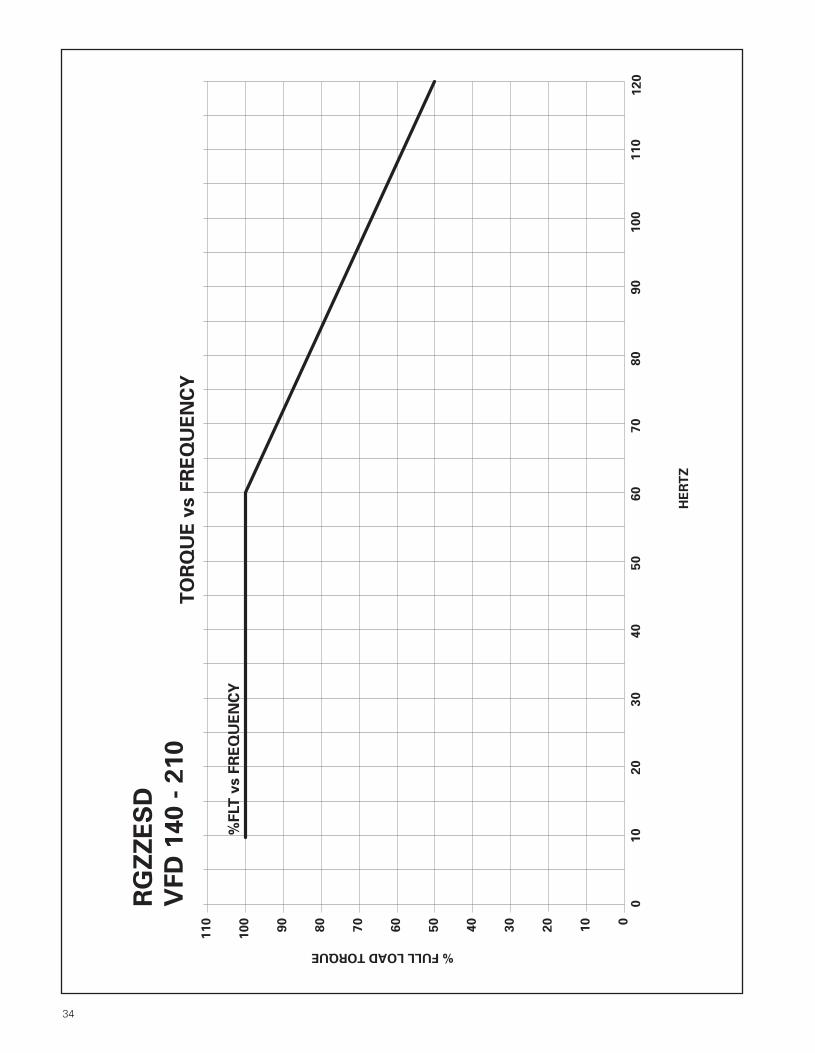
34
010
20
30
40
50
60
70
80
100
90
110
120
RG
ZZ
ES
D
VF
D 1
40
- 2
10
% FULL LOAD TORQUE
HE
RT
Z
0
20
50
70
90
110
TO
RQ
UE
vs F
RE
QU
EN
CY
%F
LT
vs F
RE
QU
EN
CY
100
80
60
30
40
10
App Manual in Spreads 1/16/01 9:03 AM Page 6

35
RG
ZZ
ES
D
VF
D 2
50
-44
9
HE
RT
Z
010
20
30
40
50
60
70
80
90
0
20
40
60
80
100
120
%F
LT
vs F
RE
QU
EN
CYT
OR
QU
E v
s F
RE
QU
EN
CY
% FULL LOAD TORQUE
App Manual in Spreads 1/16/01 9:03 AM Page 5
501.897.4905
Siemens Energy & Automation, Inc. Industrial Products Division14000 Dineen DriveLittle Rock, AR 72206
©2001 Siemens Energy & Automation, Inc.Specifications are subject to change without notice
More Reasons to Make Siemens your Motor of Choice
Superb Quality.In addition to incorporating quality materials,each Siemens motor undergoes more than100 separate quality inspections at the factorybefore it’s good enough to be offered to you.Personal involvement and responsibility helpput the extra reliability in Siemens motors.ISO 9001 certification assures our promise to
you.
OutstandingSupport.We pride ourselves onin-stockavailability.Our servicecenter inLittle Rock,Arkansashas thetechnical
expertise, dedication to customer ser-vice, and modification capabilities tokeep you up and running. Ask oursales engineers to help you translatethe most demanding applicationproblem into specifications — and prompt delivery.
Consistent Line.Specify Siemens withthe confidence thatevery motor, from thesmallest to the largest,offers the same qualityand reliability.
Field Support.Siemens’ authorizedservice centers,distributors and fieldsales offices are readyto respond with theexpertise you require.We also back you withan express orderprocessing system and
fast dispatch of replacement parts.
Global Presence.As a worldwide leader in electricalproducts, Siemens offers consistentsupport and service... virtually any-where in the world. For over 150years, Siemens has been deliveringthe total solution. With more than400 manufacturing sites worldwide,Siemens conducts business in 150countries.
TheCompleteSolution.Complete
solutions rely on com-prehensive product
lines. Siemensmotors are anintegral part of avast array ofindustrial productsincluding variablespeed drives, control and automationproducts, switchgear, motor control centersand power distribution equipment.
NMSA-L10005M 101TI Printed in U.S.A.
RGZESInverte
App Manual in Spreads 1/16/01 9:03 AM Page 2

C
ES
N-W
B2F
BS BAKK
V
Application Manual for NEMA Motors
NMCD-L4000-0897 ©1997 Siemens Energy & Automation, Inc. All Rights ReservedThis document, in part, contains information confidential and proprietary to Siemens Energy & Automation, Inc. (SE&A) and is to be usedsolely for the purpose for which it is furnished and returned to SE&A upon request. This document and the information contained thereinshall not be altered, reproduced, transmitted, or disclosed to any third party or otherwise used without the express written consent of SE&A.All information herein is subject to change without notice.

NEMA Frames Application Manual
Table of Contents
Page DateSection 1 Index of Products
1 Product Range and Scope 1 6/972 Construction Features 1 6/973 Motor Type Designations 1 6/97
Section 2 Basic Motor Terminology and Theory1 Motor Terminology 1-4 6/972 Basic Noise Theory 1-6 6/973 Effect of Power Supply Variations 7 6/97
Section 3 Descriptive Material 1 6/97
Section 4 Dimensional Drawings
Horizontal Motors1 Slide Bases 1-5 6/972 Open Drip-proof 1-14 6/973 Totally Enclosed Fan Cooled 1-31 6/974 Severe Duty 1-39 6/975 Explosion-proof 1-24 6/97
Vertical Motors6 Totally Enclosed Fan Cooled 1-16 6/976 Hollow Shaft 17-19 6/977 Severe Duty 1-27 6/978 Explosion-proof 1-27 6/97
Section 5 Electrical Data1 Frame Assignments 1-5 6/972 Speed Torque Curves 1-91 6/973 Insulation System 1-2 6/974 External Load WK2 Capabilities 1-4 6/975 Connection Diagrams 1-4 6/976 Temperature Rise 1 6/97

Application Manual for NEMA Motors
Table of Contents
Page DateSection 6 Mechanical Data
1 Conduit Boxes 1-3 6/972 Standard Rotor Balance 1-2 6/973 Standard Shaft Material 1 6/974 Motor Bearing Sizes 1-6 6/975 Belted Service 1 6/976 Rotor Weight and WK2 1-5 6/977 Paint Standard 1 6/978 Packaging 1 6/979 Noise Data 6/97
10 Modifications for Low Temperature 1 6/97
Section 7 Accessories1 Space Heaters 1-2 6/972 Thermal Protective Devices 1-2 6/97
Section 8 Standards1 National Electrical Manufactures Association 1-2 6/972 The Institute of Electrical and Electronic Engineers 1-2 6/973 American Petroleum Institute 1 6/974 Hazardous Location Classifications and
Underwriters Laboratory 1-7 6/975 Canadian Standards Association 1-2 6/976 Standards Agencies’ Addresses 1-7 6/977 CE Mark 1-2 6/97
Section 9 Tests1 Standard Commercial Test 1 6/972 Complete Test 1 6/973 Noise Test 1 6/97
Section 10 Special Applications and Information1 Power Factor Correction 1-4 6/972 Methods of Starting 3 Phase Motors 1-14 6/973 Duty Cycles and Inertia 1-7 6/974 Horsepower Determination 1 6/975 General Formulas 1-3 6/97

NEMA Frames Application Manual
Special Applications and Information
SectionPartPageDate
80Index6/97
Page Date
Part 1 National Electrical Manufacturers Association (NEMA) 1 - 2 6/97
Part 2 The Institute of Electrical and Electronic Engineers (IEEE) 1 - 2 6/97
Part 3 American Petroleum Institute (API) 1 6/97
Part 4 Hazardous Location Classifications 1 6/97Underwriters Laboratory Labeling 2 6/97Hazardous Location Chart 3 6/97Substances and Atmospheres Chart 4 6/97Special Construction Features and User Information 5-7 6/97
Part 5 Canadian Standards Association (CSA) 1 - 2 6/97
Part 6 Standards Agencies’ Addresses 1 6/97
Part 7 CE Mark (Declaration of Conformity) 1 - 2 6/97
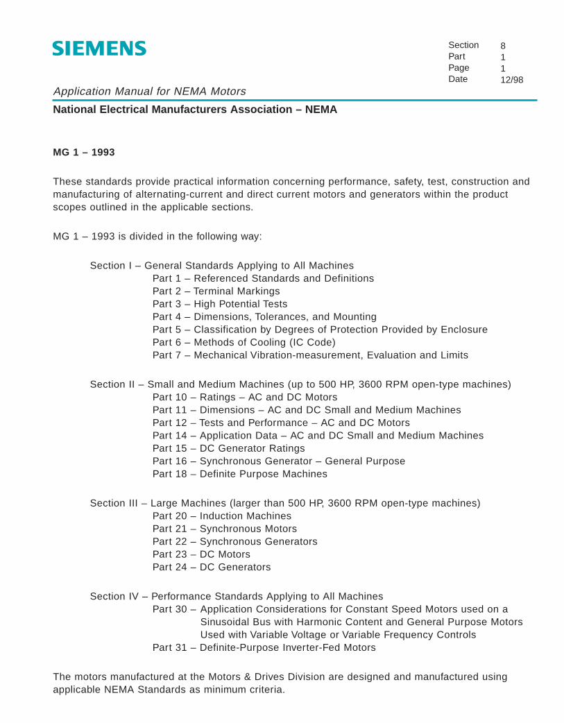
Application Manual for NEMA Motors
National Electrical Manufacturers Association – NEMA
SectionPartPageDate
81112/98
MG 1 – 1993
These standards provide practical information concerning performance, safety, test, construction andmanufacturing of alternating-current and direct current motors and generators within the productscopes outlined in the applicable sections.
MG 1 – 1993 is divided in the following way:
Section I – General Standards Applying to All MachinesPart 1 – Referenced Standards and DefinitionsPart 2 – Terminal MarkingsPart 3 – High Potential TestsPart 4 – Dimensions, Tolerances, and MountingPart 5 – Classification by Degrees of Protection Provided by EnclosurePart 6 – Methods of Cooling (IC Code)Part 7 – Mechanical Vibration-measurement, Evaluation and Limits
Section II – Small and Medium Machines (up to 500 HP, 3600 RPM open-type machines)Part 10 – Ratings – AC and DC MotorsPart 11 – Dimensions – AC and DC Small and Medium MachinesPart 12 – Tests and Performance – AC and DC MotorsPart 14 – Application Data – AC and DC Small and Medium MachinesPart 15 – DC Generator RatingsPart 16 – Synchronous Generator – General PurposePart 18 – Definite Purpose Machines
Section III – Large Machines (larger than 500 HP, 3600 RPM open-type machines)Part 20 – Induction MachinesPart 21 – Synchronous MotorsPart 22 – Synchronous GeneratorsPart 23 – DC MotorsPart 24 – DC Generators
Section IV – Performance Standards Applying to All MachinesPart 30 – Application Considerations for Constant Speed Motors used on a
Sinusoidal Bus with Harmonic Content and General Purpose MotorsUsed with Variable Voltage or Variable Frequency Controls
Part 31 – Definite-Purpose Inverter-Fed Motors
The motors manufactured at the Motors & Drives Division are designed and manufactured usingapplicable NEMA Standards as minimum criteria.

Application Manual for NEMA Motors
National Electrical Manufacturers Association – NEMA
SectionPartPageDate
81212/98
MG 2 - 1989
This standard defines construction requirements of electric machines intended for use in circuits of 50 volts and higher and provides recommendations for their selection, installation, and use in such amanner as to provide for the practical safeguarding of persons and property.
MG 3 - 1974
This standard provides a method of estimating sound levels for installed rotating electrical machines.
MG 10 - 1994
This standard is an energy management guide for selection and use of fixed frequency AC squirrel-cage polyphase induction motors.
MG 13 - 1984This standard covers frame assignments for single phase and polyphase integral HP inductionmotors.

Application Manual for NEMA Motors
The Institute of Electrical and Electronics Engineers - IEEE
SectionPartPageDate
82112/98
The following IEEE Standards may be used in specifying NEMA frame size motors.
IEEE 112 - 1991 Test Procedures for Polyphase induction Motors and Generators
This standard covers instructions for conducting and reporting the moregenerally applicable and acceptable tests to determine the performancecharacteristics of polyphase induction motors and generators.
IEEE 85 - 1973 Test Procedure for Airborne Sound Measurements on Rotating ElectricMachinery
This procedure defines approved methods for conducting tests and reportingresults to effect the uniform determination of rotating electric machine soundunder steady-state conditions with an accuracy of +3dB.
IEEE 45 - 1983 Practice for Electric Installations on Shipboard
These Marine Recommendations are to serve as a guide for the equipment ofmerchant vessels with an electric plant system and electric apparatus forlighting, signaling, communication, power and propulsion. They indicate what isconsidered good engineering practice with reference to safety of the personneland of the ship itself as well as reliability and durability of the apparatus.
IEEE 117 - 1974 Test Procedure for Evaluation of Systems of Insulating Materials for Random-Wound AC Electric Machinery
This test procedure has been prepared to outline useful methods for theevaluation of systems of insulation for random wound stators of rotating electricmachines. The purpose of this test procedure is to classify insulation systems inaccordance with their temperature limits by test, rather than by chemicalcomposition. The intention is to classify according to the recognized A, B, F andH categories.

Application Manual for NEMA Motors
The Institute of Electrical and Electronics Engineers - IEEE
SectionPartPageDate
82212/98
IEEE 275 - 1992 Test Procedure for Evaluation of Systems of Insulating Materials for AC ElectricMachinery Employing Form-Wound Pre-insulated Stator Coils
This test procedure has been prepared to outline useful methods for theevaluation of systems of insulation for form-wound stators of rotating electricmachines. The purpose is the same as that stated for IEEE-117 above.
IEEE 841 - 1994 IEEE Standard for Chemical Industry Severe Duty TEFC Squirrel Cage InductionMotors Up to and Including 500 HP
The purpose of this standard is to define a specification that deals withmechanical and electrical performance, electrical insulation systems, corrosionprotection, and electrical and mechanical testing for severe duty TEFC squirrelcage polyphase induction motors, up to and including 500 HP, for petroleum andchemical industry application. Many of the specified materials and componentsin this standard stem from experience with severely corrosive atmospheres andthe necessity for safe, quiet, reliable, high-efficiency motors.
IEEE 323
IEEE 334
IEEE 344
These standards relate to Class 1E safety-related equipment for use in nuclearpower generating stations. We do not manufacture motors to these standards.
Application Manual for NEMA Motors
American Petroleum Institute - API
SectionPartPageDate
83112/98
API 541 - April 1995 This standard, together with applicable motor data sheets and jobspecifications, covers the requirements for form-wound squirrel cageinduction motors 250 HP and larger for use in petroleum industry services.
NOTE: This standard is written with the intention of being a guideline forpreparing specifications by a company for a specific job or project. Wecannot build motors to this specification because it requires choices to bemade whether certain paragraphs are applicable for the particular job.
API 610 - 1995 This specification covers centrifugal pumps for general refinery services.
Section 3.1 of the specification is a general guide to motor selection andrequires motors for vertical pumps to have the thrust bearing at the top ofthe motor. The In-Line Vertical Pump Motors manufactured by the Motors & Drives Division do not meet all requirements of this specification.

Application Manual for NEMA Motors
Hazardous Location Classifications
SectionPartPageDate
84112/98
Abstract
In spite of a lot of technical articles written on this subject, the complexities still remain. The mainpurpose of this paper is to simplify the complexities, the classification of these motors, and make iteasier for the user to understand.
Classification
There are three main categories of classification:
1. Division2. Class3. Groups
Division: In real sense, it means location or area of the hazard.There are only two types of divisions.
Division 1 Hazard can occur under normal conditions.Division 2 Hazard can occur only under abnormal conditions.
Local safety authorities decide what are normal and abnormal conditions.Therefore, the first step is to contact local authorities to define the location if it is Division 1 or Division 2.
Class: Defines the type of hazard. There are three different classes.
Class I Consists of chemical gases or vapors in the environment, such as gasoline or acetylene.
Class II Consists of flammable dust in the environment, such as coke dust, grain dust, etc.
Class III Consists of flammable lint or fibers in the area, such as textile, saw dust, etc.
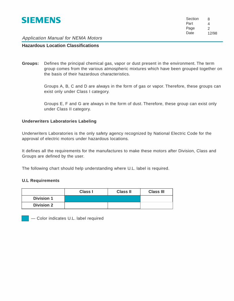
Application Manual for NEMA Motors
Hazardous Location Classifications
SectionPartPageDate
84212/98
Groups: Defines the principal chemical gas, vapor or dust present in the environment. The termgroup comes from the various atmospheric mixtures which have been grouped together onthe basis of their hazardous characteristics.
Groups A, B, C and D are always in the form of gas or vapor. Therefore, these groups canexist only under Class I category.
Groups E, F and G are always in the form of dust. Therefore, these group can exist onlyunder Class II category.
Underwriters Laboratories Labeling
Underwriters Laboratories is the only safety agency recognized by National Electric Code for theapproval of electric motors under hazardous locations.
It defines all the requirements for the manufactures to make these motors after Division, Class andGroups are defined by the user.
The following chart should help understanding where U.L. label is required.
U.L Requirements
— Color indicates U.L. label required
Class II Class III
Division 1
Division 2
Class I
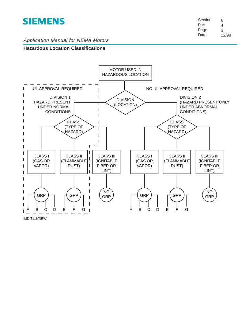
Application Manual for NEMA Motors
Hazardous Location Classifications
SectionPartPageDate
84312/98
MOTOR USED INHAZARDOUS LOCATION
DIVISION(LOCATION)
UL APPROVAL REQUIRED
CLASS(TYPE OFHAZARD)
CLASS I(GAS ORVAPOR)
GRP
A C EB D GF
GRPNO
GRP
CLASS II(FLAMMABLE
DUST)
CLASS III(IGNITABLEFIBER OR
LINT)
DIVISION 1HAZARD PRESENT
UNDER NORMALCONDITIONS
NO UL APPROVAL REQUIRED
CLASS(TYPE OFHAZARD)
CLASS I(GAS ORVAPOR)
GRP
A C EB D GF
GRPNO
GRP
CLASS II(FLAMMABLE
DUST)
CLASS III(IGNITABLEFIBER OR
LINT)
DIVISION 2(HAZARD PRESENT ONLYUNDER ABNORMALCONDITIONS)
IMD-T116(NEW)

Application Manual for NEMA Motors
Substances and Atmospheres Chart
SectionPartPageDate
84412/98
Table I, Class I Substances and AtmospheresSubstance or Atmosphere Minimum Ignition
TemperatureGroup Aacetylene 303 C (581 F)
Group Bbutadiene 420 C (788 F)ethylene oxide 429 C (804 F)
Group Cacetaldehyde 175 C (347 F)cyclopropane 500 C (932F)diethyl ether 160 C (320 F)ethylene 450 C (842 F)isoprene 220 C (428 F)unsymmetrical dimethyl hydrazine 249 C (480 F)(UDMH) 1, 1-dimethyl hydrazine)
Group Dacetone 465 C (869 F)acrylonitrile 481 C (898 F)ammonia 498 C (928 F)benzene 560 C (1040 F)butane 405 C (761 F)1-butane (butyl alcohol) 365 C (689 F)2-butanol (secondary butyl alcohol) 405 C (761 F)n-butyl acetate 425 C (797 F)isobutyl acetate 421 C (790 F)ethane 515 C (959 F)ethanol (ethyl alcohol) 365 C (689 F)ethyl acetate 427 C (800 F)ethylene dichloride 413 C (775 F)gasoline 280 C (536 F)heptanes 215 C (419 F)hexanes 225 C (437 F)methane (natural gas) 540 C (1004 F)methanol (methyl alcohol) 385 C (725 F)3-methyl-1butanol (isoamyl alcohol)350 C (662 F)methyl ethyl ketone 516 C (960 F)methyl isobutyl ketone 460 C (860 F)2-methyl-propanol (isobutyl alcohol)427 C (800 F)2-methyl-2propanol (tertiary butyl alcohol)480 C(896 F)octanes 220 C (428 F)petroleum naptha 288 C (550 F)1-pentanol (amyl alcohol) 300 C (572 F)propane 450 C (842 F)1-propanol (propyl alcohol) 440 C (824 F)2-propanol (isopropyl alcohol) 399 C (750 F)
Minimum IgnitionSubstance or Atmosphere TemperatureGroup Dpropylene 460 C (860 F)
styrene 490 C (914 F)
vinyl acetate 402 C (756 F)
vinyl chloride 472 C (882 F)
xylenes 465 C (869 F)
Table II. Class II Substances(General Definitions — Examples)
Group EMetallic dusts
Dusts of aluminum, magnesium, theircommercial alloys and other metals ofsimilarly hazardous characteristics.
Group FElectrically conducting non-metallic dusts
Coal dust, pulverized coal, pulverized coke,pulverized charcoal, carbon black andsimilar substances.
Group GElectrically non-conducting dusts
Grain dusts, grain product dusts, pulverizedsugar, pulverized starch, dried powderedpotato, pulverized cocoa, pulverized spices,dried egg and milk powder, wood flour,oilmeal from beans and seeds, dried hayand other products producing combustibledust when dried or handled and othersimilar substances.
Table III. Class III Substances.
(No Groups Assigned)Ignitable Fibers or Flyings
Rayon Cotton
Sawdust Sisal
Henequen Istle
Jute Hemp
Tow Cocoa fiber
Oakum Baled waste kapok
Spanish moss Excelsior
(and other materials of similar nature)

Application Manual for NEMA Motors
Special Construction Features
SectionPartPageDate
84512/98
1. Most are provided with thermal protectors.
2. Most are made of cast iron frame.
3. Conduit boxes of the motors going in Division 1 are specially sealed.
4. Class I motors have longer lap joints, tighter fits and longer flame paths so that if an explosiondoes occur in the motor, it’s contained in the motor and flames coming out through the joints arecooled enough to be extinguished. They may be bolted by hardened steel bolts.
5. Motors used in atmosphere of less than -25˚ C require still stronger construction featuresbecause of the extra stresses, also because of the increase in the density of the environment.The amount of energy required to cause an explosion is more but explosion is of much greaterintensity. Standard explosion-proof motors are not useable below -25˚ C without special ULtesting, approval and marking.
6. Class II motors have bearing dust seals.
7. Non-sparking fan made of aluminum, bronze or plastic is used to prevent possible friction sparksin case of any small stones or metal object getting into the air stream and bouncing off fanblades, and to prevent the build-up of static electrical charge which could generate a spark.

Application Manual for NEMA Motors
Special Information for User
SectionPartPageDate
84612/98
U.L. does not offer any standards on Division 1 Class 1 Groups A and B.
U.L. does not offer any standards on Division 2 motors.
U.L. does not offer any standards on Class 3 motors.
U.L. does not offer any standards for motors used below ambients of -25˚ C, but will conductindividual tests at whatever low ambient is desired.
Motors rated at 3/4 HP and less may have internally mounted automatic thermal overload. Cautionshould be observed when applying these to the machinery as automatic thermal overload resets andstarts the motor.
Motors rated at 1 HP and more may have thermostats on the windings which are pilot circuit devicesonly to be connected into the magnetic starter circuit.
Open motors can be used only in Division 2 location.
Operating temperature of space heaters must be considered when non-UL listed motors are appliedin Division 2 locations. Any heater temperature below 200˚ C requires factory evaluation.
Conclusion
This paper provides the general everyday information. The user should be very careful about thespecial situations which are not covered by National Electric Code tables. The main limiting factor isthe surface temperature of the motor which should always be below minimum ignition temperature ofthe environment. It should also be strong enough to contain any explosion inside.

Application Manual for NEMA Motors
Special Information for User
SectionPartPageDate
84712/98
The latest revisions of the U.L. Standards are primarily additional safety features and in no way affectthe safe operation of U.L. labeled motors now in use. The most significant change in the revisedStandards is that all motors must bear a marking indicating maximum operating temperature. Thischange, in effect, further subdivides each of the existing U.L. groups.
The marking to show maximum surface operating temperature must be in either degrees, C or F, orby code, indicating the temperature range, i.e., a motor having a maximum surface operatingtemperature of 165˚ C may be marked 165˚ C or 329˚ F or coded T3B. All temperatures are on thehighest temperature obtained in an ambient of 40˚ C (104˚ F) under all operating conditions, includingoverload, single-phasing and locked-rotor operation. National Electrical Code (1993) Article 500-3(d)lists the preferred markings in part as follows:
Maximum Temperature Identification Number˚C ˚F
280 536 T2A260 500 T2B230 446 T2C215 419 T2D200 392 T3180 356 T3A165 329 T3B160 320 T3C135 275 T4120 248 T4A100 212 T585 185 T6
Note that it is not possible to build every motor with every temperature code. Temperatures below160˚C are not usually available. Consult factory for specific code availability.

Application Manual for NEMA Motors
Canadian Standards Association
SectionPartPageDate
85112/98
Most motors sold and used in Canada require C.S.A. certification. This involves submitting designdetails and the testing of motors. Below is a tabulation of motors which are presently certified toC.S.A. standards. Auxiliary devices such as bearing RTD's and vibration switches are not included,and are to be submitted to C.S.A. for investigation and acceptance before they can be used on themotor.
I. Motors for Ordinary Location - C.S.A. Certification File No. LR 15721 (Domestic),LR 39020 (Mexico)
Notes: 1. Types RG, RGF and RGV are drip-proof and Types RGZ, RGZF, RGZV and RGZVIL areTEFC motors. Other suffixes may be added to denote specific features such as highefficiency.
2. Horizontal with or without feet.
3. Vertical with or without feet.
4. Suffix letter C, D, or P may be added to frame designation denoting type of flange, andsuffix letter Z denoting non-standard shaft extension.
Special Markings: All above motors are to be marked on the nameplate with the C.S.A. symbol, andcode-dated with month and year of manufacture (e.g. "1281" means December1981). Any warning labels must be bilingual (English-French).
All motors to have C.S.A. accepted ground terminal mounted inside the conduit box.
Type Principle Max HP INS Max Volts Frames PH FREQ NOTES
RG Squirrel Cage 600 B,F 600 140T to 440T & TS 3 50,60 1
RGF Squirrel Cage 600 B,F 600 140T to 440T 3 50,60 1,2,4
RGV Squirrel Cage 600 B,F 600 140T to 440T 3 50,60 1,3,4
RGZ Squirrel Cage 300 B,F 600 140T to 440T & TS 3 50,60 1
RGZF Squirrel Cage 300 B,F 600 140T to 440T 3 50,60 1,2,4
RGZV Squirrel Cage 300 B,F 600 140T to 440T 3 50,60 1,3,4
RGZV-IL Squirrel Cage 300 B,F 600 213LP to 449LP213LPH to 449LPH 3 60 1,3,4
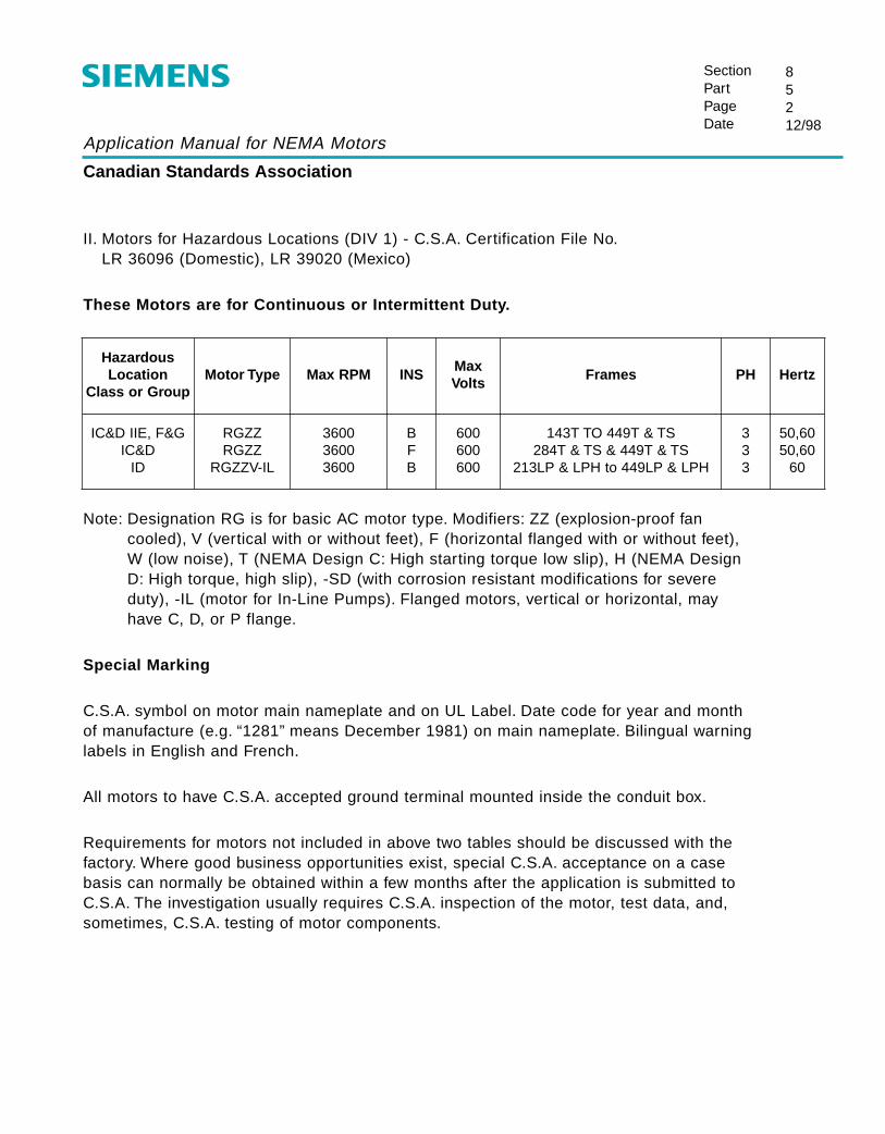
Application Manual for NEMA Motors
Canadian Standards Association
SectionPartPageDate
85212/98
II. Motors for Hazardous Locations (DIV 1) - C.S.A. Certification File No.LR 36096 (Domestic), LR 39020 (Mexico)
These Motors are for Continuous or Intermittent Duty.
Note: Designation RG is for basic AC motor type. Modifiers: ZZ (explosion-proof fancooled), V (vertical with or without feet), F (horizontal flanged with or without feet), W (low noise), T (NEMA Design C: High starting torque low slip), H (NEMA DesignD: High torque, high slip), -SD (with corrosion resistant modifications for severeduty), -IL (motor for In-Line Pumps). Flanged motors, vertical or horizontal, mayhave C, D, or P flange.
Special Marking
C.S.A. symbol on motor main nameplate and on UL Label. Date code for year and monthof manufacture (e.g. “1281” means December 1981) on main nameplate. Bilingual warninglabels in English and French.
All motors to have C.S.A. accepted ground terminal mounted inside the conduit box.
Requirements for motors not included in above two tables should be discussed with thefactory. Where good business opportunities exist, special C.S.A. acceptance on a casebasis can normally be obtained within a few months after the application is submitted toC.S.A. The investigation usually requires C.S.A. inspection of the motor, test data, and,sometimes, C.S.A. testing of motor components.
HazardousLocation
Class or GroupMotor Type Max RPM INS
MaxVolts
Frames PH Hertz
IC&D IIE, F&GIC&D
ID
RGZZRGZZ
RGZZV-IL
360036003600
BFB
600600600
143T TO 449T & TS284T & TS & 449T & TS
213LP & LPH to 449LP & LPH
333
50,6050,60
60
Application Manual for NEMA Motors
Standards Agencies’ Addresses
SectionPartPageDate
86112/98
To obtain catalogs or purchase standards, contact the appropriate organization below:
N.E.M.A. U.L.1300 North 17th Street 333 Pfingsten RoadSuite 1847 Northbrook, Illinois 60062-2096Rosslyn, Virginia 22209 Voice line: (847) 272-8800Voice line: (703) 841-3200
C.S.A.IEEE 178 Rexdale Boulevard445 Hoes Lane Rexdale (Toronto)P.O. Box 1331 Ontario, CanadaPiscataway, New Jersey 08855-1331 M9W 1R3Voice line: (800) 678-4333 Voice line: (416) 747-4044FAX line: (908) 981-9667 FAX line: (416) 747-2475
A.P.I.2101 “L” Street, NorthwestWashington D.C. 20037Voice line: (202) 682-8000
N.E.C.National Fire Protection Association1 Batterymarch ParkP.O. Box 9146Quincy, Massachusetts 02269-9703Voice line: (800) 344-3555

Application Manual for NEMA Motors
SectionPartPageDate
87112/98
EG-KonformitätserklärungNo. 664.11 003.02 / 03.96
Bevollmächtigter: Siemens AktiengesellschaftBereich Antriebs-, Schalt- und InstallationstechnikGeschäftsgebiet Niederspannungsmotoren
Anschrift: Siemensstrße 15D-97615 Bad Neustadt a. d. Saale
Hersteller: Siemens Energy & Automation, Inc.Industrial Products Division
Produktbezeichnug: Drehstrom-Asynchronmotor mit KäfigläuferTyp RG, RGZ, RGZSD, RGZE, RGZESD, 1LA.
RGF, RGZF, RGZFSD, RGZFE, & RGZFESDShaft Height: 2.2 - 11.0 inchesOutputs up to 450 HP
Das bezeichnete Produkt stimmt mit den Vorschriften folgender Europäischer Richtlinien überein:
73/23/EWG Richtlinie des Rates zur Angleichung der Rechtsvorschriften der Mitgliedstaatenbetreffend elektrischer Betriebsmittel zur Verwendung innerhalb bestimmterSpannungsgrenzen, geändert durch RL 93/68/EWG des Rates
Die Übereinstimmung mit den Vorschriften dieser Richtlinien wird nachgewiesen durch dievollständige Einhaltung folgender Normen:
EN 60034-1 EN 60034-5 EN 60034-6 EN 60034-9 EN 60204-1
Erstmalige Anbringung der CE - Kennzeichnung: 96
Diese Erklärung ist keine Zusicherung von Eigenschaften im Sinne der Produkthaftung.Die Sicherheitshinweise der Produktdokumentation sind zu beachten.
Application Manual for NEMA Motors
SectionPartPageDate
87212/98
EC declaration of conformityNo. 664.11 003.02 / 03.96
Authorized: Siemens AktiengesellschaftBereich Antriebs-, Schalt- und InstallationstechnikGeschäftsgebiet Niederspannungsmotoren
Address: Siemensstrße 15D-97615 Bad Neustadt a. d. Saale
Manufacturer: Siemens Energy & Automation, Inc.Industrial Products Division
Product Description: Three-Phase Induction Machine with Cage RotorTyp RG, RGZ, RGZSD, RGZE, RGZESD, 1LA.
RGF, RGZF, RGZFSD, RGZFE, & RGZFESDShaft Height: 2.2 - 11.0 inchesOutputs up to 450 HP
The named product is in conformity with the requirements of the following European Directive:
73/23/EWG Council Directive on the approximation of the laws of the Member States relating toelectrical equipment for use within certain voltage limits, amended by CouncilDirective RL 93/68/EEC
Conformity with the requirements of these Directives is testified by complete adherence to mefollowing standards:
EN 60034-1 EN 60034-5 EN 60034-6 EN 60034-9 EN 60204-1
CE symbol first displayed: 96
This Declaration does not give assurance of properties within the meaning of product liability.The safety instructions provided in the product documentation must be observed.

C
ES
N-W
B2F
BS BAKK
V
Application Manual for NEMA Motors
NMCD-L4000-0897 ©1997 Siemens Energy & Automation, Inc. All Rights ReservedThis document, in part, contains information confidential and proprietary to Siemens Energy & Automation, Inc. (SE&A) and is to be usedsolely for the purpose for which it is furnished and returned to SE&A upon request. This document and the information contained thereinshall not be altered, reproduced, transmitted, or disclosed to any third party or otherwise used without the express written consent of SE&A.All information herein is subject to change without notice.

NEMA Frames Application Manual
Table of Contents
Page DateSection 1 Index of Products
1 Product Range and Scope 1 6/972 Construction Features 1 6/973 Motor Type Designations 1 6/97
Section 2 Basic Motor Terminology and Theory1 Motor Terminology 1-4 6/972 Basic Noise Theory 1-6 6/973 Effect of Power Supply Variations 7 6/97
Section 3 Descriptive Material 1 6/97
Section 4 Dimensional Drawings
Horizontal Motors1 Slide Bases 1-5 6/972 Open Drip-proof 1-14 6/973 Totally Enclosed Fan Cooled 1-31 6/974 Severe Duty 1-39 6/975 Explosion-proof 1-24 6/97
Vertical Motors6 Totally Enclosed Fan Cooled 1-16 6/976 Hollow Shaft 17-19 6/977 Severe Duty 1-27 6/978 Explosion-proof 1-27 6/97
Section 5 Electrical Data1 Frame Assignments 1-5 6/972 Speed Torque Curves 1-91 6/973 Insulation System 1-2 6/974 External Load WK2 Capabilities 1-4 6/975 Connection Diagrams 1-4 6/976 Temperature Rise 1 6/97

Application Manual for NEMA Motors
Table of Contents
Page DateSection 6 Mechanical Data
1 Conduit Boxes 1-3 6/972 Standard Rotor Balance 1-2 6/973 Standard Shaft Material 1 6/974 Motor Bearing Sizes 1-6 6/975 Belted Service 1 6/976 Rotor Weight and WK2 1-5 6/977 Paint Standard 1 6/978 Packaging 1 6/979 Noise Data 6/97
10 Modifications for Low Temperature 1 6/97
Section 7 Accessories1 Space Heaters 1-2 6/972 Thermal Protective Devices 1-2 6/97
Section 8 Standards1 National Electrical Manufactures Association 1-2 6/972 The Institute of Electrical and Electronic Engineers 1-2 6/973 American Petroleum Institute 1 6/974 Hazardous Location Classifications and
Underwriters Laboratory 1-7 6/975 Canadian Standards Association 1-2 6/976 Standards Agencies’ Addresses 1-7 6/977 CE Mark 1-2 6/97
Section 9 Tests1 Standard Commercial Test 1 6/972 Complete Test 1 6/973 Noise Test 1 6/97
Section 10 Special Applications and Information1 Power Factor Correction 1-4 6/972 Methods of Starting 3 Phase Motors 1-14 6/973 Duty Cycles and Inertia 1-7 6/974 Horsepower Determination 1 6/975 General Formulas 1-3 6/97

NEMA Frames Application Manual
Mechanical Data
SectionPartPageDate
60Index6/97
Page DatePart 1 Conduit Boxes 1-3 6/97
Part 2 RotorsStandard Rotor Balance 1 6/97Rotor End Play Limits 2 6/97
Part 3 Standard Shaft Material 1 6/97
Part 4 BearingsHorizontal Motor Bearing Sizes 1-2 6/97Grease and Relubrication 3 6/97Bearing Grease Capacity 4 6/97Vertical Motor Bearing Sizes 5-6 6/97
Part 5 Belted Service 1 6/97
Part 6 Rotor Weight and Inertias 1-5 6/97
Part 7 Paint Standard 1 6/97
Part 8 Packaging 1 6/97Packaging Dimensions Chart 2 6/97
Part 9 Noise Data 1-3 6/97
Part 10 Modifications for Low Temperature 1 6/97

Application Manual for NEMA Motors
Standard Conduit Boxes — TEFC-standard duty — Type RGZP
SectionPartPageDate
61112/98
C
D
BE
A
FG N.P.T.
Frame
External Dimensions (in) Approx.internalvolume
(in3)
no. ofcoverboltsA B C D E F
G
NPT Max.Cond.
140 2.60 4.21 3.70 2.99 2.17 0.96 0.75 28 2
180 2.60 4.21 3.70 2.99 2.17 0.96 0.75 28 2
210 3.60 6.10 5.47 4.33 2.90 1.34 1.00 58 2
250 3.60 6.10 5.47 4.33 2.90 1.34 1.25 58 2
*280 5.12 7.69 6.50 5.50 5.00 2.00 - 2.00 189 1
*320 5.12 7.69 6.50 5.50 5.00 2.00 - 2.50 189 1
*360 7.19 9.38 7.00 6.00 6.25 3.38 - 3.00 316 1
*400 7.19 9.38 7.00 6.00 6.25 3.38 - 3.00 316 1
440 8.06 12.31 10.50 9.50 7.00 3.50 3.00 762 4
* 140-250 frames are cast aluminum, 280-400 frames have steel conduit boxes

Application Manual for NEMA Motors
Standard Conduit Boxes — TEFC-severe duty — Types RGZPSD, RGZESD
SectionPartPageDate
61212/98
F
B
E
C
D
A
G N.P.T.
Frame
External Dimensions (in) Approx.internalvolume
(in3)
no. ofcoverboltsA B C D E F
140 2.68 4.6 4.15 3.58 2.36 1.00 0.75 27 4
180 3.07 4.76 4.49 3.92 2.48 1.24 0.75 36 4
210 3.86 7.05 5.49 4.90 3.66 1.56 1.00 85 4
250 3.86 7.05 5.49 4.90 3.66 1.56 1.25 85 4
280 5.50 8.31 7.12 6.38 4.75 2.44 1.50 226 4
320 6.44 10.00 8.50 7.62 5.50 3.00 2.00 282 4
360 8.06 12.31 10.50 9.50 7.00 3.50 3.00 762 4
400 8.06 12.31 10.50 9.50 7.00 3.50 3.00 762 4
440 8.06 12.31 10.50 9.50 7.00 3.50 3.00 762 4
G
S449 10.19 15.70 13.50 12.50 8.50 5.00 4.00 1696 4
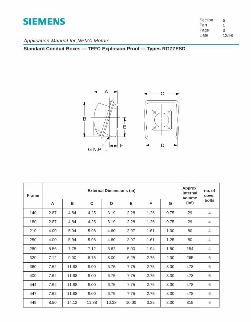
Application Manual for NEMA Motors
Standard Conduit Boxes — TEFC Explosion Proof — Types RGZZESD
SectionPartPageDate
61312/98
B
E
F
C
D
A
G N.P.T.
FrameExternal Dimensions (in)
Approx.internalvolume
(in3)
no. ofcoverbolts
A B C D E F
140 2.87 4.84 4.25 3.19 2.28 1.26 0.75 29 4
180 2.87 4.84 4.25 3.19 2.28 1.26 0.75 29 4
210 4.00 5.94 5.98 4.60 2.97 1.61 1.00 80 4
250 4.00 5.94 5.98 4.60 2.97 1.61 1.25 80 4
280 5.56 7.75 7.12 6.62 5.00 1.94 1.50 154 4
320 7.12 9.00 8.75 8.00 6.25 2.75 2.00 265 6
360 7.62 11.88 9.00 6.75 7.75 2.75 3.00 478 6
400 7.62 11.88 9.00 6.75 7.75 2.75 3.00 478 6
444 7.62 11.88 9.00 6.75 7.75 2.75 3.00 478 6
G
447 7.62 11.88 9.00 6.75 7.75 2.75 3.00 478 6
449 8.50 14.12 11.38 10.38 10.00 3.38 3.00 815 6

Application Manual for NEMA Motors
Standard Rotor Balance
SectionPartPageDate
62112/98
The rotors of all motors are dynamically balanced in precisionbalancing machines to a degree that insures that the vibration measured on the bearing housing willbe below the limits established by NEMA MG1-Part 7.
* For roller bearing motors axial limit is 0.001.** This is not a present NEMA standard (was in previous standard MG1.12.06), but can be
calculated based upon velocity and speed.
The above limits apply to motors on an elastic mounting per NEMA MG1-Part 7.06.1.
When required precision balance and extra precision balance are available, refer to factory forvibration levels and pricing.
NEMA Limits Std. Siemens' LimitsSpeedRPM Velocity
in/secDisplacement
P-P InchesVelocityin/sec
DisplacementP-P Inches
3600 0.15 0.001 ** 0.08 .0005 *
1800 0.15 0.0015 ** 0.08 .0005 *
1200 0.15 0.002 ** 0.08 .0005 *
900 0.12 0.0025 ** 0.08 .0005 *
Application Manual for NEMA Motors
Rotor Endplay Limits
SectionPartPageDate
62212/98
The Medallion motor line features wavy (spring) washer loading which causes perceivedendplay to be zero under normal operating conditions.
Under conditions of excessive thrust loading, some limited endplay due to compression ofthe wavy washer may be observed.

Application Manual for NEMA Motors
Standard Shaft Material
SectionPartPageDate
63112/98
The standard shaft material supplied on motors is AISI (or SAE) 1045. It is a hot rolled, medium carbon, fine grain steel formed in round bars of special quality and straightness.
Typical Composition (%)Carbon .45, Manganese .70, Phosphorus .007, Sulfur .025, Silicone .27
Tensile strength (PSI) 82,000 min.Yield strength (PSI) 45,000 min.Brinell 163 min.
Special steels including high strength and stainless are available on request.Refer to factory for pricing.

Application Manual for NEMA Motors
Standard Bearings for NEMA Frames — Horizontal MotorsTotally Enclosed Fan Cooled (TEFC) — Standard Duty — Severe Duty
SectionPartPageDate
64112/00
TEFC — Standard DutyType RGZ
TEFC — Standard DutyEPAct Efficiency
Type RGZP
TEFC — EPAct EfficiencySevere DutyType RGZPSD
TEFC — Premium EfficiencySevere Duty
Types RGZESD, RGZESDX
Drive End Opposite Drive End Drive End Opposite Drive End Drive End Opposite Drive End Drive End Opposite Drive End
Frame
AFBMA no. Size AFBMA no. Size AFBMA no. Size AFBMA no. Size AFBMA no. Size AFBMA no. Size AFBMA no. Size AFBMA no. Size
143T - 145T 25BC02JEE3 6205 17BC02JEE3 6203 25BC02JP3 6205 17BC02JP3 6203 25BC02JP3 6205 25BC02JP3 6205 25BC02JP3 6205 25BC02JP3 6205
182T - 184T 30BC02JEE3 6206 20BC02JEE3 6204 30BC02JP3 6206 20BC02JP3 6204 30BC02JP3 6206 30BC02JP3 6206 30BC02JP3 6206 30BC02JP3 6206
213T - 215T 40BC02JEE3 6208 30BC02JEE3 6206 40BC02JP3 6208 30BC02JP3 6206 40BC02JP3 6208 40BC02JP3 6208 40BC02JP3 6208 40BC02JP3 6208
254T - 256T 45BC03JEE3 6209 40BC02JEE3 6208 45BC03JP3 6209 40BC02JP3 6208 45BC03JP3 6309 45BC03JP3 6309 45BC03JP3 6309 45BC03JP3 6309
284TS - 286TS 50BC03JPP3 6310 50BC02JPP3 6210 50BC03JP3 6310 50BC02JP3 6210 50BC03JP3 6310 50BC02JP3 6210 50BC03JP3 6310 50BC03JP3 6310
284T - 286T 50BC03JPP3 6310 50BC02JPP3 6210 50BC03JP3 6310 50BC02JP3 6210 50BC03JP3 6310 50BC02JP3 6210 50BC03JP3 6310 50BC03JP3 6310
324TS - 326TS 60BC03JPP3 6312 50BC02JPP3 6210 60BC03JP3 6312 50BC02JP3 6210 60BC03JP3 6312 50BC02JP3 6210 60BC03JP3 6312 60BC03JP3 6312
324T - 326T 60BC03JPP3 6312 50BC02JPP3 6210 60BC03JP3 6312 50BC02JP3 6210 60BC03JP3 6312 50BC02JP3 6210 60BC03JP3 6312 60BC03JP3 6312
364TS - 365TS 70BC03JPP3 6314 50BC02JPP3 6210 70BC03JP3 6314 50BC02JP3 6210 70BC03JP3 6314 50BC02JP3 6210 70BC03JP3 6314 70BC03JP3 6314
364T - 365T 70BC03JPP3 6314 50BC02JPP3 6210 70BC03JP3 6314 50BC02JP3 6210 70BC03JP3 6314 50BC02JP3 6210 70BC03JP3 6314 70BC03JP3 6314
404TS - 405TS 80BC03JPP3 6316 80BC03JPP3 6316 80BC03JP3 6316 80BC03JP3 6316 80BC03JP3 6316 80BC03JP3 6316 80BC03JP3 6316 80BC03JP3 6316
404T - 405T 80BC03JPP3 6316 80BC03JPP3 6316 80BC03JP3 6316 80BC03JP3 6316 80BC03JP3 6316 80BC03JP3 6316 80BC03JP3 6316 80BC03JP3 6316
444TS - 445TS 80BC03JPP3 6316 80BC03JPP3 6316 80BC03JP3 6316 80BC03JP3 6316 80BC03JP3 6316 80BC03JP3 6316 80BC03JP3 6316 80BC03JP3 6316
444T - 445T 90RU03M0 NU318 80BC03JPP3 6316 90RU03M0 NU318 80BC03JP3 6316 90RU03M0 NU318 80BC03JP3 6316 90RU03M0 NU318 80BC03JP3 6316
447TS - 449TS 80BC03JPP3 6316 80BC03JPP3 6316 80BC03JP3 6316 80BC03JP3 6316 80BC03JP3 6316 80BC03JP3 6316 80BC03JP3 6316 80BC03JP3 6316
447T - 449T 100RU03M0 NU320 80BC03JPP3 6316 100RU03M0 NU320 80BC03JP3 6316 100RU03M0 NU320 80BC03JP3 6316 100RU03M0 NU320 80BC03JP3 6316
S449SS – – – – – – – – 75BC03JP3 6315 75BC03JP3 6315 75BC03JP3 6315 75BC03JP3 6315
S449LS – – – – – – – – 100RU03M0 NU320 75BC03JP3 6315 100RU03M0 NU320 75BC03JP3 6315

Application Manual for NEMA Motors
Standard Bearings for NEMA Frames — Horizontal MotorsOpen Drip-Proof and Explosion-Proof
SectionPartPageDate
64212/00
Open Drip-ProofTypes RGE1, RGE
Explosion-ProofTypes RGZZESD
Drive End Opposite Drive End Drive End Opposite Drive EndFrame
AFBMA no. Size AFBMA no. Size AFBMA no. Size AFBMA no. Size
143T - 145T 25BC02JEE3 6205 25BC02JEE3 6205 25BC02JP3 6205 25BC02JP3 6205
182T - 184T 30BC02JEE3 6206 25BC02JEE3 6205 30BC02JP3 6206 30BC02JP3 6206
213T - 215T 40BC02JEE3 6208 30BC02JEE3 6206 40BC02JP3 6208 40BC02JP3 6208
254T - 256T 45BC03JEE3 6309 35BC02JEE3 6207 45BC03JP3 6309 45BC03JP3 6309
284TS - 286TS 45BC02JPP3 6209 45BC02JPP3 6209 50BC03JP3 6310 50BC03JP3 6310
284T - 286T 55BC03JPP3 6311 45BC02JPP3 6209 50BC03JP3 6310 50BC03JP3 6310
324TS - 326TS 55BC03JPP3 6311 55BC03JPP3 6311 60BC03JP3 6312 60BC03JP3 6312
324T - 326T 60BC03JPP3 6312 55BC03JPP3 6311 60BC03JP3 6312 60BC03JP3 6312
364TS - 365TS 55BC03JPP3 6311 55BC03JPP3 6311 70BC03JP3 6314 70BC03JP3 6314
364T - 365T 70BC03JPP3 6314 55BC03JPP3 6311 70BC03JP3 6314 70BC03JP3 6314
404TS - 405TS 65BC03JPP3 6313 65BC03JPP3 6313 80BC03JP3 6316 80BC03JP3 6316
404T - 405T 80BC03JPP3 6316 65BC03JPP3 6313 80BC03JP3 6316 80BC03JP3 6316
444TS - 445TS 65BC03JPP3 6313 65BC03JPP3 6313 80BC03JP3 6316 80BC03JP3 6316
444T - 445T 90BC03JPP3 6318 65BC03JPP3 6313 90RU03M0 NU318 80BC03JP3 6316
447TS - 449TS 65BC03JPP3 6313 65BC03JPP3 6313 80BC03JP3 6316 80BC03JP3 6316
447T - 449T 90RU03M0 NU318 65BC03JPP3 6313 100RU03M0 NU320 80BC03JP3 6316
S449SS – – – – – – – –
S449LS – – – – – – – –
Application Manual for NEMA Motors
Grease and Relubricating Instructions
SectionPartPageDate
64312/98
Grease and Rulubricating Instructions
To assist our customers in securing trouble-free service from electric motors, Siemens uses double-shielded bearings on most NEMA size motors.
This type of bearing allows controlled migration of grease into the bearing, yet protects againstovergreasing.
Replenishment grease for ball bearings should have a wide usable temperature range (-20°F to+350°F) and be made with a polyurea thickener and high quality oil with an NLGI #2 consistency.Chevron SRI #2 meets these requirements.
For roller bearing grease replenishment, use the grease recommended on the motor lubricationinstruction plate.
Normal Lubrication Sequence
1. Stop the motor. Lock out the switch.
2. Thoroughly clean off and remove the grease inlet and drain pipe plugs from bearing housing.
3. Remove hardened grease from drains with stiff wire or rod.
4. Add grease to inlet until a small amount of new grease is forced out drain.
5. Remove excess grease from ports, replace inlet plugs and run motor 1/2 hour before replacingdrain plugs.
6. Put motor back in operation.
RelubricationFrequency Type of Service
6 months normal-duty in relativelyclean & dry environments
3 months
heavy-duty in dirty, dustylocations, high ambients,moisture laden atmosphere orincreased vibration levels

Application Manual for NEMA Motors
Bearing Grease Capacity
SectionPartPageDate
6446/97
Bearing Grease Capacity
Frame Shaft End Bearing Opposite End Bearing
Direct Connected Belted
140T 0.2 oz. 0.2 oz. 0.2 oz.
180T 0.3 0.3 0.3
210T 1.6 1.6 1.6
250T 2.3 2.3 2.3
280T(S) 2.6 2.6 2.6
320T(S) 5.5 5.5 5.5
360T(S) 7.5 7.5 7.5
400T(S) 7.5 7.5 7.5
440T(S) 7.5 14.5 7.5
The grease capacity given is for that space in the bearing housing between the shield and the outside of the motor.

Application Manual for NEMA Motors
Standard Ball Bearings for NEM A Frames “P” Base — Vertical MotorsTotally Enclosed Fan Cooled (TEFC) and Explosion-Proof
SectionPartPageDate
64512/98
Normal Thrust Types: RGZVESD, RGZZVESD
Medium ThrustTypes: RGZVMT ESD, RGZZVMTESD
Drive End Opposite Drive End Drive End Opposite Drive EndFrame
AFBMA no. Size AFBMA no. Size AFBMA no. Size AFBMA no. Size
143HP - 145HP 30BC02J3 6206 30BC02J3 6206 - - - 6203
182HP - 184HP 30BC02J3 6206 30BC02J3 6206 - - - 6204
213HP - 215HP 45BC02J3 6209 45BC03J3 6309 - - - 6206
254HP - 256HP 45BC03J3 6309 45BC03J3 6309 - - - 6208
284HP - 286HP 60BC03JP3 6312 50BC03JPP3 6310 60BC03JP3 6312 50BT03XXXDO50BZ03K
7310QJ310
324HP - 326HP 60BC03JP3 6312 60BC03JPP3 6312 60BC03JP3 6312 55BT03XXXDO55BZ03K
7311QJ311
364HP - 365HP 60BC03JP3 6312 70BC03JPP3 6314 60BC03JP3 6312 55BT03XXXDO55BZ03K
7311QJ311
404HP - 405HP 80BC03JPP3 6316 80BC03JPP3 6316 80BT03XXXD0 7316 80BC03JPP3 6316
444HP - 449HP(2 pole)
80BC03JPP3 6316 80BC03JPP3 6316 80BT03XXXD0 7316 80BC03JPP3 6316
444HP - 449HP(4 pole & slower)
90BC03JPP3 6318 80BC03JPP3 6316 90BT03XXXD0 7318 80BC03JPP3 6316

Application Manual for NEMA Motors
Standard Ball Bearings for NEM A Frames “P” Base — Vertical MotorsTotally Enclosed Fan Cooled (TEFC) and Explosion-Proof
SectionPartPageDate
64612/98
Vertical In-LineTypes: RGZVILESD, RGZZVILESD
Drive End Opposite Drive EndFrame
AFBMA no. Size AFBMA no. Size
143LP - 145LP 30BC02J3 6206 35BT03MR (duplex) 7306
213LP - 215LP 45BC02J3 6209 45BT03MR3 (duplex) 7309
254LP - 256LP 45BC03J3 6309 45BT03MR3 (duplex) 7309
284LP(H) - 286LP(H) 60BC03JP3 6312 50BT03JR (duplex) 7310
324LP - 326LP 60BC03JP3 6312 55BT03JR (duplex) 7311
364LP - 365LP 60BC03JP3 6312 55BT03JR (duplex) 7311
404LP - 405LP 80BC03JPP3 6316 55BT03JR (duplex) 7311
444LP - 445LP 80BC03JPP3 6316 55BT03JR (duplex) 7311
182LP - 184LP 30BC02J3 6206 30BT03MR (duplex) 7306

Application Manual for NEMA Motors
ABMA Nomenclature — Ball Bearings
SectionPartPageDate
64712/98
BearingBore
D D D
BearingTypeL L L
DimensionSeries
D DModifications
Fitup &Tolerance
D** D**
L designates a letterD designates a digit
L LL* L*
Bea
ring
Bor
e in
Mill
imet
ers
(2 o
r 3
Dig
its)
Typ
e of
Bal
l bea
ring
(2 o
r 3
Lette
rs)
Dim
ensi
on S
erie
s
Typ
e of
Cag
e or
Bal
l Ret
aine
r
Col
umn
2 or
3 U
sed
for
R, T
, or
U
Inte
rnal
Cle
aran
ces
Tol
eran
ces
e.g., 203 = 17, 204 = 20, 307 = 35, 222 = 110, i.e., the last two digits are multiplied by 5 to obtain the bore,excepting the 203 or 303 size bearing which is 17.
Example: 35BC02JPP3 - Standard deep groove, light series, standard steel cage, double shielded, loose fitup and standardtolerances 6207ZZC3 (SKF) or equivalent.
Example: SSBTO3JR - This is a pair of 7313BECB (SKF) angular contact bearings mounted back to back, standard fitup.* The letters for columns 2, 3 and 4 of modifications are omitted if none are applicable. If column 4 is applicable but not 3, or 2 and 3, an X or XX is used in column 3, or 2 and 3, e.g., 35 BC02J03 or 35 BT03MXXD03** If these three columns are omitted, standard fitup, tolerances, and greases are implied
G - Snap ring and groove in outer raceD - Single bearing modified for duplex mounting
0 - Standard fitup - AFBMA 0 or C/03 - Loose internal fitup - AFBMA 3 or C/34 - Looser than C/3 AFBMA 4 or C/4
0 - Standard tolerances - ABEC 13 - More precision than 0 ABEC 35 - More precision than 3 - ABEC 5
BC - Standard deep groove ball bearing, e.g. 6308 (SKF)BL - Maximum capacity ball bearing with filling slot, e.g. 308M (SKF)BT - Angular contact thrust bearing, e.g., 7313BE (SKF)
10 - Extra light, e.g. 6000 (SKF)02 - Light, e.g. 6200 (SKF)03 - Medium, e.g. 6300 (SKF)32 - Light series wide cartridge type sealed bearings, e.g., 200-SZZC (SKF)33 - Medium series with wide cartridge type sealed bearings, e.g., 300 SZZC (SKF)
J - Standard - steel, sheet or strip form, centered by the ballsK - Bronze or brass, not sheet or strip, centered by one raceM - Bronze or brass, not sheet or strip, centered by the ballsD - Non-metallic (phenolic), centered by one raceX - Any type of cage Y - Non-ferrous metal, sheet or strip form, center
P - Single shielded - permanently fastenedPP - Double shielded - permanently fastenedE - Single sealed - permanently fastenedEE - Double sealed - permanently fastenedKK - Double labyrinth seals for cartridge bearingsR - Pair of bearings modified for duplex mounting - back to backT - Pair of bearings modified for duplex mounting - in tandemU - Pair of bearings modified for duplex mounting - face to faceX - None of the above - see footnote *XX - None of the above - see footnote *
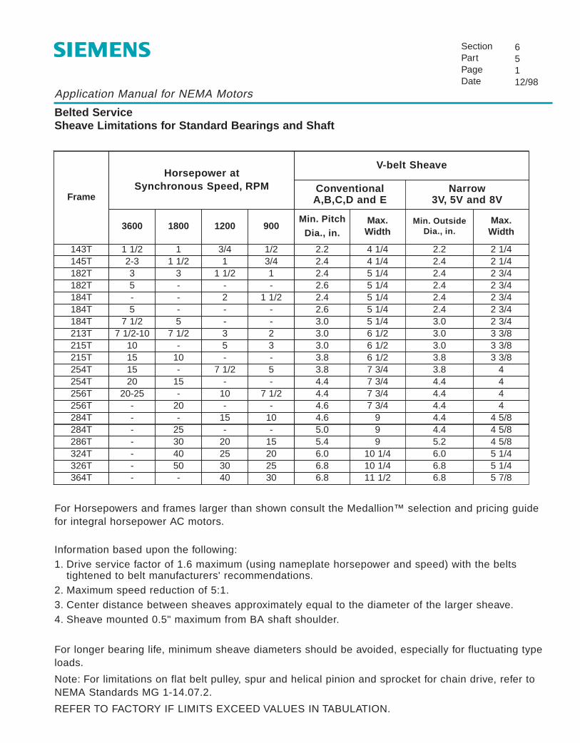
Application Manual for NEMA Motors
Belted ServiceSheave Limitations for Standard Bearings and Shaft
SectionPartPageDate
65112/98
Frame
Horsepower at Synchronous Speed, RPM
V-belt Sheave
ConventionalA,B,C,D and E
Narrow3V, 5V and 8V
3600 1800 1200 900Min. Pitch
Dia., in.Max.Width
Min. OutsideDia., in.
Max.Width
143T 1 1/2 1 3/4 1/2 2.2 4 1/4 2.2 2 1/4145T 2-3 1 1/2 1 3/4 2.4 4 1/4 2.4 2 1/4182T 3 3 1 1/2 1 2.4 5 1/4 2.4 2 3/4182T 5 - - - 2.6 5 1/4 2.4 2 3/4184T - - 2 1 1/2 2.4 5 1/4 2.4 2 3/4184T 5 - - - 2.6 5 1/4 2.4 2 3/4184T 7 1/2 5 - - 3.0 5 1/4 3.0 2 3/4213T 7 1/2-10 7 1/2 3 2 3.0 6 1/2 3.0 3 3/8215T 10 - 5 3 3.0 6 1/2 3.0 3 3/8215T 15 10 - - 3.8 6 1/2 3.8 3 3/8254T 15 - 7 1/2 5 3.8 7 3/4 3.8 4254T 20 15 - - 4.4 7 3/4 4.4 4256T 20-25 - 10 7 1/2 4.4 7 3/4 4.4 4256T - 20 - - 4.6 7 3/4 4.4 4284T - - 15 10 4.6 9 4.4 4 5/8284T - 25 - - 5.0 9 4.4 4 5/8286T - 30 20 15 5.4 9 5.2 4 5/8324T - 40 25 20 6.0 10 1/4 6.0 5 1/4326T - 50 30 25 6.8 10 1/4 6.8 5 1/4364T - - 40 30 6.8 11 1/2 6.8 5 7/8
For Horsepowers and frames larger than shown consult the Medallion™ selection and pricing guidefor integral horsepower AC motors.
Information based upon the following:1. Drive service factor of 1.6 maximum (using nameplate horsepower and speed) with the belts
tightened to belt manufacturers' recommendations.2. Maximum speed reduction of 5:1.3. Center distance between sheaves approximately equal to the diameter of the larger sheave.4. Sheave mounted 0.5" maximum from BA shaft shoulder.
For longer bearing life, minimum sheave diameters should be avoided, especially for fluctuating typeloads.
Note: For limitations on flat belt pulley, spur and helical pinion and sprocket for chain drive, refer toNEMA Standards MG 1-14.07.2.
REFER TO FACTORY IF LIMITS EXCEED VALUES IN TABULATION.

Application Manual for NEMA Motors
Rotor Weights and Inertias
SectionPartPageDate
6616/97
Epact EfficiencyTotally Enclosed
Fan Cooled (TEFC) Types RGZP, RGZPSD
Premium EfficiencyTotally Enclosed
Fan Cooled (TEFC)Types RGZE, RGZESD,
RGZZESD
Standard EfficiencyOpen Drip-Proof (ODP)
Type RGE1
HP RPM Frame Weight (lb) Inertia (lb-ft2) Weight (lb) Inertia (lb-ft2) Weight (lb) Inertia (lb-ft2)
0.75 1200 143T 7.4 0.05 8.0 0.06 11 0.110.75 900 145T 10 0.08 11 0.09 - -
1 1800 143T 7.4 0.05 8.7 0.06 7.7 0.071 1200 145T 9.7 0.07 10 0.08 11 0.111 900 182T 12 0.11 14 0.14 - -
1.5 3600 143T 7.4 0.05 8.9 0.07 11 0.111.5 1800 145T 7.5 0.05 9.1 0.06 11 0.111.5 1200 182T 12 0.11 14 0.14 18 0.281.5 900 184T 16 0.16 18 0.18 24 0.622 3600 145T 9.6 0.07 10 0.08 11 0.112 1800 145T 9.7 0.07 10 0.08 11 0.122 1200 184T 14 0.14 17 0.18 16 0.282 900 213T 23 0.32 23 0.32 30 0.763 3600 145T - - - - 12 0.133 3600 182T 10 0.09 12 0.11 - -3 1800 182T 12 0.11 14 0.14 15 0.233 1200 213T 22 0.28 27 0.39 24 0.453 900 215T 29 0.43 29 0.43 36 0.915 3600 182T - - - - 15 0.135 3600 184T 13 0.12 16 0.16 - -5 1800 184T 16 0.16 17 0.18 20 0.375 1200 215T 28 0.40 34 0.54 35 0.705 900 254T 46 0.94 50 1.1 53 1.8
7.5 3600 184T - - - - 18 0.197.5 3600 213T 27 0.32 32 0.43 - -7.5 1800 213T 27 0.39 31 0.50 30 0.567.5 1200 254T 44 0.95 60 1.4 59 2.27.5 900 256T 59 1.3 64 1.5 64 2.110 3600 213T - - - - 31 0.2610 3600 215T 29 0.43 31 0.49 - -10 1800 215T 32 0.51 36 0.58 35 0.7010 1200 256T 56 1.2 71 1.7 68 2.910 900 284T 81 2.6 86 2.8 83 3.615 3600 215T - - - - 38 0.3815 3600 254T 56 1.2 56 1.2 - -15 1800 254T 46 0.9 57 1.3 59 1.315 1200 284T 73 2.2 81 2.6 97 5.015 900 286T 97 3.4 105 3.8 100 4.4

Application Manual for NEMA Motors
Rotor Weights and Inertias
SectionPartPageDate
6626/97
Epact EfficiencyTotally Enclosed
Fan Cooled (TEFC) Types RGZP, RGZPSD
Premium EfficiencyTotally Enclosed
Fan Cooled (TEFC)Types RGZE, RGZESD,
RGZZESD
Standard EfficiencyOpen Drip-Proof (ODP)
Type RGE1
HP RPM Frame Weight (lb) Inertia (lb-ft2) Weight (lb) Inertia (lb-ft2) Weight (lb) Inertia (lb-ft2)
20 3600 254T - - - - 59 0.6320 3600 256T 57 1.2 58 1.3 - -20 1800 256T 59 1.3 71 1.7 68 1.720 1200 286T 86 2.8 97 3.3 115 6.120 900 324T 130 5.4 136 5.5 123 7.325 3600 256T - - - - 73 0.9125 3600 284TS 59 1.3 75 1.9 - -25 1800 284T 76 2.4 86 2.8 73 2.525 1200 324T 110 4.1 121 4.9 137 9.125 900 326T 147 6.4 153 6.5 147 930 3600 284TS - - - - 64 1.630 3600 286TS 66 1.6 85 2.3 - -30 1800 286T 86 2.8 97 3.3 86 3.130 1200 326T 122 4.9 137 5.8 146 9.730 900 364T 189 11 192 11 180 1740 3600 286TS - - - - 75 1.940 3600 324TS 90 2.6 105 3.3 - -40 1800 324T 111 4.2 119 4.7 117 5.740 1200 364T 184 11 184 11 176 1440 900 365T 228 14 231 14 205 2050 3600 324TS - - - - 95 350 3600 326TS 102 3.2 121 4.1 - -50 1800 326T 130 5.4 136 5.8 141 7.250 1200 365T 199 12 213 13.1 213.8 1850 900 404T 299 25 304 26 299 2560 3600 326TS - - - - 104 3.460 3600 364TS 120 4.3 130 5.0 - -60 1800 364T 156 8.3 173 9.6 161 1060 1200 404T 263 21 284 23 263 2160 900 405T 331 29 340 30 331 2975 3600 364TS - - - - 132 5.275 3600 365TS 139 5.5 157 6.6 - -75 1800 365T 185 11 199 12 122 1075 1200 405T 307 26 331 29 307 2675 900 444T 400 40 400 40 400 40
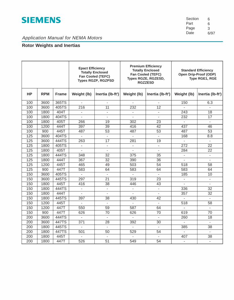
Application Manual for NEMA Motors
Rotor Weights and Inertias
SectionPartPageDate
6636/97
Epact EfficiencyTotally Enclosed
Fan Cooled (TEFC) Types RGZ P, RGZPSD
Premium EfficiencyTotally Enclosed
Fan Cooled (TEFC)Types RGZE, RGZESD,
RGZZESD
Standard EfficiencyOpen Drip-Proof (ODP)
Type RGE1, RGE
HP RPM Frame Weight (lb) Inertia (lb-ft 2) Weight (lb) Inertia (lb-ft 2) Weight (lb) Inertia (lb-ft 2)
100 3600 365TS - - - - 150 6.3100 3600 405TS 216 11 232 12 - -100 1800 404T - - - - 243 18100 1800 404TS - - - - 232 17100 1800 405T 266 19 302 23 - -100 1200 444T 397 39 416 42 437 46100 900 445T 487 53 487 53 487 53125 3600 404TS - - - - 168 8.8125 3600 444TS 263 17 281 19 - -125 1800 405TS - - - - 272 22125 1800 405T - - - - 284 22125 1800 444TS 348 32 375 35 - -125 1800 444T 367 32 390 36 - -125 1200 445T 465 49 503 54 518 58125 900 447T 583 64 583 64 583 64150 3600 405TS - - - - 185 10150 3600 445TS 297 21 319 23 - -150 1800 445T 416 38 446 43 - -150 1800 444TS - - - - 336 32150 1800 444T - - - - 357 32150 1800 445TS 397 38 430 42 - -150 1200 445T - - - - 518 58150 1200 447T 550 59 587 64 - -150 900 447T 626 70 626 70 619 70200 3600 444TS - - - - 260 18200 3600 447TS 371 28 392 30 - -200 1800 445TS - - - - 385 38200 1800 447TS 501 50 529 54 - -200 1800 445T - - - - 407 38200 1800 447T 526 51 549 54 - -

Application Manual for NEMA Motors
Rotor Weights and Inertias
SectionPartPageDate
6646/97
Standard EfficiencyTotally Enclosed
Fan Cooled (TEFC)Types RGZ, RGZSD, RGZZSD
Premium EfficiencyTotally Enclosed
Fan Cooled (TEFC)Types RGZE, RGZESD,
RGZZESD
Standard EfficiencyOpen Drip-Proof (ODP)
Type RGE
HP RPM Frame Weight (lb) Inertia (lb-ft2) Weight (lb) Inertia (lb-ft2) Weight (lb) Inertia (lb-ft2)
200 1200 447T - - - - 619 70200 1200 449T 710 79 739 85 - -200 900 449T 764 88 764 88 710 82250 3600 445TS - - - - 302 23250 3600 449TS 456 35 486 38 - -250 1800 445TS - - - - 385 38250 1800 445T - - - - 407 38250 1800 449TS 623 64 645 67 - -250 1800 449T 648 64 670 67 - -250 1200 449T 701 79 739 85 758 88300 3600 447TS - - - 347 26300 3600 449TS 456 35 484 38 - -300 1800 447TS - - - - 508 52300 1800 447T - - - - 531 53300 1800 449TS 623 64 645 67 - -300 1800 449T 648 64 670 67 591 61350 3600 447TS - - - - 347 26350 1800 447TS - - - - - -350 1800 447T - - - - 531 53400 3600 447TS - - - - 347 26400 1800 449TS - - - - - -400 1800 449T - - - - 569 58450 3600 449TS - - - - 411 31450 1800 449TS - - - - - -450 1800 449T - - - - - -
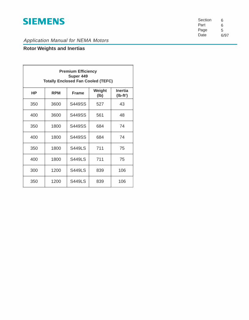
Application Manual for NEMA Motors
Rotor Weights and Inertias
SectionPartPageDate
6656/97
Premium EfficiencySuper 449
Totally Enclosed Fan Cooled (TEFC)
HP RPM FrameWeight
(lb)Inertia(lb-ft2)
350 3600 S449SS 527 43
400 3600 S449SS 561 48
350 1800 S449SS 684 74
400 1800 S449SS 684 74
350 1800 S449LS 711 75
400 1800 S449LS 711 75
300 1200 S449LS 839 106
350 1200 S449LS 839 106

Application Manual for NEMA Motors
Paint Process Standard — Little Rock Plant
SectionPartPageDate
67112/98
Surface Preparation and Primer
1. Ferrous castings are blast cleaned in accordance with standard specification SSPC-SP-6.
2. Castings are immediately primed with a lead free alkyd base primer to a thickness of 2 to 3 mils.
3. Exterior surfaces are solvent cleaned as required to remove oil or other contaminants resultingfrom manufacturing or assembly operations.
Paint
Siemens standard finish paint consists of the following:
Epoxy modified acrylic air dry enamel.Viscosity: 5--55 seconds No. 2 Zahn cup @ 77°F.Fineness: 7 N.S. units Hegeman gage:Adhension: 90% Cross-hatch test (tape)Impact resistance: 40 inch pounds direct - No cracksComposition: Lead and Chromate free
Color
Motor types RGZP-RGZPSD Gray, Types RGZESD, RGZZESD Dark Blue.
An optional paint system for extremely corrosive atmospheres is available.Refer to your Siemens Representative.
Exposed Metal Surfaces
Exposed metal surfaces such as shafts are coated with rust preventative.
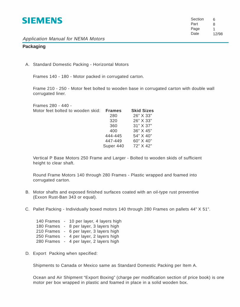
Application Manual for NEMA Motors
Packaging
SectionPartPageDate
68112/98
A. Standard Domestic Packing - Horizontal Motors
Frames 140 - 180 - Motor packed in corrugated carton.
Frame 210 - 250 - Motor feet bolted to wooden base in corrugated carton with double wallcorrugated liner.
Frames 280 - 440 - Motor feet bolted to wooden skid: Frames Skid Sizes
280 26” X 33”320 26” X 33”360 31” X 37”400 36” X 45”
444-445 54” X 40”447-449 60” X 40”
Super 440 72” X 42”
Vertical P Base Motors 250 Frame and Larger - Bolted to wooden skids of sufficient height to clear shaft.
Round Frame Motors 140 through 280 Frames - Plastic wrapped and foamed into corrugated carton.
B. Motor shafts and exposed finished surfaces coated with an oil-type rust preventive (Exxon Rust-Ban 343 or equal).
C. Pallet Packing - Individually boxed motors 140 through 280 Frames on pallets 44” X 51”.
140 Frames - 10 per layer, 4 layers high180 Frames - 8 per layer, 3 layers high210 Frames - 6 per layer, 3 layers high250 Frames - 4 per layer, 2 layers high280 Frames - 4 per layer, 2 layers high
D. Export Packing when specified:
Shipments to Canada or Mexico same as Standard Domestic Packing per Item A.
Ocean and Air Shipment “Export Boxing” (charge per modification section of price book) is onemotor per box wrapped in plastic and foamed in place in a solid wooden box.

Application Manual for NEMA Motors
Packaging Dimensions
SectionPartPageDate
68212/98
Frame Motor Type
Carton Dimensions (in) Pallet Dimensions (in)
Height Width Depth Width Depth
143 - 145 Horizontal 14.5 11.5 9
182 - 184 Horizontal 17 13.5 11.5
213 - 215 Horizontal 21.5 16.5 15.25
254 - 256 Horizontal 19 19.5 26
284 - 286 Horizontal — — — 26 33
324 - 326 Horizontal — — — 26 33
364 - 365 Horizontal — — — 31 37
404 - 405 Horizontal — — — 36 45
444 - 445 Horizontal — — — 54 40
447 - 449 Horizontal — — — 60 40
Super 440 Horizontal — — — 72 42
182 - 256 In-line Vertical — — — 28 32
284 - 365 In-line Vertical — — — 28 32
404 - 445 Vertical — — — 40 40
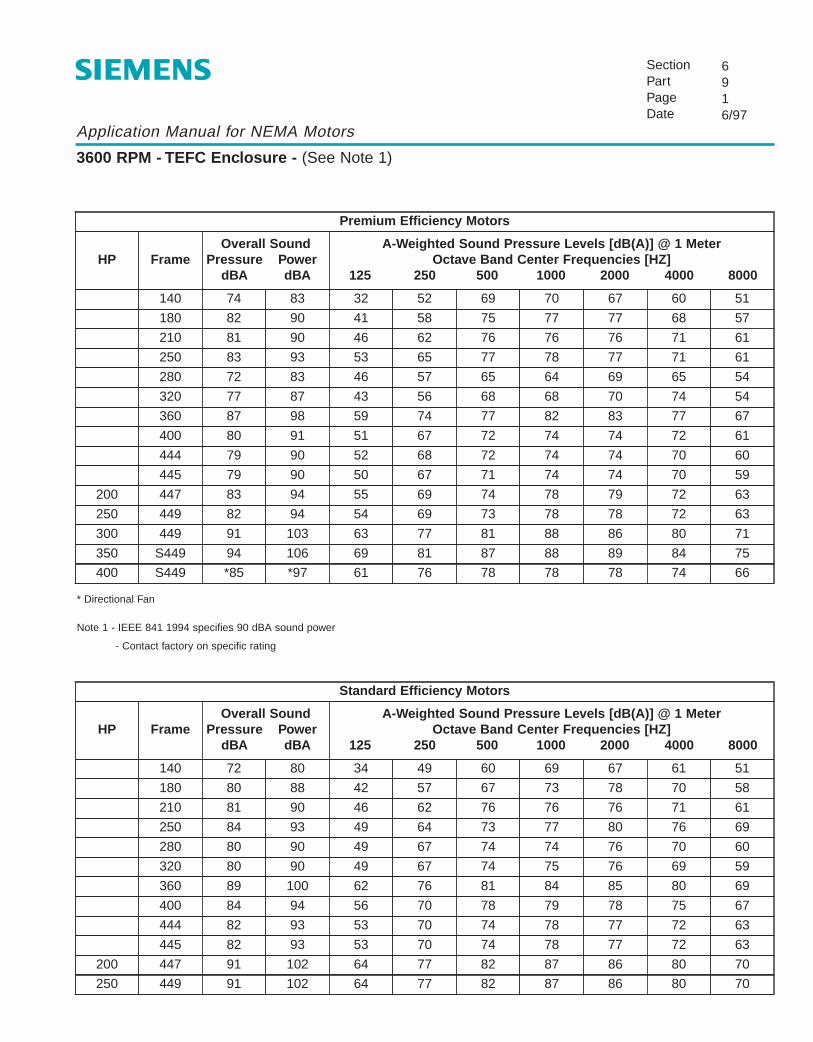
Application Manual for NEMA Motors
3600 RPM - TEFC Enclosure - (See Note 1)
SectionPartPageDate
6916/97
Premium Efficiency Motors
HP FrameOverall Sound
Pressure PowerdBA dBA
A-Weighted Sound Pressure Levels [dB(A)] @ 1 MeterOctave Band Center Frequencies [HZ]
125 250 500 1000 2000 4000 8000
140 74 83 32 52 69 70 67 60 51
250 83 93 53 65 77 78 77 71 61
280 72 83 46 57 65 64 69 65 54
320 77 87 43 56 68 68 70 74 54
360 87 98 59 74 77 82 83 77 67
400 80 91 51 67 72 74 74 72 61
444 79 90 52 68 72 74 74 70 60
445 79 90 50 67 71 74 74 70 59
200 447 83 94 55 69 74 78 79 72 63
250 449 82 94 54 69 73 78 78 72 63
300 449 91 103 63 77 81 88 86 80 71
350 S449 94 106 69 81 87 88 89 84 75
400 S449 *85 *97 61 76 78 78 78 74 66
210 81 90 46 62 76 76 76 71 61
180 82 90 41 58 75 77 77 68 57
* Directional Fan
Note 1 - IEEE 841 1994 specifies 90 dBA sound power
- Contact factory on specific rating
Standard Efficiency Motors
210 81 90 46 62 76 76 76 71
HP FrameOverall Sound
Pressure PowerdBA dBA
61
A-Weighted Sound Pressure Levels [dB(A)] @ 1 MeterOctave Band Center Frequencies [HZ]
125 250 500 1000 2000 4000 8000
180 80 88 42 57
140 72 80 34 49 60 69 67 61 51
250 84 93 49 64 73 77 80 76 69
280 80 90 49 67 74 74 76 70 60
320 80 90 49 67 74 75 76 69 59
360 89 100 62 76 81 84 85 80 69
400 84 94 56 70 78 79 78 75 67
444 82 93 53 70 74 78 77 72 63
445 82 93 53 70 74 78 77 72 63
200 447 91 102 64 77 82 87 86 80 70
250 449 91 102 64 77 82 87 86 80 70
67 73 78 70 58
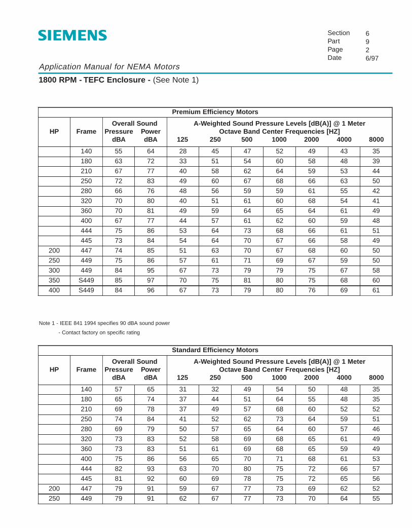
Application Manual for NEMA Motors
1800 RPM - TEFC Enclosure - (See Note 1)
SectionPartPageDate
6926/97
Premium Efficiency Motors
HP FrameOverall Sound
Pressure PowerdBA dBA
A-Weighted Sound Pressure Levels [dB(A)] @ 1 MeterOctave Band Center Frequencies [HZ]
125 250 500 1000 2000 4000 8000
210 67 77 40 58 62 64 59 53 44
250 72 83 49 60 67 68 66 63 50
280 66 76 48 56 59 59 61 55 42
320 70 80 40 51 61 60 68 54 41
360 70 81 49 59 64 65 64 61 49
400 67 77 44 57 61 62 60 59 48
444 75 86 53 64 73 68 66 61 51
445 73 84 54 64 70 67 66 58 49
200 447 74 85 51 63 70 67 68 60 50
250 449 75 86 57 61 71 69 67 59 50
300 449 84 95 67 73 79 79 75 67 58
350 S449 85 97 70 75 81 80 75 68 60
180 63 72 33 51 54 60 58 48 39
140 55 64 28 45 47 52 49 43 35
Note 1 - IEEE 841 1994 specifies 90 dBA sound power
- Contact factory on specific rating
Standard Efficiency Motors
210 69 78 37 49 57 68 60 52
HP FrameOverall Sound
Pressure PowerdBA dBA
52
A-Weighted Sound Pressure Levels [dB(A)] @ 1 MeterOctave Band Center Frequencies [HZ]
125 250 500 1000 2000 4000 8000
180 65 74 37 44
140 57 65 31 32 49 54 50 48 35
250 74 84 41 52 62 73 64 59 51
280 69 79 50 57 65 64 60 57 46
320 73 83 52 58 69 68 65 61 49
360 73 83 51 61 69 68 65 59 49
400 75 86 56 65 70 71 68 61 53
444 82 93 63 70 80 75 72 66 57
445 81 92 60 69 78 75 72 65 56
200 447 79 91 59 67 77 73 69 62 52
250 449 79 91 62 67 77 73 70 64 55
51 64 55 48 35
400 S449 84 96 67 73 79 80 76 69 61

Application Manual for NEMA Motors
1200 RPM - TEFC Enclosure - (See Note 1)
SectionPartPageDate
6936/97
Premium Efficiency Motors
HP FrameOverall Sound
Pressure PowerdBA dBA
A-Weighted Sound Pressure Levels [dB(A)] @ 1 MeterOctave Band Center Frequencies [HZ]
125 250 500 1000 2000 4000 8000
210 64 73 41 42 52 64 54 47 34
250 67 77 46 50 64 61 57 46 39
280 63 73 48 56 58 60 53 46 35
320 68 78 36 47 55 65 64 48 36
360 65 76 39 51 60 61 60 50 39
400 66 77 48 58 61 62 57 48 39
444 65 76 48 58 59 60 58 55 42
445 66 77 46 58 61 61 59 56 41
150 447 64 75 45 55 59 60 57 50 42
200 449 64 76 48 56 59 59 57 53 41
250 449 79 90 54 64 68 69 71 76 68
300 S449 74 87 57 65 69 71 66 61 56
180 54 63 35 36 46 52 47 41 31
140 50 58 26 31 43 47 40 36 31
Note 1 - IEEE 841 1994 specifies 90 dBA sound power
- Contact factory on specific rating
Standard Efficiency Motors
210 60 69 32 39 53 58 52 41
HP FrameOverall Sound
Pressure PowerdBA dBA
31
A-Weighted Sound Pressure Levels [dB(A)] @ 1 MeterOctave Band Center Frequencies [HZ]
125 250 500 1000 2000 4000 8000
180 57 66 33 33
140 50 58 28 32 45 47 38 34 28
250 68 78 44 50 63 65 59 51 42
280 61 71 38 47 58 56 53 45 34
320 65 76 45 55 62 59 57 50 38
360 64 75 39 53 61 59 58 47 41
400 68 78 47 59 60 66 59 49 38
444 70 81 59 64 66 63 60 60 46
445 70 80 49 60 65 65 60 60 46
150 447 69 80 50 58 64 64 60 53 47
200 449 67 78 49 57 63 61 59 50 43
47 54 53 36 31
350 S449 75 87 59 66 71 70 65 61 55
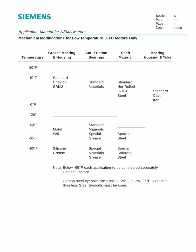
Application Manual for NEMA Motors
Mechanical Modifications for Low Temperature TEFC Motors Only
SectionPartPageDate
610112/98
Grease Bearing Anti-Friction Shaft BearingTemperature. & Housing Bearings Material Housing & Yoke
80°F
40°F StandardChevron Standard StandardSRI#2 Materials Hot-Rolled
C-1045 StandardSteel Cast
Iron0°F
-20°
-40°F StandardMobil Materials#28 Special Special
-65°F Grease Steel
-90°F Silicone Special SpecialGrease Materials Stainless
Grease Steel
Note: Below -65°F each application to be considered separately - Contact Factory.
Carbon steel eyebolts are used to -25°F, below -25°F Austenitic Stainless Steel Eyebolts must be used.

Application Manual for NEMA Motors
External Connection Diagrams - Single Speed
SectionPartPageDate
55106/01
DWG. #51-676-394 3 PHASE – 9 LEAD – WYE
VOLTS
LOW
HIGH
CONN.
YY
Y
T T1 7
L1
T1
T2 T8 T3 T9
L2
T2
L3
T3
LINES CONNECTEDTOGETHER
T1
T8T5
T2T3
T9T6
T7T4
DWG. #51-688-280
DWG. #51-676-397
T1
T8T5
T2T3
T9T6
T7T4
T1
T8T3
T7T4T9
T6
T5 T2
T4T5T4 T7 - T5 T8- T6 T9
T6
PART WINDING START3 PHASE – 9 LEAD – WYE
RUN
START
CONN.
YY
Y
L1
T1
T2 T8T1 T7 T3 T9
L2
T2
L3
T3
LINES CONNECTEDTOGETHER
T4T5T6T4T5T6
3 PHASE – 9 LEAD – DELTA
VOLTS
LOW
HIGH
CONN.
∆∆
∆
T1T6T7 T2T4T8 T3T5T9
L1
T1
L2
T2
L3
T3
LINES CONNECTEDTOGETHER
T4 T7 - T5 T8- T6 T9

Application Manual for NEMA Motors
External Connection Diagrams - Single Speed
SectionPartPageDate
55212/98
DWG. #51-406-529 PART WINDING START3 PHASE – 6 LEAD – WYE
DWG. #51-697-465 6 LEAD WYE DELTA START
LINES
START OPEN
RUN
L1
T1T2 T8T1 T7 T3 T9
L2
T2
L3
T3
T7 T1
T8
T2
T1T6
T3
T5
T4
T2
T3
T9
T7T8T9
START
RUN
CONN.
Y
∆
L1
T1T2 T4T1 T6 T3 T5
L2
T2
L3
T3
LINES CONNECTEDTOGETHER
T4T5T6

Application Manual for NEMA Motors
External Connection Diagrams - 2 Speeds
SectionPartPageDate
55312/98
CLASS OF SERVICEAND DWG. NUMBER
#51-110-063
VARIABLETORQUE
#51-110-060
CONSTANTTORQUE
#51-110-069
CONSTANTHORSE-POWER
T4
T1
T6T2
T3
T5
T4
T1
T6T2
T5
T3
SINGLE WINDING
SPEEDS
LOW SPEED
HIGH SPEED
CONN.
Y
YY
T1
L1
T6
LINES
T1T3
T4
T6T5 T2
T2
L2
T4
T3
L3
T5
T4 T5 T6 OPENT1 T2 T3 TOGETHER
SPEEDS
LOW SPEED
HIGH SPEED
CONN.
∆
YY
T1
L1
T6
LINES
T2
L2
T4
T3
L3
T5
T4 T5 T6 OPENT1 T2 T3 TOGETHER
SPEEDS
LOW SPEED
HIGH SPEED
CONN.
YY
∆
T1
L1
T6
LINES
T2
L2
T4
T3
L3
T5
T4 T5 T6 OPENT1 T2 T3 TOGETHER

Application Manual for NEMA Motors
External Connection Diagrams - 2 Speeds
SectionPartPageDate
55412/98
CLASS OF SERVICEAND DWG. NUMBER DOUBLE WINDING
#51-110-062
1) Variable Torque
2) Constant Torque
3) ConstantHorse-power
OR
OR
T1
T2T3
T11
T12T13
3 PHASE – 6 LEAD – WYE
SPEEDS
LOW SPEED
HIGH SPEED
CONN.OPEN
Y
Y
T1
L1
T11
LINES
T2
L2
T12
T3
L3
T13
T11T12T13T1 T2 T3

Application Manual for NEMA Motors
Temperature Rise Standards
SectionPartPageDate
56112/98
When operated at rated voltage and frequency, the temperature rise of the motor windings, above theambient temperature should not exceed the values in the following table. Note that separate valuesare given for motors with a 1.0 service factor and 1.15 service factor. The values given in the table for1.0 service factor are for motors operated at rated load or nameplate horsepower. The values givenfor 1.15 service factor are for motors operated at service factor load.
Maximum Winding Temperature Rise °C
1.0 Service Factor 1.15 Service Factor
Insulation Class A B F H A B F
60 80 105 125 70 90 115
Temperature rise values are by resistance method of determination.
Temperature rise values are based on a reference ambient temperature of 40°C.

Siemens Energy & Automation
Contact Us
About Us Training Careers
Sales Offices News Support Search
Advanced Search
Energy &Automation Home Current Stock Quote: SI
Solutions CommunitiesAutomotiveCementChemicalFood & BeverageMachine ToolsMarineMESMetalsMiningOil & GasPharmaceuticalProduction MachinesPulp & PaperQualityOther Industries
Product CommunitiesAutomationCNCControlsDrivesElectric MotorsInstrumentation & AnalyticsMotion ControlPower DistributionProcess AutomationResidential Electrical
Services CommunitiesIndustrial ServicesIT Plant Services
LinksNEMA web siteKnowledge@EmorySiemens Racing
Home > Motors Community > NEMA Motors
Siemens – More than Just a Motor
Siemens offers you more than just a motor, we offer the best value for your constant or variable-speed motor application.
In fact, Siemens is the number one provider of motors worldwide with global service and support second to none.
Click on the photo above to download a brochure PDF for easy printing
Application support, availability, wide selection and uncompromising qualityare ways we can help you receive optimum value for your motor investment. It’s an investment that pays off through reliable operation, energy savings and long service life – day after day, year after year.
Wide Selection | The Right Efficiency | Customer Support | Quality | Availability | Modifications and Customization | Energy Efficiency
EPAct Efficiency | High Efficiency | NEMA Premium | Inverter Duty
Wide Selection
Providing value also means having the right motor for the job. At Siemens, we offer hundreds of motor types, sizes, ratings and modifications. And, as you read these words, we are adding to this list as part of our commitment to become your single source for motors.
Designed with "just-in-case" reliability at no extra cost is why we choose Siemens performance, operating efficiency and reliability.
The Right Efficiency for Your Application
To meet your cost of ownership and motor management needs, Siemensoffers several levels of energy efficiency in many of its motors:
● EPAct● High● NEMA Premium™● Inverter Duty
Total Customer Support
http://www.sea.siemens.com/motors/product/mtNEMA2004.html (1 de 4) [13-06-2005 11:01:24]

Siemens Energy & Automation
Bookmark This Page
When you're looking for a motor, look for a highly trained specialist to helpyou match the right motor to your specific needs. Siemens sales engineersshare the knowledge, training and experience to help you solve performance or installation challenges to ensure that you will receive the best value for your investment.
Our customer service center takes pride in putting our customers first. Whether it's an expedited shipment, tracking your order, or making sure your motor is properly installed, these professionals won't be satisfied until you are.
Iron-clad Quality
The quality of our motors begins with the design experience we have gainedthrough more than 100 years of manufacturing and applying motors.We build on this experience every day with new designs that incorporate thelatest materials and techniques to provide even higher levels of performance, operating efficiency and reliability.
These advanced motor designs are manufactured in a state-of-the-art ISO9001 certified facility. Here, our manufacturing technicians subject each motor to more than 100 separate quality inspections before it leaves our plant. . . and before it is good enough to be offered to you.
Availability
Siemens has hundreds of distributor stocking locations throughout North America with a wide selection of NEMA motor sizes and ratings.
Motors are available same day from a local source you can trust. These distributors are supported by multiple stocking centers and our customer service centers in Little Rock and Cincinnati. Need something special? Our modification centers have complete motor modification capabilities to help you get the exact motor you need, when you need it.
Getting You the Exact Motor You Need is Our Specialty
Our Little Rock and Cincinnati motor stocking centers also are home to Siemens motor modification centers. These centers offer over 100 various modifications that can be made to a stock Siemens EPAct, High, or NEMA Premium™ efficiency motor, ensuring you will get the exact motor you need, when you need it.
Motor Modification Centers in Cincinnati and Little Rock
When a standard or modified motor won’t do, ask us to build one exactly right for you. From special paint types and colors, NEMA Class H insulation and special frequency – to auxiliary blower motors, multi-speed motors, and ambient temperatures from -40º C to 70º C – we can provide the exact motor you need.
http://www.sea.siemens.com/motors/product/mtNEMA2004.html (2 de 4) [13-06-2005 11:01:24]
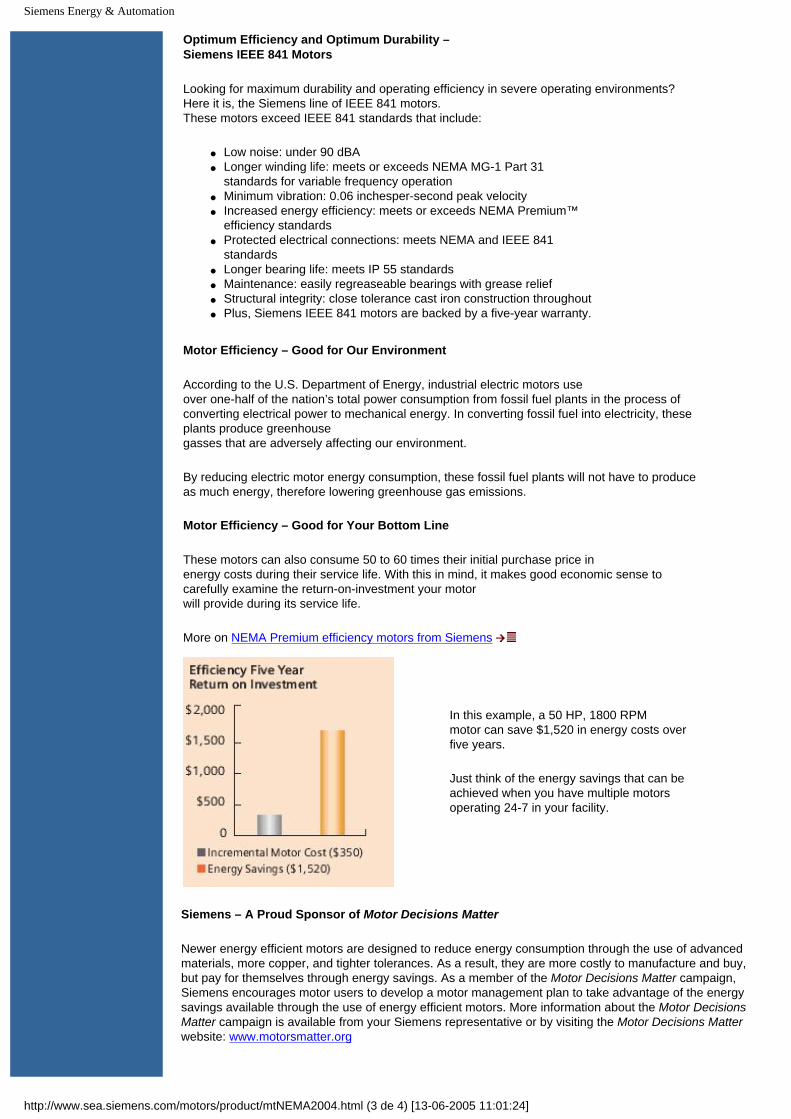
Siemens Energy & Automation
Optimum Efficiency and Optimum Durability –Siemens IEEE 841 Motors
Looking for maximum durability and operating efficiency in severe operating environments? Here it is, the Siemens line of IEEE 841 motors.These motors exceed IEEE 841 standards that include:
● Low noise: under 90 dBA● Longer winding life: meets or exceeds NEMA MG-1 Part 31
standards for variable frequency operation● Minimum vibration: 0.06 inchesper-second peak velocity● Increased energy efficiency: meets or exceeds NEMA Premium™
efficiency standards● Protected electrical connections: meets NEMA and IEEE 841
standards● Longer bearing life: meets IP 55 standards● Maintenance: easily regreaseable bearings with grease relief● Structural integrity: close tolerance cast iron construction throughout● Plus, Siemens IEEE 841 motors are backed by a five-year warranty.
Motor Efficiency – Good for Our Environment
According to the U.S. Department of Energy, industrial electric motors useover one-half of the nation’s total power consumption from fossil fuel plants in the process of converting electrical power to mechanical energy. In converting fossil fuel into electricity, these plants produce greenhousegasses that are adversely affecting our environment.
By reducing electric motor energy consumption, these fossil fuel plants will not have to produce as much energy, therefore lowering greenhouse gas emissions.
Motor Efficiency – Good for Your Bottom Line
These motors can also consume 50 to 60 times their initial purchase price inenergy costs during their service life. With this in mind, it makes good economic sense to carefully examine the return-on-investment your motorwill provide during its service life.
More on NEMA Premium efficiency motors from Siemens
In this example, a 50 HP, 1800 RPMmotor can save $1,520 in energy costs over five years.
Just think of the energy savings that can be achieved when you have multiple motors operating 24-7 in your facility.
Siemens – A Proud Sponsor of Motor Decisions Matter
Newer energy efficient motors are designed to reduce energy consumption through the use of advanced materials, more copper, and tighter tolerances. As a result, they are more costly to manufacture and buy, but pay for themselves through energy savings. As a member of the Motor Decisions Matter campaign, Siemens encourages motor users to develop a motor management plan to take advantage of the energy savings available through the use of energy efficient motors. More information about the Motor Decisions Matter campaign is available from your Siemens representative or by visiting the Motor Decisions Matter website: www.motorsmatter.org
http://www.sea.siemens.com/motors/product/mtNEMA2004.html (3 de 4) [13-06-2005 11:01:24]

Siemens Energy & Automation
Siemens Motors and Drives – Perfect Harmony
Performance-matched, variable-speed motors and drives from Siemens make perfect sense. They are designed to work together for faster selection, start-up, long-term reliability, and performance. Whether your application requires variable torque capability to operate pumps or fans, constant torque operation for conveyors, hoists or winches, or low-speed constant torque operation in hostile environments – there’s a Siemens motor and drive combination available for you. Siemens Drives Community Page
Siemens inverter duty motors meet IEEE and NEMA standards for variable frequency operation, and feature our unique NEMA Class F insulation system to virtually eliminate concerns about harmonic and corona damage.
©2005, Siemens Energy & Automation, Inc. Legal Notices / Privacy PolicyContact Us
http://www.sea.siemens.com/motors/product/mtNEMA2004.html (4 de 4) [13-06-2005 11:01:24]

Siemens AC Motors Main Page, USA
Contact Us
About Us Training Careers
Sales Offices News Support Search
Advanced Search
Energy &Automation Home Current Stock Quote: SI
Solutions CommunitiesAutomotiveCementChemicalFood & BeverageMachine ToolsMarineMESMetalsMiningOil & GasPharmaceuticalProduction MachinesPulp & PaperQualityOther Industries
Product CommunitiesAutomationCNCControlsDrivesElectric MotorsInstrumentation & AnalyticsMotion ControlPower DistributionProcess AutomationResidential Electrical
Services CommunitiesIndustrial ServicesIT Plant Services
LinksNEMA web siteKnowledge@EmorySiemens Racing
Electric Motor Products@Siemens
Siemens – More than Just a Motor Siemens offers the best value for your constant or variable-speed motor application. Siemens is the number one provider of motors worldwide, with global service and support second to none. Application support, availability, wide selection and uncompromising quality are ways we can help you receive optimum value for your motor investment. It’s an investment that pays off through reliable operation, energy savings and long service life – day after day, year after year.
NEMA Motors | Above NEMA Motors Success stories from Siemens
NEMA Premium
Motors Products & Services
NEMA motors Related products (MCCs, Controls, Drives, etc.)
Inverter Duty AC induction motors
Motor Services
Above NEMA motors
General motors information, including white papers and technical documents
Servo Motors
Quick DownloadsBrochures
Price Guides
Manuals & Instruction Guides
Dimension Prints
Motors & Industry NewsMotors & Industry News Archive
Product Information
SpeedFAX Catalog Industrial Controls
Catalog Product Reference Library
Technical Services
Locate your nearest office:
Enter Zip Code: Go
24hr Hotline:1-800-241-4453
Email Technical Services
Machine Tool Service
Online Customer ServiceSiemens Online Customer Service is a private source for order, product, and pricing information.
Distributor Locator
Training@SiemensTo view this in-line frame correctly, you'll need to use Internet Explorer. Please contact the the training registrar at 800.241.4453 or [email protected].
http://www.sea.siemens.com/motors/default.html (1 de 2) [13-06-2005 11:03:54]

Siemens AC Motors Main Page, USA
Bookmark This Page
Calendar of Events
June 26-29, 2005 EASA Convention Nashville, TN
©2005, Siemens Energy & Automation, Inc. Legal Notices / Privacy Policy Contact Us
http://www.sea.siemens.com/motors/default.html (2 de 2) [13-06-2005 11:03:54]

Application Manual for NEMA Motors
External Load Inertia Capability, Wk2 [lb-ft2]
SectionPartPageDate
54112/98
NOTES:1 Locked rotor and breakdown torques are per NEMA design A and B for general
purpose motors.2 Class F insulation with standard service factor and temperature rise.3 Rated voltage and frequency applied.4 During acceleration period, connected load torque varies as the square of the
speed and equal to rated torque at rated speed.5 Two consecutive cold starts or one start with motor at rated temperature.
MOTORHP
SYNCHRONOUS SPEED AND ENCLOSURE
3600 RPM 1800 RPM
ODP TEFC ODP TEFC
0.75 - - - -
1 - - 12 12
1.5 4.2 4.2 17 17
2 4.5 4.5 23 23
3 5 6.5 35 35
5 8 11 55 55
7.5 13 18 80 80
10 20 26 105 105
15 30 41 200 220
20 45 53 250 270
25 55 68 305 340
30 65 83 375 420
40 85 107 480 540
50 120 150 580 680
60 155 180 650 800
75 200 240 790 920
100 250 250 1000 1250
125 300 310 1260 1570
150 350 380 1450 1900
200 425 500 1850 2550
250 525 600 2280 3150
300 600 695 2750 3520
350 685 800 3410 4100
400 765 900 3900 4670
1200 RPM
ODP
20
24
45
60
85
145
230
310
460
610
770
920
1200
1520
1710
2150
2870
3480
4010
5100
6380
7310
-
-
900 RPM
TEFC ODP
20 46
24 60
45 90
60 115
87 180
150 300
240 430
350 540
530 820
750 1100
950 1350
1150 1580
1600 2100
1750 2890
1930 3460
2410 4300
3150 5570
3880 6790
4490 8140
5950 11250
7130 13570
8420 -
9900 -
- -
TEFC
47
63
95
150
240
400
600
730
1100
1400
1700
1990
2500
3020
3800
4700
6250
7800
9300
12400
15400
-
-
-
450 860 - - - - - - -

Application Manual for NEMA Motors
Insulation System600 Volts and LowerClass B and Class F
SectionPartPageDate
53112/98
Slot Liner: 100 % fill polyester fiber - polyester film - polyester fiber laminate (DMD).
Magnet Wire: Round random wound cooper conducters with heavy terephthalic polyetsercoating and Amide-Imide overcoat (200˚C).
Coil Separator: 100% fill polyester fiber - polyester film - polyester fiber laminate (DMD).
Slot Wedges: Formed aromatic polyamide or 100% treated polyester fiber - polyester film -polyester fiber or polyester glass laminate.
Sleeving: Acrylic coated glass sleeving impregnated with varnish or aromatic polyamide -polyester film sleeving.
Tie Cord: Heat shrinkable polyester.
Phase Insulation: 100% fill polyester fiber - polyester film - polyester fiber laminate or varnishedglass cloth.
Varnish: 100% solids polyester resin.
Leads: Cross linked polymeric or Teflon.
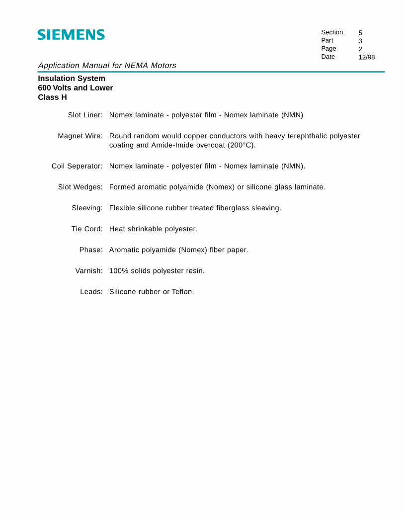
Application Manual for NEMA Motors
Insulation System600 Volts and LowerClass H
SectionPartPageDate
53212/98
Slot Liner: Nomex laminate - polyester film - Nomex laminate (NMN)
Magnet Wire: Round random would copper conductors with heavy terephthalic polyestercoating and Amide-Imide overcoat (200°C).
Coil Seperator: Nomex laminate - polyester film - Nomex laminate (NMN).
Slot Wedges: Formed aromatic polyamide (Nomex) or silicone glass laminate.
Sleeving: Flexible silicone rubber treated fiberglass sleeving.
Tie Cord: Heat shrinkable polyester.
Phase: Aromatic polyamide (Nomex) fiber paper.
Varnish: 100% solids polyester resin.
Leads: Silicone rubber or Teflon.
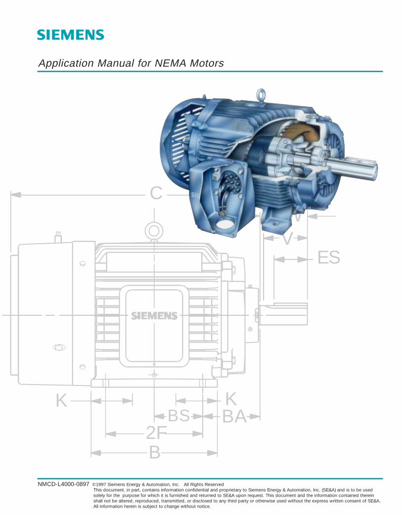
C
ES
N-W
B2F
BS BAKK
V
Application Manual for NEMA Motors
NMCD-L4000-0897 ©1997 Siemens Energy & Automation, Inc. All Rights ReservedThis document, in part, contains information confidential and proprietary to Siemens Energy & Automation, Inc. (SE&A) and is to be usedsolely for the purpose for which it is furnished and returned to SE&A upon request. This document and the information contained thereinshall not be altered, reproduced, transmitted, or disclosed to any third party or otherwise used without the express written consent of SE&A.All information herein is subject to change without notice.

NEMA Frames Application Manual
Table of Contents
Page DateSection 1 Index of Products
1 Product Range and Scope 1 6/972 Construction Features 1 6/973 Motor Type Designations 1 6/97
Section 2 Basic Motor Terminology and Theory1 Motor Terminology 1-4 6/972 Basic Noise Theory 1-6 6/973 Effect of Power Supply Variations 7 6/97
Section 3 Descriptive Material 1 6/97
Section 4 Dimensional Drawings
Horizontal Motors1 Slide Bases 1-5 6/972 Open Drip-proof 1-14 6/973 Totally Enclosed Fan Cooled 1-31 6/974 Severe Duty 1-39 6/975 Explosion-proof 1-24 6/97
Vertical Motors6 Totally Enclosed Fan Cooled 1-16 6/976 Hollow Shaft 17-19 6/977 Severe Duty 1-27 6/978 Explosion-proof 1-27 6/97
Section 5 Electrical Data1 Frame Assignments 1-5 6/972 Speed Torque Curves 1-91 6/973 Insulation System 1-2 6/974 External Load WK2 Capabilities 1-4 6/975 Connection Diagrams 1-4 6/976 Temperature Rise 1 6/97

Application Manual for NEMA Motors
Table of Contents
Page DateSection 6 Mechanical Data
1 Conduit Boxes 1-3 6/972 Standard Rotor Balance 1-2 6/973 Standard Shaft Material 1 6/974 Motor Bearing Sizes 1-6 6/975 Belted Service 1 6/976 Rotor Weight and WK2 1-5 6/977 Paint Standard 1 6/978 Packaging 1 6/979 Noise Data 6/97
10 Modifications for Low Temperature 1 6/97
Section 7 Accessories1 Space Heaters 1-2 6/972 Thermal Protective Devices 1-2 6/97
Section 8 Standards1 National Electrical Manufactures Association 1-2 6/972 The Institute of Electrical and Electronic Engineers 1-2 6/973 American Petroleum Institute 1 6/974 Hazardous Location Classifications and
Underwriters Laboratory 1-7 6/975 Canadian Standards Association 1-2 6/976 Standards Agencies’ Addresses 1-7 6/977 CE Mark 1-2 6/97
Section 9 Tests1 Standard Commercial Test 1 6/972 Complete Test 1 6/973 Noise Test 1 6/97
Section 10 Special Applications and Information1 Power Factor Correction 1-4 6/972 Methods of Starting 3 Phase Motors 1-14 6/973 Duty Cycles and Inertia 1-7 6/974 Horsepower Determination 1 6/975 General Formulas 1-3 6/97

NEMA Frames Application Manual
Tests
SectionPartPageDate
90Index6/97
Page DatePart 1 Standard Commercial Tests 1 6/97
Part 2 Complete Tests 1 6/97
Part 3 Noise Tests 1 6/97

Application Manual for NEMA Motors
Standard Commercial Test
SectionPartPageDate
91112/98
Standard Commercial Tests per IEEE 112 are performed on all motors and include the following tests:
1. No-load readings of current at rated voltage and frequency.For 50 Hz motors, these readings may be taken at 60 Hz.
2. Check excessive vibration and bearing noise.
3. Measurement of winding resistance at room temperature.
4. Dielectric test - AC voltage of 2304 is applied for one second. (460 v. Motors)
5. Measurement of single phase locked rotor current at one-fourth the rated voltage.
6. Thermostats (klixons) are checked for continuity of circuit.
7. Space heaters wattage is measured with rated voltage applied across heater terminals.
Test reports are made only when specified on the order.

Application Manual for NEMA Motors
Complete Tests
SectionPartPageDate
921
12/98
Complete tests are performed only when specified and include the following:
1. Winding resistance is measured at room temperature.
2. Motor is run no-load at rated voltage with current and watts measured.
3. Full-load heat run includes the following readings and measurements.a. Currents and voltages in all phases with amp meter and volt meter.b. Input watts with watt meter.c. Full-load speed is measured.d. Thermocouple temperatures are measured in the following locations:
- Yoke- Winding- Rear bearing hub- Ambient air
e. Efficiency is determined by dynamometer per IEEE 112 (MG1-12.58.1).f. Power factor is calculated.g. Winding resistance is measured immediately after shutdown.
4. Dielectric test - AC voltage applied at 2304 volts for 1 second. (460 v. Motors)
5. Locked rotor current and torque are measured.
6. Breakdown torque is measured.
7. Check for excessive vibration and bearing noise.
8. Thermostats (klixons) are checked for circuit continuity.
9. Space heater ratings are verified.
10. Test reports are submitted.

Application Manual for NEMA Motors
Noise Tests
SectionPartPageDate
93112/98
Noise tests are coinducted per IEEE No. 85 - “Test Procedure for Airborne Sound Measurements on Rotating Electric Machinery” using a microphone in a test environment of a free field over areflecting plane.
Test measurements recorded are overall and 7 octave levels of sound pressure readings at 11prescribed points plus ambient at overall and 7 octave levels.
Overall A-weighted Sound Power and Sound Pressure at a reference distance of 1 meter arecomputed from data recorded.
All noise tests are performed at the Little Rock Plant.
Accuracy is within a ±3 dB.

Siemens Energy & Automation
Siemens 2005 Contractor's Edge Program
Siemens 2005 Contractor Advantage Rewards Program
Siemens 2004 Contractor Council Siemens Carolina Residential Contractor CouncilKey local contractors from the North and South Carolina area attended a dinner and trade show hosted by Residential Marketing and the Carolinas Sales Team. They provided valuable input on ways to improve existing products, participated in a preview session to discuss new products and exchange information on market conditions. These events will continue throughout the year to solicit valuable feedback and reinforce business relationships with the market place.
Image at the left: Siemens Product Manager, Jon Pickens (right), discusses Siemens products with a contractor and Sales Manager, Rick Brooks (center).
Image at the left: Market Development Manager, Kirk Brown (center), explains the features and benefits of using Siemens products.
Builder's Circle Program
Siemens 2004 Drive To Rewards Program Winners
Residential Electrical Product Information AC Disconnects Circuit Breakers Load Centers Meter Combinations & Meter Mains
Meter Sockets Multi-Family Metering Power Outlet Panels Surge Protection
http://www.sea.siemens.com/reselec/default.html [13-06-2005 11:06:21]