sight flow indicators - tom parker ltd · rhodes sight flow indicators are found in process, ......
TRANSCRIPT
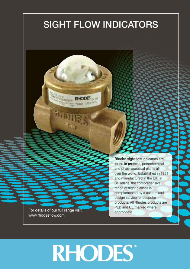
Rhodes sight flow indicators arefound in process, petrochemicaland pharmaceutical plants all over the world. Established in 1951and manufactured in the UK, in St Helens, the comprehensiverange of sight glasses iscomplemented by a customiseddesign service for bespokeproducts. All Rhodes products arePED and CE marked whereappropriate.
SIGHT FLOW INDICATORS
For details of our full range visitwww.rhodesflow.com
Technical Helpline: 01744 453688E: [email protected] W: www.rhodesflow.com
72
SIGHT FLOW INDICATORS / 233 SERIES 234 SERIES
Every effort has been made to ensure that the information contained in this publication is accurate at the time of publishing. Crane Ltd assumes no responsibility orliability for typographical errors or omissions or for any misinterpretation of the information within the publication and reserves the right to change without notice.
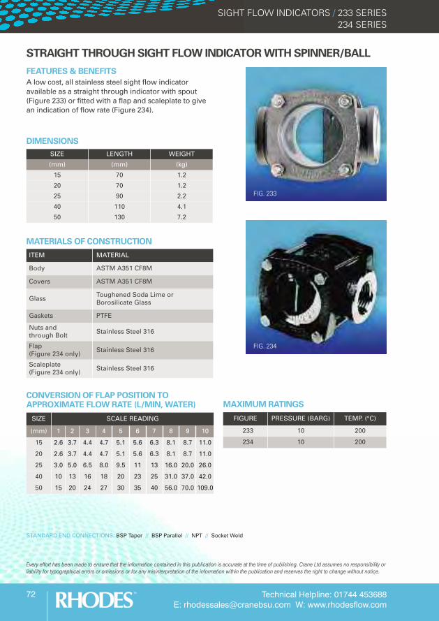
FIG. 233
ITEM MATERIAL
Body ASTM A351 CF8M
Covers ASTM A351 CF8M
Glass Toughened Soda Lime or Borosilicate Glass
Gaskets PTFE
Nuts and through Bolt Stainless Steel 316
Flap (Figure 234 only) Stainless Steel 316
Scaleplate (Figure 234 only) Stainless Steel 316
MATERIALS OF CONSTRUCTION
STANDARD END CONNECTIONS: BSP Taper // BSP Parallel // NPT // Socket Weld
STRAIGHT THROUGH SIGHT FLOW INDICATOR WITH SPINNER/BALL
FEATURES & BENEFITSA low cost, all stainless steel sight flow indicatoravailable as a straight through indicator with spout(Figure 233) or fitted with a flap and scaleplate to givean indication of flow rate (Figure 234).
SIZE LENGTH WEIGHT
(mm) (mm) (kg)
15 70 1.2
20 70 1.2
25 90 2.2
40 110 4.1
50 130 7.2
FIGURE PRESSURE (BARG) TEMP. (°C)
233 10 200
234 10 200
DIMENSIONS
FIG. 234
SIZE SCALE READING
(mm) 1 2 3 4 5 6 7 8 9 10
15 2.6 3.7 4.4 4.7 5.1 5.6 6.3 8.1 8.7 11.0
20 2.6 3.7 4.4 4.7 5.1 5.6 6.3 8.1 8.7 11.0
25 3.0 5.0 6.5 8.0 9.5 11 13 16.0 20.0 26.0
40 10 13 16 18 20 23 25 31.0 37.0 42.0
50 15 20 24 27 30 35 40 56.0 70.0 109.0
MAXIMUM RATINGSCONVERSION OF FLAP POSITION TOAPPROXIMATE FLOW RATE (L/MIN, WATER)
Technical Helpline: 01744 453688E: [email protected] W: www.rhodesflow.com
73
SIGHT FLOW INDICATORS / 400 SERIES400B SERIES
Every effort has been made to ensure that the information contained in this publication is accurate at the time of publishing. Crane Ltd assumes no responsibility orliability for typographical errors or omissions or for any misinterpretation of the information within the publication and reserves the right to change without notice.
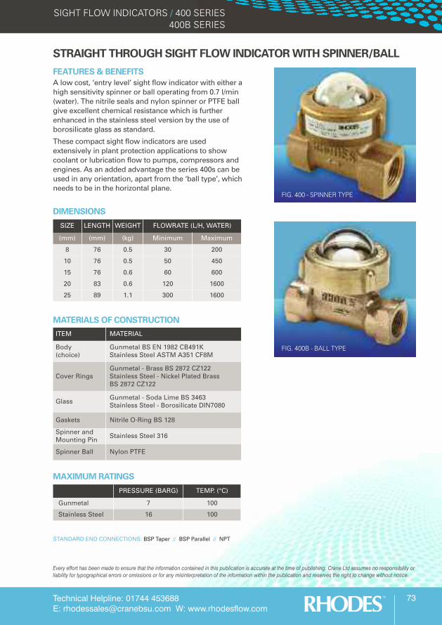
FIG. 400 - SPINNER TYPE
ITEM MATERIAL
Body (choice)
Gunmetal BS EN 1982 CB491KStainless Steel ASTM A351 CF8M
Cover RingsGunmetal - Brass BS 2872 CZ122Stainless Steel - Nickel Plated Brass BS 2872 CZ122
Glass Gunmetal - Soda Lime BS 3463Stainless Steel - Borosilicate DIN7080
Gaskets Nitrile O-Ring BS 128
Spinner and Mounting Pin Stainless Steel 316
Spinner Ball Nylon PTFE
MATERIALS OF CONSTRUCTION
MAXIMUM RATINGS
STANDARD END CONNECTIONS: BSP Taper // BSP Parallel // NPT
STRAIGHT THROUGH SIGHT FLOW INDICATOR WITH SPINNER/BALL
FEATURES & BENEFITSA low cost, ‘entry level’ sight flow indicator with either ahigh sensitivity spinner or ball operating from 0.7 l/min(water). The nitrile seals and nylon spinner or PTFE ballgive excellent chemical resistance which is furtherenhanced in the stainless steel version by the use ofborosilicate glass as standard.
These compact sight flow indicators are usedextensively in plant protection applications to showcoolant or lubrication flow to pumps, compressors andengines. As an added advantage the series 400s can beused in any orientation, apart from the ‘ball type’, whichneeds to be in the horizontal plane.
SIZE LENGTH WEIGHT FLOWRATE (L/H, WATER)
(mm) (mm) (kg) Minimum Maximum
8 76 0.5 30 200
10 76 0.5 50 450
15 76 0.6 60 600
20 83 0.6 120 1600
25 89 1.1 300 1600
PRESSURE (BARG) TEMP. (°C)
Gunmetal 7 100
Stainless Steel 16 100
DIMENSIONS
FIG. 400B - BALL TYPE
Technical Helpline: 01744 453688E: [email protected] W: www.rhodesflow.com
74
SIGHT FLOW INDICATORS / 408 SERIES
Every effort has been made to ensure that the information contained in this publication is accurate at the time of publishing. Crane Ltd assumes no responsibility orliability for typographical errors or omissions or for any misinterpretation of the information within the publication and reserves the right to change without notice.
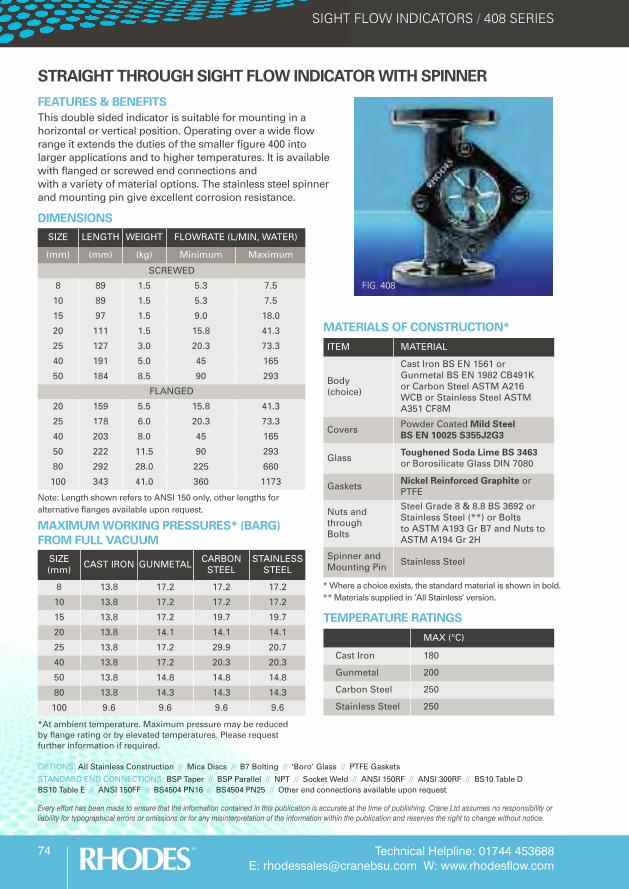
FIG. 408
SIZE LENGTH WEIGHT FLOWRATE (L/MIN, WATER)
(mm) (mm) (kg) Minimum Maximum
SCREWED
8 89 1.5 5.3 7.5
10 89 1.5 5.3 7.5
15 97 1.5 9.0 18.0
20 111 1.5 15.8 41.3
25 127 3.0 20.3 73.3
40 191 5.0 45 165
50 184 8.5 90 293
FLANGED
20 159 5.5 15.8 41.3
25 178 6.0 20.3 73.3
40 203 8.0 45 165
50 222 11.5 90 293
80 292 28.0 225 660
100 343 41.0 360 1173
Note: Length shown refers to ANSI 150 only, other lengths foralternative flanges available upon request.
*At ambient temperature. Maximum pressure may be reducedby flange rating or by elevated temperatures. Please requestfurther information if required.
SIZE (mm) CAST IRON GUNMETAL CARBON
STEELSTAINLESS
STEEL
8 13.8 17.2 17.2 17.2
10 13.8 17.2 17.2 17.2
15 13.8 17.2 19.7 19.7
20 13.8 14.1 14.1 14.1
25 13.8 17.2 29.9 20.7
40 13.8 17.2 20.3 20.3
50 13.8 14.8 14.8 14.8
80 13.8 14.3 14.3 14.3
100 9.6 9.6 9.6 9.6
MAXIMUM WORKING PRESSURES* (BARG)FROM FULL VACUUM
ITEM MATERIAL
Body (choice)
Cast Iron BS EN 1561 or Gunmetal BS EN 1982 CB491K or Carbon Steel ASTM A216 WCB or Stainless Steel ASTM A351 CF8M
Covers Powder Coated Mild Steel BS EN 10025 S355J2G3
Glass Toughened Soda Lime BS 3463 or Borosilicate Glass DIN 7080
Gaskets Nickel Reinforced Graphite or PTFE
Nuts and through Bolts
Steel Grade 8 & 8.8 BS 3692 or Stainless Steel (**) or Bolts to ASTM A193 Gr B7 and Nuts to ASTM A194 Gr 2H
Spinner and Mounting Pin Stainless Steel
MATERIALS OF CONSTRUCTION*
MAX (°C)
Cast Iron 180
Gunmetal 200
Carbon Steel 250
Stainless Steel 250
TEMPERATURE RATINGS
OPTIONS: All Stainless Construction // Mica Discs // B7 Bolting // ‘Boro’ Glass // PTFE Gaskets
STANDARD END CONNECTIONS: BSP Taper // BSP Parallel // NPT // Socket Weld // ANSI 150RF // ANSI 300RF // BS10 Table DBS10 Table E // ANSI 150FF // BS4504 PN16 // BS4504 PN25 // Other end connections available upon request
STRAIGHT THROUGH SIGHT FLOW INDICATOR WITH SPINNER
FEATURES & BENEFITSThis double sided indicator is suitable for mounting in ahorizontal or vertical position. Operating over a wide flowrange it extends the duties of the smaller figure 400 intolarger applications and to higher temperatures. It is availablewith flanged or screwed end connections and with a variety of material options. The stainless steel spinnerand mounting pin give excellent corrosion resistance.
* Where a choice exists, the standard material is shown in bold.** Materials supplied in ‘All Stainless’ version.
DIMENSIONS
Technical Helpline: 01744 453688E: [email protected] W: www.rhodesflow.com
75
SIGHT FLOW INDICATORS / 901 SERIES902 SERIES
Every effort has been made to ensure that the information contained in this publication is accurate at the time of publishing. Crane Ltd assumes no responsibility orliability for typographical errors or omissions or for any misinterpretation of the information within the publication and reserves the right to change without notice.
ITEM MATERIAL
Body Gunmetal BS EN 1982 CB491K
Covers Mild Steel BS EN 10025 S355J2G3
Flow Fingers Glass Filled Nylon
Glass Toughened Soda Lime BS 3463or Borosilicate Glass DIN 7080
Gaskets Nickel Reinforced Graphite or PTFE
Fasteners Steel Grade 8 & 8.8 BS 3692
MATERIALS OF CONSTRUCTION
MAXIMUM RATINGS
STRAIGHT THROUGH SIGHT FLOW INDICATORS - GUNMETAL
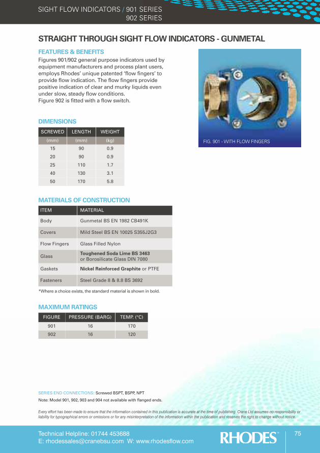
FEATURES & BENEFITSFigures 901/902 general purpose indicators used byequipment manufacturers and process plant users,employs Rhodes’ unique patented ‘flow fingers’ toprovide flow indication. The flow fingers providepositive indication of clear and murky liquids evenunder slow, steady flow conditions. Figure 902 is fitted with a flow switch.
SCREWED LENGTH WEIGHT
(mm) (mm) (kg)
15 90 0.9
20 90 0.9
25 110 1.7
40 130 3.1
50 170 5.8
FIGURE PRESSURE (BARG) TEMP. (°C)
901 16 170
902 16 120
DIMENSIONS
SERIES END CONNECTIONS: Screwed BSPT, BSPP, NPT
Note: Model 901, 902, 903 and 904 not available with flanged ends.
FIG. 901 - WITH FLOW FINGERS
*Where a choice exists, the standard material is shown in bold.

Technical Helpline: 01744 453688E: [email protected] W: www.rhodesflow.com
76
SIGHT FLOW INDICATORS / 903 SERIES904 SERIES
Every effort has been made to ensure that the information contained in this publication is accurate at the time of publishing. Crane Ltd assumes no responsibility orliability for typographical errors or omissions or for any misinterpretation of the information within the publication and reserves the right to change without notice.
SIZE SCALE READING ON 904
(mm) 1 2 3 4 5 6 7 8 9 10
15/20 3 4 5 7 8 9 10 14 20 25
25 5 7 9 10 13 15 18 21 28 40
40 10 14 19 22 27 30 36 44 63 76
50 15 23 29 35 41 40 59 79 118 195
SERIES END CONNECTIONS: Screwed BSPT, BSPP, NPT
Note: Model 901, 902, 903 and 904 not available with flanged ends.
ITEM MATERIAL
Flap 316 Stainless Steel
Scaleplate 316 Stainless Steel
MATERIALS OF CONSTRUCTION - 904As the 903 but with:
STRAIGHT THROUGH SIGHT FLOW INDICATORS - GUNMETAL
FEATURES & BENEFITSThe Figure 903 series is a two-sided flow indicatorfeaturing an integral spout that produces a jetting actionfor turbulent flow, thereby improving the viewing of clearliquids. The large viewing area allows the flow, colour andcondition of the liquid to be observed and hence provides acheck on product quality and consistency. It is suitable forboth vertical and horizontal installation. The inclusion of aspout allows it to be used as a drip indicator to show valveleaks, distillation or similar conditions.
The Figure 904 series incorporates a pivoted internal flap,which, by its position in relation to a graduated scaleplate,indicates any changes in the rate of flow of a liquid in apipeline, from a trickle to full flow conditions. The internalstainless steel flap is electropolished to improve viewing inmurky liquids. This series is suitable for both horizontaland vertical upward flows. A variety of materials areavailable as standard.
SCREWED LENGTH WEIGHT
(mm) (mm) (kg)
15 90 0.9
20 90 0.9
25 110 1.7
40 130 3.1
50 170 5.8
DIMENSIONS
FIG. 903 - WITH INTEGRAL SPOUT
FIG. 904 - WITH FLAP & SCALEPLATE
ITEM MATERIAL
Body Gunmetal BS EN 1982 CB491K
Covers Mild Steel BS EN 10025 S355J2G3
Glass Toughened Soda Lime BS 3463or Borosilicate Glass DIN 7080
Gaskets Nickel Reinforced Graphite or PTFE
Fasteners Steel Grade 8 & 8.8 BS 3692
MATERIALS OF CONSTRUCTION - 903
FLOW INFORMATION (L/MIN, WATER)
MAXIMUM RATINGS
FIGURE PRESSURE (BARG) TEMP. (°C)
903 16 200
904 16 200
Technical Helpline: 01744 453688E: [email protected] W: www.rhodesflow.com
77
SIGHT FLOW INDICATORS / 913 SERIES
Every effort has been made to ensure that the information contained in this publication is accurate at the time of publishing. Crane Ltd assumes no responsibility orliability for typographical errors or omissions or for any misinterpretation of the information within the publication and reserves the right to change without notice.
STRAIGHT THROUGH SIGHT FLOW INDICATORS - CAST IRON
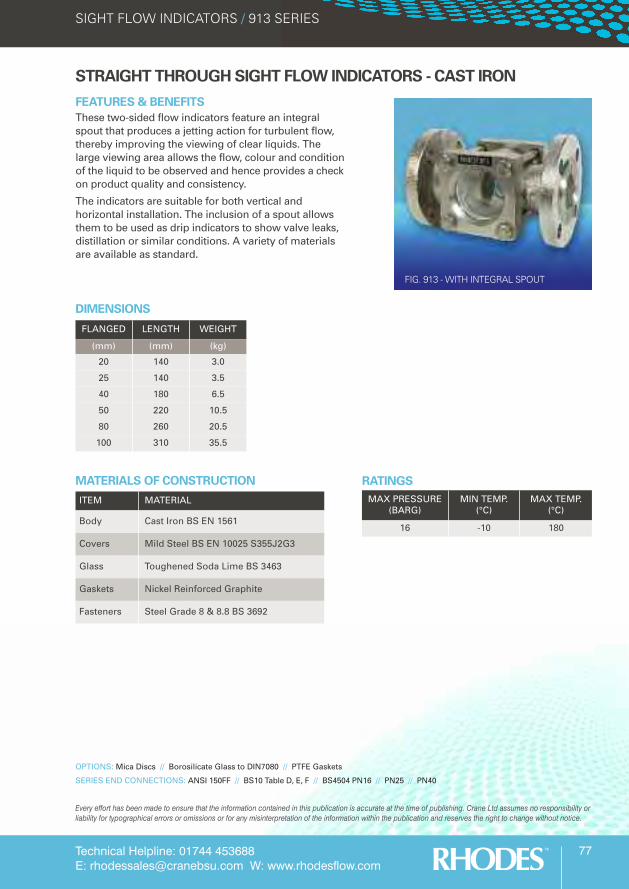
FEATURES & BENEFITSThese two-sided flow indicators feature an integralspout that produces a jetting action for turbulent flow,thereby improving the viewing of clear liquids. Thelarge viewing area allows the flow, colour and conditionof the liquid to be observed and hence provides a checkon product quality and consistency.
The indicators are suitable for both vertical andhorizontal installation. The inclusion of a spout allowsthem to be used as drip indicators to show valve leaks,distillation or similar conditions. A variety of materialsare available as standard.
FLANGED LENGTH WEIGHT
(mm) (mm) (kg)
20 140 3.0
25 140 3.5
40 180 6.5
50 220 10.5
80 260 20.5
100 310 35.5
DIMENSIONS
ITEM MATERIAL
Body Cast Iron BS EN 1561
Covers Mild Steel BS EN 10025 S355J2G3
Glass Toughened Soda Lime BS 3463
Gaskets Nickel Reinforced Graphite
Fasteners Steel Grade 8 & 8.8 BS 3692
MATERIALS OF CONSTRUCTION
OPTIONS: Mica Discs // Borosilicate Glass to DIN7080 // PTFE Gaskets
SERIES END CONNECTIONS: ANSI 150FF // BS10 Table D, E, F // BS4504 PN16 // PN25 // PN40
RATINGSMAX PRESSURE
(BARG)MIN TEMP.
(°C)MAX TEMP.
(°C)
16 -10 180
FIG. 913 - WITH INTEGRAL SPOUT
Technical Helpline: 01744 453688E: [email protected] W: www.rhodesflow.com
78
SIGHT FLOW INDICATORS / 914 SERIES
Every effort has been made to ensure that the information contained in this publication is accurate at the time of publishing. Crane Ltd assumes no responsibility orliability for typographical errors or omissions or for any misinterpretation of the information within the publication and reserves the right to change without notice.
RATINGSMAX PRESSURE
(BARG)MIN TEMP.
(°C)MAX TEMP.
(°C)
16 -10 180
STRAIGHT THROUGH SIGHT FLOW INDICATORS - CAST IRON
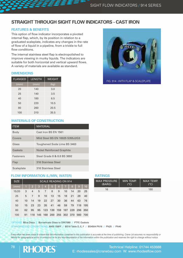
FEATURES & BENEFITSThis option of flow indicator incorporates a pivotedinternal flap, which, by its position in relation to agraduated scaleplate, indicates any changes in the rateof flow of a liquid in a pipeline, from a trickle to fullflow conditions.
The internal stainless steel flap is electropolished toimprove viewing in murky liquids. The indicators aresuitable for both horizontal and vertical upward flows.A variety of materials are available as standard.
FLANGED LENGTH WEIGHT
(mm) (mm) (kg)
20 140 3.0
25 140 3.5
40 180 6.5
50 220 10.5
80 260 20.5
100 310 35.5
DIMENSIONS
ITEM MATERIAL
Body Cast Iron BS EN 1561
Covers Mild Steel BS EN 10025 S355J2G3
Glass Toughened Soda Lime BS 3463
Gaskets Nickel Reinforced Graphite
Fasteners Steel Grade 8 & 8.8 BS 3692
Flap 316 Stainless Steel
Scaleplate 316 Stainless Steel
MATERIALS OF CONSTRUCTION
OPTIONS: Mica Discs // Borosilicate Glass to DIN7080 // PTFE Gaskets
STANDARD END CONNECTIONS: ANSI 150FF // BS10 Table D, E, F // BS4504 PN16 // PN25 // PN40
FLOW INFORMATION (L/MIN, WATER)
SIZE SCALE READING ON 914
(mm) 1 2 3 4 5 6 7 8 9 10
15/20 3 4 5 7 8 9 10 14 20 25
25 5 7 9 10 13 15 18 21 28 40
40 10 14 19 22 27 30 36 44 63 76
50 15 23 23 35 41 46 59 79 118 195
80 82 95 95 123 139 159 187 229 296 350
100 91 118 145 168 200 255 302 370 560 700
FIG. 914 - WITH FLAP & SCALEPLATE
Technical Helpline: 01744 453688E: [email protected] W: www.rhodesflow.com
79
SIGHT FLOW INDICATORS / 923 SERIES
Every effort has been made to ensure that the information contained in this publication is accurate at the time of publishing. Crane Ltd assumes no responsibility orliability for typographical errors or omissions or for any misinterpretation of the information within the publication and reserves the right to change without notice.
STRAIGHT THROUGH SIGHT FLOW INDICATORS - CARBON STEEL
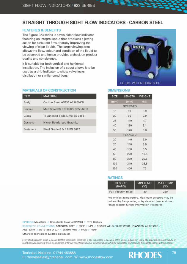
FEATURES & BENEFITSThe Figure 923 series is a two-sided flow indicatorfeaturing an integral spout that produces a jettingaction for turbulent flow, thereby improving theviewing of clear liquids. The large viewing areaallows the flow, colour and condition of the liquid tobe observed and hence provides a check on productquality and consistency.
It is suitable for both vertical and horizontalinstallation. The inclusion of a spout allows it to beused as a drip indicator to show valve leaks,distillation or similar conditions.
SIZE LENGTH WEIGHT
(mm) (mm) (kg)
SCREWED
15 90 0.9
20 90 0.9
25 110 1.7
40 130 3.1
50 170 5.8
FLANGED
20 140 3.0
25 140 3.5
40 180 6.5
50 220 10.5
80 260 20.5
100 310 35.5
150 406 76
DIMENSIONS
ITEM MATERIAL
Body Carbon Steel ASTM A216 WCB
Covers Mild Steel BS EN 10025 S355J2G3
Glass Toughened Soda Lime BS 3463
Gaskets Nickel Reinforced Graphite
Fasteners Steel Grade 8 & 8.8 BS 3692
MATERIALS OF CONSTRUCTION
OPTIONS: Mica Discs // Borosilicate Glass to DIN7080 // PTFE Gaskets
SERIES END CONNECTIONS: SCREWED: BSPT // BSPP // NPT // SOCKET WELD // BUTT WELD FLANGED: ANSI 150RF //ANSI 300RF // BS10 Table D, E, F // BS4504 PN16 // PN25 // PN40
Other end connections available on request.
RATINGSPRESSURE
(BARG)MIN TEMP.
(°C)MAX TEMP.
(°C)
Full Vacuum to 25 -30 250
*At ambient temperature. Maximum pressure may bereduced by flange rating or by elevated temperatures.Please request further information if required.
FIG. 923 - WITH INTEGRAL SPOUT
Technical Helpline: 01744 453688E: [email protected] W: www.rhodesflow.com
80
SIGHT FLOW INDICATORS / 924 SERIES
Every effort has been made to ensure that the information contained in this publication is accurate at the time of publishing. Crane Ltd assumes no responsibility orliability for typographical errors or omissions or for any misinterpretation of the information within the publication and reserves the right to change without notice.
STRAIGHT THROUGH SIGHT FLOW INDICATORS - CARBON STEEL
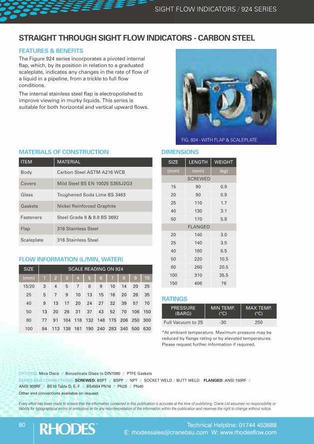
FEATURES & BENEFITSThe Figure 924 series incorporates a pivoted internalflap, which, by its position in relation to a graduatedscaleplate, indicates any changes in the rate of flow ofa liquid in a pipeline, from a trickle to full flowconditions.
The internal stainless steel flap is electropolished toimprove viewing in murky liquids. This series issuitable for both horizontal and vertical upward flows.
SIZE LENGTH WEIGHT
(mm) (mm) (kg)
SCREWED
15 90 0.9
20 90 0.9
25 110 1.7
40 130 3.1
50 170 5.8
FLANGED
20 140 3.0
25 140 3.5
40 180 6.5
50 220 10.5
80 260 20.5
100 310 35.5
150 406 76
DIMENSIONS
ITEM MATERIAL
Body Carbon Steel ASTM A216 WCB
Covers Mild Steel BS EN 10025 S355J2G3
Glass Toughened Soda Lime BS 3463
Gaskets Nickel Reinforced Graphite
Fasteners Steel Grade 8 & 8.8 BS 3692
Flap 316 Stainless Steel
Scaleplate 316 Stainless Steel
MATERIALS OF CONSTRUCTION
OPTIONS: Mica Discs // Borosilicate Glass to DIN7080 // PTFE Gaskets
SERIES END CONNECTIONS: SCREWED: BSPT // BSPP // NPT // SOCKET WELD // BUTT WELD FLANGED: ANSI 150RF //ANSI 300RF // BS10 Table D, E, F // BS4504 PN16 // PN25 // PN40
Other end connections available on request.
RATINGSPRESSURE
(BARG)MIN TEMP.
(°C)MAX TEMP.
(°C)
Full Vacuum to 25 -30 250
*At ambient temperature. Maximum pressure may bereduced by flange rating or by elevated temperatures.Please request further information if required.
FLOW INFORMATION (L/MIN, WATER)
SIZE SCALE READING ON 924
(mm) 1 2 3 4 5 6 7 8 9 10
15/20 3 4 5 7 8 9 10 14 20 25
25 5 7 9 10 13 15 16 20 26 35
40 9 13 17 20 24 27 32 39 57 70
50 13 20 26 31 37 43 52 70 106 150
80 77 91 104 118 132 148 175 206 250 300
100 84 113 138 161 190 240 283 340 500 630
FIG. 924 - WITH FLAP & SCALEPLATE
Technical Helpline: 01744 453688E: [email protected] W: www.rhodesflow.com
81
SIGHT FLOW INDICATORS / 933 SERIES
Every effort has been made to ensure that the information contained in this publication is accurate at the time of publishing. Crane Ltd assumes no responsibility orliability for typographical errors or omissions or for any misinterpretation of the information within the publication and reserves the right to change without notice.
STRAIGHT THROUGH SIGHT FLOW INDICATORS - STAINLESS STEEL
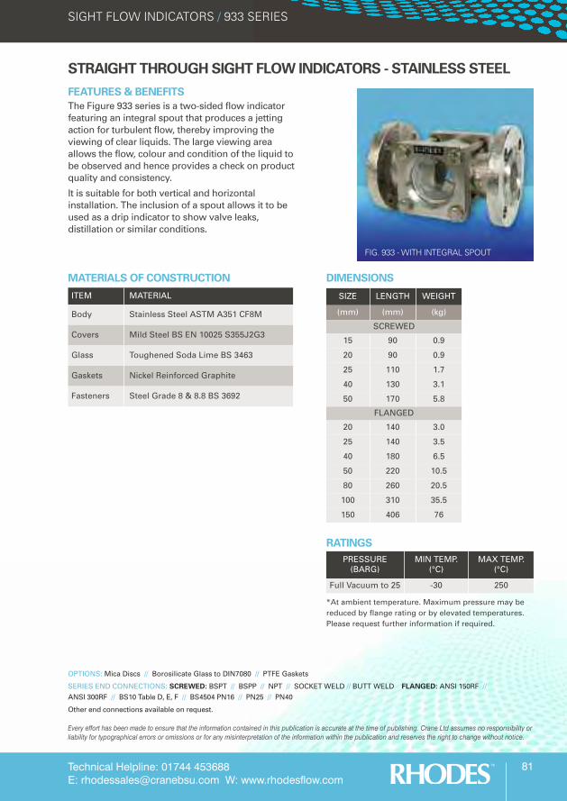
FEATURES & BENEFITSThe Figure 933 series is a two-sided flow indicatorfeaturing an integral spout that produces a jettingaction for turbulent flow, thereby improving theviewing of clear liquids. The large viewing areaallows the flow, colour and condition of the liquid tobe observed and hence provides a check on productquality and consistency.
It is suitable for both vertical and horizontalinstallation. The inclusion of a spout allows it to beused as a drip indicator to show valve leaks,distillation or similar conditions.
SIZE LENGTH WEIGHT
(mm) (mm) (kg)
SCREWED
15 90 0.9
20 90 0.9
25 110 1.7
40 130 3.1
50 170 5.8
FLANGED
20 140 3.0
25 140 3.5
40 180 6.5
50 220 10.5
80 260 20.5
100 310 35.5
150 406 76
DIMENSIONS
ITEM MATERIAL
Body Stainless Steel ASTM A351 CF8M
Covers Mild Steel BS EN 10025 S355J2G3
Glass Toughened Soda Lime BS 3463
Gaskets Nickel Reinforced Graphite
Fasteners Steel Grade 8 & 8.8 BS 3692
MATERIALS OF CONSTRUCTION
OPTIONS: Mica Discs // Borosilicate Glass to DIN7080 // PTFE Gaskets
SERIES END CONNECTIONS: SCREWED: BSPT // BSPP // NPT // SOCKET WELD // BUTT WELD FLANGED: ANSI 150RF //ANSI 300RF // BS10 Table D, E, F // BS4504 PN16 // PN25 // PN40
Other end connections available on request.
RATINGSPRESSURE
(BARG)MIN TEMP.
(°C)MAX TEMP.
(°C)
Full Vacuum to 25 -30 250
*At ambient temperature. Maximum pressure may bereduced by flange rating or by elevated temperatures.Please request further information if required.
FIG. 933 - WITH INTEGRAL SPOUT
Technical Helpline: 01744 453688E: [email protected] W: www.rhodesflow.com
82
SIGHT FLOW INDICATORS / 934 SERIES
Every effort has been made to ensure that the information contained in this publication is accurate at the time of publishing. Crane Ltd assumes no responsibility orliability for typographical errors or omissions or for any misinterpretation of the information within the publication and reserves the right to change without notice.
STRAIGHT THROUGH SIGHT FLOW INDICATORS - STAINLESS STEEL
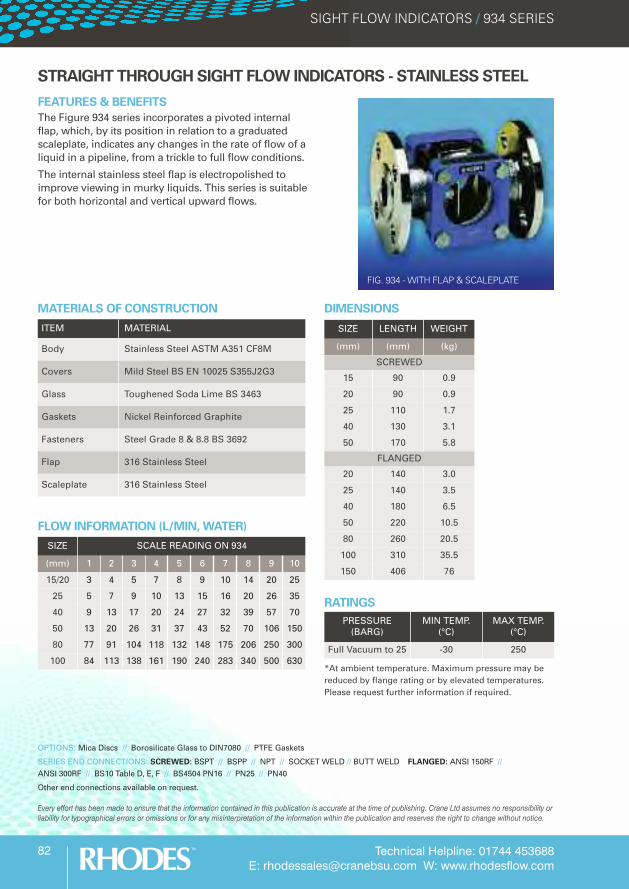
FEATURES & BENEFITSThe Figure 934 series incorporates a pivoted internalflap, which, by its position in relation to a graduatedscaleplate, indicates any changes in the rate of flow of aliquid in a pipeline, from a trickle to full flow conditions.
The internal stainless steel flap is electropolished toimprove viewing in murky liquids. This series is suitablefor both horizontal and vertical upward flows.
SIZE LENGTH WEIGHT
(mm) (mm) (kg)
SCREWED
15 90 0.9
20 90 0.9
25 110 1.7
40 130 3.1
50 170 5.8
FLANGED
20 140 3.0
25 140 3.5
40 180 6.5
50 220 10.5
80 260 20.5
100 310 35.5
150 406 76
DIMENSIONS
OPTIONS: Mica Discs // Borosilicate Glass to DIN7080 // PTFE Gaskets
SERIES END CONNECTIONS: SCREWED: BSPT // BSPP // NPT // SOCKET WELD // BUTT WELD FLANGED: ANSI 150RF //ANSI 300RF // BS10 Table D, E, F // BS4504 PN16 // PN25 // PN40
Other end connections available on request.
RATINGSPRESSURE
(BARG)MIN TEMP.
(°C)MAX TEMP.
(°C)
Full Vacuum to 25 -30 250
*At ambient temperature. Maximum pressure may bereduced by flange rating or by elevated temperatures.Please request further information if required.
FLOW INFORMATION (L/MIN, WATER)
SIZE SCALE READING ON 934
(mm) 1 2 3 4 5 6 7 8 9 10
15/20 3 4 5 7 8 9 10 14 20 25
25 5 7 9 10 13 15 16 20 26 35
40 9 13 17 20 24 27 32 39 57 70
50 13 20 26 31 37 43 52 70 106 150
80 77 91 104 118 132 148 175 206 250 300
100 84 113 138 161 190 240 283 340 500 630
ITEM MATERIAL
Body Stainless Steel ASTM A351 CF8M
Covers Mild Steel BS EN 10025 S355J2G3
Glass Toughened Soda Lime BS 3463
Gaskets Nickel Reinforced Graphite
Fasteners Steel Grade 8 & 8.8 BS 3692
Flap 316 Stainless Steel
Scaleplate 316 Stainless Steel
MATERIALS OF CONSTRUCTION
FIG. 934 - WITH FLAP & SCALEPLATE